


GF868
Table of contents
 Loading...
GE
Measurement & Control Gas Analysis
DigitalFlow™ GF868
Ultrasonic Flowmeter for Flare Gas
Programming Manual (1-Channel)
910-194P1 Rev. F
February 2015


DigitalFlow™ GF868
Ultrasonic Flowmeter for Flare Gas
Programming Manual (1-Channel)
910-194P1 Rev. F
February 2015
www.ge-mcs.com
©2015 General Electric Company. All rights reserved.
Technical content subject to change without notice.

[no content intended for this page]
ii

Preface
Information Paragraphs
Note: These paragraphs provide information that provides a deeper understanding of the situation, but is not
essential to the proper completion of the instructions.
IMPORTANT: These paragraphs provide information emphasizing instructions which are essential to proper setup of
the equipment. Failure to follow these instructions carefully may cause unreliable performance.
WARNING! Indicates a potentially hazardous situation which can result in serious personal
injury or death, if it is not avoided.
CAUTION! Indicates a potentially hazardous situation which can result in minor or moderate
injury to personnel or damage to the equipment, if it is not avoided.
HIGH VOLTAGE! This symbol indicates the presence of high voltage. It calls your attention to
situations or operations that could be dangerous to you and other persons operating the
equipment. Read these messages and follow the instructions carefully.
Safety Issues
WARNING! It is the responsibility of the user to make sure all local, county, state and national
codes, regulations, rules and laws related to safety and safe operating conditions are met for
each installation.
Auxiliary Equipment
Local Safety Standards
The user must make sure that he operates all auxiliary equipment in accordance with local codes, standards,
regulations, or laws applicable to safety.
Working Area
WARNING! Auxiliary equipment may have both manual and automatic modes of operation. As
equipment can move suddenly and without warning, do not enter the work cell of this equipment
during automatic operation, and do not enter the work envelope of this equipment during
manual operation. If you do, serious injury can result.
WARNING! Make sure that power to the auxiliary equipment is turned OFF and locked out
before you perform maintenance procedures on the equipment.
DigitalFlow™ GF868 Programming Manual (1-Channel) iii

Preface
Qualification of Personnel
Make sure that all personnel have manufacturer-approved training applicable to the auxiliary equipment.
Personal Safety Equipment
Make sure that operators and maintenance personnel have all safety equipment applicable to the auxiliary equipment.
Examples include safety glasses, protective headgear, safety shoes, etc.
Unauthorized Operation
Make sure that unauthorized personnel cannot gain access to the operation of the equipment.
Environmental Compliance
Waste Electrical and Electronic Equipment (WEEE) Directive
GE Measurement & Control is an active participant in Europe’s Waste Electrical and Electronic Equipment (WEEE)
take-back initiative, directive 2012/19/EU.
The equipment that you bought has required the extraction and use of natural resources for its production. It may
contain hazardous substances that could impact health and the environment.
In order to avoid the dissemination of those substances in our environment and to diminish the pressure on the natural
resources, we encourage you to use the appropriate take-back systems. Those systems will reuse or recycle most of the
materials of your end life equipment in a sound way.
The crossed-out wheeled bin symbol invites you to use those systems.
If you need more information on the collection, reuse and recycling systems, please contact your local or regional
waste administration.
http://www.ge-mcs.com/en/about-us/environmental-health-and-safety/weee.html for take-back instructions and
Visit
more information about this initiative.
iv DigitalFlow™ GF868 Programming Manual (1-Channel)

Contents
Chapter 1. Programming Site Data
1.1 Introduction. . . . . . . . . . . . . . . . . . . . . . . . . . . . . . . . . . . . . . . . . . . . . . . . . . . . . . . . . . . . . . . . . . . . . . . . . . . . . . . . . . . . . . . . . . . .1
1.2 Using the Keypad. . . . . . . . . . . . . . . . . . . . . . . . . . . . . . . . . . . . . . . . . . . . . . . . . . . . . . . . . . . . . . . . . . . . . . . . . . . . . . . . . . . . . . .2
1.3 Obtaining On-line Help. . . . . . . . . . . . . . . . . . . . . . . . . . . . . . . . . . . . . . . . . . . . . . . . . . . . . . . . . . . . . . . . . . . . . . . . . . . . . . . . . .6
1.4 Using the Console Control Keys . . . . . . . . . . . . . . . . . . . . . . . . . . . . . . . . . . . . . . . . . . . . . . . . . . . . . . . . . . . . . . . . . . . . . . . . .7
1.4.1 Audio Alarm Volume. . . . . . . . . . . . . . . . . . . . . . . . . . . . . . . . . . . . . . . . . . . . . . . . . . . . . . . . . . . . . . . . . . . . . . . . . . . . . . .7
1.4.2 Stopwatch Totalizer . . . . . . . . . . . . . . . . . . . . . . . . . . . . . . . . . . . . . . . . . . . . . . . . . . . . . . . . . . . . . . . . . . . . . . . . . . . . . . .7
1.4.3 Display Brightness. . . . . . . . . . . . . . . . . . . . . . . . . . . . . . . . . . . . . . . . . . . . . . . . . . . . . . . . . . . . . . . . . . . . . . . . . . . . . . . . .7
1.4.4 Display Contrast. . . . . . . . . . . . . . . . . . . . . . . . . . . . . . . . . . . . . . . . . . . . . . . . . . . . . . . . . . . . . . . . . . . . . . . . . . . . . . . . . . .7
1.5 Entering Programming Mode. . . . . . . . . . . . . . . . . . . . . . . . . . . . . . . . . . . . . . . . . . . . . . . . . . . . . . . . . . . . . . . . . . . . . . . . . . . .8
1.6 Activating the Channel. . . . . . . . . . . . . . . . . . . . . . . . . . . . . . . . . . . . . . . . . . . . . . . . . . . . . . . . . . . . . . . . . . . . . . . . . . . . . . . . . .9
1.7 Entering System Data. . . . . . . . . . . . . . . . . . . . . . . . . . . . . . . . . . . . . . . . . . . . . . . . . . . . . . . . . . . . . . . . . . . . . . . . . . . . . . . . . 10
1.7.1 Entering System Units . . . . . . . . . . . . . . . . . . . . . . . . . . . . . . . . . . . . . . . . . . . . . . . . . . . . . . . . . . . . . . . . . . . . . . . . . . . 10
1.7.2 Entering Volumetric Data . . . . . . . . . . . . . . . . . . . . . . . . . . . . . . . . . . . . . . . . . . . . . . . . . . . . . . . . . . . . . . . . . . . . . . . . 10
1.7.3 Entering Totalizer Data . . . . . . . . . . . . . . . . . . . . . . . . . . . . . . . . . . . . . . . . . . . . . . . . . . . . . . . . . . . . . . . . . . . . . . . . . . 11
1.7.4 Entering Mass Flow Data. . . . . . . . . . . . . . . . . . . . . . . . . . . . . . . . . . . . . . . . . . . . . . . . . . . . . . . . . . . . . . . . . . . . . . . . . 11
1.8 Entering Pipe Data. . . . . . . . . . . . . . . . . . . . . . . . . . . . . . . . . . . . . . . . . . . . . . . . . . . . . . . . . . . . . . . . . . . . . . . . . . . . . . . . . . . . 12
1.8.1 Special Transducers . . . . . . . . . . . . . . . . . . . . . . . . . . . . . . . . . . . . . . . . . . . . . . . . . . . . . . . . . . . . . . . . . . . . . . . . . . . . . 12
1.8.2 Pipe OD . . . . . . . . . . . . . . . . . . . . . . . . . . . . . . . . . . . . . . . . . . . . . . . . . . . . . . . . . . . . . . . . . . . . . . . . . . . . . . . . . . . . . . . . . 12
1.8.3 Pipe Wall . . . . . . . . . . . . . . . . . . . . . . . . . . . . . . . . . . . . . . . . . . . . . . . . . . . . . . . . . . . . . . . . . . . . . . . . . . . . . . . . . . . . . . . 12
1.8.4 Path Length. . . . . . . . . . . . . . . . . . . . . . . . . . . . . . . . . . . . . . . . . . . . . . . . . . . . . . . . . . . . . . . . . . . . . . . . . . . . . . . . . . . . . 13
1.8.5 Axial Length. . . . . . . . . . . . . . . . . . . . . . . . . . . . . . . . . . . . . . . . . . . . . . . . . . . . . . . . . . . . . . . . . . . . . . . . . . . . . . . . . . . . . 13
1.8.6 Reynolds Correction . . . . . . . . . . . . . . . . . . . . . . . . . . . . . . . . . . . . . . . . . . . . . . . . . . . . . . . . . . . . . . . . . . . . . . . . . . . . . 13
1.8.7 Calibration Factor . . . . . . . . . . . . . . . . . . . . . . . . . . . . . . . . . . . . . . . . . . . . . . . . . . . . . . . . . . . . . . . . . . . . . . . . . . . . . . . 13
1.9 Setting Up Inputs/Outputs . . . . . . . . . . . . . . . . . . . . . . . . . . . . . . . . . . . . . . . . . . . . . . . . . . . . . . . . . . . . . . . . . . . . . . . . . . . . 14
1.9.1 Selecting Error Handling . . . . . . . . . . . . . . . . . . . . . . . . . . . . . . . . . . . . . . . . . . . . . . . . . . . . . . . . . . . . . . . . . . . . . . . . . 14
1.9.2 Setting Up Analog Outputs. . . . . . . . . . . . . . . . . . . . . . . . . . . . . . . . . . . . . . . . . . . . . . . . . . . . . . . . . . . . . . . . . . . . . . . 15
1.9.3 Option Card Alarms . . . . . . . . . . . . . . . . . . . . . . . . . . . . . . . . . . . . . . . . . . . . . . . . . . . . . . . . . . . . . . . . . . . . . . . . . . . . . 16
1.9.4 Setting Up the Totalizer/Frequency Outputs . . . . . . . . . . . . . . . . . . . . . . . . . . . . . . . . . . . . . . . . . . . . . . . . . . . . . . 17
1.9.5 Setting up the Analog Inputs . . . . . . . . . . . . . . . . . . . . . . . . . . . . . . . . . . . . . . . . . . . . . . . . . . . . . . . . . . . . . . . . . . . . . 18
1.9.6 Setting up RTD Inputs. . . . . . . . . . . . . . . . . . . . . . . . . . . . . . . . . . . . . . . . . . . . . . . . . . . . . . . . . . . . . . . . . . . . . . . . . . . . 19
1.9.7 Entering the Zero Cutoff . . . . . . . . . . . . . . . . . . . . . . . . . . . . . . . . . . . . . . . . . . . . . . . . . . . . . . . . . . . . . . . . . . . . . . . . . 19
1.9.8 Setting Up Temperature and Pressure Inputs . . . . . . . . . . . . . . . . . . . . . . . . . . . . . . . . . . . . . . . . . . . . . . . . . . . . . 20
1.10 Entering Setup Data . . . . . . . . . . . . . . . . . . . . . . . . . . . . . . . . . . . . . . . . . . . . . . . . . . . . . . . . . . . . . . . . . . . . . . . . . . . . . . . . . . 22
1.10.1 Setting Transducer Signal Limits . . . . . . . . . . . . . . . . . . . . . . . . . . . . . . . . . . . . . . . . . . . . . . . . . . . . . . . . . . . . . . . . 23
1.10.2 Setting Response Time . . . . . . . . . . . . . . . . . . . . . . . . . . . . . . . . . . . . . . . . . . . . . . . . . . . . . . . . . . . . . . . . . . . . . . . . . 26
1.10.3 Initializing the System . . . . . . . . . . . . . . . . . . . . . . . . . . . . . . . . . . . . . . . . . . . . . . . . . . . . . . . . . . . . . . . . . . . . . . . . . . 27
1.10.4 Setting Advanced Parameters . . . . . . . . . . . . . . . . . . . . . . . . . . . . . . . . . . . . . . . . . . . . . . . . . . . . . . . . . . . . . . . . . . 27
1.11 Setting the Clock . . . . . . . . . . . . . . . . . . . . . . . . . . . . . . . . . . . . . . . . . . . . . . . . . . . . . . . . . . . . . . . . . . . . . . . . . . . . . . . . . . . . . 29
1.11.1 Setting the Date. . . . . . . . . . . . . . . . . . . . . . . . . . . . . . . . . . . . . . . . . . . . . . . . . . . . . . . . . . . . . . . . . . . . . . . . . . . . . . . . 29
1.11.2 Setting the Time. . . . . . . . . . . . . . . . . . . . . . . . . . . . . . . . . . . . . . . . . . . . . . . . . . . . . . . . . . . . . . . . . . . . . . . . . . . . . . . . 29
1.12 Setting Up Serial Communications . . . . . . . . . . . . . . . . . . . . . . . . . . . . . . . . . . . . . . . . . . . . . . . . . . . . . . . . . . . . . . . . . . . . 30
DigitalFlow™ GF868 Programming Manual (1-Channel) v

Contents
1.12.1 MODBUS (RS485) Parameters. . . . . . . . . . . . . . . . . . . . . . . . . . . . . . . . . . . . . . . . . . . . . . . . . . . . . . . . . . . . . . . . . . . .31
1.12.2 MODBUS/TCP Parameters . . . . . . . . . . . . . . . . . . . . . . . . . . . . . . . . . . . . . . . . . . . . . . . . . . . . . . . . . . . . . . . . . . . . . . .31
1.12.3 MODBUS Register Map . . . . . . . . . . . . . . . . . . . . . . . . . . . . . . . . . . . . . . . . . . . . . . . . . . . . . . . . . . . . . . . . . . . . . . . . . .32
1.13 Saving Site Data. . . . . . . . . . . . . . . . . . . . . . . . . . . . . . . . . . . . . . . . . . . . . . . . . . . . . . . . . . . . . . . . . . . . . . . . . . . . . . . . . . . . . . .34
1.14 Recalling a Site. . . . . . . . . . . . . . . . . . . . . . . . . . . . . . . . . . . . . . . . . . . . . . . . . . . . . . . . . . . . . . . . . . . . . . . . . . . . . . . . . . . . . . . .34
1.15 Activating Security . . . . . . . . . . . . . . . . . . . . . . . . . . . . . . . . . . . . . . . . . . . . . . . . . . . . . . . . . . . . . . . . . . . . . . . . . . . . . . . . . . . .35
Chapter 2. Displaying Data
2.1 Introduction. . . . . . . . . . . . . . . . . . . . . . . . . . . . . . . . . . . . . . . . . . . . . . . . . . . . . . . . . . . . . . . . . . . . . . . . . . . . . . . . . . . . . . . . . . .37
2.2 The BIG Submenu . . . . . . . . . . . . . . . . . . . . . . . . . . . . . . . . . . . . . . . . . . . . . . . . . . . . . . . . . . . . . . . . . . . . . . . . . . . . . . . . . . . . .38
2.3 The DUAL Submenu . . . . . . . . . . . . . . . . . . . . . . . . . . . . . . . . . . . . . . . . . . . . . . . . . . . . . . . . . . . . . . . . . . . . . . . . . . . . . . . . . . .39
2.4 The GRAPH Submenu. . . . . . . . . . . . . . . . . . . . . . . . . . . . . . . . . . . . . . . . . . . . . . . . . . . . . . . . . . . . . . . . . . . . . . . . . . . . . . . . . .39
2.4.1 Setting Up the GRAPH Format . . . . . . . . . . . . . . . . . . . . . . . . . . . . . . . . . . . . . . . . . . . . . . . . . . . . . . . . . . . . . . . . . . . .39
2.4.2 Using the GRAPH Format . . . . . . . . . . . . . . . . . . . . . . . . . . . . . . . . . . . . . . . . . . . . . . . . . . . . . . . . . . . . . . . . . . . . . . . . .40
2.5 The LOG Submenu . . . . . . . . . . . . . . . . . . . . . . . . . . . . . . . . . . . . . . . . . . . . . . . . . . . . . . . . . . . . . . . . . . . . . . . . . . . . . . . . . . . .41
2.5.1 Entering the LOG Submenu . . . . . . . . . . . . . . . . . . . . . . . . . . . . . . . . . . . . . . . . . . . . . . . . . . . . . . . . . . . . . . . . . . . . . . .41
2.5.2 Numeric Format . . . . . . . . . . . . . . . . . . . . . . . . . . . . . . . . . . . . . . . . . . . . . . . . . . . . . . . . . . . . . . . . . . . . . . . . . . . . . . . . .42
2.5.3 Graphical Format . . . . . . . . . . . . . . . . . . . . . . . . . . . . . . . . . . . . . . . . . . . . . . . . . . . . . . . . . . . . . . . . . . . . . . . . . . . . . . . .43
2.6 Displaying the Transducer Signal. . . . . . . . . . . . . . . . . . . . . . . . . . . . . . . . . . . . . . . . . . . . . . . . . . . . . . . . . . . . . . . . . . . . . . .44
2.7 Setting the LCD Backlight . . . . . . . . . . . . . . . . . . . . . . . . . . . . . . . . . . . . . . . . . . . . . . . . . . . . . . . . . . . . . . . . . . . . . . . . . . . . . .47
2.8 Activating Sleep Mode . . . . . . . . . . . . . . . . . . . . . . . . . . . . . . . . . . . . . . . . . . . . . . . . . . . . . . . . . . . . . . . . . . . . . . . . . . . . . . . . .47
Chapter 3. Logging Data
3.1 Introduction. . . . . . . . . . . . . . . . . . . . . . . . . . . . . . . . . . . . . . . . . . . . . . . . . . . . . . . . . . . . . . . . . . . . . . . . . . . . . . . . . . . . . . . . . . .49
3.2 Creating a Standard Log. . . . . . . . . . . . . . . . . . . . . . . . . . . . . . . . . . . . . . . . . . . . . . . . . . . . . . . . . . . . . . . . . . . . . . . . . . . . . . .50
3.2.1 Log Type. . . . . . . . . . . . . . . . . . . . . . . . . . . . . . . . . . . . . . . . . . . . . . . . . . . . . . . . . . . . . . . . . . . . . . . . . . . . . . . . . . . . . . . . .51
3.2.2 STARTTIME Prompt . . . . . . . . . . . . . . . . . . . . . . . . . . . . . . . . . . . . . . . . . . . . . . . . . . . . . . . . . . . . . . . . . . . . . . . . . . . . . . .51
3.2.3 START DATE Prompt . . . . . . . . . . . . . . . . . . . . . . . . . . . . . . . . . . . . . . . . . . . . . . . . . . . . . . . . . . . . . . . . . . . . . . . . . . . . . .52
3.2.4 END TIME Prompt . . . . . . . . . . . . . . . . . . . . . . . . . . . . . . . . . . . . . . . . . . . . . . . . . . . . . . . . . . . . . . . . . . . . . . . . . . . . . . . .52
3.2.5 END DATE Prompt . . . . . . . . . . . . . . . . . . . . . . . . . . . . . . . . . . . . . . . . . . . . . . . . . . . . . . . . . . . . . . . . . . . . . . . . . . . . . . . .52
3.2.6 DURATION Prompt . . . . . . . . . . . . . . . . . . . . . . . . . . . . . . . . . . . . . . . . . . . . . . . . . . . . . . . . . . . . . . . . . . . . . . . . . . . . . . .53
3.2.7 LOG TIME Prompt . . . . . . . . . . . . . . . . . . . . . . . . . . . . . . . . . . . . . . . . . . . . . . . . . . . . . . . . . . . . . . . . . . . . . . . . . . . . . . . .53
3.2.8 TIME INCREMENT Prompt . . . . . . . . . . . . . . . . . . . . . . . . . . . . . . . . . . . . . . . . . . . . . . . . . . . . . . . . . . . . . . . . . . . . . . . . .53
3.3 Checking the Memory . . . . . . . . . . . . . . . . . . . . . . . . . . . . . . . . . . . . . . . . . . . . . . . . . . . . . . . . . . . . . . . . . . . . . . . . . . . . . . . . .54
3.4 Stopping a Log . . . . . . . . . . . . . . . . . . . . . . . . . . . . . . . . . . . . . . . . . . . . . . . . . . . . . . . . . . . . . . . . . . . . . . . . . . . . . . . . . . . . . . . .55
3.4.1 Procedure Options . . . . . . . . . . . . . . . . . . . . . . . . . . . . . . . . . . . . . . . . . . . . . . . . . . . . . . . . . . . . . . . . . . . . . . . . . . . . . . .55
3.5 Creating an ERROR Log . . . . . . . . . . . . . . . . . . . . . . . . . . . . . . . . . . . . . . . . . . . . . . . . . . . . . . . . . . . . . . . . . . . . . . . . . . . . . . . .56
3.5.1 Log Type. . . . . . . . . . . . . . . . . . . . . . . . . . . . . . . . . . . . . . . . . . . . . . . . . . . . . . . . . . . . . . . . . . . . . . . . . . . . . . . . . . . . . . . . .57
3.5.2 STARTTIME Prompt . . . . . . . . . . . . . . . . . . . . . . . . . . . . . . . . . . . . . . . . . . . . . . . . . . . . . . . . . . . . . . . . . . . . . . . . . . . . . . .57
3.5.3 START DATE Prompt . . . . . . . . . . . . . . . . . . . . . . . . . . . . . . . . . . . . . . . . . . . . . . . . . . . . . . . . . . . . . . . . . . . . . . . . . . . . . .58
vi DigitalFlow™ GF868 Programming Manual (1-Channel)

Contents
Chapter 4. Printing Data
4.1 Introduction. . . . . . . . . . . . . . . . . . . . . . . . . . . . . . . . . . . . . . . . . . . . . . . . . . . . . . . . . . . . . . . . . . . . . . . . . . . . . . . . . . . . . . . . . . 59
4.2 Print Live Data. . . . . . . . . . . . . . . . . . . . . . . . . . . . . . . . . . . . . . . . . . . . . . . . . . . . . . . . . . . . . . . . . . . . . . . . . . . . . . . . . . . . . . . . 60
4.2.1 Numeric Format. . . . . . . . . . . . . . . . . . . . . . . . . . . . . . . . . . . . . . . . . . . . . . . . . . . . . . . . . . . . . . . . . . . . . . . . . . . . . . . . . 60
4.2.2 Graphical Format . . . . . . . . . . . . . . . . . . . . . . . . . . . . . . . . . . . . . . . . . . . . . . . . . . . . . . . . . . . . . . . . . . . . . . . . . . . . . . . 62
4.3 Printing Logs . . . . . . . . . . . . . . . . . . . . . . . . . . . . . . . . . . . . . . . . . . . . . . . . . . . . . . . . . . . . . . . . . . . . . . . . . . . . . . . . . . . . . . . . . 63
4.3.1 Numeric Format. . . . . . . . . . . . . . . . . . . . . . . . . . . . . . . . . . . . . . . . . . . . . . . . . . . . . . . . . . . . . . . . . . . . . . . . . . . . . . . . . 63
4.3.2 Graphical Format . . . . . . . . . . . . . . . . . . . . . . . . . . . . . . . . . . . . . . . . . . . . . . . . . . . . . . . . . . . . . . . . . . . . . . . . . . . . . . . 64
4.4 Print Site File . . . . . . . . . . . . . . . . . . . . . . . . . . . . . . . . . . . . . . . . . . . . . . . . . . . . . . . . . . . . . . . . . . . . . . . . . . . . . . . . . . . . . . . . . 65
4.5 Stop Printing . . . . . . . . . . . . . . . . . . . . . . . . . . . . . . . . . . . . . . . . . . . . . . . . . . . . . . . . . . . . . . . . . . . . . . . . . . . . . . . . . . . . . . . . . 66
4.6 Setting Up a Printer. . . . . . . . . . . . . . . . . . . . . . . . . . . . . . . . . . . . . . . . . . . . . . . . . . . . . . . . . . . . . . . . . . . . . . . . . . . . . . . . . . . 66
4.7 Printing Signal Array Data. . . . . . . . . . . . . . . . . . . . . . . . . . . . . . . . . . . . . . . . . . . . . . . . . . . . . . . . . . . . . . . . . . . . . . . . . . . . . 67
4.8 Printing RTD Data. . . . . . . . . . . . . . . . . . . . . . . . . . . . . . . . . . . . . . . . . . . . . . . . . . . . . . . . . . . . . . . . . . . . . . . . . . . . . . . . . . . . . 68
Chapter 5. Clearing Data
5.1 Introduction. . . . . . . . . . . . . . . . . . . . . . . . . . . . . . . . . . . . . . . . . . . . . . . . . . . . . . . . . . . . . . . . . . . . . . . . . . . . . . . . . . . . . . . . . . 69
5.2 Reset Totals . . . . . . . . . . . . . . . . . . . . . . . . . . . . . . . . . . . . . . . . . . . . . . . . . . . . . . . . . . . . . . . . . . . . . . . . . . . . . . . . . . . . . . . . . . 70
5.2.1 Procedure Options . . . . . . . . . . . . . . . . . . . . . . . . . . . . . . . . . . . . . . . . . . . . . . . . . . . . . . . . . . . . . . . . . . . . . . . . . . . . . . 70
5.3 Deleting Site Files. . . . . . . . . . . . . . . . . . . . . . . . . . . . . . . . . . . . . . . . . . . . . . . . . . . . . . . . . . . . . . . . . . . . . . . . . . . . . . . . . . . . . 71
5.3.1 Procedure Options . . . . . . . . . . . . . . . . . . . . . . . . . . . . . . . . . . . . . . . . . . . . . . . . . . . . . . . . . . . . . . . . . . . . . . . . . . . . . . 71
5.4 Deleting Log Files. . . . . . . . . . . . . . . . . . . . . . . . . . . . . . . . . . . . . . . . . . . . . . . . . . . . . . . . . . . . . . . . . . . . . . . . . . . . . . . . . . . . . 72
5.4.1 Procedure Options . . . . . . . . . . . . . . . . . . . . . . . . . . . . . . . . . . . . . . . . . . . . . . . . . . . . . . . . . . . . . . . . . . . . . . . . . . . . . . 72
Chapter 6. Serial Communications
6.1 Introduction. . . . . . . . . . . . . . . . . . . . . . . . . . . . . . . . . . . . . . . . . . . . . . . . . . . . . . . . . . . . . . . . . . . . . . . . . . . . . . . . . . . . . . . . . . 73
6.2 Wiring the RS232 Interface. . . . . . . . . . . . . . . . . . . . . . . . . . . . . . . . . . . . . . . . . . . . . . . . . . . . . . . . . . . . . . . . . . . . . . . . . . . . 73
6.3 Checking the GF868 Baud Rate . . . . . . . . . . . . . . . . . . . . . . . . . . . . . . . . . . . . . . . . . . . . . . . . . . . . . . . . . . . . . . . . . . . . . . . 74
6.4 Setting Up the Terminal Software and Transferring Data . . . . . . . . . . . . . . . . . . . . . . . . . . . . . . . . . . . . . . . . . . . . . . . 75
6.4.1 Windows 3.X Systems . . . . . . . . . . . . . . . . . . . . . . . . . . . . . . . . . . . . . . . . . . . . . . . . . . . . . . . . . . . . . . . . . . . . . . . . . . . 75
6.4.2 Windows 9X/NT Systems . . . . . . . . . . . . . . . . . . . . . . . . . . . . . . . . . . . . . . . . . . . . . . . . . . . . . . . . . . . . . . . . . . . . . . . . 76
6.5 The Optional RS485 Serial Interface . . . . . . . . . . . . . . . . . . . . . . . . . . . . . . . . . . . . . . . . . . . . . . . . . . . . . . . . . . . . . . . . . . . 77
6.5.1 Interface Converter Mounting. . . . . . . . . . . . . . . . . . . . . . . . . . . . . . . . . . . . . . . . . . . . . . . . . . . . . . . . . . . . . . . . . . . . 77
6.5.2 Point-To-Point Wiring. . . . . . . . . . . . . . . . . . . . . . . . . . . . . . . . . . . . . . . . . . . . . . . . . . . . . . . . . . . . . . . . . . . . . . . . . . . . 78
6.5.3 Multi-Point Wiring . . . . . . . . . . . . . . . . . . . . . . . . . . . . . . . . . . . . . . . . . . . . . . . . . . . . . . . . . . . . . . . . . . . . . . . . . . . . . . . 79
6.6 Setting Up an Ethernet Connection . . . . . . . . . . . . . . . . . . . . . . . . . . . . . . . . . . . . . . . . . . . . . . . . . . . . . . . . . . . . . . . . . . . . 82
6.7 Setting Up a MODBUS/TCP Connection . . . . . . . . . . . . . . . . . . . . . . . . . . . . . . . . . . . . . . . . . . . . . . . . . . . . . . . . . . . . . . . . 83
Appendix A. Menu Maps
Appendix B. Data Records
B.1 Option Cards Installed . . . . . . . . . . . . . . . . . . . . . . . . . . . . . . . . . . . . . . . . . . . . . . . . . . . . . . . . . . . . . . . . . . . . . . . . . . . . . . . . 93
B.2 Initial Setup Data . . . . . . . . . . . . . . . . . . . . . . . . . . . . . . . . . . . . . . . . . . . . . . . . . . . . . . . . . . . . . . . . . . . . . . . . . . . . . . . . . . . . . 94
DigitalFlow™ GF868 Programming Manual (1-Channel) vii

Contents
Appendix C. Programming with PanaView
C.1 Introduction. . . . . . . . . . . . . . . . . . . . . . . . . . . . . . . . . . . . . . . . . . . . . . . . . . . . . . . . . . . . . . . . . . . . . . . . . . . . . . . . . . . . . . . . . . .95
C.2 Wiring the RS232 Interface . . . . . . . . . . . . . . . . . . . . . . . . . . . . . . . . . . . . . . . . . . . . . . . . . . . . . . . . . . . . . . . . . . . . . . . . . . . .95
C.3 Setting Up the Communications Port . . . . . . . . . . . . . . . . . . . . . . . . . . . . . . . . . . . . . . . . . . . . . . . . . . . . . . . . . . . . . . . . . . .96
C.3.1 Setting up Ethernet Communications . . . . . . . . . . . . . . . . . . . . . . . . . . . . . . . . . . . . . . . . . . . . . . . . . . . . . . . . . . . . .98
C.4 Adding the GF868 . . . . . . . . . . . . . . . . . . . . . . . . . . . . . . . . . . . . . . . . . . . . . . . . . . . . . . . . . . . . . . . . . . . . . . . . . . . . . . . . . . . . .99
C.5 Editing Meter Properties . . . . . . . . . . . . . . . . . . . . . . . . . . . . . . . . . . . . . . . . . . . . . . . . . . . . . . . . . . . . . . . . . . . . . . . . . . . . . 101
C.5.1 Setting the Meter Clock. . . . . . . . . . . . . . . . . . . . . . . . . . . . . . . . . . . . . . . . . . . . . . . . . . . . . . . . . . . . . . . . . . . . . . . . . 103
C.5.2 Reading Transducer Signals . . . . . . . . . . . . . . . . . . . . . . . . . . . . . . . . . . . . . . . . . . . . . . . . . . . . . . . . . . . . . . . . . . . . 104
C.5.3 Plotting Transducer Signals. . . . . . . . . . . . . . . . . . . . . . . . . . . . . . . . . . . . . . . . . . . . . . . . . . . . . . . . . . . . . . . . . . . . . 105
C.5.4 Saving Transducer Signals. . . . . . . . . . . . . . . . . . . . . . . . . . . . . . . . . . . . . . . . . . . . . . . . . . . . . . . . . . . . . . . . . . . . . . 105
C.5.5 Clearing Totalizers . . . . . . . . . . . . . . . . . . . . . . . . . . . . . . . . . . . . . . . . . . . . . . . . . . . . . . . . . . . . . . . . . . . . . . . . . . . . . 105
C.5.6 Handling Site Files . . . . . . . . . . . . . . . . . . . . . . . . . . . . . . . . . . . . . . . . . . . . . . . . . . . . . . . . . . . . . . . . . . . . . . . . . . . . . 106
C.6 Changing Meter Settings . . . . . . . . . . . . . . . . . . . . . . . . . . . . . . . . . . . . . . . . . . . . . . . . . . . . . . . . . . . . . . . . . . . . . . . . . . . . 109
Appendix D. Foundation Fieldbus Communications
D.1 Optional Measurements . . . . . . . . . . . . . . . . . . . . . . . . . . . . . . . . . . . . . . . . . . . . . . . . . . . . . . . . . . . . . . . . . . . . . . . . . . . . . 113
D.2 Configuration Utility Setup . . . . . . . . . . . . . . . . . . . . . . . . . . . . . . . . . . . . . . . . . . . . . . . . . . . . . . . . . . . . . . . . . . . . . . . . . . . 114
D.3 Selecting the Desired Measurements . . . . . . . . . . . . . . . . . . . . . . . . . . . . . . . . . . . . . . . . . . . . . . . . . . . . . . . . . . . . . . . . . 114
D.4 Selecting Units for AI Blocks. . . . . . . . . . . . . . . . . . . . . . . . . . . . . . . . . . . . . . . . . . . . . . . . . . . . . . . . . . . . . . . . . . . . . . . . . . 116
D.5 Resetting Instrument Totalizers . . . . . . . . . . . . . . . . . . . . . . . . . . . . . . . . . . . . . . . . . . . . . . . . . . . . . . . . . . . . . . . . . . . . . . 117
D.6 Function Block Application. . . . . . . . . . . . . . . . . . . . . . . . . . . . . . . . . . . . . . . . . . . . . . . . . . . . . . . . . . . . . . . . . . . . . . . . . . . 118
Appendix E. Foundation Fieldbus Tables
viii DigitalFlow™ GF868 Programming Manual (1-Channel)

Chapter 1. Programming Site Data
Chapter 1. Programming Site Data
1.1 Introduction
The Model GF868 flowmeter cannot provide accurate flow rate measurements until the instrument has been properly
installed and the basic system and pipe parameters have been programmed into the meter. See the Startup Guide for
detailed instructions on performing these tasks. After completing the installation and initial setup, use this chapter to
program the Model GF868’s advanced features.
IMPORTANT: If you are using PanaView™ software to program the GF868, refer to Appendix C.
Ten submenus within the User Program provide access to the various programmable features of the Model GF868.
Step-by-step programming instructions are presented in this chapter. Refer to the appropriate section for a discussion of
the following User Program submenus:
• ACTIV - select the desired measurement method
• SYSTM - enter the system data
• PIPE - enter the pipe parameters
• I/O - set up the inputs and outputs
• SETUP - set the signal limits and response times
• CLOCK - set the time and date
• COMM - set the serial port parameters
• SAVE - save site files
• RECLL - recall stored site files
• SECUR - enter a passcode
As an aid in following the programming instructions, a complete menu map of the User Program is included in
Appendix A, Menu Maps.
Note: In the menu map drawings, plain text represents prompt area messages and boxed text represents option bar
choices. Fx represents a function key to select an option bar choice.
DigitalFlow™ GF868 Programming Manual (1-Channel) 1

Chapter 1. Programming Site Data
1.2 Using the Keypad
The Model GF868 keypad contains 39 keys, that are labeled with their primary (unshifted) functions. In addition,
pressing the red [SHIFT] key will access the secondary functions assigned to most of the keys.
The complete keypad is illustrated in Figure 1 and a detailed description of both the unshifted and shifted functions for
each of the 39 keys is listed in Table 1 on page 3.
Note: Only the [SHIFT] key and the eight [Fx] keys have no shifted function.
ABCD EFG
789
HIJK LMN
HELP
CLR
OP
CAL
DISP
V
SCREEN
PROG
EXIT
Q
W
ENT
RST
PRNT
XYZ
LOG
45
123
0
6
U
Figure 1: The Model GF868 Keypad
Note: Although the keypad is essentially the same, the front panel layout of meters supplied in one of the optional
enclosures is different. See Appendix C, Optional Enclosures, of the Startup Guide for a picture of the
applicable front panel.
2 DigitalFlow™ GF868 Programming Manual (1-Channel)
Chapter 1. Programming Site Data
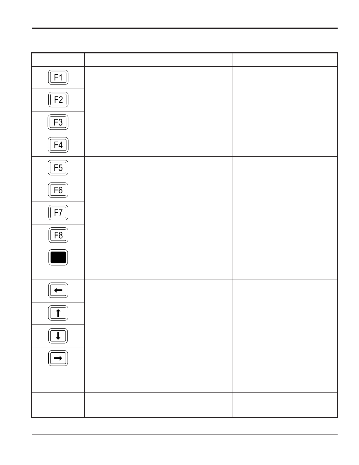
Table 1: Model GF868 Key Functions
Key Unshifted Function Shifted Function
Software Function Keys - press to select the functions
None
displayed directly above them in the option bar. These
keys apply only to the left pane of the display screen.
Software Function Keys - press to select the functions
displayed directly above them in the option bar. These
keys apply only to the right pane of the display screen.
Shift Key - use this red key to access the shifted function of the other keys. One press shifts the next keystroke only, while two presses locks the keypad in
shifted mode. A third press releases the shift function.
Arrow Keys - in measurement mode, use to scroll
through function choices on the option bar. In programming mode, use to scroll through menu choices. The
[ also acts as a backspace key in programming
mode.
None
None
Use to enter the letters A, B, C and D,
respectively.
Program Key - press to enter the User Program. See
Use to enter the letter Q.
page 8 for details.
Display Key - use to display data in a variety of
Use to enter the letter O.
numeric and graphic formatting options. See page 37
for details.
DigitalFlow™ GF868 Programming Manual (1-Channel) 3

Chapter 1. Programming Site Data
Key Unshifted Function Shifted Function
Log Key - use to set up logs. See page 49 for details. Use to enter the letter X.
Table 1: Model GF868 Key Functions (cont.)
Print Key - use to print live measurements, log files and
signal arrays. See page 59 for details.
Clear Key - use to reset totals and to delete site and log
files from the GF868 memory. See page 69 for details.
Calibration Key - use to calibrate the analog inputs and
outputs and to test the alarm relays and the totalizer/frequency outputs. See Chapter 1, Calibration, of the Ser-
vice Manual for details.
Exit Key - use to move up one level in the user program
or to exit the user program. See this chapter for details.
Enter Key - use to confirm the most recent input
information.
Help Key - use to access the Model GF868’s context-sensitive on-line help system. See the next section
for details.
Screen Key - press the left side to select the left display
pane or the right side to select the right display pane.
Use to enter the letter R.
Use to enter the letter H.
Use to enter the letter P.
Use to enter the letter J.
Use to enter the letter K.
Use to enter the letter I.
Press the left side to enter letter V or
press the right side to enter letter W.
Decimal Point Key - press to enter a decimal point dur-
Use to enter the letter Z.
ing numeric entry.
Minus Key - use to enter a minus sign or a dash. Use to enter a space character.
Zero Key - use to enter the number 0. Use to enter the letter Y.
One Key - use to enter the number 1. Use to enter the letter S.
Two Key - use to enter the number 2. Use to enter the letter T.
Three Key - use to enter the number 3. Use to enter the letter U.
Four Key - use to enter the number 4. Use to enter the letter L.
4 DigitalFlow™ GF868 Programming Manual (1-Channel)
Chapter 1. Programming Site Data
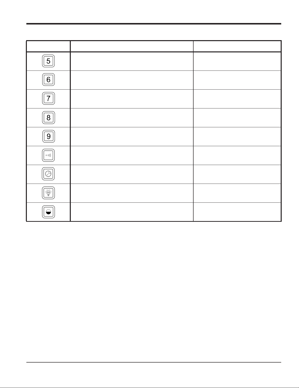
Table 1: Model GF868 Key Functions (cont.)
Key Unshifted Function Shifted Function
Five Key - use to enter the number 5. Use to enter the letter M.
Six Key - use to enter the number 6. Use to enter the letter N.
Seven Key - use to enter the number 7. Use to enter the letter E.
Eight Key - use to enter the number 8. Use to enter the letter F.
Nine Key - use to enter the number 9. Use to enter the letter G.
Audio Level Key - press to increase the audio alarm
volume.
Stopwatch Timer Key - press to turn the stopwatch
timer on.
Backlight Key - press to turn the display backlight on
or to increase its brightness.
Contrast Key - press to increase the contrast of the display screen.
Press to decrease the audio alarm vol-
ume.
Press to turn the stopwatch timer off.
Press to turn the display backlight off
or to decrease its brightness.
Press to decrease the contrast of the
display screen.
DigitalFlow™ GF868 Programming Manual (1-Channel) 5
Chapter 1. Programming Site Data
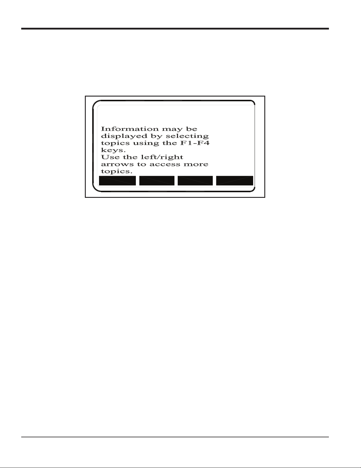
1.3 Obtaining On-line Help
A context-sensitive, on-line help system is programmed into every Model GF868 flowmeter. On-line help, which
displays additional information related to the current task, may be accessed at any time by pressing the [HELP] key on
the keypad. The help information will be shown on the currently selected pane of the display screen, as shown in
Figure 2.
ON-LINE HELP
MORE
Figure 2: Typical On-Line Help Screen
After entering the on-line help system, the following functions are available on the option bar of the selected display
pane:
EXIT
ERROR
FLOW
• MORE: Press [F1] (or [F5]) to access this function, and the next screen of text is displayed in the prompt area.
• EXIT: Press [F2] (or [F6]) to access this function, and the Model GF868 returns to measurement mode.
• ERROR: Press [F3] (or [F7]) to access this function, and the various Model GF868 error codes are displayed. Use the
[F1]-[F4] (or [F5]-[F8]) function keys, in conjunction with the [ and [ keys, to obtain additional information on
the desired error code or to exit the help system.
Note: See the Service Manual for a complete listing of all error codes and messages
• FLOW: Press [F4] (or [F8]) to access this function, and the various flow measurement parameters are displayed. Use
[F1]-[F4] (or [F5]-[F8]) function keys, in conjunction with the [ and [ keys, to obtain additional information
the
on the desired measurement parameter or to exit the help system.
6 DigitalFlow™ GF868 Programming Manual (1-Channel)

Chapter 1. Programming Site Data
1.4 Using the Console Control Keys
The Model GF868 has four console control keys, which are located on the left side of the keypad. Use these keys,
which are described and pictured in Table 1 on page 3, as follows:
1.4.1 Audio Alarm Volume
Use the top console control key to adjust the audio alarm volume.
Discrete presses will incrementally increase the volume of the audio alarm. Hold the key down for continuous increase.
Use the key in shifted mode to decrease the volume of the audio alarm.
1.4.2 Stopwatch Totalizer
Use the second console control key for the stopwatch totalizer.
Press the key once to start the stopwatch totalizer. Press the key once, in shifted mode, to stop the stopwatch totalizer.
Note: Instructions on properly setting up the stopwatch totalizer are given later in this chapter. Also, the Service
Manual provides information on the error response of the stopwatch totalizer.
1.4.3 Display Brightness
Use the third console control key to adjust the display backlight.
Discrete presses of this key will increase the backlight brightness through settings of Off, Mid and Full. Discrete
presses of this key in shifted mode, will decrease the backlight brightness through settings of Full, Mid and Off.
Note: The display backlight has an automatic time-off feature. See page 47 for setup instructions.
1.4.4 Display Contrast
Use the bottom console key to adjust the display contrast.
Discrete presses will incrementally increase the display contrast. Hold the key down for continuous increase. Use the
same key, in shifted mode, to decrease display contrast.
DigitalFlow™ GF868 Programming Manual (1-Channel) 7

Chapter 1. Programming Site Data
1.5 Entering Programming Mode
Use the keypad, as described in the previous section, to navigate through the User Program. The menu map may be
followed in sequence, or the [ and [ keys may be used to scroll through the prompt screens. The [ key may be
used to delete the last alphanumeric character that was entered from the keypad.
The following discussion assumes that the left screen pane is active. If the right screen pane is active, only the function
key designations change. That is, replace [F1]-[F4] with [F5]-[F8].
Note: Be sure to record all the programming data entered in this chapter in Appendix B, Data Records.
Programming of the ACTIV, SYSTM and PIPE submenus is necessary for operation of the Model GF868. Failure to
accurately enter all of the required information will result in unreliable flow rate data. Therefore, be sure to complete at
least the sections of this chapter pertaining to those three submenus.
Note: Because it is so essential, instructions for programming the ACTIV, SYSTM and PIPE submenus are also included
in the Startup Guide. If that programming has already been completed, those sections of this chapter may be
skipped.
Except for the three submenus noted above, it is not necessary to program the Model GF868 flowmeter in any
particular order. Therefore, the sections of this chapter need not be completed in sequence. Proceed immediately to any
section of interest.
To access the User Program, press the [PROG] key on the keypad. The standard measurement mode screen is replaced
by the following initial programming mode screen:
PROGRAM Start
Press the [ and [ keys and one of the function keys [F1]-[F4] to select the
desired submenu. From this screen, press [EXIT] to return to measurement mode.
PROGRAM
status
ACTIV SYSTM PIPE I/O
Note: If the security feature is active, enter the password and press the
SECUR submenu section of this chapter for more information on the security feature.
[ENT] key to enter the User Program. See the
8 DigitalFlow™ GF868 Programming Manual (1-Channel)

Chapter 1. Programming Site Data
1.6 Activating the Channel
The ACTIV submenu permits selection of the desired measurement method. While following the programming
instructions, refer to Figure 11 on page 87.
1. Enter the ACTIV submenu by pressing [F1] at the User PROGRAM prompt.
2. Press [F1] to activate the channel in BURST mode.
Note: The current status of the meter is displayed in the bottom line of the prompt area.
3. Press [F1] to select Skan mode or [F2] to select Skan/Measure mode. The meter will exit the ACTIV submenu and
return to the channel menu screen.
The Model GF868 flowmeter can take measurements in two different ways:
• Skan is a low resolution technique for locating the acoustic signal and for high velocity measurements. It is more
robust in a noisy environment than the Measure technique.
• Measure is a more precise technique best used for low velocity measurements.
If Skan is selected at the next prompt, the instrument uses this technique exclusively. However, if S/M is selected, the
meter uses Skan to find the acoustic signal and then tries to use the Measure technique for a more precise measurement.
Note: To change the Skan and Measure parameters, see the
SIGNL submenu section of this chapter.
1.6.1 Procedure Options
After completing the above steps, the meter returns to the User PROGRAM prompt. Continue as follows:
• To continue programming the meter, refer to the menu maps in Appendix A and navigate to the desired menu.
Then, proceed to the appropriate section of the manual for instructions.
• To leave the User Program and retain the previous settings, press [EXIT] and then press [F1] = NO at the SAVE
prompt. Any programming changes will be discarded and you will be returned to the data display.
• To leave the User Program and return to measurement mode, press [EXIT] and then press [F2] = YES at the SAVE
prompt. Your programming changes will be entered into the meter’s memory , and you will be returned to the data
display.
DigitalFlow™ GF868 Programming Manual (1-Channel) 9

Chapter 1. Programming Site Data
1.7 Entering System Data
1. At the User Program screen, press the [F2] function key to program the SYSTM submenu.
2. Enter a Site Label of up to 9 characters and press [ENT]. (While taking measurements, the site label will appear on
the locator bar.)
3. Enter a Site Message of up to 21 characters. Press [ENT].
1.7.1 Entering System Units
4. To select the System Units, press [F1] to display parameters and measurements in English units, or press [F2] to
display parameters and measurements in Metric units.
5. Use the [F1]-[F4] keys to select the type of Pressure Units desired. The available pressure units are shown in
Figure 11 on page 87. The choices shown on the option bar are determined by the selections made at the previous
SYSTEM UNITS prompt.
a. If you have entered gage pressure, or the local atmospheric pressure (PSIg, BARg or kPag), use the numeric
keys to enter the gage pressure value. Press [ENT].
6. At the Stopwatch Totalizer prompt, press [F1] to totalize all liquid flow continuously, or [F2] to measure totals
manually with the Stopwatch Timer. (With MNUAL ([F2]), the console key on the keypad is used to start and stop the
totalizer. See page 7 for details.)
IMPORTANT: After setting up the Stopwatch Totalizer , press [CLR] to clear the Stopwatch Totalizer, or the new totals will
be added to any previously accumulated totals.
Note: The manner in which the Stopwatch Totalizer responds to an error condition may be set in the I/O submenu.
1.7.2 Entering Volumetric Data
7. Use the [F1]-[F4] and [ keys to select the desired Volumetric Units for the flow rate display. The available
volumetric and totalizer units are shown in Figure 11 on page 87.
8. Use the [F1]-[F4] keys to select the Volumetric Time (units for the volumetric flow rate display).
9. Use the [F1]-[F4] keys to select the Vol Decimal Digits (the desired number of digits to the right of the decimal
point) in the volumetric flow rate display.
10 DigitalFlow™ GF868 Programming Manual (1-Channel)

Chapter 1. Programming Site Data
1.7.3 Entering Totalizer Data
10. Use the [F1]-[F4] and [ keys to select the Totalizer Units.
11. Use the [F1]-[F4] keys to select the Total Decimal Digits (the desired number of digits to the right of the decimal
point) in the totalized flow display.
1.7.4 Entering Mass Flow Data.
12. Use the [F1]-[F4] keys to select the Mass Flow units, listed in Figure 11 on page 87.
13. Use the [F1]-[F4] keys to select the Mass Flow Time units.
14. Use the [F1]-[F4] keys to select the MDOT Decimal Digits (the number of digits to the right of the decimal point) for
displaying mass flow.
15. Use the [F1]-[F4] keys to select the Mass (Totalizer) units.
16. Use the [F1]-[F4] to specify the Mass Decimal Digits (the number of digits to the right of the decimal point) for
displaying totalized mass flow. The meter returns to the initial User Program screen.
1.7.4a Procedure Options
After completing the above steps, the meter returns to the User PROGRAM prompt. Continue as follows:
• To continue programming the meter, refer to the menu maps in Appendix A and navigate to the desired menu.
Then, proceed to the appropriate section of the manual for instructions.
• To leave the User Program and retain the previous settings, press [EXIT] and then press [F1] = NO at the SAVE
prompt. Any programming changes will be discarded and you will be returned to the data display.
• To leave the User Program and return to measurement mode, press [EXIT] and then press [F2] = YES at the SAVE
prompt. Your programming changes will be entered into the meter’s memory , and you will be returned to the data
display.
DigitalFlow™ GF868 Programming Manual (1-Channel) 11

Chapter 1. Programming Site Data
1.8 Entering Pipe Data
Enter the transducer and pipe parameters using the PIPE submenu. While following the programming instructions, refer
to Figure 11 on page 87. To program this menu, complete the following steps:
1. At the User (or Channel) Program screen, press [F3] to program the PIPE submenu.
2. Enter the Transducer Number (normally engraved on the head of the transducer). Press [ENT]. If there is no
engraved number, complete the steps below. Otherwise, proceed to step 3.
IMPORTANT: Special transducers, which have no engraved number on the head, are rarely used. Examine the
transducer head carefully for a number.
1.8.1 Special Transducers
a. Assign a number between 91 and 99 to the Special Transducer and press [ENT]. (The meter will only accept
values from 1 to 199.)
b. Use the [ and [F1]-[F4] keys to select the Frequency of the special transducer. The meter can not transmit an
excitation voltage at the transducer’s natural frequency without this data.
c. Enter the special transducer Time Delay (Tw) value supplied by the factory. Press [ENT]. (The meter will only
accept values from 0 to 1000 sec.)
Note: T w is the time required for the transducer signal to travel through the transducer and its cable. This time delay
must be subtracted from the transit times of the upstream and downstream transducers to ensure an accurate
measurement.
1.8.2 Pipe OD
3. Enter the known Pipe OD or circumference and use the [F1]-[F4] keys to select the appropriate units. Press [ENT].
(The meter will only accept values from 1/8 to 648 in.) The option bar choices, listed in Figure 11 on page 87, may
appear in English or Metric units. Obtain the required information by measuring either the pipe outside diameter
(OD) or circumference at the transducer installation site. The data may also be obtained from standard pipe size
tables.
1.8.3 Pipe Wall
4. Use the numeric keys to enter the known thickness of the Pipe Wall. Press [ENT].
IMPORTANT: Because the units cannot be independently chosen for this parameter, the value must be entered in the
same units used for the pipe OD.
If the pipe wall thickness is not available, look up the value in a table of standard pipe size data or use the Model
GF868’s on-line Help Menu (see the Programming Manual for details).
12 DigitalFlow™ GF868 Programming Manual (1-Channel)

Chapter 1. Programming Site Data
1.8.4 Path Length
5. Press [F1] = inch or [F2] = feet to select the units. Then, enter the Path Length (P) of the ultrasonic signal. Press
[ENT]. (The meter will only accept values from 1/8 to 900 in.)
Note: The factory has calculated both the transducer signal path length (P) and the transducer signal axial length (L),
based on the exact transducer configuration used for the application. These values are engraved on the
flowcell and/or are included in the documentation supplied with the meter.
1.8.5 Axial Length
6. Press [F1] = inch or [F2] = feet to select the units.Then, enter the Axial Length (L) of the ultrasonic signal and press
[ENT].
Note: The factory has calculated both the transducer signal path length (P) and the transducer signal axial length (L),
based on the exact transducer configuration used for the application. These values are engraved on the
flowcell and/or are included in the documentation supplied with the meter.
1.8.6 Reynolds Correction
7. Press [F1] to turn Reynolds Correction off, or [F2] to turn it on.
Note: Reynolds Correction is a number based on the Kinematic Viscosity and flow rate of the fluid. It should be
enabled for most applications.
a. When you enable the Reynolds Correction Factor, you must also enter the Kinematic Viscosity of your gas, as
listed in Sound Speeds and Pipe Size Data. Use the numeric keys to enter a value, and press [ENT].
1.8.7 Calibration Factor
8. Enter a value for the flow Calibration Factor and press [ENT]. The default value is 1.00. (The meter will only accept
values between 0.50 and 2.00.)
1.8.7a Procedure Options
After completing the above steps, the meter returns to the User PROGRAM prompt. Continue as follows:
• To continue programming the meter, refer to the menu maps in Appendix A and navigate to the desired menu.
Then, proceed to the appropriate section of the manual for instructions.
• To leave the User Program and retain the previous settings, press [EXIT] and then press [F1] = NO at the SAVE
prompt. Any programming changes will be discarded and you will be returned to the data display.
• To leave the User Program and return to measurement mode, press [EXIT] and then press [F2] = YES at the SAVE
prompt. Your programming changes will be entered into the meter’s memory , and you will be returned to the data
display.
DigitalFlow™ GF868 Programming Manual (1-Channel) 13

Chapter 1. Programming Site Data
1.9 Setting Up Inputs/Outputs
Set up the GF868’s inputs and outputs using the four options in the I/O submenu. While following the programming
instructions, refer to Figure 12 on page 88.
• ERROR - program the meter’s response during an error condition
• OPTN - set up the Slot 0 analog outputs and any option cards
• ZERO - set the meter’s zero point cutoff value
• T,P - set up the temperature and pressure inputs
Enter the
option.
Note: In this section, a slot’s number will appear on the option bar only if an option card is installed in that slot. The
Proceed to the appropriate section to program the option selection made at the above prompt. Remember to record all
programmed data in Appendix B, Data Records.
I/O submenu by pressing [F4] at the initial User Program screen. Then press [F1]-[F4] to select the desired I/O
generic designations Slot x and Fx are used to indicate any one of the expansion slots and the function key used
to select it.
1.9.1 Selecting Error Handling
This menu option permits programming of the manner in which the Model GF868’s totalizers respond during an error
condition. See Chapter 2, Error Codes and Screen Messages, of the Service Manual for a discussion of the built-in
error codes.
1. At the I/O prompt, press [F1] = Error.
2. Press [F1] if you want the GF868 to Hold the last “good” reading and continues to totalize, based on that reading, or
press [F2], No Up, if you want the meter to stop totalizing.
14 DigitalFlow™ GF868 Programming Manual (1-Channel)

Chapter 1. Programming Site Data
1.9.2 Setting Up Analog Outputs
The Model GF868 has two built-in analog outputs, which are assigned to Slot 0. Also, a variety of option cards may be
installed in the six expansion slots. See Chapter 1, Installation, of the Startup Guide for a complete description of the
available option cards.
This menu option is used to set up and/or scale the analog inputs and outputs. To accomplish this, complete the
following steps:
1. Use the and [ and the [F1]-[F4] keys to select the desired slot number. (Only those slots which contain an
option card will appear on the option bar.)
Note: If the number of a slot with an installed option card does not appear, the card may not have been initialized or
it may be defective. Call the factory for assistance.
Complete the following steps to set up the Slot x analog outputs:
1. Use the [F1]-[F4] keys to set up outputs A, B, C or D, respectively.
Note: The set up of output A is used as an example. Identical procedures would be used to set up the other outputs.
2. Press [F1] = OFF to disable output A and return to the previous prompt, or press [F2] = 0-20 m or [F3] = 4-20 m to
specify the desired range for output A.
3. Use the and [ and [F1]-[F4] keys to specify the desired Output Measurement parameter (see Figure 11 on
page 87).
4. Enter the Zero value for the low end of the chosen output range. Press [ENT].
5. Enter the Full value for the high end of the chosen output range. Press [ENT].
6. Use the [F1]-[F4] keys to set up another output or press [EXIT] to select another slot for setup.
For instructions on setting up additional inputs and/or outputs proceed to the appropriate section. Otherwise, press
[EXIT] to return to the main I/O menu prompt.
DigitalFlow™ GF868 Programming Manual (1-Channel) 15

Chapter 1. Programming Site Data
1.9.3 Option Card Alarms
1. Use the and [ and the [F1]-[F4] keys to select the desired slot number.
2. Use the [F1]-[F3] keys to set up alarm relays A, B, or C, respectively.
Note: The set up of alarm A is used as an example. Identical procedures would be used to set up the other alarms.
3. Press [F1] = OFF to disable Alarm A and return to the previous prompt, or press [F2] = HIGH, [F3] = LOW or [F4] =
FAULT to specify the type for Alarm A.
4. Press [F1] = NO for standard operation or [F2] = YES for Failsafe operation.
5. Do one of the following:
• If you selected FAULT, proceed to step 6.
• If you selected HIGH or LOW, complete the steps below.
a. Use the and [ and
Figure 12 on page 88.
b. Enter a value for the trigger point of the alarm and press [ENT].
6. To select the Fault Type that will trigger the alarm, press F1 = FLOW, F2 = OTHER (non-flow), or F3 = ALL.
7. Press [F1]-[F3] to set up another alarm or press [EXIT] to select another slot for set up.
For instructions on setting up additional inputs and/or outputs proceed to the appropriate section. Otherwise, press
[EXIT] to return to the main I/O menu prompt.
[F1]-[F4] keys to specify the desired Output Measurement parameter, as shown in
16 DigitalFlow™ GF868 Programming Manual (1-Channel)

Chapter 1. Programming Site Data
1.9.4 Setting Up the Totalizer/Frequency Outputs
1. Press [F1]-[F4] to set up outputs A, B, C or D, respectively.
2. Press [F1] = OFF to disable output A and return to the previous prompt, or press [F2] = FREQ or [F3] = TTLZR to
designate output A as a frequency or a totalizer output, respectively.
Note: The setup of output A is used as an example. Identical procedures would be used to set up the other outputs.
• To program a frequency output, go to step 3.
• To program a totalizer output, go to step 4.
1.9.4a Programming a Frequency Output
3. The FREQ output, [F2], produces a frequency pulse that is proportional to the output measurement. Complete the
steps below to program the frequency output.
a. Use the and [ and [F1]-[F4] keys to specify the desired Output Measurement parameter.
b. Enter the Base value for the low end of the frequency output range and press [ENT].
c. Enter the Full value for the high end of the frequency output range. Press [ENT].
d. Enter a value between 1 and 10,000 for the Full Scale Frequency. Press [ENT].
Programming a Totalizer Output
4. The TTLZR output, [F3], issues one pulse per selected volume of flow. The meter produces a pulse each time the
programmed amount of flow passes through the pipe. Complete the steps below to program the totalizer output.
a. Press [F1] = +TOTL to totalize the forward flow, [F2] = -TOTL to totalize the reverse flow, [F3] = +MASS (if
available) to totalize the forward mass flow or [F4] = -MASS (if available) to totalize reverse mass flow.
b. Enter a value from 50 to 500,000 sec for the Minimum Pulse ON Time and press [ENT].
Note: A complete pulse consists of equal amounts of ON and OFF times. Choose a value that is compatible with the
frequency counter to be used.
c. Enter a value for the number of measurement Units/Pulse and press [ENT].
5. Press [F1]-[F4] to set up another totalizer/frequency output or press [EXIT] to select another slot for setup.
DigitalFlow™ GF868 Programming Manual (1-Channel) 17

Chapter 1. Programming Site Data
1.9.5 Setting up the Analog Inputs
1. Press [F1] to set up input A or [F2] to set up input B.
Note: The set up of input A is used as an example in this manual. Identical procedures would be used to set up input
B. (An analog input option card may contain one standard analog input and one RTD analog input.)
2. Enter a Label of up to eight characters for input A and press [ENT].
3. At the Input Measurement prompt, press [F1] = OFF to disable input A and return to the previous prompt, or press
[F2] = PRESR (pressure), [F3]= TEMP (temperature) or [F4] = SPEC (special) to designate the input.
4. Do one of the following:
• If you selected PRESR or TEMP, proceed to step 5.
• If you selected SPEC, complete the steps below.
a. Enter an Input Name and press
b. Enter the Input Units of measurement and press [ENT].
5. Enter the Zero Value for the low end of the chosen input range and press [ENT].
6. Enter the Full Scale Value for the high end of the chosen input range and press [ENT].
7. Press [F1]-[F2] to set up another input or press [EXIT] to select another slot for setup.
For instructions on setting up additional inputs and/or outputs proceed to the appropriate section. Otherwise, press
[EXIT] to return to the main I/O menu prompt.
[ENT].
18 DigitalFlow™ GF868 Programming Manual (1-Channel)

Chapter 1. Programming Site Data
1.9.6 Setting up RTD Inputs
Option cards with R TD inputs have a temperature range of –100° to 350°C. Complete the following steps to set up the
two RTD inputs of an option card installed in Slot x:
1. Press [F1] to set up RTD input A or [F2] to set up RTD input B.
Note: The setup of RTD input A is used as an example. Identical procedures would be used to set up RTD input B.
2. Enter a label of up to eight characters and press [ENT].
3. At the Input Measurement prompt, press [F1] = OFF to disable RTD input A and return to the previous prompt, or
press [F2] = TEMP to enable RTD input A.
4. Enter the Zero Value for the low end of the chosen input range and press [ENT].
5. Enter the Full Scale Value for the high end of the chosen input range and press [ENT].
6. Press [F1]-[F2] to set up another input or press [EXIT] to select another slot for set up.
For instructions on setting up additional inputs and/or outputs proceed to the appropriate section. Otherwise, press
[EXIT] to return to the main I/O menu prompt.
1.9.7 Entering the Zero Cutoff
Near zero flow, the Model GF868’s readings may fluctuate due to small offsets caused by thermal drift or similar
factors. To force a zero reading when there is minimal flow, enter a zero cutoff value as described below:
1. At the main I/O menu prompt, press [F3] = ZERO.
2. Enter the desired Zero Cutoff value and press the [ENT] key. A value of 0.1 ft/s (0.03 m/s) is recommended, but
values from 0–1 ft/s (0–0.3 m/s) are acceptable. The menu returns to the main I/O prompt.
DigitalFlow™ GF868 Programming Manual (1-Channel) 19

Chapter 1. Programming Site Data
1.9.8 Setting Up Temperature and Pressure Inputs
The Model GF868 can use either fixed temperature and pressure quality values or live measurement inputs to calculate
standard volumetric or mass flow. Complete the following steps to configure these inputs:
1. At the main I/O menu prompt, press [F4] =T,P.
1.9.8a Entering the Temperature Input
2. At the Temperature Input prompt, press [F1] to enter a constant temperature value or press [Fx] to select the option
card in Slot x that will supply the live temperature input.
Note: Each slot that contains an option card with an analog input assigned to TEMP or an RTD input will appear on
the option bar. If the process temperature is stable, a fixed value may be used, but most applications require a
live temperature input.
3. Do one of the following:
• If you selected FIXED, enter the known fixed process temperature. Press [ENT]. (The meter will only accept values
from –148° to 662°F.)
• If you selected SLOT X,
a. Press
Note: The set up of input A is used as an example. Identical procedures would be used to set up input B.
b. Enter the Base Temperature (from –148° to 662°F), and press [ENT]. The ratio of this value to the actual
[F1] to select input A or press [F2] to select input B.The inputs were labeled during setup.
temperature is used to calculate the standard volumetric flow.
1.9.8b Entering the Pressure Input
4. At the Pressure Input prompt, press [F1] to enter a constant pressure value or press [Fx] to select the option card in
Slot X that will supply the live pressure input.
Note: Each slot that contains an option card with an analog input assigned to PRESR will appear on the option bar. If
the process pressure is stable, a fixed value may be used, but most applications require a live pressure input.
5. Do one of the following:
• If you selected FIXED, enter the known fixed process pressure. Press [ENT]. (The meter will only accept values
from 0–5000 psia.)
20 DigitalFlow™ GF868 Programming Manual (1-Channel)
Loading...