


 Loading...
GE Fanuc Automation
Programmable Control Products
Field Control™
Genius® Bus Interface Unit
User’s Manual
GFK-0825F |
October 1999 |

GFL-002
Warnings, Cautions, and Notes as Used in this Publication
Warning
Warning notices are used in this publication to emphasize that hazardous voltages, currents, temperatures, or other conditions that could cause personal injury exist in this equipment or may be associated with its use.
In situations where inattention could cause either personal injury or damage to equipment, a Warning notice is used.
Caution
Caution notices are used where equipment might be damaged if care is not taken.
Note
Notes merely call attention to information that is especially significant to understanding and operating the equipment.
This document is based on information available at the time of its publication. While efforts have been made to be accurate, the information contained herein does not purport to cover all details or variations in hardware or software, nor to provide for every possible contingency in connection with installation, operation, or maintenance. Features may be described herein which are not present in all hardware and software systems. GE Fanuc Automation assumes no obligation of notice to holders of this document with respect to changes subsequently made.
GE Fanuc Automation makes no representation or warranty, expressed, implied, or statutory with respect to, and assumes no responsibility for the accuracy, completeness, sufficiency, or usefulness of the information contained herein. No warranties of merchantability or fitness for purpose shall apply.
The following are trademarks of GE Fanuc Automation North America, Inc.
Alarm Master |
Genius |
ProLoop |
Series Three |
CIMPLICITY |
Helpmate |
PROMACRO |
VersaMax |
CIMPLICITY 90–ADS |
Logicmaster |
Series Five |
VersaPro |
CIMSTAR |
Modelmaster |
Series 90 |
VuMaster |
Field Control |
Motion Mate |
Series One |
Workmaster |
GEnet |
PowerTRAC |
Series Six |
|
©Copyright 1996-1999 GE Fanuc Automation North America, Inc.
All Rights Reserved.

Preface
Content of this Manual
This manual describes the Field Control® Genius™ Bus Interface Unit (IC670GBI002). It explains operation of the Bus Interface Unit as a Genius bus device. It also contains complete configuration instructions for the Bus Interface Unit and all Field Control I/O modules.
Chapter 1. Introduction: Chapter 1 introduces Field Control systems, the Genius Bus Interface Unit, and other equipment that may be used with the Bus Interface Unit. It will help you locate more information about the components and operation of Field Control products.
Chapter 2. Description: Chapter 2 describes the Genius Bus Interface Unit module, the Bus Interface Unit Power Supply, and the Bus Interface Unit Terminal Block, and lists their specifications.
Chapter 3. Installation: Chapter 3 describes Bus Interface Unit installation and gives system installation guidelines.
Chapter 4. Operation: Chapter 4 explains how a Bus Interface Unit interacts with the modules in its station, how it stores data, and how it exchanges data with a PLC or other type of system host.
Chapter 5. Station Configuration: Chapter 5 explains how to configure a Bus Interface Unit and the modules in a station using a Hand-held Monitor.
Chapter 6. Diagnostics and Fault Clearing: Chapter 6 describes the diagnostics capabilities of the Bus Interface Unit and explains how faults are cleared.
Chapter 7. Monitoring and Controlling Field Control Data: Chapter 7 explains how to monitor or control Field Control I/O data using Genius Hand-held Monitor or a programmer.
Chapter 8. Datagrams: Chapter 8 lists datagrams that can be sent to a Bus Interface Unit, and shows the datagram formats for Field Control modules.
Appendix A. Scaling Analog Channels: Appendix A explains how to select scaling values when configuring an analog input or output. (Configuration instructions are in chapter 5).
Appendix B. Installing Additional Suppression: Appendix B describes some precautions that can be taken in an installation to help assure proper operation.
Appendix C. The Genius Serial Bus: This appendix describes the selection and operating characteristics of the bus cable that links Genius devices.
Appendix D. Configuration Examples: This appendix includes examples of different Field Control I/O Station configurations.
GFK-0825F |
iii |

Preface
Related Publications
For more information, refer to these publications:
Field Control I/O Modules User's Manual (GFK-0826). This book describes Field Control I/O Modules and I/O Terminal Blocks and explains how to install them.
The Series 90® Micro Field Processor User's Manual (GFK-1171). This book describes the Micro Field Processor (IC670MFP100) and provides installation procedures, operation information, and diagnostics information.
Genius I/O System User's Manual (GEK-90486-1). Reference manual for system designers, programmers, and others involved in integrating Genius I/O products in a PLC or host computer environment. This book provides a system overview, and describes the types of systems that can be created using Genius products. Datagrams, Global Data, and data formats are defined.
Series 90® −30 Bus Controller User's Manual (GFK-1034). Reference manual for the Bus Controller, which interfaces a Genius bus to a Series 90-30 PLC. This book describes the installation and operation of the Bus Controller.
Series Six® Bus Controller User's Manual (GFK-0171). Reference manual for the Bus Controller, which interfaces a Genius bus to a Series Six PLC. This book describes the installation and operation of the Bus Controller. It also contains the programming information needed to interface Genius I/O devices to a Series Six PLC.
Series Five® Bus Controller User's Manual (GFK-0248). Reference manual for the Bus Controller, which interfaces a Genius bus to a Series Five PLC. This book describes the installation and operation of the Bus Controller. It also contains the programming information needed to interface Genius I/O devices to a Series Five PLC.
Genius I/O PCIM User's Manual (GFK-0074). Reference manual for the PCIM, which interfaces a Genius bus to a suitable host computer. This book describes the installation and operation of the PCIM. It also contains the programming information needed to interface Genius I/O devices to a host computer.
Installation Requirements for Conformance to Standards (GFK-1179)
Jeanne Grimsby
Lead Technical Writer for I/O Products
iv |
Field Control™ Genius® Bus Interface Unit User’s Manual– October 1999 |
GFK-0825F |

Contents
Chapter 1 |
Introduction..................................................................................................... |
1-1 |
|
Overview...................................................................................................................... |
1-1 |
|
Field Control Modules .................................................................................................. |
1-2 |
|
Environmental Specifications........................................................................................ |
1-5 |
|
Configuration for Field Control..................................................................................... |
1-6 |
|
Field Control in a Genius System.................................................................................. |
1-7 |
|
Required Genius and Host System Equipment............................................................... |
1-9 |
|
Using Field Control in a CPU Redundancy System ..................................................... |
1-10 |
|
Using Field Control in a Genius Bus Redundancy System........................................... |
1-11 |
Chapter 2 |
Description....................................................................................................... |
2-1 |
|
Genius Bus Interface Unit ............................................................................................. |
2-1 |
|
Bus Interface Unit Power Supply .................................................................................. |
2-3 |
|
Backplane Current ........................................................................................................ |
2-4 |
|
Bus Interface Unit Power Dissipation............................................................................ |
2-5 |
|
Load Requirements for Hardware Components ............................................................. |
2-6 |
|
Bus Interface Unit Terminal Block................................................................................ |
2-8 |
|
Functional Specifications .............................................................................................. |
2-9 |
Chapter 3 |
Installation....................................................................................................... |
3-1 |
|
Preinstallation Check .................................................................................................... |
3-2 |
|
Static Protection............................................................................................................ |
3-2 |
|
Hand-held Monitor Connector ...................................................................................... |
3-2 |
|
System Wiring Guidelines ............................................................................................ |
3-3 |
|
Installing Additional Suppression.................................................................................. |
3-3 |
|
System Grounding ........................................................................................................ |
3-4 |
|
Locations for Field Control ........................................................................................... |
3-5 |
|
Installing the DIN Rail.................................................................................................. |
3-5 |
|
Installing the Bus Interface Unit Terminal Block on the DIN Rail ................................. |
3-7 |
|
Installing the Cables Between Terminal Blocks............................................................. |
3-8 |
|
Power Wiring to the Bus Interface Unit......................................................................... |
3-9 |
|
Connecting the Communications Bus.......................................................................... |
3-10 |
|
Bus Cables.................................................................................................................. |
3-10 |
|
Making Bus Connections ............................................................................................ |
3-11 |
|
Installing the Bus Interface Unit on the Terminal Block .............................................. |
3-14 |
|
Removing the Bus Interface Unit from the Terminal Block ......................................... |
3-14 |
|
Removing/Replacing the Bus Interface Unit Fuse ....................................................... |
3-15 |
|
Upgrading the BIU Firmware...................................................................................... |
3-16 |
GFK-0825F |
v |

Contents
Chapter 4 |
Operation......................................................................................................... |
4-1 |
|
BIU Data Handling at the I/O Station............................................................................ |
4-2 |
|
I/O Data for Conventional Modules .............................................................................. |
4-3 |
|
I/O Data, Status Data, and Control Data for Intelligent Modules.................................... |
4-3 |
|
Group Data for Intelligent Modules............................................................................... |
4-4 |
|
The BIU Sweep ............................................................................................................ |
4-5 |
|
BIU Backplane Scan Time............................................................................................ |
4-7 |
|
Data Transfer Between the BIU and the Host ................................................................ |
4-9 |
|
Data in the BIU's Network (Bus) Map........................................................................... |
4-9 |
|
Communications on the Genius Bus.............................................................................. |
4-9 |
|
Input Data Sent by the Bus Interface Unit ................................................................... |
4-10 |
|
Outputs from the Host to the BIU................................................................................ |
4-11 |
|
Genius Bus Scan Time................................................................................................ |
4-12 |
|
Operation of the BIU with a Micro Field Processor ..................................................... |
4-14 |
|
MFP and BIU Synchronization ................................................................................... |
4-14 |
|
MFP I/O References ................................................................................................... |
4-14 |
|
MFP Operating Modes................................................................................................ |
4-14 |
|
Overview of Synchronous Operation........................................................................... |
4-16 |
|
Backing Up Micro Field Processor Outputs ................................................................ |
4-17 |
|
How the Network Backs Up MFP Outputs.................................................................. |
4-18 |
|
Backing Up BIU Outputs with a Micro Field Processor............................................... |
4-19 |
|
Example Ladder Logic................................................................................................ |
4-20 |
Chapter 5 |
Station Configuration...................................................................................... |
5-1 |
|
For Additional Information, Also See: .......................................................................... |
5-1 |
|
Configuring the Serial Bus Address and Baud Rate....................................................... |
5-2 |
|
Special Instructions for Series 90-70 PLC Systems ....................................................... |
5-2 |
|
Set Up the Hand-held Monitor ...................................................................................... |
5-3 |
|
Create a New Configuration.......................................................................................... |
5-4 |
|
Assigning a Serial Bus Address to a New BIU .............................................................. |
5-4 |
|
Configure the Bus Interface Unit................................................................................... |
5-5 |
|
Field Control HHM Menu Overview............................................................................. |
5-6 |
|
Change the Serial Bus Address of the Bus Interface Unit .............................................. |
5-7 |
|
Select the Baud Rate..................................................................................................... |
5-8 |
|
Select a Series Six or Series Five PLC Reference Address............................................. |
5-9 |
|
Configure Fault Reporting .......................................................................................... |
5-10 |
|
Configure Genius Bus Redundancy............................................................................. |
5-11 |
|
Configure CPU Redundancy ....................................................................................... |
5-12 |
|
Configure Field Control Modules................................................................................ |
5-15 |
|
Enable/Disable the I/O Scan ....................................................................................... |
5-15 |
vi |
Field Control™ Genius® Bus Interface Unit User’s Manual– October 1999 |
GFK-0825F |

Contents
|
Disable Network I/O Updates ..................................................................................... |
5-15 |
|
Configure the Network Map for the Bus Interface Unit ............................................... |
5-16 |
|
Configuring Extra References in the BIU I/O Map...................................................... |
5-17 |
|
Add Modules and Assign References .......................................................................... |
5-20 |
|
Configure a Discrete Input Module ............................................................................. |
5-22 |
|
Configure a Discrete Output Module........................................................................... |
5-24 |
|
Configure a Discrete Input/Output Module.................................................................. |
5-26 |
|
Configure a Conventional Analog Input Module ......................................................... |
5-29 |
|
Configure a Conventional Analog Output Module....................................................... |
5-35 |
|
Configure a 16-Point Grouped Analog Input Module .................................................. |
5-40 |
|
Configure an 8-Point Grouped Analog Voltage Input Module ..................................... |
5-48 |
|
Configure a 16-Point Grouped Analog Voltage Input Module ..................................... |
5-56 |
|
Circuit Configuration.................................................................................................. |
5-60 |
|
Configure an RTD Input Module ................................................................................ |
5-64 |
|
Circuit Configuration.................................................................................................. |
5-67 |
|
Configuring a Thermocouple Input Module................................................................. |
5-72 |
|
Configure an 8-Point Analog Voltage Output Module ................................................. |
5-81 |
|
Configure an 8-Point Analog Current Output Module ................................................. |
5-90 |
|
Configure a Micro Field Processor.............................................................................. |
5-99 |
Chapter 6 |
Diagnostics and Fault Clearing....................................................................... |
6-1 |
|
Diagnostics and Fault Clearing for Intelligent Modules ................................................. |
6-1 |
|
Diagnostics and Fault Clearing for the BIU and Conventional Modules......................... |
6-2 |
|
Display and Clear Faults from a Genius Hand-held Monitor.......................................... |
6-3 |
|
Display and Clear Faults from a PLC ............................................................................ |
6-5 |
|
Series 90 PLC: I/O Fault Table .................................................................................... |
6-5 |
|
Series 90 PLC: PLC Fault Table ................................................................................... |
6-5 |
|
Series Five or Series Six PLC ....................................................................................... |
6-5 |
GFK-0825F |
Contents |
vii |

Contents
Chapter 7 |
Monitoring and Controlling Field Control Data............................................ |
7-1 |
|
Overview...................................................................................................................... |
7-2 |
|
Forcing Circuits ............................................................................................................ |
7-2 |
|
Overriding I/O Circuits ................................................................................................. |
7-2 |
|
Monitor/Control I/O Data: Genius Hand-held Monitor .................................................. |
7-3 |
|
Forcing/Unforcing the Displayed Reference.................................................................. |
7-5 |
|
Monitor/Control I/O Data: Series 90 PLC .................................................................... |
7-6 |
|
Monitor/Control I/O Data: Series Six PLC or Series Five PLC ..................................... |
7-6 |
|
Monitor/Control I/O Data: Computer ............................................................................ |
7-7 |
Chapter 8 |
Datagrams ....................................................................................................... |
8-1 |
|
Datagram Types............................................................................................................ |
8-2 |
|
Read Map ..................................................................................................................... |
8-3 |
|
Read Map Reply........................................................................................................... |
8-3 |
|
Write Map .................................................................................................................... |
8-4 |
|
Report Fault Datagram Format...................................................................................... |
8-5 |
|
Configuration Data ....................................................................................................... |
8-7 |
|
Read Configuration Data .............................................................................................. |
8-7 |
|
Set Bus Interface Unit Operating Mode....................................................................... |
8-29 |
|
Set Micro Field Processor Operating Mode ................................................................. |
8-29 |
|
Intelligent Analog Module Recalibration Datagram..................................................... |
8-30 |
|
Read I/O Forces .......................................................................................................... |
8-32 |
|
Read I/O Forces Reply................................................................................................ |
8-32 |
|
Read Slot Diagnostics ................................................................................................. |
8-33 |
|
Read Slot Diagnostics Reply....................................................................................... |
8-33 |
viii |
Field Control™ Genius® Bus Interface Unit User’s Manual– October 1999 |
GFK-0825F |

Contents
Appendix A Scaling Analog Channels................................................................................. |
A-1 |
How Scaling Works ..................................................................................................... |
A-1 |
Scaling Values for 1mV or 1µ A Engineering Units: BIU Version 1.3 ........................... |
A-2 |
Scaling Values for 1mV or 1µ A Engineering Units: BIU.............................................. |
A-3 |
Measuring Scaling Values............................................................................................ |
A-4 |
Example of Scaling an Analog Input ............................................................................ |
A-5 |
Appendix B |
Installing Additional Suppression .................................................................. |
B-1 |
|
Suppression at the Power Lines.................................................................................... |
B-1 |
|
Suppression for Devices in an Enclosure...................................................................... |
B-2 |
|
Suppression at the Communications Line..................................................................... |
B-2 |
Appendix C The Genius Serial Bus..................................................................................... |
C-1 |
Wiring Guidelines........................................................................................................ |
C-1 |
Electrical Interface....................................................................................................... |
C-2 |
Genius Transceiver Electrical Specification ................................................................. |
C-3 |
Selecting a Cable Type ................................................................................................ |
C-4 |
Serial Bus Waveforms ................................................................................................. |
C-5 |
Using Other Cable Types ............................................................................................. |
C-6 |
Serial Data Format....................................................................................................... |
C-8 |
Bus Access .................................................................................................................. |
C-9 |
Bus Length ................................................................................................................ |
C-10 |
Baud Rate Selection................................................................................................... |
C-10 |
Bus Ambient Electrical Information........................................................................... |
C-11 |
Lightning Transient Suppression................................................................................ |
C-11 |
Appendix D Configuration Examples ................................................................................. |
D-1 |
Example 1: Discrete Data, Network Processing............................................................ |
D-1 |
Example 2: Discrete and Analog Data, Network Processing ......................................... |
D-2 |
Example 3: Discrete and Analog Data, Network and Local Processing ......................... |
D-3 |
Example 4: Discrete and Analog Data, Network and Local Processing and Group Data |
|
Moves ...................................................................................................................... |
D-4 |
Example 5: Group Move............................................................................................. |
D-6 |
GFK-0825F |
Contents |
ix |
Chapter Introduction
1
|
This chapter introduces Field Control™ modules, the Genius™ Bus Interface Unit, and other |
|
|
equipment that may be used with the Bus Interface Unit. It will help you locate more information |
|
|
in other Field Control and Genius documents. |
|
Overview |
|
|
|
Field Control is a family of highly modular distributed I/O and control products. They are suitable |
|
Bus |
for use in a wide range of host architectures. |
|
Interface |
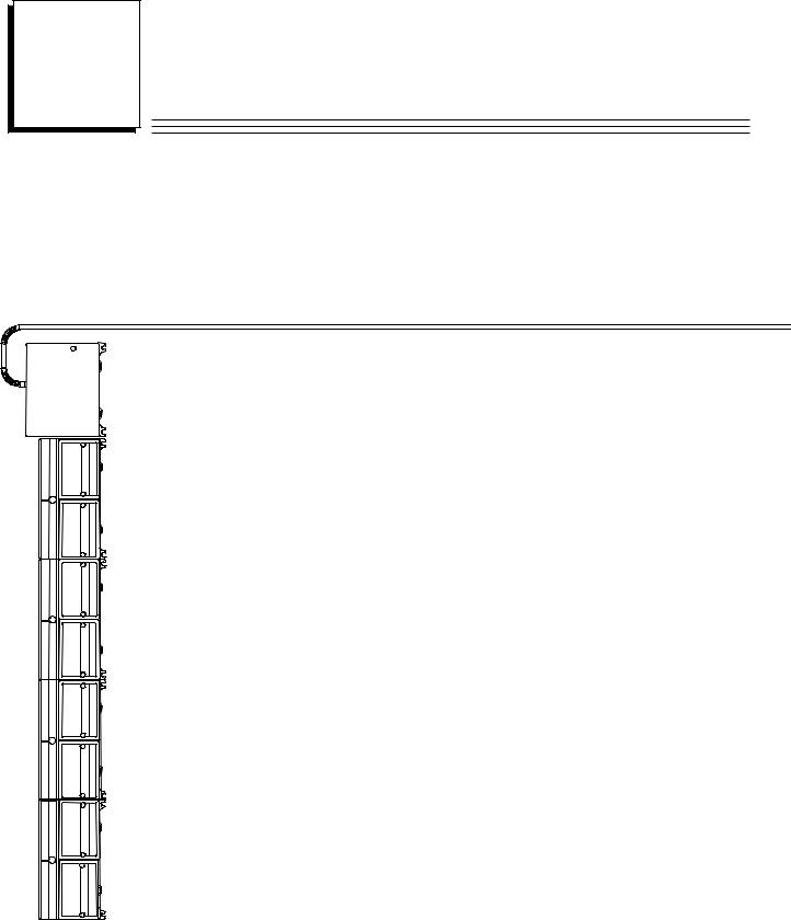
The heart of the Field Control system is the Bus Interface Unit. The Bus Interface Unit provides |
|
Unit |
||
|
intelligent processing, I/O scanning, and feature configuration for a group of up to eight I/O |
|
|
modules. Together, the Bus Interface Unit and its modules make up a Field Control station (see the |
|
I/O |
illustration, left). |
|
|
The Bus Interface Unit and I/O modules are enclosed in sturdy, compact aluminum housings. Bus |
|
|
Interface Unit and I/O modules bolt securely to separate Terminal Blocks, which provide all field |
|
I/O |
wiring terminals. The I/O Terminal blocks are generic and allow different I/O module types to be |
|
|
mounted on the same base. I/O Terminal Blocks are available with box-type terminals, barrier-type |
|
|
terminals, or wire-to-board connectors. All Terminal Blocks must be mounted on a DIN rail. The |
|
I/O |
DIN rail, which serves as an integral part of the grounding system, can also be mounted on a panel. |
|
|
|
|
|
Field Control Features |
|
I/O |
Features and benefits of Field Control include: |
|
|
|
|
|
T |
wiring savings |
|
T |
better up time |
I/O |
T easy installation and maintenance |
Tspare parts savings
T low cost
T feature flexibility
I/O
Topen architecture / adaptable to a variety of networks
T distributed I/O
Tsmall, compact I/O modules with generic terminal wiring bases.
I/O
TDIN rail mounted
I/O
GFK-0825F |
1-1 |

1 |
Field Control Modules
There are three basic types of Field Control modules:
S
S
S
S
Bus Interface Unit. The illustration below shows a Genius Bus Interface Unit.
I/O modules
Micro Field Processor
Terminal Blocks:
VBus Interface Unit Terminal Block.
VI/O Terminal Blocks, each of which accommodates two I/O modules.
VAuxiliary Terminal Blocks. These optional terminal strips can be connected to the side of an I/O Terminal Block if extra common terminals are needed.
Bus Interface Unit |
Genius |
|
Bus Interface Unit |
||
Terminal Block |
||
|
Micro
Field Processor
|
I/O Terminal |
Auxiliary |
Block |
Terminal Blocks |
I/O Modules |
1-2 |
Field Control™ Genius® Bus Interface Unit User’s Manual – October 1999 |
GFK-0825F |

1 |
Genius Bus Interface Unit
The Genius Bus Interface Unit (IC670GBI002 or IC697GBI102) interfaces Field Control I/O modules to a host PLC or computer via a Genius bus. It can exchange up to 128 bytes of input data and 128 bytes of output data with the host, each Genius bus scan. It can also handle Genius datagram communications.
The intelligent processing capabilities of the Genius Bus Interface Unit allow the configuration of features such as fault reporting, selectable input and output defaults, analog scaling and analog range selection for the modules in the station. In addition, the Genius Bus Interface Unit performs diagnostic checks on itself and its I/O modules, and relays diagnostic information to the host (if configured for fault reporting) and to a Hand-held Monitor.
The Genius Bus Interface Unit can be used on a bus controlled by redundant CPUs or Bus Controllers. It can also be used on a dual bus.
The Bus Interface Unit mounts on a Bus Interface Unit Terminal Block. It can be removed and replaced if necessary without removing the wiring or reconfiguring the I/O station.
Bus Interface Unit Terminal Block
The Bus Interface Unit Terminal Block, which included with the BIU, has connections for power wiring and single or dual communications cables. It has built-in bus switching circuitry, allowing the Bus Interface Unit to be used on a dual (redundant) Genius bus (no external Bus Switching Module is needed). The Bus Interface Unit Terminal Block stores the configuration parameters selected for the station.
I/O Modules
Field Control I/O Modules are available in many types to suit a wide range of application needs. Modules can be installed and removed without disturbing field wiring. One or two I/O modules may be mounted on an I/O Terminal Block.
Micro Field Processor
The Series 90 Micro Field Processor (MFP) is a Micro PLC that provides local logic within a Field Control station. The Micro Field Processor is the same size as a Field Control I/O module and occupies one of the eight available I/O slots in a Field Control station.
MFP features include:
SCompatible with Logicmaster 90-30/20/Micro programming software, revision 6.01 or later.
SAlarm processor
SPassword protection
SBuilt-in communications port that supports Series 90 protocols (SNP and SNPX)
The Micro Field Processor requires a Genius Bus Interface Unit revision 2.0 or later.
GFK-0825F |
Chapter 1 Introduction |
1-3 |

1 |
I/O Terminal Blocks and Auxiliary I/O Terminal Blocks
An I/O Terminal Block provides mounting, electrical, and field wiring connections. Each half of the I/O Terminal Block can be mechanically keyed to accept only an I/O module of a specific type. Auxiliary I/O Terminal Blocks can be easily attached to an I/O Terminal Block. They can be used to provide additional common terminals if needed.
For more information, please refer to:
Chapter 3: Installation, which explains wiring to the Bus Interface Unit, and explains how to install the Bus Interface Unit module on the Field Terminal Block.
Chapter 2: Description, which describes the Bus Interface Unit and Bus Interface Unit Terminal Block in detail.
Chapter 4, Operation, which explains how the Genius Bus Interface Unit services I/O.
Chapter 5: Hand-Held Monitor Configuration, which explains how to configure I/O modules.
The Series 90 Micro Field Processor User's Manual (GFK-1171), which describes the Micro Field Processor (IC670MFP100) and provides installation procedures, operation information, and diagnostics information.
The Field Control I/O Modules User's Manual (GFK-0826) which describes I/O modules and I/O Terminal Blocks. This manual also explains module installation and field wiring.
1-4 |
Field Control™ Genius® Bus Interface Unit User’s Manual – October 1999 |
GFK-0825F |

1 |
Environmental Specifications
Vibration |
Modules perform well where vibration is a factor. Designs are shock and |
|
|
vibration tested to meet the following specifications when installed on a |
|
|
panel-mounted DIN rail using the clamp supplied, and with the panel- |
|
|
mounting feet secured: |
|
|
IEC68-2-6: |
10 to 57 Hz 0.012 in displacement (peak to peak) |
|
|
57 to 500 Hz at 2 g (unless otherwise specified) |
|
IEC68-2-27: |
Shock: 15G, 11 milliseconds, half sine wave |
Noise |
Modules are resistant to noise levels found in most industrial applications |
|
|
when installed according to accepted practices, including proper separation |
|
|
of wiring by voltage and power levels, on a conductive (unpainted) DIN rail. |
|
|
The DIN rail is an integral part of the grounding system. |
|
Modules are tested to the specifications listed in the Conformance to
Standards document (GFK-1079).
Temperature Modules operate reliably in ambient air temperatures from 0 deg. C (32 deg. F) up to 55 deg. C (131 deg. F).
Storage temperatures are -40 deg. C (-40 deg. F) to +85 deg. C (185 deg. F).
Humidity |
5% to 95%, non-condensing. |
For information about installing Field Control modules, please see:
Chapter 2 of this manual. It describes installation and wiring for the Bus Interface Unit module and terminal block.
Chapter 2 of the Field Control I/O Modules User's Manual. It summarizes installation instructions for modules and terminal blocks.
The individual module datasheets included in the Field Control I/O Modules User's Manual, which provide specific module wiring information.
Chapter 2 of the Genius I/O System and Communications User's Manual, which includes detailed instructions for selecting and installing a Genius bus.
GFK-0825F |
Chapter 1 Introduction |
1-5 |

1 |
Configuration for Field Control
Configuration is an important part of the process of setting up a Field Control station. It establishes the following features:
TFor the Bus Interface Unit:
V Genius serial bus address
V Baud rate for Genius bus communications
V Fault reporting to the host
V Use of the Bus Interface Unit as a bus switching device in a dual (redundant) bus system
V Redundancy mode for CPU redundancy
V Configuration protection
TFor I/O Modules:
V I/O addressing
V Whether faults will be reported to the host
V Hold Last State for inputs or outputs
V Output defaults
V Range selection for analog modules
V Scaling for analog modules
V Alarm limits for analog modules
TFor a Micro Field Processor:
V Reference addresses
V Data Lengths
A Bus Interface Unit and I/O modules can be fully configured using a Hand-held Monitor.
Optionally, a previously-configured Bus Interface Unit can be reconfigured using datagrams.
For more information about configuration, please refer to:
Chapter 5 of this manual (HHM Configuration). A Genius Hand-held Monitor, version 4.6 (IC660HHM501J ) or later, can be used to configure a Bus Interface Unit. HHM configuration instructions are given in chapter 5.
In addition, chapter 8 of this manual (Datagrams) explains how the configuration of a Bus
Interface Unit can be completed or changed by sending it Write Configuration datagrams.
The Series 90 Micro Field Processor User's Manual (GFK-1171), which describes the Micro Field Processor (IC670MFP100), and provides installation procedures, operation information, and diagnostics information.
If the system host is a Series 90™70 PLC, the Genius Bus Interface Unit must be included in the system configuration as a device on the bus. Please see the programming software documentation for instructions.
1-6 |
Field Control™ Genius® Bus Interface Unit User’s Manual – October 1999 |
GFK-0825F |

1 |
Field Control in a Genius System
Using Field Control modules on a Genius bus combines the low cost, small size, and flexibility of Field Control with the versatility, power, and communications features of the Genius system.
The Genius bus is an industrially-hardened Local Area Network (LAN). It passes I/O (control) data and background information (datagrams) between the Bus Interface Unit and a Genius bus controller. A Genius bus can support up to 32 devices. Each Bus Interface Unit station counts as one device on the bus, regardless of the number or type of modules present in the station.
Other devices on the same bus can be Field Control stations, remote drops, I/O blocks, Bus Controllers and Hand-held Monitors. Typical busses reserve one location for a Bus Controller and one for a Hand-held Monitor, leaving 30 for additional devices. The illustration below shows a Series 90-70 PLC connected to a Genius bus with I/O blocks and two Field Control stations.
Series 90-70 PLC
Hand-held
Monitor
Genius Bus
The Host CPU
The Genius Bus Interface Unit is ideally suited for use with a Series 90-70 or Series 90-30 PLC. However, any type of PLC or computer capable of controlling a Genius bus can be used as the host. Possible hosts include Series Six PLCs, Series Five PLCs, and computers equipped with a PCIM (Personal Computer Interface Module), QBIM (Q-Bus Interface Module), or a third-party GENIbased interface module, including several in DCS systems.
GFK-0825F |
Chapter 1 Introduction |
1-7 |
1 |
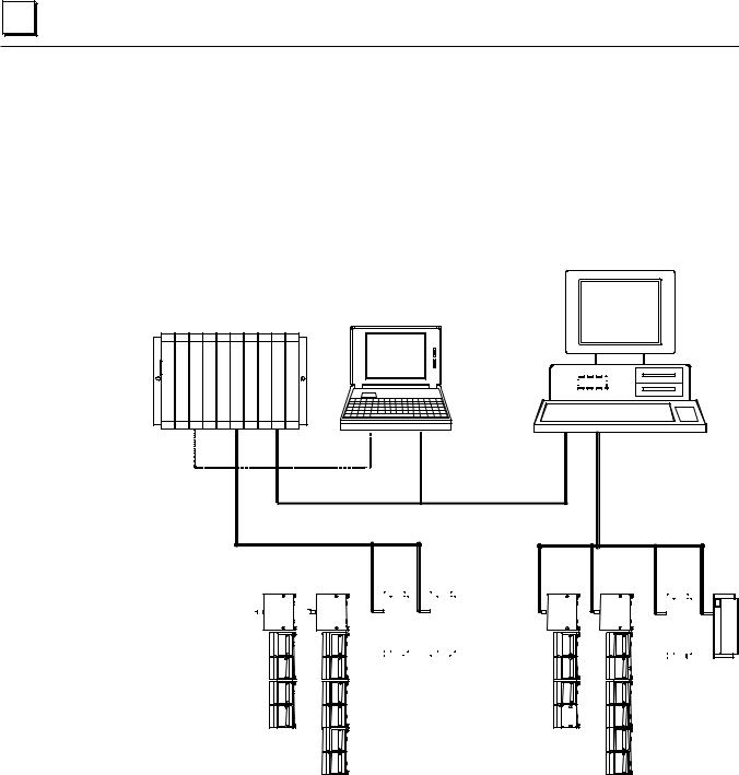
A More Complex Field Control and Genius System
A more complex communications and control system is illustrated below. In this system, the Field Control stations and Genius blocks on the lower left are controlled by a Series 90-70 PLC. The Field Control stations and Genius blocks on the lower right are controlled by a host computer equipped with a PCIM (Personal Computer Interface Module).
The PLC communicates with a computer running programming software via an SNP (Serial Network Protocol) link. And the PLC, host computer, and programmer computer exchange system data via an Ethernet communications link.
Series 90-70 PLC

 PCIM
PCIM 
SNP
Ethernet
|
|
|
|
|
Genius Bus |
|
|
|
|
|
|
|
|
|
|
|
|
|
|
|
|
|
|
|
|
|
Genius Bus |
|
||||||||||||
|
|
|
|
|
|
|
|
|
|
|
|
|
|
|
|
|
|
|
|
|
|
|
|
|
|
|
|
|
|
|
|
|
|
|
|
|
|
|
|
|
|
|
|
|
|
|
|
|
|
|
|
|
|
|
|
|
|
|
|
|
|
|
|
|
|
|
|
|
|
|
|
|
|
|
|
|
|
|
|
|
|
|
|
|
|
|
|
|
|
|
|
|
|
|
|
|
|
|
|
|
|
|
|
|
|
|
|
|
|
|
|
|
|
|
|
|
|
|
|
|
|
|
|
|
|
|
|
|
|
|
|
|
|
|
|
|
|
|
|
|
|
|
|
|
|
|
|
|
|
|
|
|
|
|
|
|
|
|
|
|
|
|
|
|
|
|
|
|
|
|
|
|
|
|
|
|
|
|
|
|
|
|
|
|
|
|
|
|
|
|
|
|
|
|
|
|
|
|
|
|
|
|
|
|
|
|
|
|
|
|
|
|
|
|
|
|
|
|
|
|
|
|
|
|
|
|
|
|
|
|
|
|
|
|
|
|
|
|
|
|
|
|
|
|
|
|
|
|
|
|
|
|
|
|
|
|
|
|
|
|
|
|
|
|
|
|
|
|
|
|
|
|
|
|
|
|
|
|
|
|
|
|
|
|
|
|
|
|
|
|
|
|
|
|
|
|
|
|
|
|
|
|
|
|
|
|
|
|
|
|
|
|
|
|
|
|
|
|
|
|
|
|
|
|
|
|
|
|
|
|
|
|
|
|
|
|
|
|
|
|
|
|
|
|
|
|
|
|
|
|
|
|
|
|
|
|
|
|
|
|
|
|
|
|
|
|
|
|
|
|
|
|
|
|
|
|
|
|
|
|
|
|
|
|
|
|
|
|
|
|
|
|
|
|
|
|
|
|
|
|
|
|
|
|
|
|
|
|
|
For more information about Genius systems and communications, please refer to:
The Genius I/O System and Communications User's Manual, which describes Genius system operation, and communications formats.
The Bus Controller User's Manual for the system host, which includes specific system interface instructions.
1-8 |
Field Control™ Genius® Bus Interface Unit User’s Manual – October 1999 |
GFK-0825F |

1 |
Required Genius and Host System Equipment
The following system equipment is required:
TGenius Hand-held Monitor version 4.6 (IC660HHM501J) or later.
TFor a Series 90-70 PLC
VSeries 90-70 CPU firmware, release 3.0 or later.
VA Series 90-70 Genius Bus Controller, release 3.0 or later. The Bus Controller must be 4.0 or later for full diagnostics display from Logicmaster 90-70, or for redundancy applications.
VIf Logicmasterä 90-70 programming and configuration software is used, it must be release 3.0 or later:
A. IC641SWP701F (3.5", 2DD, 5.25" 2S/HD)
B. IC641SWP704C (5.25" 2S/2D)
T For a Series 90 30 PLC
VSeries 90 30 CPU firmware: any version.
VLogicmasterä 90-30 programming and configuration software: any version.
VSeries 90-30 Genius Bus Controller: any version.
T For a Series Six™ PLC
VCPU: rev. 105 or later.
VLogicmaster 6 Programming Software: release 4.02 or later.
VBus Controllers: IC660CBB902 or 903, version 1.7 or later.
T For a Series Five™ PLC
VCPU: rev. 3.2 (catalog number with E suffix) or later.
VLogicmaster 5 Programming Software: release 2.01 or later.
VBus Controller: any version
T For a Host Computer
VPCIM: any version
VQBIM: any version
GFK-0825F |
Chapter 1 Introduction |
1-9 |

1 |
Using Field Control in a CPU Redundancy System
Most systems use only one Bus Controller and CPU to control the I/O on the Genius bus. CPU redundancy, which can be used for backup CPU/Bus Controller protection in critical applications, is described in detail in the Genius documentation. The section that follows here summarizes how Field Control products can fit into a Genius CPU Redundancy system.
CPU/Bus Controller Redundancy: Overview
In CPU redundancy, two Bus Controllers on the same bus can send control outputs at the same time. Both Bus Controllers automatically receive inputs and fault reports from all devices on the bus that have been configured as being in “CPU Redundancy” mode. The Bus Controllers must use serial bus addresses (device numbers) 30 and 31.
Field Control stations can be used on a bus controlled by redundant CPUs/Bus Controllers.
Bus |
|
|
Bus |
|
|
46471 |
||||||||||||||||||||||
|
|
|
|
|
|
|
|
|
|
|
|
|
|
|
|
|
|
|
|
|
|
|
|
|
||||
Controller |
|
Controller |
|
|
|
|
|
|
|
|
|
|
|
|
|
|
|
|
|
|
|
|
|
|||||
(Device |
30) |
|
(Device |
31) |
|
|
|
|
|
|
|
|
|
|
|
|
|
|
|
|
|
|
|
|
|
|||
|
|
|
|
|
|
|
|
|
|
|
|
|
|
|
|
|
|
|
|
|
|
|
|
|
|
|
|
|
|
|
|
|
|
|
|
|
|
|
|
|
|
|
|
|
|
|
|
|
|
|
|
|
|
|
|
|
|
|
|
|
|
|
|
|
|
|
|
|
|
|
|
|
|
|
|
|
|
|
|
|
|
|
|
|
|
|
|
|
|
|
|
|
|
|
|
|
|
|
|
|
|
|
|
|
|
|
|
|
|
|
|
|
|
|
|
|
|
|
|
|
|
|
|
|
|
|
|
|
|
|
|
|
|
|
|
|
|
|
|
|
|
|
|
|
|
|
|
|
|
|
|
|
|
|
|
|
|
|
|
|
|
|
|
|
|
|
|
|
|
|
|
|
|
|
|
|
|
|
|
|
|
|
|
|
|
|
|
|
|
|
|
|
|
|
|
|
|
|
|
|
|
|
|
|
|
|
|
|
|
|
|
|
|
|
|
|
|
|
|
|
|
|
|
|
|
|
|
|
|
|
|
|
|
|
|
|
|
|
|
|
|
|
|
|
|
|
|
|
|
|
|
|
|
|
|
|
|
|
|
|
How the two sets of outputs from the dual CPUs are handled by a Bus Interface Unit depends on whether the Bus Interface Unit is set up for Hot Standby or Duplex redundancy. If the station contains any analog modules, the only form of CPU redundancy permitted is Hot Standby.
Hot Standby CPU Redundancy
A Bus Interface Unit configured for Hot Standby mode is normally controlled by the Bus Controller assigned to serial bus address 31. If no outputs are available from 31 for three bus scans, the Bus Interface Unit accepts outputs from the Bus Controller assigned to serial bus address 30. If outputs are not available from either Bus Controller, outputs go to their configured defaults or hold their last state. In Hot Standby redundancy, Bus Controller-31 always has priority; when it is on-line, it has control of the outputs.
Duplex CPU Redundancy
A Bus Interface Unit configured for Duplex mode compares outputs it receives from the two Bus Controllers, to determine if they match. If corresponding outputs are the same, the Bus Interface Unit sets the output to that state. If corresponding outputs are not the same, the Bus Interface Unit sets the output to its configured ON or OFF Duplex Default State. If either Bus Controller stops sending outputs to a Bus Interface Unit, its outputs are directly controlled by the remaining Bus Controller. Only discrete I/O modules can operate in Duplex redundancy mode; do not use Duplex mode if the station contains any analog I/O modules.
1-10 |
Field Control™ Genius® Bus Interface Unit User’s Manual – October 1999 |
GFK-0825F |

1 |
Using Field Control in a Genius Bus Redundancy System
In Genius bus redundancy, there are two bus cables each connected to a Bus Controller. I/O devices may be connected to either one bus of the pair, or to both. However, a device that is connected to both busses actually communicates on only one bus at a time. Before the alternate bus can be used for communications, a bus switchover must occur and the device must “log in” with the Bus Controller(s) on the alternate bus.
The Bus Interface Unit Terminal Block contains a built-in bus switching relay that is used to switch busses in a dual bus system. Other types of devices with this capability are dedicated Bus Switching Modules and Series 90-70 Remote I/O Scanner modules. These are the only types of devices that can be directly connected to both redundant bus cables.
A Bus Interface Unit cannot be used as the BSM Controller for a bus stub. Other devices cannot be located on a stub downstream of a BIU.
Also, the Bus Interface Unit should not be connected to an external Bus Switching Module.
Redundant Bus Configurations
Many different redundant bus configurations are possible. Three basic ways of using a Bus Interface Unit with a redundant bus are described below.
TA Bus Interface Unit can be installed directly on both cables of the dual bus pair. The Bus Interface Unit is configured to operate as a bus switching device in addition to performing its normal functions. Here, two Field Control stations are installed on a dual bus. Each Bus Interface Unit would be set up as a bus switching device.
Bus A |
46472 |
Bus B
TA Bus Interface Unit can be located on just one bus of a redundant bus pair, if bus redundancy is not needed for the modules in that station. In this example, the Bus Interface Unit on the left is connected to both Bus A and Bus B and is configured as a bus switching device. The Bus Interface Unit on the right, which serves non-critical I/O modules, is connected to Bus A only, and is not configured as a bus switching device.
Bus A |
46473 |
Bus B
GFK-0825F |
Chapter 1 Introduction |
1-11 |
1 |
TA Bus Interface Unit can be located on a bus stub. A Bus Interface Unit can also be located on a bus stub, which is a short length of unterminated cable downstream of either a Genius I/O block/Bus Switching Module combination, or a Remote I/O Scanner connected to a dual bus.
Because the bus stub cable itself is not redundant, this type of installation does not provide as much protection as connecting directly to a dual bus. The bus switching device to which the bus stub is connected can be another Genius block with a Bus Switching Module attached, as shown below, or a Series 90-70 Remote I/O Scanner.
In this example, there are two Field Control stations installed on a bus stub. Each is configured as “BSM Present” but not configured as a “BSM Controller”.
Bus A |
46474 |
Bus B
Bus
Switching
Module
Genius Block |
|
|
Acting as a |
Up to 7 Additional Devices on the Bus Stub |
|
BSM Controller |
||
|
Up to seven devices (not counting the BSM/block or Remote I/O Scanner to which the dual bus is connected) can be installed on a bus stub. Each device on a bus stub counts toward the total of 32 devices on the Genius bus.
Restrictions on the number and length of bus stubs that may be used on a dual bus are explained in the Genius I/O System and Communications User's Manual.
1-12 |
Field Control™ Genius® Bus Interface Unit User’s Manual – October 1999 |
GFK-0825F |

Chapter Description
2
This chapter describes:
SGenius Bus Interface Unit
SBus Interface Unit Power Supply
SBus Interface Unit Terminal Block
SSpecifications
Genius Bus Interface Unit
The Genius Bus Interface Unit is a small, rugged, intelligent module with a sturdy aluminum housing. The module has four status LEDs, described below, and a connector for attaching a Genius Hand-held Monitor.
3.25" (8.2mm)
HHM
Connector
5.0" (12.7mm)
LEDs
The Bus Interface Unit contains the logic power supply needed to operate the I/O modules connected to it. It mounts on a separate terminal block, to which it and all bus wiring are attached. The configuration is stored in non-volatile memory located in the terminal block. Both the power supply and terminal block are described in this chapter.
The Bus Interface Unit has a replaceable 1A, 5x20mm 250VAC slow-blow fuse on the input power lines. The fuse can be changed without disturbing the wiring of any other modules (instructions are in chapter 3).
GFK-0825F |
2-1 |

2 |
LEDs
The LEDs on the Bus Interface Unit show its operating status.
RUN |
B BUS ACTIVE |
OK |
PWR |
PWR |
lights to indicate that +5V power is available for logic operation. |
||
OK |
lights to indicate that the module has passed its powerup diagnostic tests. |
||
|
See the table below for more information. |
||
RUN |
lights only if output modules are in the BIU configuration and are written |
||
|
to by the controlling bus controller. See the table below. |
||
BUS B |
if the Bus Interface Unit is installed on a dual (redundant) bus, this LED |
||
|
lights if Bus B is the currently-active bus. |
||
|
|
|
|
OK |
RUN |
|
Meaning |
|
|
|
|
ON |
ON |
Module functioning, CPU communicating |
|
|
|
|
|
ON |
OFF |
Module functioning, no CPU communications for 3 bus scans |
|
|
|
|
|
ON |
Blinking |
Module functioning, circuit forced |
|
|
|
|
|
Blinking |
ON |
Circuit |
fault, CPU communicating |
|
|
|
|
Blinking |
OFF |
Circuit |
fault, no CPU communications for 3 bus scans |
|
|
|
|
Alternate Blinking |
Circuit fault, Circuit forced |
||
|
|
|
|
Synchronous |
Blinking |
No CPU communications - block number conflict |
|
|
|
|
|
OFF |
Blinking |
Electronics/Terminal Assembly mismatch |
|
|
|
|
|
OFF |
OFF |
No block power, or Block faulty |
|
|
|
|
|
2-2 |
Field Control™ Genius® Bus Interface Unit User’s Manual – October 1999 |
GFK-0825F |

2 |
Bus Interface Unit Power Supply
The power supply in the Bus Interface Unit provides power for the Bus Interface Unit itself and logic power for all I/O modules that may potentially be installed at that station. External power must be supplied for field wiring of input and output devices.
The power supply is not damaged by either of the following:
S
S
Reversing input voltage on terminals 1 and 2.
Temporary overcurrent conditions on the 6.5 VDC output.
Timing
The Bus Interface Unit provides power to all I/O modules that are installed at the station. I/O module operation is governed by a System Reset signal to ensure controlled operation during the power up and shut down processes. As shown in the timing diagram below, momentary power losses of less than 10 mS (for 24VDC BIU) or 20mS (for 115VAC/125VDC BIU) do not affect I/O module operation. Longer power losses generate a Reset for all system I/O modules.
|
Input Power |
|
|
|
|
Momentary |
|
|
|
|
Input Power |
||||||||||||||||||||||
24VDC |
On |
|
|
|
|
|
|
|
|
Off |
|||||||||||||||||||||||
|
|
|
|
|
|
Power |
|
|
|
|
|
||||||||||||||||||||||
Nominal |
|
|
|
|
|
|
|
|
|
|
|
|
|
|
|
|
|
|
|
|
|
|
|
|
|
|
|
||||||
|
|
|
|
|
|
|
|
|
|
|
|
|
|
|
|
Loss |
|
|
|
|
|
|
|
|
|
|
|
|
|||||
or 115 VAC |
|
|
|
|
|
|
|
|
|
|
|
|
|
|
|
|
|
|
|
|
|
|
|
|
|||||||||
Nominal |
|
|
|
Voltage |
|
|
|
|
|
|
|
|
|
|
|
|
|
|
|
Voltage |
|
|
|
|
|
|
|
||||||
|
|
|
Overshoot |
|
|
|
|
|
|
|
|
|
|
|
Overshoot |
|
|
|
|
|
|
|
|||||||||||
|
|
|
5% (max) |
|
|
|
|
|
|
|
|
|
|
|
5% (max) |
|
|
|
|
|
|
|
|||||||||||
|
|
|
|
|
|
|
|
|
|
|
|
|
|
|
|
|
|
|
|
|
|
|
|
|
|
|
|
|
|
|
|
|
|
|
|
|
|
|
|
|
|
|
|
|
|
|
|
|
|
|
|
|
|
|
|
|
|
|
|
|
|
|
|
|
|
|
|
6.5V Output |
|
|
|
95% (min) |
|
|
|
Hold |
|
|
|
|
|
|
Hold |
||||||||||||||||||
|
|
|
|
|
|
|
|
|
|
||||||||||||||||||||||||
|
|
|
|
|
|
|
|
|
|
||||||||||||||||||||||||
|
|
|
|
|
|
|
|
|
|
|
|
|
|
|
|
|
|
|
|||||||||||||||
|
|
|
|
|
|
|
|
|
|
|
|
|
|
|
|
|
Up |
|
|
|
|
|
|
|
|
Up |
|
||||||
|
|
|
|
|
|
|
|
|
|
|
|
|
|
|
|
|
|
|
|
|
|||||||||||||
|
|
|
|
|
|
|
|
|
|
Minimum: |
|
|
|
Time |
|
|
|
|
|
|
Time |
||||||||||||
|
|
200mS |
|
|
|
|
|
|
|
|
|
|
|
|
|
200mS |
|
10mS |
|||||||||||||||
|
|
|
(min) |
|
|
|
|
|
10mS for 24VDC BIU |
|
|
|
|
|
|
|
|
|
|
|
(min) |
|
|
|
(min) |
|
|||||||
|
|
|
|
|
|
|
20mS for 115VAC/125VDC BIU |
|
|
|
|
|
|
|
|
|
|
|
|
||||||||||||||
|
|
|
|
|
|
|
|
|
|
|
|
|
|
|
3mS |
|
|
|
|
|
|
3mS |
|
|
|||||||||
|
|
|
|
|
|
|
|
|
|
|
|
|
|
(min) |
|
|
|
|
(min) |
||||||||||||||
|
|
|
|
|
|
|
|
|
|
|
|
|
|
|
|
|
|
|
|
|
|
|
|
|
|
|
|
|
|
|
|
|
|
RST*
GFK-0825F |
Chapter 2 Description |
2-3 |

2 |
Backplane Current
With a DC input voltage, the amount of current available to the backplane may be limited by lower input voltage as indicated below.
|
For 24VDC Supply |
|
For 125VDC Supply |
||
Backplane |
1.4 |
|
|
Backplane |
2.0 |
Current |
1.2 |
|
|
Current |
1.8 |
Available |
1.0 |
|
|
Available |
|
(Amps) |
|
|
|
(Amps) |
|
|
18 |
19 |
21 |
|
105 110 |
|
|
Voltage In |
|
Voltage In |
|
Calculating Input Power Requirements for a Bus Interface Unit
The charts below show typical input power requirements for a Bus Interface Unit.
|
For 24VDC Bus Interface Unit |
For 115VAC/125VDC Bus Interface Unit |
|
|||||||||||
|
15.9 |
|
|
|
|
|
|
24.0 |
|
|
|
48.0 |
|
|
|
|
|
|
|
|
|
|
|
|
|
||||
|
|
|
|
|
|
|
|
|
|
|
|
|
||
|
14.1 |
|
|
|
|
|
Typical |
|
|
|
|
37.75 |
Typical |
|
|
|
|
|
|
|
|
|
|
|
Input |
||||
Typical |
12.3 |
|
|
|
|
|
Input |
18.75 |
|
|
|
|
|
|
|
|
|
|
|
Power |
|
|
|
|
|
Power |
|||
|
|
|
|
|
|
|
|
|
27.5 |
|||||
Input |
10.0 |
|
|
|
|
|
(Watts) |
13.5 |
|
|
|
(Volt/Amps) |
||
Power |
|
|
|
|
|
for DC |
|
|
|
|
|
for AC |
||
(Watts) |
7.7 |
|
|
|
|
|
Inputs |
|
|
|
|
17.25 |
Inputs |
|
|
|
|
|
|
|
|
8.25 |
|
|
|
|
|||
|
|
|
|
|
|
|
|
|
|
|
|
|||
|
5.5 |
|
|
|
|
|
|
|
|
|
|
|
|
|
|
|
|
|
|
|
|
|
|
|
|
|
7.0 |
|
|
|
3.4 |
|
|
|
|
|
|
3.0 |
|
|
|
|
|
|
|
|
|
|
|
|
|
|
|
|
|
|
|||
|
|
|
|
|
|
|
|
|
|
|
|
|
||
|
0 |
0.25 |
0.50 |
0.75 |
1.00 |
1.20 |
1.40 |
|
|
|
|
|
|
|
|
0 |
0.50 |
1.00 |
1.50 |
2.0 |
|
||||||||
|
|
Total Backplane Current |
(Amps) |
|
Total Backplane Current (Volts) |
|
|
|
||||||
Note
For a 24VDC Bus Interface Unit, start-up surge at full load is 15-50 Amps for 3 milliseconds (maximum). For a 115VAC/125VDC Bus Interface Unit, startup surge at full load is 20 Amps peak for 3mS.
To determine specific system requirements:
SDetermine total output load from typical specifications listed for individual modules.
SUse the appropriate graph of input power above to determine average input power.
SDivide the input power by the operating source voltage to determine the input current requirements.
SUse the lowest input voltage to determine the maximum input current.
SAllow for startup surge current requirements. Startup surge current levels are a function of source impedance and, therefore, are installation-dependent. Startup surge currents can vary for approximately 3mS. For the 24VDC Bus Interface Unit, variance is between 25A and 50A. For the 115VAC/125VDC Bus Interface Unit, startup surge current is 20A maximum peak.
SAllow margins (10% to 20%) for variations.
2-4 |
Field Control™ Genius® Bus Interface Unit User’s Manual – October 1999 |
GFK-0825F |

2 |
Bus Interface Unit Power Dissipation
The Bus Interface Unit power dissipation can be determined once the backplane current supplied to the I/O modules is known.
The following equation can be used to calculate BIU power dissipation:
BIU Power Dissipation = Input Power - (total backplane current x 6.5 volts)
For example:
A.Total backplane current = 0.5 Amps
B.Typical Input power = 7.7 Watts
Therefore:
BIU Power Dissipation = 7.7 W - ( 0.5 x 6.5 ) = 4.45 Watts
GFK-0825F |
Chapter 2 Description |
2-5 |

2 |
Load Requirements for Hardware Components
The table below shows the DC load required by each module and hardware component. All ratings are in milliamps. Input and Output module current ratings are with all inputs or outputs on. These are maximum requirements, not typical.
Catalog Number |
Description |
Current (mAmps) |
IC670MDD441 |
Mixed I/O Module, 24 VDC 10 Inputs, 6 Outputs |
110 |
IC670MDL233 |
Input Module, 120 VAC 8 Isolated Points |
40 |
IC670MDL240 |
Input Module, 120 VAC 16 Grouped Points |
77 |
IC670MDL241 |
Input Module, 16 Points, 2 groups 240 VAC |
77 |
IC670MDL640 |
Input Module, 24 VDC 16 Grouped Pos/Neg Points |
83 |
IC670MDL641 |
Input Module, 48 VDC 16 Grouped Pos/Neg Points |
83 |
IC670MDL642 |
Input Module, 125 VDC 16 Grouped Pos/Neg Points |
77 |
IC670MDL643 |
Input Module, 5/12 VDC 16 Point |
80 |
IC670MDL644 |
Input Module, 12/24 VDC 16 Grouped Pos/Neg Fast Inputs |
80 |
IC670MDL730 |
Output Module, 8 Pt 24 VDC Electronic Short Circuit Protection |
125 |
IC670MDL740 |
Output Module, 12/24 VDC 0.5 Amp, 16 Grouped Pos. |
111 |
IC670MDL742 |
Output Module, 5/12/24 VDC Negative Outputs |
111 |
IC670MDL330 |
Output Module, 16 Point 12-120 VAC 16 Pt 1.0 Amp |
285 |
IC670MDL331 |
Output Module, 120 VAC 2 Amp, 8 Isolated Points |
154 |
IC670MDL930 |
Relay Output Module, 2 Amp, 6 Form A Points and 2 Isolated |
313 |
|
Form C Points |
|
IC670ALG230 |
Analog Current Input Module, 8 Grouped Points |
51 |
IC670ALG240 |
Analog Input Module, 16 point Grouped |
251 |
IC670ALG281 |
Analog Voltage Input Module, 8 Grouped Points |
150 |
IC670ALG282 |
Analog Voltage Input Module, 16Grouped Points |
150 |
HE670ACC100 |
Input Simulator Module, Horner |
100 |
HE670ADC810 |
Analog Input Module, Horner, +/-10VDC, 0-10 VDC |
131 |
IC670ALG620 |
RTD Input Module |
190 |
IC670ALG630 |
Thermocouple Input Module |
195 |
IC670ALG320 |
Analog Current/Voltage Output Module, 4 Grp Points |
51 |
IC670ALG330 |
Analog Current source Output Module, 8 Points |
85 |
IC670MFP100 |
Micro Field Processor |
111 |
IC693PRG300 |
Hand-held Programmer |
170 |
|
|
|
IC660HHM501 |
Genius Hand-held Monitor |
0 |
Hand-held Monitor and Hand-held Programmer
The Genius Hand-held Monitor (IC660HHM501), used for configuring and monitoring the BIU, has its own battery and does not add to the load on the BIU.
However, if a Hand-held Programmer (IC693PRG300) will be attached to a Micro Field Processor or other module in the I/O Station, it must be considered as a load component as listed above.
2-6 |
Field Control™ Genius® Bus Interface Unit User’s Manual – October 1999 |
GFK-0825F |

2 |
Hot Insertion/Removal of Modules
Bus Interface Units IC670GBI002(F) and IC670GBI102A or later support Hot Insertion/Removal of modules in the I/O Station.
Hot Insertion/Removal means that modules can be removed and replaced while I/O Station power is applied without affecting the BIU or other modules in the I/O Station. Separate I/O module power must be switched off to the module being inserted or removed.
Hot Insertion/Removal requires the use of specific modules and I/O terminal blocks:
•I/O modules having catalog number suffix J or above. These modules have a projecting alignment tab that fits into a corresponding alignment tab on I/O Terminal Blocks listed below. Note that modules with this tab can also be installed on older I/O Terminal Blocks that do not have mating alignment tabs. However, Hot Insertion/Removal are not supported in such an installation.
•I/O Terminal Blocks IC670CHS101, 102, or 103. These I/O Terminal Blocks have projecting alignment tabs designed to facilitate Hot Insertion/Removal of modules. Modules that are earlier than revision J cannot be mounted on these terminal blocks.
I/O Terminal Blocks IC670CHS001, 002, and 003, which lack alignment tabs, do not support Hot Insertion/Removal of modules. With these terminal blocks, I/O Station power should be off when installing or removing modules.
Mixing IC670CHS10x terminal blocks with IC670CHS00x terminal blocks in the same I/O station is not recommended.
Faults Reported During Hot Insertion/Removal
When using the recommended equipment listed above, Hot Insertion/Removal will cause the expected fault reports related to the loss of or addition of the module and its I/O circuits. These faults should be cleared in the normal manner. However, Hot Insertion/Removal of a rev. J or later module will NOT cause Configuration Mismatch errors that in some types of systems can shut down the controller.
I/O Module Data During Hot Insertion/Removal
As mentioned, separate I/O module power must be turned off for Hot Insertion/Removal. When the module is installed and power is reapplied, module data will quickly return to normal. For intelligent I/O modules, there may be a delay of a few seconds while the module goes through its powerup sequence.
Hot Insertion/Removal for a Micro Field Processor
A Micro Field Processor that is revision J or later may be removed/inserted as described above. Note, however, that although the Micro Field Processor will start functioning upon reinstallation, the MFP's application program must be reloaded. I/O data controlled by the Micro Field Processor will be incorrect until that has been done. (The BIU configuration of the Micro Field Processor is not affected by Hot Insertion/Removal).
Hot Insertion/Removal Not Permitted in Hazardous Locations
In hazardous locations, I/O Station power must be turned off before inserting/removing module. Failure to observe this precaution may result in personal injury, system malfunction and/or damage to the equipment.
GFK-0825F |
Chapter 2 Description |
2-7 |
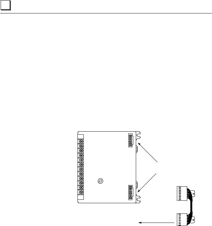
2 |
Bus Interface Unit Terminal Block
The Bus Interface Unit provides terminals for power and ground connections. Maximum wire size is AWG #14. (avg 2.0690mm2 cross-section).
The Bus Interface Unit Terminal Block also has eight input terminals for connection to a single or dual Genius bus. These terminals accommodate up to two AWG #14 wires. The Bus Interface Unit Terminal Block contains bus-switching circuitry permitting it to be used as a BSM Controller in a dual bus redundancy system.
A connecting cable is provided with each I/O Terminal Block. It is used to connect the Bus Interface Unit Terminal Block to the first I/O Terminal Block. The same type of cable interconnects subsequent I/O Terminal Blocks. The cable has molded connectors that are keyed to assure proper orientation.
The Bus Interface Unit Terminal Block is designed to be extremely reliable; it should not be necessary to replace or rewire it after installation.
The Bus Interface Unit Terminal Block stores the configuration parameters for the station. The Bus Interface Unit can be removed without removing the wiring or reconfiguring the station.
46457
Terminals for |
|
|
|
power and |
|
|
|
communications |
I/O Terminal Block |
|
|
wiring |
|
||
Connectors |
Connecting |
||
|
|||
|
|
||
|
|
Cable |
to next terminal block
2-8 |
Field Control™ Genius® Bus Interface Unit User’s Manual – October 1999 |
GFK-0825F |

2 |
Functional Specifications
Bus Interface Unit:
|
Reliability |
More than 183,000 hours operation MTBF, calculated |
||
|
24VDC Power Supply Input |
|
|
|
|
Nominal Rated Voltage |
24 VDC |
||
|
Voltage Range |
18 VDC to 30 VDC |
||
|
Power |
16.8 |
Watts maximum at full load (nominal voltage) |
|
|
Inrush Current |
15-50 |
Amps peak, 3 mS maximum. Inrush current is installation |
|
|
|
dependent. See page 2-4. |
||
|
Power Supply Output |
6.5 VDC ±5% |
||
|
to I/O modules: |
1.4 Amp maximum. See page 2-4. |
||
|
|
|||
|
Holdup Time |
10mS maximum from nominal input voltage. |
||
|
|
|
|
|
|
115VAC/125VDC Power Supply Input |
|
|
|
|
Nominal Rated Voltage |
115 VAC, 125 VDC |
||
|
Voltage Range |
90 to 135 VAC, 105 to 150 VDC |
||
|
Frequency (AC) |
47 to 63 Hz |
||
|
Power |
115 VAC: 48VA maximum at full load (nominal voltage) |
||
|
|
125 VAC: 24W maximum at full load (nominal voltage) |
||
|
Inrush Current |
20 Amps peak, 3 mS maximum. |
|
|
|
|
|||
|
Power Supply Output |
6.5 VDC ±5% |
|
|
|
to I/O modules: |
2 Amp maximum. See page 2-4. |
|
|
|
|
|
||
|
Holdup Time |
20mS maximum from nominal input voltage. |
|
|
|
|
|
|
|
|
Bus Interface Unit Terminal Block: |
|
|
|
|
|
|
|
|
|
Power Requirements |
16mA maximum |
|
|
|
Reliability |
More than 600,000 hours operation MTBF, calculated |
|
|
|
|
|
|
|
For power requirements of specific I/O modules, please see the Field Control I/O Modules User's Manual, (GFK-0826).
GFK-0825F |
Chapter 2 Description |
2-9 |
Loading...