

Page 1

COLOR MONIT OR
SER VICE MANUAL
CAUTION
BEFORE SERVICING THE UNIT,
READ THE SAFETY PRECAUTIONS IN THIS MANUAL.
CHASSIS NO. : CA-85
MODEL: CG572E, EV500
ID LABEL: EV500B
*NEW MODEL
Issue Date: AUGUST 2000.
Page 2
1. PICTURE TUBE
Size : 15 inch (Flat Square Tube)
DefIection Angle : 90°
Neck Diameter : 29.1 mm
Dot Pitch : 0.28 mm
Face Treatment : AR-ASC (Anti-Reflection and
Anti-Static Coating)
Low Radiation : MPR-II, TCO99
(유럽향)
2. SIGNAL
2-1. Horizontal & Vertical Sync
1) Input Voltage Level: Low=0~1.2V, High=2.5~5.5V
2) Sync Polarity : Positive or Negative
2-2. Video Input Signal
1) Voltage Level : 0 ~ 0.7 Vp-p
a) Color 0, 0 : 0 Vp-p
b) Color 7, 0 : 0.467 Vp-p
c) Color 15, 0 : 0.7 Vp-p
2) Input Impedance : 75 Ω
3) Video Color : RGB Analog
4) Signal Format : Refer to the Timing Chart
2-3. Signal Connector
15-pin (D-SUB/3 RAW)
2-4. Scanning Frequency
Horizontal : 30 ~ 70 kHz
Vertical : 50 ~ 160 Hz
3. POWER SUPPLY
3-1. Power Range
AC 100~240V (Free Voltage), 50/60Hz, 1.5A Max.
3-2. Power Consumption
4. DISPLAY AREA
4-1. Active Video Area :
• Max Image Size - 285 x 215 mm (11.22" x 8.46")
• Preset Image Size - 270 x 200 mm (10.63" x 7.87")
4-2. Display Color : Full Colors
4-3. Display Resolution : 1280 x 1024 / 60Hz
(Non-Interlace)
4-4. Video Bandwidth : 110 MHz
5. ENVIRONMENT
5-1. Operating Temperature: 5°C ~ 40°C (41°F ~ 104°F)
(Ambient)
5-2. Relative Humidity : 5%~ 90%
(Non-condensing)
5-3. Altitude : 10,000 ft
6. DIMENSIONS (with TILT/SWIVEL)
Width : 371.5 mm (14.62 inch)
Depth : 401.5 mm (15.80 inch)
Height : 425 mm (16.73 inch)
7. WEIGHT (with TILT/SWIVEL)
Net Weight : 14.0 kg (30.86 lbs.)
Gross Weight : 16.5 kg (36.38 lbs.)
CONTENTS
- 2 -
SPECIFICATIONS ................................................... 2
SAFETY PRECAUTIONS ........................................ 3
TIMING CHART ....................................................... 4
OPERATING INSTRUCTIONS ................................ 5
CONTROL LOCATIONS ......................................... 7
WIRING DIAGRAM ................................................. 8
DISASSEMBLY ....................................................... 9
BLOCK DIAGRAM ................................................. 11
DESCRIPTION OF BLOCK DIAGRAM...................12
ADJUSTMENT ...................................................... 14
TROUBLESHOOTING GUIDE .............................. 16
EXPLODED VIEW...................................................26
REPLACEMENT PARTS LIST ............................... 28
PIN CONFIGURATION........................................... 37
SCHEMATIC DIAGRAM......................................... 41
PRINTED CIRCUIT BOARD................................... 43
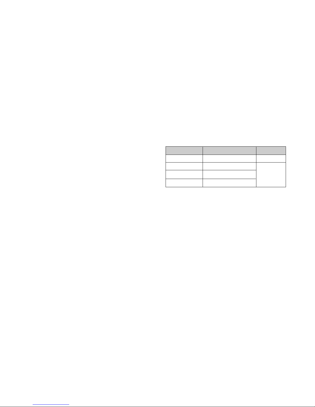
SPECIFICATIONS
MODE
NORMAL
STAND-BY
SUSPEND
OFF
POWER CONSUMPTION
less than 95 W
less than 15 W
less than 15 W
less than 3 W
LED COLOR
GREEN
AMBER
Page 3

SAFETY-RELATED COMPONENT WARNING!
There are special components used in this color monitor
which are important for safety. These parts are marked
on the schematic diagram and the replacement
parts list. It is essential that these critical parts should be
replaced with the manufacturer's specified parts to
prevent X-radiation, shock, fire, or other hazards. Do not
modify the original design without obtaining written
permission from GATEWAY or you will void the original
parts and labor guarantee.
CAUTION:
No modification of any circuit should be
attempted.
Service work should be performed only after
you are thoroughly familiar with all of the
following safety checks and servicing
guidelines.
SAFETY CHECK
Care should be taken while servicing this color monitor
because of the high voltage used in the deflection circuits.
These voltages are exposed in such areas as the
associated flyback and yoke circuits.
FIRE & SHOCK HAZARD
An isolation transformer must be inserted between the
color monitor and AC power line before servicing the
chassis.
• In servicing, attention must be paid to the original lead
dress specially in the high voltage circuit. If a short
circuit is found, replace all parts which have been
overheated as a result of the short circuit.
• All the protective devices must be reinstalled per the
original design.
• Soldering must be inspected for the cold solder joints,
frayed leads, damaged insulation, solder splashes, or
the sharp points. Be sure to remove all foreign
materials.
IMPLOSION PROTECTION
All used display tubes are equipped with an integral
implosion protection system, but care should be taken to
avoid damage and scratching during installation. Use only
same type display tubes.
X-RADIATION
The only potential source of X-radiation is the picture tube.
However, when the high voltage circuitry is operating
properly there is no possibility of an X-radiation problem.
The basic precaution which must be exercised is keep the
high voltage at the factory recommended level; the normal
high voltage is about 24.5kV. The following steps describe
how to measure the high voltage and how to prevent Xradiation.
Note : It is important to use an accurate high voltage
meter calibrated periodically.
• To measure the high voltage, use a high impedance
high voltage meter, connect (–) to chassis and (+) to
the CDT anode cap.
• Set the brightness control to maximum point at full
white pattern.
• Measure the high voltage. The high voltage meter
should be indicated at the factory recommended level.
• If the meter indication exceeds the maximum level,
immediate service is required to prevent the possibility
of premature component failure.
• To prevent X-radiation possibility, it is essential to use
the specified picture tube.
CAUTION:
Please use only a plastic screwdriver to protect yourself
from shock hazard during service operation.
SAFETY PRECAUTIONS
- 3 -
Page 4
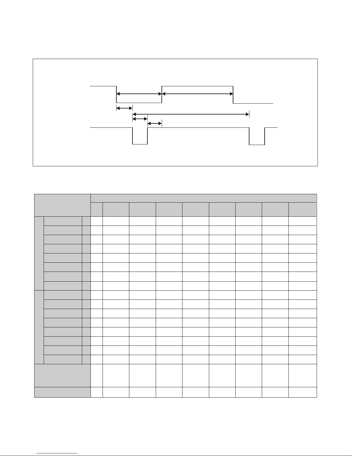
TIMING CHART
- 4 -
VIDEO
SYNC
C
E
D
F
AB
MODE
Resolution
Recall
H
O
R
I
Z
O
N
T
A
L
V
E
R
T
I
C
A
L
kHz
µs
µs
µs
µs
µs
µs
Hz
ms
ms
ms
ms
ms
ms
MODE 2
—
37.500
26.667
20.317
6.349
0.508
2.032
3.810
—
75.000
13.333
12.800
0.533
0.027
0.080
0.427
640
x
480
75Hz
Yes
MODE 1
—
31.469
31.778
25.422
6.356
0.636
3.813
1.907
—
59.940
16.683
15.253
1.430
0.318
0.064
1.048
640
x
480
60Hz
Yes
MODE 3
—
31.470
31.776
25.421
6.355
0.636
3.813
1.907
+
70.000
14.269
12.712
1.557
0.382
0.063
1.112
720
x
400
70Hz
Yes
MODE 4
+
37.879
26.400
20.000
6.400
1.000
3.200
2.200
+
60.317
16.579
15.840
0.739
0.026
0.106
0.607
800
x
600
60Hz
Yes
MODE 5
+
46.875
21.333
16.162
5.172
0.323
1.616
3.232
+
75.000
13.333
12.800
0.533
0.021
0.064
0.448
800
x
600
75Hz
Yes
MODE 6
—
48.363
20.677
15.754
4.923
0.369
2.092
2.462
—
60.004
16.666
15.880
0.786
0.062
0.124
0.600
1024
x
768
60Hz
Yes
MODE 7
+
60.023
16.660
13.003
3.657
0.203
1.219
2.235
+
75.029
13.328
12.795
0.533
0.017
0.050
0.466
1024
x
768
75Hz
Yes
MODE 8
+
63.981
15.630
11.852
3.778
0.444
1.037
2.296
+
60.020
16.661
16.005
0.656
0.016
0.047
0.594
1280
x
1024
60Hz
Yes
MARK
E
A
B
C
D
F
E
A
B
C
D
F
Sync Polarity
Frequency
Total Period
Video Active Time
Blanking Time
Front Porch
Sync Duration
Back Porch
Sync Polarity
Frequency
Total Period
Video Active Time
Blanking Time
Front Porch
Sync Duration
Back Porch
FACTORY PRESET MODE
* Mode 1~Mode 8: PRESET Mode
Page 5
Gateway
EV500
- 5 -
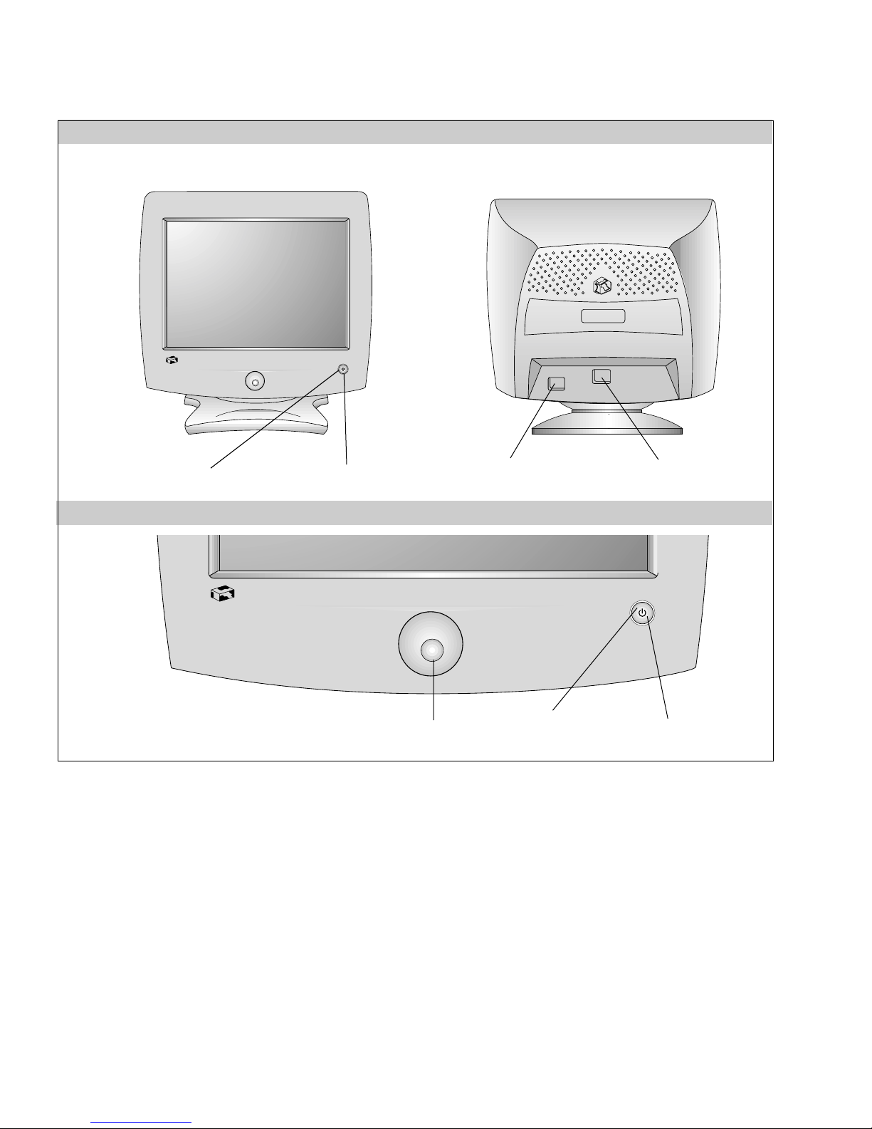
OPERATING INSTRUCTIONS
Gateway
EV500
FRONT VIEW REAR VIEW
AC Power Socket
Signal Cable
Power ON/OFF Button
Power (DPMS) Indicator
1. Power ON/OFF Button
This button is used to turn the monitor ON and OFF.
2. Power (DPMS) Indicator
This indicator lights up green when the monitor
operates normally; in DPMS (Energy Saving) mode,
– stand-by, suspend, or off mode – its color changes
to amber.
3. OSD Select/Adjustment
Use this knob for selecting (highlighting) an OSD
icon and adjusting level of the selected menu.
Front Control Panel
3. OSD Select/Adjustment
1. Power ON/OFF Button2. Power (DPMS) Indicator
Page 6
- 6 -
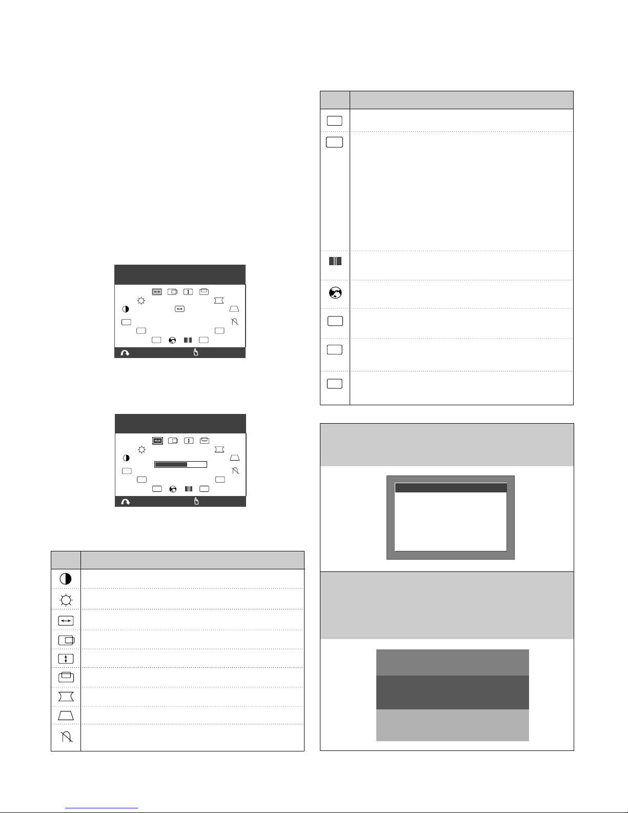
On Screen Display (OSD) Control
To adjust an image size, position, and operating
parameters are quick and easy with the On Screen Display
control system, using the OSD Select/Adjustment
knob.
A
quick example is given below to familiarize yourself with
use of the controls.
Example;
Note: (Monitor and PC’s power switch should be ON,
with an image or prompt on the screen). A single
press of the OSD Select/Adjustment knob will present
you the main menu as below:
To adjust this item, rotate the OSD Select/Adjustment
knob and push it at the point of the selected item.
The display will look like as below:
Listed below are icons, icon names.
Pincushion:
To correct bowing in or out of the image.
Tilt: To correct the image rotation.
Parallelogram: To correct the geometric distortion.
Pincushion Balance:
To correct balance on each side distortion.
Horizontal Moiré
Vertical Moiré
Trapezoid:
To correct the geometric distortion.
Degauss: Used to demagnetize the picture to give
a more accurate image and color.
Mode Recall: To recall factory preset mode.
R
Advanced Option: There are five kinds of options.
MORE
Color Select: To select color temperature or set
color level; 9300K / 6550K / USER.
Exit:
To make the OSD disappear on the screen.
Language Select:
To choose one of the five languages for the OSD menu.
EXIT
Information: There is information of video
modes-preset and user modes.
USER
OSD
OSD Manager: To adjust horizontal or vertical
position of the OSD image.
Icon Description
Horizontal Size: To adjust the image width.
Horizontal Position:
To move the image left or right.
Vertical Size : To adjust the image height.
Vertical Position: To move the image up or down.
Contrast: To adjust the image contrast level.
Brightness:
To adjust the screen brightness level.
Icon Description
Out of Frequency Range
When inputed video signal is not available, the message will
display as below:
Self Diagnosis
This monitor has a SELF DIAGNOSIS OSD feature that is
pops up when the signal cable is not connection between a
PC and a monitor. The message will be highlighted as
below.
OUT OF FREQUENCY
HF : 120.0kHz
VF : 110.0Hz
HF : 30-70kHz
VF : 50-160Hz
OPERATING FREQUENCY
:To reduce moiré.
Moiré is caused by intreference
the periodical display pattern
with the periodical dot screen.
H : 46.8 kHz V : 75 Hz
EXIT
800 x 600
HORIZONTAL
OSD
USER
:
NAVIGATE
SIZE
R
MORE
:
SELECT
H : 46.8 kHz V : 75 Hz
800 x 600
EXIT
OSD
USER
:
ADJUST
MORE
:
SELECT
R
MONITOR SELF TEST
YOUR MONITOR IS
WORKING CORRECTLY
CHECK COMPUTER POWER
AND MONITOR CABLE
Page 7
CONTROL LOCATIONS
- 7 -
MAIN
FBT
CONTROL
12
NO.1Ref. No.
SW201
NO.
2
Ref. No.
VR201
Control Function
POWER BUTTON
Control Function
OSD SELECT/ADJUSTMENT
Page 8
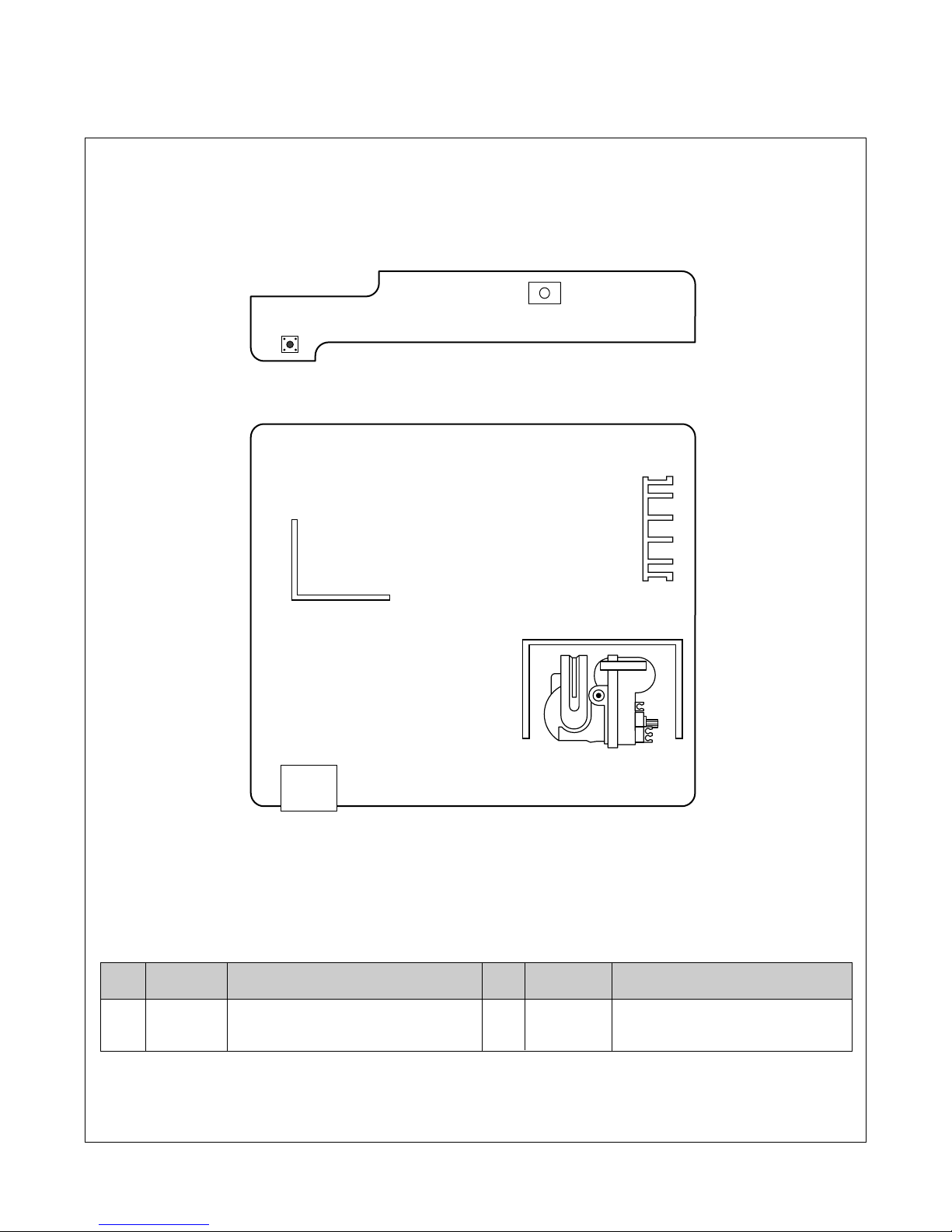
WIRING DIAGRAM
- 8 -
P201
P401
P501
W1
W3
P301
P302
P702
P402
P902
S
+
S
CDT
EARTH
P1
Signal
Cable
AC
Socket
FBT
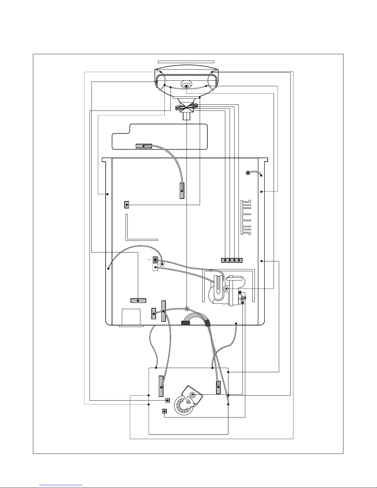
Page 9
DISASSEMBLY
- 9 -
2. BACK COVER REMOVAL
1) Remove two screw caps (a).
2) Remove four screws (b).
3) Slide the Back Cover away from the Front
Cabinet of the monitor.
(a)
1. TILT/SWIVEL REMOVAL
1) Set the monitor face downward.
2) Pressing the latch (a), carefully remove
the Tilt/Swivel by pulling it upward.
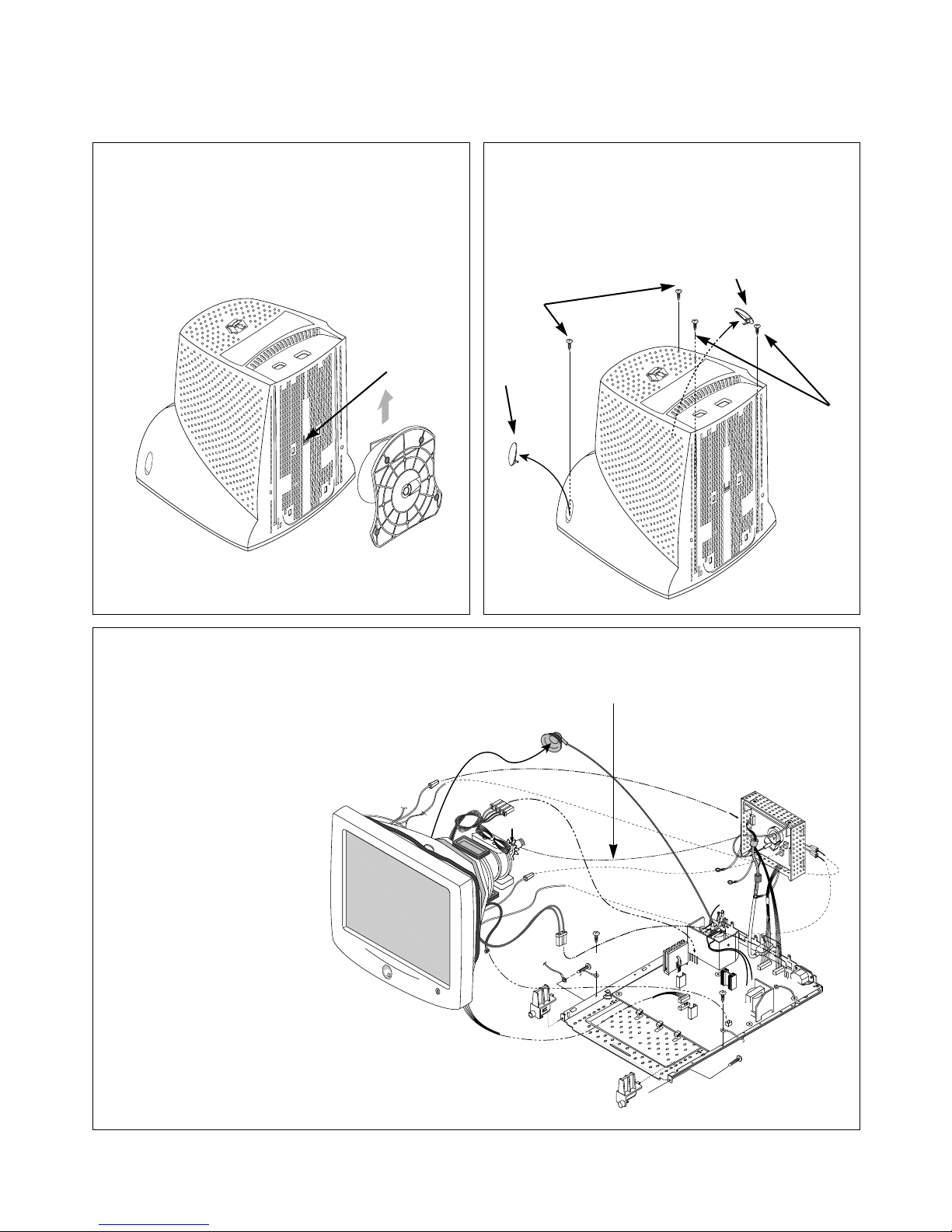
DY Pin
P201
Degaussing
Coil
DY Assembly Screw
P401
P501
P402
P701
P2
Tilt coil
Anode Cap
P902
3. TOTAL CHASSIS ASSEMBLY REMOVAL
1)
Remove connector (a) from the DY Assembly screw.
2) Disconnect P2(CDT EATH) and four pins (b)
from the Video PCB.
3) Carefully separate the CDT Board Assembly
from the CDT neck.
4) Discharge the remaining static electricity
by shorting between the Anode Cap
and the CDT ground.
5) Disconnect the Anode Cap
from the CDT.
6) Disconnect P902
(Degaussing pin),
P701(DY pin), and
P501 from the Main PCB.
7) Remove four screws (c).
8) Remove the Total Chassis
Assembly from the Cabinet.
(a)
(a)
(a)
(b)
(b)
(b)
(b)
(C)
(C)
(C)
(C)
Page 10
- 10 -
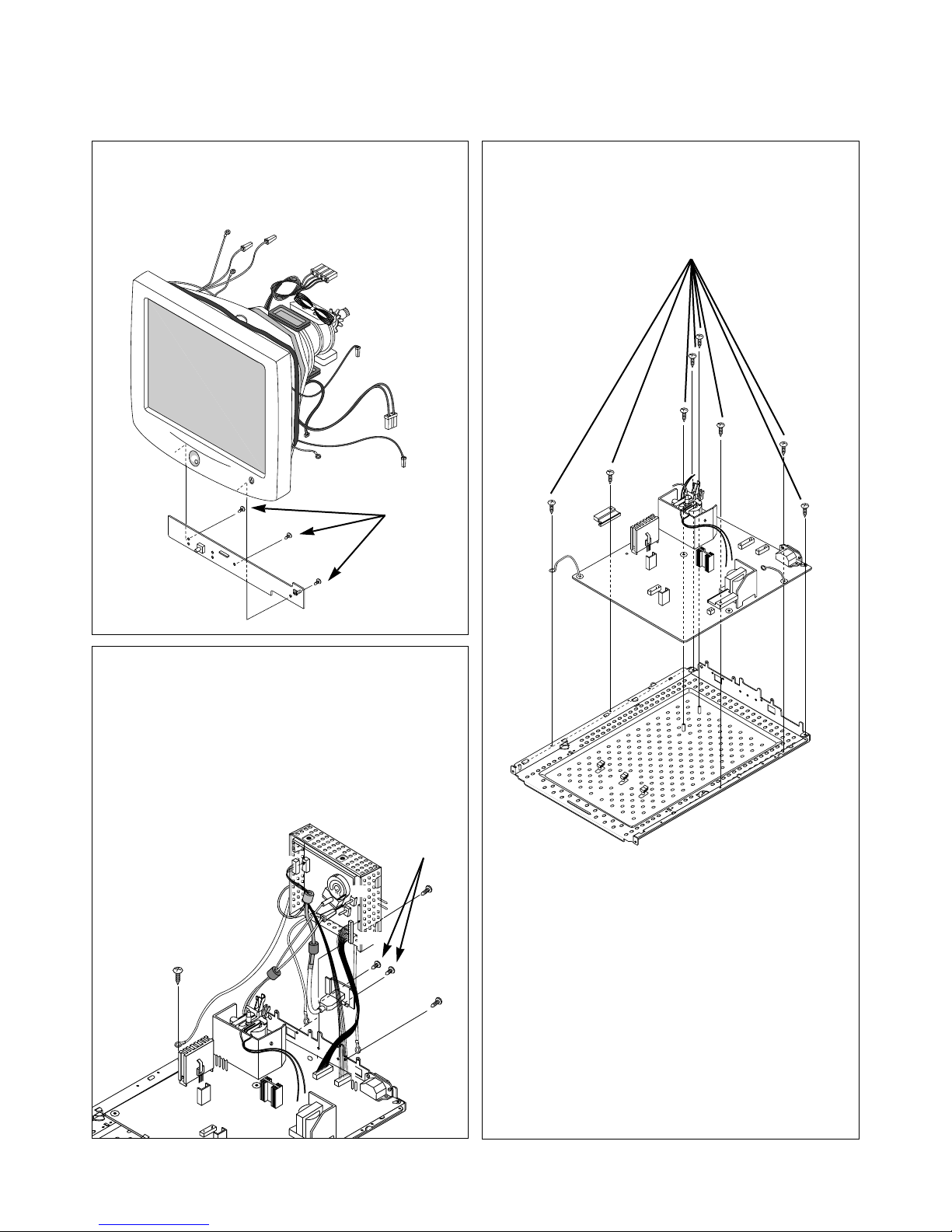
4. CONTROL PCB ASSEMBLY REMOVAL
1) Remove three screws (a).
2) Remove the Control PCB Assembly
from the Front Cabinet.
5. VIDEO PCB ASSEMBLY REMOVAL
1) Disconnect P301, P302, P1 from the Video
PCB.
2) Remove three screws (a).
3) Remove two screws (b).
3) Remove the Video PCB Assembly from the
Main total Ass’y
(a)
(a)
(a)
(b)
(a)
6. BOTTOM BRACKET REMOVAL
1) Remove eight screws (a).
2) Remove the Bottom Bracket.
(a)
P301
P1
P302
P702
Page 11
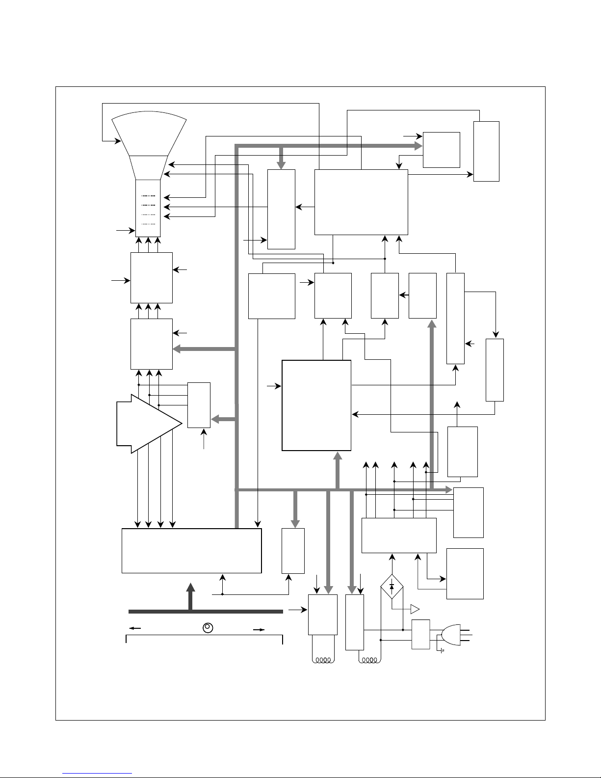
BLOCK DIAGRAM
- 11 -
AC 90~264V INPUT
Line
Filter
Degaussing
Circuit
SMPS
TRANS
(T901)
SMPS
CONTROL
(IC901)
DPM
CONTROL
CIRCUIT
5V
Regulator
105V
50V 15V
6.3V
-12V
TILT
Control
Circuit
6.3V
15V
E
2
PROM
(IC402)
5V
OSD IC
(IC301)
H-Sync Sig
V-Sync Sig
I
2
C DATA(SDA)
I
2
C CLOCK(SCL)
VIDEO
PRE-AMP
(IC302)
Signal
Cable
R
G
B
VIDEO
MAIN AMP
(IC303)
5V
5V
H/V Sync Processor
( IC701 )
TDA9113
V-OUT
( IC601)
TDA8172
H-OUT
( Q706)
H-Linearity
Correction
Screen Control
Circuit
DC/DC Converter
X-RAY
Protection
Circuit
FBT
( T701 )
Auto
Beam
Limit
Vertical Blanking,
Brightness Control
- 120V
40V
600V
15V
D/D Feed Back
15V
MICOM
(IC401)
SCL / SDA
H/V Sync,
PWM Control
12V
6.3V
15V
105V
15V
50V
DY CDT
Heater ( 6.3V )
I
2
C
I
2
C
I
2
C
H/V
Sync
G
1
Screen
Focus
H.V
R/G/B
Drive/Contrast
Cut-Off
H-DRV
B-DRV
B+
15V
TILT
COIL
DEGAUSSING
COIL
I
2
C
Vout
.CONTRAST
.BRIGHTNESS
.H-SIZE
.H-POSITION
.V-SIZE
.V-POSITION
.PINCUSHION
.TRAPEZOID
.DEGAUSS
.RECALL
.ADVANCED OPTION
.COLOR
.LANGUAGE
.INFORMATION
.OSD MANAGER
.EXIT
<OSD DISPLAY>
Page 12

DESCRIPTION OF BLOCK DIAGRAM
- 12 -
1. Line Filter & Associated Circuit.
This is used for suppressing noise of power input line
flowing into the monitor and/or some noise generated in
this monitor flowing out through the power input line.
That is to say, this circuit prevents interference between
the monitor and other electric appliances.
2. Degauss Circuit & Coil.
The degauss circuit consists of the degaussing coil, the
PTC(Positive Temperature Coefficient) thermistor(TH901),
and the relay(RL901). This circuit eliminates abnormal
color of the screen automatically by degaussing the
shadow mask in the CRT during turning on the power
switch. When you need to degauss in using the monitor,
select DEGAUSS on the OSD menu.
3. SMPS(Switching Mode Power Supply).
This circuit is working of 90~264V AC(50/60Hz).
The operation procedure is as follows:
1) AC input voltage is rectified and smoothed by the
bridge diodes (D901~D904) and the capacitor (C908).
2) The rectified voltage(DC) is applied to the primary
coil of the transformer(T901).
3) The control IC(IC901) generates switching pulse to
turn on and off the primary coil of the transformer
(T901) repeatedly.
4) Depending on turn ratio of the transformer, the
secondary voltages appear at the secondary coils of
the transformer(T901).
5) These secondary voltages are rectified by each
diode(D941, D951, D961, D971, D953) and operate
other circuit. (horizontal and vertical deflection, video
amplifier, ...etc.)
4. X-ray Protection.
I
f the high voltage of the FBT reaches up to 29kV (abnormal
state), Q807 operates and IC401(MICOM) pin 41 come to
low level. Then MICOM control IC701 (Deflection controller)
to stop Horizontal drive pulse and stop Horizontal Deflection.
5. Micom(Microprocessor) Circuit.
The operating procedure of Micom(Microprocessor) and its
associated circuit is as follows:
1) H and V sync signal is supplied from the signal cable.
2) The Micom(IC401) distinguishes polarity and
frequency of H and V sync.
3) The Micom sets operating mode and offers the
controlled data. (H-size, H-position, V-size, ... etc.)
4) The controlled data of each mode is stored in itself.
5) User can adjust screen condition by each OSD
function. The data of the adjusted condition is stored
in EEPROM(IC402).
6. Horizontal and Vertical Oscillation.
This circuit generates the horizontal pulse and the vertical
pulse by taking the H and V sync signal.
This circuit consists of the TDA9113(IC701) and the
associated circuit.
7. D/D(DC to DC) Converter.
This circuit supplies DC voltage to the horizontal deflection
output circuit by increasing DC 50V which is the
secondary voltage of the SMPS in accordance with the
input horizontal sync signal.
8. Side-Pincushion & Trapezoid Correction Cirucit.
This circuit improves the side-pincushion and the
trapezoid distortion of the screen by mixing parabola and
saw-tooth wave to output of the horizontal deflection D/D
converter which is used for the supply voltage(B+) of the
deflection circuit.
9. Horizontal Deflection Output Circuit.
This circuit makes the horizontal deflection by supplying
the saw-tooth current to the horizontal deflection yoke.
10. High Voltage Output & FBT(Flyback Transformer).
The high voltage output circuit is used for generating pulse
to the primary coil of the FBT(Flyback Transformer
(T701)). A boosted voltage(about 24.5kV) appears at the
secondary of the FBT and it is supplied to the anode,
focus, and screen voltage of the CRT.
11. H-Linearity Correction Circuit.
This circuit corrects the horizontal linearity for each
horizontal sync frequency.
12. Vertical Output Circuit.
This circuit takes the vertical ramp wave from the
TDA9113(IC701) and performs the vertical deflection by
supplying the saw-tooth current to the vertical deflection
yoke.
13. H& V Blanking and Brightness Control.
Blanking circuit eliminates retrace line by supplying
negative pulse to the G1 of the CRT. And Brightness
circuit is used for control of the screen brightness by
changing DC level of the G1.
14. Image Rotation (Tilt) Circuit.
This circuit corrects the tilt of the screen by supplying the
image rotation signal to the tilt coil which is attached near
the deflection yoke of the CRT.
Page 13

- 13 -
15. Video Pre-Amp Circuit.
This circuit amplifies the analog video signal from 0-0.7V
to 0-4V. It is operated by taking the clamp, R, G, B drive
and contrast signal from the Micom(IC401).
16. Video Output Amp Circuit.
This circuit amplifies the video signal which comes from
the video pre-amp circuit and amplified it to applied the
CRT cathode.
Page 14

ADJUSTMENT
- 14 -
GENERAL INFORMATION
All adjustment are thoroughly checked and corrected
when the monitor leaves the factory, but sometimes
several adjustments may be required.
Adjustment should be following procedure and after
warming up for a minimum of 30 minutes.
• Alignment appliances and tools.
- IBM compatible PC.
- Programmable Signal Generator.
(eg. VG-819 made by Astrodesign Co.)
- EPROM or EEPROM with saved each mode data.
- Alignment Adaptor and Software.
- Digital Voltmeter.
- White Balance Meter.
- Luminance Meter.
- High-voltage Meter.
AUTOMATIC AND MANUAL DEGAUSSING
The degaussing coil is mounted around the CDT so that
automatic degaussing when turn on the monitor. But a
monitor is moved or faced in a different direction, become
poor color purity cause of CDT magnetized, then
press
DEGAUSS on the OSD menu.
ADJUSTMENT PROCEDURE & METHOD
-Install the cable for adjustment such as Figure 1and run
the alignment program on the DOS for IBM compatible PC.
-Set external Brightness and Contrast volume to max position.
1. Adjustment for B+ Voltage.
1) Display cross hatch pattern at Mode 7.
2) Adjust voltage to 51V
±
0.5Vdc with VR901.
2. Adjustment for High-Voltage.
1) Display cross hatch pattern at Mode 7.
2) Adjust Hight Voltage to 24.5V
±
0.1 kVdc.
3. Adjustment for Factory Mode (Preset Mode).
1) Display cross hatch pattern at Mode 1~8.
2) Run alignment program for CG572E on the
IBM compatible PC.
3) EEPROM→ ALL CLEAR→ Y(Yes) command.
4) COMMAND → PRE START → Y(Yes) command.
5) DIST. ADJ. → CTRL PWM → TILT command.
6) Adjust tilt as arrow keys to be the best condition.
7) DIST. ADJ. → BALANCE command.
8) Adjust balance of side-pincushion as arrow keys to
be the best condition.
9) DIST. ADJ. → BALANCE command.
10)
Adjust parallelogram as arrow keys to be the best
condition.
11)
DIST. ADJ. → FOS. ADJ. command.
12)
Adjust V-SIZE as arrow keys to 200±1mm.
13)
Adjust V-POSITION as arrow keys to be the best
condition.
14)
Adjust H-SIZE as arrow keys to 270±1mm.
15)
Adjust H-POSITION as arrow keys to be the best
condition.
16)
Adjust S-PCC (Side-Pincushion) as arrow keys to be
the best condition.
17)
Adjust TRAPEZOID as arrow keys to be the best
condition.
18)
Display from Mode 1 to Mode 8 and repeat above
from number
12)
to
17)
.
19)
PRESET EXIT → Y (Yes) command.
4. Adjustment for White Balance and Luminance.
1) Set the White Balance Meter.
2) Press the DEGAUSS on the OSD menu for
demagnetization of the CDT.
3) COLOR ADJ. → LUMINANCE command of the
alignment program.
4) Set Brightness and Contrast to Max and ABL to
200(C8) (decimal) position.
5) Display color 0,0 pattern at Mode 3.
6) COLOR ADJ. → BIAS ADJ. command of the
alignment program.
7) Check whether green color or not at R-BIAS and BBIAS to 50 position and G-BIAS to 127(7F) to
position. Set Sub-Brightness to 80(Decimal).
Adjust
G2(Screen) volume to 0.50
±
0.05FL of the raster
luminance.Check it's not green color.
8) Adjust R-BIAS and B-BIAS command to x=0.283
±
0.005 and y=0.298±0.005 on the White Balance
Meter with PC arrow keys.
9)
Adjust SUB-Brightness command to 0.7±0.05FL of
the raster luminance.
10)
PRESET EXIT → Y (Yes) command.
11)
Display color 15,0 full Window pattern (70x70mm) at
Mode 3.
12)
DRIVE ADJ. command.
13)
Set SUB-CONTRAST to 100 position.
14)
Set G-DRIVE to 160 (decimal) at DRIVE of the alignment
program.
15)
Adjust R-DRIVE and B-DRIVE command to white
balance x=0.283
±
0.003 and y=0.298±0.003 on the
White Balance Meter with PC arrow keys.
16)
Adjust SUB-CONTRAST command to 54±0.5FL of
the raster luminance.
Page 15

- 15 -
Figure 1. Cable Connection
17)
PRESET EXIT → Y (Yes) command.
18)
Display color 15,0 full white patten at Mode 3.
19)
COLOR ADJ. → LUMINANCE → ABL command.
20)
Adjust ABL to 40±0.5FL of the luminance.
21)
PRESET EXIT → Y (Yes) command.
22)
Exit from the program.
5. Adjustment for Focus.
1) Set the Brightness and Contrast to max position.
2) Display H character in full screen at Mode 7.
3) Adjust Focus control on the FBT that focus should
be the best condition.
220
Monitor to be
adjusted
Video
Signal
Generator
IBM
Compatible PC
Parallel Port
Power inlet (required)
Power LED
ST Switch
Power Select Switch
(110V/220V)
Control Line
Not used
RS232C
PARALLEL
V-SYNC
POWER
ST
VGS
MONITOR
E
E
V-Sync On/Off Switch
(Switch must be ON.)
F
F
A
A
B
B
C
C
15
10
5
5
69
1
1
1
14
13
25
6
5V
5V
5V
4.7K
4.7K
4.7K
74LS06
74LS06
OFF ON
OFF
ON
11
Page 16

TROUBLESHOOTING GUIDE
- 16 -
NO POWER
(POWER INDICATOR OFF)
TROUBLE IN
D901, D902, D903, D904
TROUBLE IN FUSE
(F901)
TROUBLE IN
IC901
TROUBLE IN
D941, D951, D961,
D971, D953
TROUBLE IN
IC950, Q972, Q971, Q952,
Q951, Q942, Q941, IC702
CHECK
FUSE OK?
CHECK
C908 VOLTAGE?
(AC120V: 160VDC,
AC220V: 304VDC)
NO
YES
YES
YES
YES
NO
NO
NO
CHECK
IC901 PIN 6
WAVEFORM
(SQUARE WAVE
COMES OUT?)
CHECK
D941, D951, D961,
D971, D953,
VOLTAGE?
1. NO POWER
Page 17

- 17 -
2. NO CHARACTER
NO CHARACTER
CHECK
IC302
PIN 17(6.3V) ?
CHECK
IC302 PIN 1, 3, 5?
CHECK
IC302 PIN 14, 16, 18 ?
CHECK
IC303
PIN 1, 5, 11 ?
CHECK
IC303 PIN 4 (105V)
PIN 8 (15V) ?
TROUBLE IN
P302 6.3V LINE
TROUBLE IN
PC SIGNAL,
P301 SIGNAL CABLE
TROUBLE IN
IC302
TROUBLE IN
P302 15V LINE/
105V LINE
TROUBLE IN IC303
NO
YES
NO
NO
YES
YES
YES
YES
NO
NO
CHECK
R, G, B CATHODE
VOLTAGE?
TROUBLE IN
R341~R343,
R351~R353, L301~L303,
D307~D312
TROUBLE IN
CRT SOCKET
YES
NO
Page 18

- 18 -
NO VIDEO
(POWER INDICATOR ON)
CHECK
POWER INDICATOR
GREEN or AMBER?
CHECK
D712 ANODE
(-120V)?
CHECK
G1VOLTAGE?
(
-35~-15V)
TROUBLE IN
D712
TROUBLE IN
Q704
DPM MODE
(NO H and/or V SYNC)
AMBER
NO
GREEN
YES
NO
3. NO RASTER
CHECK
CDT HEAT
VOLTAGE? (6.3V)
TROUBLE IN
D941, Q942, Q941
YES
NO
TROUBLE IN
CDT
YES
Page 19

- 19 -
4. NO HORIZONTAL DEFLECTION
NO H-DEFLECTION
(ONE VERTICAL LINE)
CHECK
Q706?
CHECK
B+ VOLTAGE
(50V)?
CHECK
T701(FBT) PIN 2
(31KHZ 70V,
69KHZ 143V) ?
CHECK
Q705 COLLECTOR
WAVEFORM?
TROUBLE IN
Q706
TROUBLE IN
50V LINE
TROUBLE IN
Q719, Q720, Q717, D710
TROUBLE IN
Q705
TROUBLE IN
T701, P701
NO
NO
YES
YES
YES
YES
NO
NO
Page 20

- 20 -
5. TROUBLE IN H-LINEARITY
UNBALANCED OF H-LIN.
CHECK
IC401
PIN 22, 23, 24 ?
CHECK
Q711~Q716?
CHECK
L703?
TROUBLE IN
IC401 (MICOM)
TROUBLE IN
Q711 ~ Q716
TROUBLE IN
L703
TROUBLE IN
C722, C723, C726, C729
NO
NO
NO
YES
YES
YES
Cs SIGNAL TABLE
HORIZONTAK
FREQUENCY(fH)
29K ~ 35.9K
36K ~ 38.9K
39K ~ 48.9K
49K ~ 64.9K
65K ~ 71K
Cs1
L
L
H
L
H
Cs3
L
L
H
H
H
Cs2
L
H
L
H
H
Page 21

- 21 -
6. NO VERTICAL DEFLECTION
NO V-DEFLECTION
(ONE HORIZONTAL LINE)
CHECK
IC601 PIN 3
(15V)?
CHECK
IC601 PIN 4
(-12V)?
CHECK
IC701 PIN 23?
TROUBLE IN
D602 15V LINE
TROUBLE IN
-12V LINE
D953, C605, C606, C962
TROUBLE IN
IC701
TROUBLE IN
IC601, V-CIRCUIT
NO
NO
YES
YES
YES
NO
3V
Page 22

- 22 -
TROUBLE IN
OSD PERIPHERAL
CIRCUIT
NO OSD
TROUBLE IN
5V LINE
TROUBLE IN
IC601 PIN8 (V-FBP),
T701 40V LINE (H-FBP)
TROUBLE IN
IC302, IC301
TROUBLE IN
IC301, IC302
NO
YES
DC 5V
YES
YES
YES
NO
NO
NO
Pin 5
5V
5V
Pin 10
5V
H+V
5V
CHECK
IC301 B
+
?
CHECK
IC301 PIN 12
WAVEFORM ?
(ENTER BUTTON MUST BE PRESSED.)
7. TROUBLE IN OSD
CHECK
IC301 PIN 5, 10
WAVEFORM?
CHECK
IC301 PIN 13, 14, 15 ?
negative pulse
negative pulse
Page 23

- 23 -
CHECK
IC401 (MICOM)
PIN 1, 42 (H/V INPUT)
SIGNAL?
CHECK
IC401 PIN 6
WAVEFORM?
CHECK
IC401 (MICOM)
PIN 3, 4 ?
CHECK
B+LINE
(6.3V,15V, 105V) ?
CHECK PC,
(PC IS NOT GOING INTO
DPM OFF MODE)
TROUBLE IN
X401
TROUBLE IN
IC401 (MICOM)
TROUBLE IN
Q941, Q942, Q951, Q952,
Q971, Q972
TROUBLE IN PC
OFF MODE FAILURE
INPUT H/V SYNC SIGNAL
H/V SYNC
(NO OFF MODE.)
NO
NO
NO
NO (DPMF: 0V)
DPM TABLE
Mode
Item
NORMAL
STAND-BY
SUSPEND
OFF
DPMF
H
H
H
L
LED
GREEN
AMBER
AMBER
AMBER
DPMS
H
L
L
L
YES
YES
SEE DPM TABLE
YES
YES
5V
24MHz
8. TROUBLE IN DPM
Page 24

- 24 -
CHECK
IC401 PIN 31
(0V)?
CHECK
Q953 COLLECTOR
VOLTAGE?
CHECK
P902 ?
CHECK
RL901?
TROUBLE IN
IC401 (MICOM)
TROUBLE IN
Q953
TROUBLE IN
P902
TROUBLE IN
RL901
TROUBLE IN
TH901,
DEGAUSSING COIL
NO DEGAUSSING
DC 15V
NO
NO
NO
NO
YES
YES
YES
YES
(DEGAUSS ON THE OSD MENU MUST BE PRESSED.)
9. NO DEGAUSSING
Page 25

- 25 -
10. NO TILT (NO ROTATION)
NO TILT (NO ROTATION)
TROUBLE IN
IC401 (
MICOM)
TROUBLE IN
15V LINE, 6.3V LINE
TROUBLE IN
Q501~Q503
TROUBLE IN
P501, TILT COIL, D501
NO
YES
YES
YES
CHECK
15V LINE
AND 6.3V LINE ?
CHECK
Q503 EMITTER
VOLTAGE ?
NO
NO
CHECK
Q504(COLLECTOR)
WAVE FORM ?
12V
Page 26

1
2
4
5
6
B
C
A
8
7
3
10
10
12
11
11-1
17
14
16
13
15
9
Ref. No.
1
2
3
4
5
6
7
8
9
10
11
11-1
12
13
14
15
16
17
A
B
C
Material
*Remark
Description
CABINET ASS'Y, KCG572E G/WAY 028
CDT, M36LBL803X00NLLW
SCREW ASS’Y, PHP+5x30BP+GW18
COIL, DEGAUSSING 870MM 8.4 OHM
FBT, FMMTC81-M1035A
SOCKET(CIRC), POWER BCP-03A
PWB(PCB), CG572C CONTROL REV1.0
BRACKET CG572C SUPPORTER(R)
BRACKET CG572C SUPPORTER(L)
SCREW, PTP4x20BP(MSWR, FZMY)
SIGNAL CABLE(IN), UL 2990-9C AT
SIGNAL CABLE(OUT), UL 2990-9C DT
METAL SHIELD BOTTOM, CG572C
COVER SCREW(R)
COVER SCREW(L)
SCREW, PTP4x20BP(MSWR, FZMY)
BACK COVER ASS’Y, CG572C 3808
TILT SWIVEL ASS’Y, KCG572E B041/T047
PWB(PCB) ASS'Y, VIDEO KCG572E XGWND
PWB(PCB) ASS'Y, MAIN KCG572E XGWND
MAIN TOTAL ASS’Y, KCG572E G/WAY
Part No.
3091TKB033B
2423GB0A81Z
339-002D
150-A29A
6174Z-1035A
6620TKB002A
6871TST193B
4810TKK145A
4810TKK146A
332-102F
6866TA9020B
387-874F
4950TKK259A
3550TKK149A
3550TKK150A
332-102F
3809TKB018A
3043TKK066B
6871TVT193B
6871TMT191B
3313T15065B
Q'ty
1
1
4
1
1
1
1
1
1
2
1
1
1
1
1
4
1
1
1
1
1
EXPLODED VIEW PARTS LISTEXPLODED VIEW
Page 27

REPLACEMENT PARTS LIST
CAUTION: BEFORE REPLACING ANY OF THESE COMPONENTS,
READ CAREFULLY THE SAFETY PRECAUTIONS IN THIS MANUAL.
* NOTE : S SAFETY Mark
AL ALTERNATIVE PARTS
MODEL:
EV500
DATE: 2000. 9. 16.
*S *AL LOC. NO. PART NO. DESCRIPTION / SPECIFICATION REMARK
C201 0CN1040K949 CAPACITOR, TUBULAR(HIGH DIELEC), 0.1M 50V Z F TA52
C202 0CN1040K949 CAPACITOR, TUBULAR(HIGH DIELEC), 0.1M 50V Z F TA52
C203 0CN1040K949 CAPACITOR, TUBULAR(HIGH DIELEC), 0.1M 50V Z F TA52
C204 0CE106BK638 CAPACITOR, AL.ELECTROLYTIC 10U KME 50V M FM5 TP5
C210 0CN1040K949 CAPACITOR, TUBULAR(HIGH DIELEC), 0.1M 50V Z F TA52
C211 0CN1040K949 CAPACITOR, TUBULAR(HIGH DIELEC), 0.1M 50V Z F TA52
C301 181-288B CAPACITOR, POLYESTER, MKT 100V 104JTR PHS26104
C302 181-288B CAPACITOR, POLYESTER, MKT 100V 104JTR PHS26104
C303 181-288B CAPACITOR, POLYESTER, MKT 100V 104JTR PHS26104
C304 181-288B CAPACITOR, POLYESTER, MKT 100V 104JTR PHS26104
C305 181-288K CAPACITOR, POLYESTER, MKT 100V 683JTR PHS26683
C306 0CE107CF638 CAPACITOR, AL.ELECTROLYTIC, 100UF SHL,SD 16V M FM5 TP 5
C307 0CK1040K945 CAPACITOR, CERAMIC (HIGH DIELECTRIC), 0.1UF 50V Z F TR
C308 0CK1040K945 CAPACITOR, CERAMIC (HIGH DIELECTRIC), 0.1UF 50V Z F TR
C309 0CE476CF638 CAPACITOR, AL.ELECTROLYTIC, 47UF SHL,SD 16V M FM5 TP 5
C311 0CC2210K415 CAPACITOR, CERAMIC (TEMP. COMPENSATE), 220P 50V J NPO TP
C312 0CE476CF638 CAPACITOR, AL.ELECTROLYTIC, 47UF SHL,SD 16V M FM5 TP 5
C314 0CK1010K515 CAPACITOR, CERAMIC (HIGH DIELECTRIC), 100PF 50V K B TR
C320 0CK1040K945 CAPACITOR, CERAMIC (HIGH DIELECTRIC), 0.1UF 50V Z F TR
C321 0CE108CH630 CAPACITOR, AL.ELECTROLYTIC, 1000UF SHL 25V M FM5 BULK
C322 0CK1040K945 CAPACITOR, CERAMIC (HIGH DIELECTRIC), 0.1UF 50V Z F TR
C325 0CK1040K945 CAPACITOR, CERAMIC (HIGH DIELECTRIC), 0.1UF 50V Z F TR
C326 0CK2220W515 CAPACITOR, CERAMIC (HIGH DIELECTRIC), 2200P 500V K B TS
C327 0CK10302940 CAPACITOR, CERAMIC (HIGH DIELECTRIC), 0.01M 2KV Z F S
C328 0CK10201515 CAPACITOR, CERAMIC (HIGH DIELECTRIC), 1000P 1KV K B TS
C330 0CK1010K515 CAPACITOR, CERAMIC (HIGH DIELECTRIC), 100PF 50V K B TR
C331 0CC4700W405 CAPACITOR, CERAMIC (TEMP. COMPENSATE), 47PF 500V J SL TP
C332 0CK10301945 CAPACITOR, CERAMIC (HIGH DIELECTRIC), 10000PF D 1KV Z F(Y5V) TR
C346 0CK10301945 CAPACITOR, CERAMIC (HIGH DIELECTRIC), 10000PF D 1KV Z F(Y5V) TR
C380 0CE107CF638 CAPACITOR, AL.ELECTROLYTIC, 100UF SHL,SD 16V M FM5 TP 5
C383 0CE335CK638 CAPACITOR, AL.ELECTROLYTIC, 3.3UF SHL,SD 50V M FM5 TP 5
C384 0CZZTFT001F CAPACITOR, ECQB1H332JM3 332J 50V TP5.0 MATSUSHITA
C385 0CK4710K515 CAPACITOR, CERAMIC (HIGH DIELECTRIC), 470PF 50V K B TR
C386 0CZZTFT001F CAPACITOR, ECQB1H332JM3 332J 50V TP5.0 MATSUSHITA
C388 0CZZTFT001F CAPACITOR, ECQB1H332JM3 332J 50V TP5.0 MATSUSHITA
C389 0CE107CP618 CAPACITOR, AL.ELECTROLYTIC, 100U SHL 160V M FL TP5
C391 0CE225EP638 CAPACITOR, FIXED ELECTROLYTIC, 2.2UF KMG 160V 20% TP 5 FM5
C401 0CK1040K945 CAPACITOR, CERAMIC (HIGH DIELECTRIC), 0.1UF 50V Z F TR
C402 0CC1200K415 CAPACITOR, CERAMIC (TEMP. COMPENSATE), 12P 50V J NP0 TS
C403 0CC1200K415 CAPACITOR, CERAMIC (TEMP. COMPENSATE), 12P 50V J NP0 TS
C404 0CN2210K519 CAPACITOR, TUBULAR(HIGH DIELEC), 220P 50V K B TA52
C405 0CK1010K515 CAPACITOR, CERAMIC (HIGH DIELECTRIC), 100PF 50V K B TR
C406 0CN3310K519 CAPACITOR, TUBULAR(HIGH DIELEC), 330P 50V K B TA52
C407 0CK1040K945 CAPACITOR, CERAMIC (HIGH DIELECTRIC), 0.1UF 50V Z F TR
C408 0CK1010K515 CAPACITOR, CERAMIC (HIGH DIELECTRIC), 100PF 50V K B TR
C409 0CN1040K949 CAPACITOR, TUBULAR(HIGH DIELEC), 0.1M 50V Z F TA52
C413 0CN3310K519 CAPACITOR, TUBULAR(HIGH DIELEC), 330P 50V K B TA52
C414 0CE104CK638 CAPACITOR, AL.ELECTROLYTIC, 0.1UF SHL,SD 50V M FM5 TP 5
C415 0CE106CF638 CAPACITOR, AL.ELECTROLYTIC, 10UF SHL,SD 16V M FM5 TP 5
C416 0CE105CK638 CAPACITOR, AL.ELECTROLYTIC, 1UF SHL,SD 50V M FM5 TP 5
C417 0CK1040K945 CAPACITOR, CERAMIC (HIGH DIELECTRIC), 0.1UF 50V Z F TR
C501 0CK1040K945 CAPACITOR, CERAMIC (HIGH DIELECTRIC), 0.1UF 50V Z F TR
C502 0CE106CF638 CAPACITOR, AL.ELECTROLYTIC, 10UF SHL,SD 16V M FM5 TP 5
C601 0CE477CH618 CAPACITOR, AL.ELECTROLYTIC, 470UF SHL 25V M FL TP5
C602 0CE227CK618 CAPACITOR, AL.ELECTROLYTIC, 220U SHL 50V M FL TP5
C603 0CQ3921N419 CAPACITOR, POLYESTER, 0.0039UF D 100V J PE NI TP
C605 0CE108CH630 CAPACITOR, AL.ELECTROLYTIC, 1000UF SHL 25V M FM5 BULK
C606 0CN1040K949 CAPACITOR, TUBULAR(HIGH DIELEC), 0.1M 50V Z F TA52
C607 0CE105CK638 CAPACITOR, AL.ELECTROLYTIC, 1UF SHL,SD 50V M FM5 TP 5
C608 0CN2220K519 CAPACITOR, TUBULAR(HIGH DIELEC), 2200PF 50V K B TA52
- 28 -
CAPACITORs
Page 28

MODEL:
EV500
DATE: 2000. 9. 16.
*S *AL LOC. NO. PART NO. DESCRIPTION / SPECIFICATION REMARK
C609 181-288B CAPACITOR, POLYESTER, MKT 100V 104JTR PHS26104
C610 181-288Q CAPACITOR, POLYESTER, MKT 100V 154JTR PHS26154
C701 181-288B CAPACITOR, POLYESTER, MKT 100V 104JTR PHS26104
C702 181-288N CAPACITOR, POLYESTER, MKT 100V 103JTR PHS86103
C703 0CK8210K515 CAPACITOR, CERAMIC (HIGH DIELECTRIC), 820P 50V K B TS
C704 181-288N CAPACITOR, POLYESTER, MKT 100V 103JTR PHS86103
C705 0CE475CK638 CAPACITOR, AL.ELECTROLYTIC, 4.7UF SHL,SD 50V M FM5 TP 5
C706 0CE2256K618 CAPACITOR, AL.ELECTROLYTIC, 2.2U SMS 50V M FM5 TP5
C708 0CK2210K515 CAPACITOR, CERAMIC (HIGH DIELECTRIC), 220P 50V K B TS
C709 0CK1020K515 CAPACITOR, CERAMIC (HIGH DIELECTRIC), 1000PF 50V K B TR
C710 181-288Q CAPACITOR, POLYESTER, MKT 100V 154JTR PHS26154
C711 181-288E CAPACITOR, POLYESTER, MKT 100V 474JTR PHS 26474
C712 181-288P CAPACITOR, POLYESTER, MKT 100V 153JTR PHS86153
C713 0CK2210K515 CAPACITOR, CERAMIC (HIGH DIELECTRIC), 220P 50V K B TS
C714 0CE337CH638 CAPACITOR, AL.ELECTROLYTIC, 330UF SHL 25V M FM5 TP5
C715 0CZZTFT001M CAPACITOR, ECQB1H103JM3 103J 50V TP5.0 MATSUSHITA
C716 181-288C CAPACITOR, POLYESTER, MKT 100V 224JTR PHS 26224
C717 0CE476CF638 CAPACITOR, AL.ELECTROLYTIC, 47UF SHL,SD 16V M FM5 TP 5
C718 0CN1040K949 CAPACITOR, TUBULAR(HIGH DIELEC), 0.1M 50V Z F TA52
C719 0CZZTAB001A CAPACITOR, SM-BP(P)/BP 10UF 50V 13*25 BK5
C720 0CK5610W515 CAPACITOR, CERAMIC (HIGH DIELECTRIC), 560P 500V K B TS
C721 0CE227CH638 CAPACITOR, AL.ELECTROLYTIC, 220UF SHL,SD 25V M FM5 TP 5
C722 181-303F CAPACITOR, POLYPROPYLENE, 274J 30.0*21.0*13.5*20.0 250V J PU FM20
C723 181-305J CAPACITOR, POLYPROPYLENE, 474J 26.0*17.0*10.5*15.0 250V J MPP FM15
C724 0CK1040K945 CAPACITOR, CERAMIC (HIGH DIELECTRIC), 0.1UF 50V Z F TR
C725 0CQ1041N409 CAPACITOR, POLYESTER, 0.1000UF 100V J PE TP
C726 181-305G CAPACITOR, POLYESTER, MPP 250V 334J S=10.0
C727 0CK1040K945 CAPACITOR, CERAMIC (HIGH DIELECTRIC), 0.1UF 50V Z F TR
C728 0CQ5621N419 CAPACITOR, POLYESTER, 5600P 100V J POLY NI TP
C729 181-305A CAPACITOR, POLYESTER, MPP 250V 104J S=10.0
C730 0CK1040K945 CAPACITOR, CERAMIC (HIGH DIELECTRIC), 0.1UF 50V Z F TR
C731 181-292F CAPACITOR, POLYPROPYLENE, 512H 31.0*16.5*9.5*20.0 1.6KV J BUP FM20
C732 0CQ1031N419 CAPACITOR, POLYESTER, 0.01U 100V J POLY NI TP
C733 0CBZTBU003K CAPACITOR, POLYPROPYLENE, 472J 20.0*13.0*8.0*10.0 800V J BUP FM10
C734 181-288B CAPACITOR, POLYESTER, MKT 100V 104JTR PHS26104
C735 181-288P CAPACITOR, POLYESTER, MKT 100V 153JTR PHS86153
C736 0CE105CP638 CAPACITOR, AL.ELECTROLYTIC, 1UF SHL,SD 160V M FM5 TP 5
C738 0CE105CK638 CAPACITOR, AL.ELECTROLYTIC, 1UF SHL,SD 50V M FM5 TP 5
C739 0CE476CN618 CAPACITOR, AL.ELECTROLYTIC, 47UF SHL 100V M FL TP5
C740 0CE227CL630 CAPACITOR, AL.ELECTROLYTIC, 220U SHL 63V M FM5
C741 0CZZTFT002B CAPACITOR, ECQV1H154JZ3 154J 50V TP5.0 MATSUSHITA
C742 0CK1520K515 CAPACITOR, CERAMIC (HIGH DIELECTRIC), 1500P 50V K B TS
C743 0CK3310W515 CAPACITOR, CERAMIC (HIGH DIELECTRIC), 330P 500V K B TS
C744 0CE476CQ630 CAPACITOR, AL.ELECTROLYTIC, 47UF SHL 200V M FM5 BULK
C745 0CE106CK638 CAPACITOR, AL.ELECTROLYTIC, 10UF SHL,SD 50V M FM5 TP 5
C746 0CK33101515 CAPACITOR, CERAMIC (HIGH DIELECTRIC), 330P 1KV K B TS
C747 0CN2210K519 CAPACITOR, TUBULAR(HIGH DIELEC), 220P 50V K B TA52
C748 0CZZTFT001Z CAPACITOR, ECQB1H104JM3 104J 50V TP5.0 MATSUSHITA
C749 0CE476CP630 CAPACITOR, AL.ELECTROLYTIC, 47UF SHL 160V M FM5 BULK
C750 181-288B CAPACITOR, POLYESTER, MKT 100V 104JTR PHS26104
C751 181-288B CAPACITOR, POLYESTER, MKT 100V 104JTR PHS26104
C752 0CE476CF638 CAPACITOR, AL.ELECTROLYTIC, 47UF SHL,SD 16V M FM5 TP 5
C753 0CN2210K519 CAPACITOR, TUBULAR(HIGH DIELEC), 220P 50V K B TA52
C754 0CC4700W405 CAPACITOR, CERAMIC (TEMP. COMPENSATE), 47PF 500V J SL TP
C790 0CE106CF638 CAPACITOR, AL.ELECTROLYTIC, 10UF SHL,SD 16V M FM5 TP 5
C805 0CE106CK638 CAPACITOR, AL.ELECTROLYTIC, 10UF SHL,SD 50V M FM5 TP 5
C901 0CBZTBU002B CAPACITOR, POLYESTER, BULK PCX2 335 474K
C902 0CBZTBU002A CAPACITOR, POLYESTER, BULK PCX2 335 224K
C903 0CKZTTA003D CAPACITOR, CERAMIC (HIGH DIELECTRIC), SC SAMWHA 250V 1000F
C904 0CKZTTA003D CAPACITOR, CERAMIC (HIGH DIELECTRIC), SC SAMWHA 250V 1000F
C905 0CKZTTA003D CAPACITOR, CERAMIC (HIGH DIELECTRIC), SC SAMWHA 250V 1000F
C906 0CKZTTA003D CAPACITOR, CERAMIC (HIGH DIELECTRIC), SC SAMWHA 250V 1000F
C908 0CEZTBU002D CAPACITOR, AL.ELECTROLYTIC, 180UF 25.4*35 SMH/HC 400V M VNSN
C909 181-304N CAPACITOR, POLYPROPYLENE, 103J 19.5*12.0*7.0*10.0 400V J PU FM10
C910 0CK33101515 CAPACITOR, CERAMIC (HIGH DIELECTRIC), 330P 1KV K B TS
C911 0CE107CH638 CAPACITOR, AL.ELECTROLYTIC, 100UF SHL,SD 25V M FM5 TP 5
C912 0CKZTTA003B CAPACITOR, CERAMIC (HIGH DIELECTRIC), SC E 332M 12.5FF7 250V
C913 0CE107CH638 CAPACITOR, AL.ELECTROLYTIC, 100UF SHL,SD 25V M FM5 TP 5
C914 181-288N CAPACITOR, POLYESTER, MKT 100V 103JTR PHS86103
- 29 -
Page 29

MODEL:
EV500
DATE: 2000. 9. 16.
*S *AL LOC. NO. PART NO. DESCRIPTION / SPECIFICATION REMARK
C915 0CK1010K515 CAPACITOR, CERAMIC (HIGH DIELECTRIC), 100PF 50V K B TR
C916 0CE106CK638 CAPACITOR, AL.ELECTROLYTIC, 10UF SHL,SD 50V M FM5 TP 5
C917 0CK1020K515 CAPACITOR, CERAMIC (HIGH DIELECTRIC), 1000PF 50V K B TR
C918 0CK1040K945 CAPACITOR, CERAMIC (HIGH DIELECTRIC), 0.1UF 50V Z F TR
C941 0CE108EF630 CAPACITOR, AL.ELECTROLYTIC, 1000UF KMG 16V M FM5 BULK
C942 0CE107CF638 CAPACITOR, AL.ELECTROLYTIC, 100UF SHL,SD 16V M FM5 TP 5
C943 0CK3310W515 CAPACITOR, CERAMIC (HIGH DIELECTRIC), 330P 500V K B TS
C944 0CKZTTA003A CAPACITOR, CERAMIC (HIGH DIELECTRIC), SC E 222M 10.0FF7 250V
C951 0CE108CH630 CAPACITOR, AL.ELECTROLYTIC, 1000UF SHL 25V M FM5 BULK
C952 0CE227CH638 CAPACITOR, AL.ELECTROLYTIC, 220UF SHL,SD 25V M FM5 TP 5
C953 0CE107CF638 CAPACITOR, AL.ELECTROLYTIC, 100UF SHL,SD 16V M FM5 TP 5
C955 0CE106CK638 CAPACITOR, AL.ELECTROLYTIC, 10UF SHL,SD 50V M FM5 TP 5
C961 0CE227CL630 CAPACITOR, AL.ELECTROLYTIC, 220U SHL 63V M FM5
C962 0CE477CH618 CAPACITOR, AL.ELECTROLYTIC, 470UF SHL 25V M FL TP5
C971 0CE476CP630 CAPACITOR, AL.ELECTROLYTIC, 47UF SHL 160V M FM5 BULK
D201 0DL305029BA LED, LTL-305DJ-0C2 TP LITEON GREEN/YELLOW 19/12.6MCD
D202 0DS113309AA DIODE, SWITCHING, 1SS133 TP ROHM KOREA DO34 90V 0.4A 0.6A
D210 0DZ560009CE DIODE, ZENER, MTZJ5.6B TP ROHM-K DO34 500MW 5.6V 5MA 26MM
D301 0DS113309AA DIODE, SWITCHING, 1SS133 TP ROHM KOREA DO34 90V 0.4A 0.6A
D302 0DS113309AA DIODE, SWITCHING, 1SS133 TP ROHM KOREA DO34 90V 0.4A 0.6A
D303 0DS113309AA DIODE, SWITCHING, 1SS133 TP ROHM KOREA DO34 90V 0.4A 0.6A
D304 0DS113309AA DIODE, SWITCHING, 1SS133 TP ROHM KOREA DO34 90V 0.4A 0.6A
D305 0DS113309AA DIODE, SWITCHING, 1SS133 TP ROHM KOREA DO34 90V 0.4A 0.6A
D306 0DS113309AA DIODE, SWITCHING, 1SS133 TP ROHM KOREA DO34 90V 0.4A 0.6A
D307 0DS113309AA DIODE, SWITCHING, 1SS133 TP ROHM KOREA DO34 90V 0.4A 0.6A
D308 0DS113309AA DIODE, SWITCHING, 1SS133 TP ROHM KOREA DO34 90V 0.4A 0.6A
D309 0DS113309AA DIODE, SWITCHING, 1SS133 TP ROHM KOREA DO34 90V 0.4A 0.6A
D310 0DS124409AA DIODE, SWITCHING, 1SS244 TP ROHM KOREA
D311 0DS124409AA DIODE, SWITCHING, 1SS244 TP ROHM KOREA
D312 0DS124409AA DIODE, SWITCHING, 1SS244 TP ROHM KOREA
D315 0DR140059DA DIODE, RECTIFIER, 1N4005TB52 TP LITEON DO41 600V 1A 40A ,SEC 5UA
D401 0DS113309AA DIODE, SWITCHING, 1SS133 TP ROHM KOREA DO34 90V 0.4A 0.6A
D402 0DS113309AA DIODE, SWITCHING, 1SS133 TP ROHM KOREA DO34 90V 0.4A 0.6A
D501 0DS113309AA DIODE, SWITCHING, 1SS133 TP ROHM KOREA DO34 90V 0.4A 0.6A
D502 0DS113309AA DIODE, SWITCHING, 1SS133 TP ROHM KOREA DO34 90V 0.4A 0.6A
D601 0DS113309AA DIODE, SWITCHING, 1SS133 TP ROHM KOREA DO34 90V 0.4A 0.6A
D602 0DR100009BA DIODE, RECTIFIER, RGP10D TP GULF SEMICONDUCTOR LTD. DO41 200V
D603 0DS113309AA DIODE, SWITCHING, 1SS133 TP ROHM KOREA DO34 90V 0.4A 0.6A
D702 0DS113309AA DIODE, SWITCHING, 1SS133 TP ROHM KOREA DO34 90V 0.4A 0.6A
D704 0DR150051AA DIODE, RECTIFIER, DMV1500M/F5 ST SGS-THOMSON TO220AB 1500V 6A
D705 0DR140059DA DIODE, RECTIFIER, 1N4005TB52 TP LITEON DO41 600V 1A 40A ,SEC
D706 0DR150001AA DIODE, RECTIFIER, DTV1500MFP ST SGS-THOMSON TO220FN 1500V 6A
D710 0DR200009BA DIODE, RECTIFIER, GUF20F TP GULF SEMICONDUCTOR LTD. NON
D711 0DS113309AA DIODE, SWITCHING, 1SS133 TP ROHM KOREA DO34 90V 0.4A 0.6A
D712 0DR100009CA DIODE, RECTIFIER, RGP10G TP GULF SEMICONDUCTOR LTD. DO41 400V
D713 0DS113309AA DIODE, SWITCHING, 1SS133 TP ROHM KOREA DO34 90V 0.4A 0.6A
D716 0DR140059DA DIODE, RECTIFIER, 1N4005TB52 TP LITEON DO41 600V 1A 40A, SEC 5UA
D717 0DR140059DA DIODE, RECTIFIER, 1N4005TB52 TP LITEON DO41 600V 1A 40A, SEC 5UA
D718 0DR140059DA DIODE, RECTIFIER, 1N4005TB52 TP LITEON DO41 600V 1A 40A, SEC 5UA
D719 0DR100009DA DIODE, RECTIFIER, RGP10J TP GULF SEMICONDUCTOR LTD. DO41 600V 1A
D720 0DS113309AA DIODE, SWITCHING, 1SS133 TP ROHM KOREA DO34 90V 0.4A 0.6A
D721 0DR100009BA DIODE, RECTIFIER, RGP10D TP GULF SEMICONDUCTOR LTD. DO41 200V 1A
D722 0DS113309AA DIODE, SWITCHING, 1SS133 TP ROHM KOREA DO34 90V 0.4A 0.6A
D723 0DS113309AA DIODE, SWITCHING, 1SS133 TP ROHM KOREA DO34 90V 0.4A 0.6A
D724 0RD1300A609 RESISTOR, FIXED CARBON FILM, 130 OHM 1/2 W (7.0) 5% TA52
D725 0DS113309AA DIODE, SWITCHING, 1SS133 TP ROHM KOREA DO34 90V 0.4A 0.6A
D732 0DR140059DA DIODE, RECTIFIER, 1N4005TB52 TP LITEON DO41 600V 1A 40A ,SEC 5UA
D901 0DR153999AA DIODE, RECTIFIER, 1N5399GP TP GULF SEMICONDUCTOR LTD. DO15
D902 0DR153999AA DIODE, RECTIFIER, 1N5399GP TP GULF SEMICONDUCTOR LTD. DO15
D903 0DR153999AA DIODE, RECTIFIER, 1N5399GP TP GULF SEMICONDUCTOR LTD. DO15
D904 0DR153999AA DIODE, RECTIFIER, 1N5399GP TP GULF SEMICONDUCTOR LTD. DO15
D905 0DD400709CB DIODE, RECTIFIER, UF4007 TP G.I DO204AL 1000V 1A 30A 75NS 10UA
D906 0DR100009CA DIODE, RECTIFIER, RGP10G TP GULF SEMICONDUCTOR LTD. DO41 400V
D907 0DS113309AA DIODE, SWITCHING, 1SS133 TP ROHM KOREA DO34 90V 0.4A 0.6A
D908 0DS113309AA DIODE, SWITCHING, 1SS133 TP ROHM KOREA DO34 90V 0.4A 0.6A
D909 0DS113309AA DIODE, SWITCHING, 1SS133 TP ROHM KOREA DO34 90V 0.4A 0.6A
- 30 -
DIODEs
Page 30

MODEL:
EV500
DATE: 2000. 9. 16.
*S *AL LOC. NO. PART NO. DESCRIPTION / SPECIFICATION REMARK
D910 0DS113309AA DIODE, SWITCHING, 1SS133 TP ROHM KOREA DO34 90V 0.4A 0.6A
D911 0DS113309AA DIODE, SWITCHING, 1SS133 TP ROHM KOREA DO34 90V 0.4A 0.6A
D912 0DS113309AA DIODE, SWITCHING, 1SS133 TP ROHM KOREA DO34 90V 0.4A 0.6A
D923 0DR153979BA DIODE, RECTIFIER, 1N5397GP TP GULF SEMICONDUCTOR LTD. DO15
D941 0DD150009CB DIODE, RECTIFIER, RGP15D TP G.I DO204AC 200V 1.5A 50A 150NS 5UA
D951 0DR302800AA DIODE, RECTIFIER, GUF30F(28A-M) BK GULF SEMICONDUCTOR LTD.
D952 0DS113309AA DIODE, SWITCHING, 1SS133 TP ROHM KOREA DO34 90V 0.4A 0.6A
D953 0DR100009BA DIODE, RECTIFIER, RGP10D TP GULF SEMICONDUCTOR LTD. DO41 200V
D961 0DR302800BA DIODE, RECTIFIER, GUF30G(28A-M) BK GULF SEMICONDUCTOR LTD.
D971 0DR100009DA DIODE, RECTIFIER, RGP10J TP GULF SEMICONDUCTOR LTD. DO41
ZD301 0DZ560009AG DIODE, ZENER, GDZJ5.6B TP GRANDE DO-34 500MW 5.6V 5MA
ZD302 0DZ560009AG DIODE, ZENER, GDZJ5.6B TP GRANDE DO-34 500MW 5.6V 5MA
ZD303 0DZ560009AG DIODE, ZENER, GDZJ5.6B TP GRANDE DO-34 500MW 5.6V 5MA
ZD402 0DZ560009AG DIODE, ZENER, GDZJ5.6B TP GRANDE DO-34 500MW 5.6V 5MA
ZD403 0DZ560009AG DIODE, ZENER, GDZJ5.6B TP GRANDE DO-34 500MW 5.6V 5MA
ZD404 0DZ560009AG DIODE, ZENER, GDZJ5.6B TP GRANDE DO-34 500MW 5.6V 5MA
ZD405 0DZ560009AG DIODE, ZENER, GDZJ5.6B TP GRANDE DO-34 500MW 5.6V 5MA
ZD406 0DZ560009AG DIODE, ZENER, GDZJ5.6B TP GRANDE DO-34 500MW 5.6V 5MA
ZD407 0DZ560009AG DIODE, ZENER, GDZJ5.6B TP GRANDE DO-34 500MW 5.6V 5MA
ZD408 0DZ560009AG DIODE, ZENER, GDZJ5.6B TP GRANDE DO-34 500MW 5.6V 5MA
ZD410 0DZ560009AG DIODE, ZENER, GDZJ5.6B TP GRANDE DO-34 500MW 5.6V 5MA
ZD702 0DZ180009BD DIODE, ZENER, GDZJ18B TP GRANDE DO34 0.5W 18V 5MA .PF
ZD703 0DZ560009AG DIODE, ZENER, GDZJ5.6B TP GRANDE DO-34 500MW 5.6V 5MA
ZD706 0DZ620009AL DIODE, ZENER, GDZJ6.2B TP GRANDE DO34 0.5W 6.2V 5MA .PF
ZD801 0DZ180009BD DIODE, ZENER, GDZJ18B TP GRANDE DO34 0.5W 18V 5MA .PF
ZD901 0DZ240009BJ DIODE, ZENER, GDZJ24B TP GRANDE DO34 500MW 24V 5MA .PF
IC301 0IMO454320A IC, MOTOROLA, LSC4543P2 16PIN DIP BK OSD GW2K NO PWM
IC302 0ISG921000A IC, SGS-THOMSON, TDA9210 DIP20 ST 150MHZ IIC VIDEO PREAMP
IC303 0ISG953600A IC, SGS-THOMSON, TDA9536 11P ST 7.5NS TRIPLE VIDEO AMPLIFIER
IC401 0IZZTSZ095A IC, DRAWING, MC68HC08BD48 42PIN,SDIP BK MCU(BD48) FLASH ROM
IC402 0ISG240860A IC, SGS-THOMSON, M24C08-BN6 8DIP BK 8K SERIAL IIC BUS EEPROM
IC403 0IKE704200H IC, KEC, KIA7042AP TO-92 TP 4.2 VOLT. DETECTOR
IC601 0ISG817200A IC, SGS-THOMSON, TDA8172
IC701 0ISG911300A IC, SGS-THOMSON, TDA9113 32SDIP ST IIC DEFLECTION PROCESSOR
IC702 0ISS781200F IC, SAMSUNG ELECTRONICS, KA7812
IC901 0ISS384200A IC, SAMSUNG ELECTRONICS, KA3842B (PWM)
IC950 0ISS780500F IC, SAMSUNG ELECTRONICS, KA7805
FB303 125-155H CORE (CIRC), BEAD, BFS3510A0FG SAMWHA 3.5*10MM AXIAL52MM
FB304 125-155A CORE (CIRC), BEAD, BFD3510R2FG SAMWHA 3.5*10MM RADIAL
FB305 125-155J CORE (CIRC), BEAD, BFS2550A0FG SAMWHA 2.5*5.0MM AXIAL52MM
FB306 125-155A CORE (CIRC), BEAD, BFD3510R2FG SAMWHA 3.5*10MM RADIAL
FB307 125-155B CORE (CIRC), BEAD, BFS3580R2FG SAMWHA 3.5*8.0MM RADIAL
FB308 971-0054 WIRE, JUMP, TIN 50MM TAPING
FB309 125-155J CORE (CIRC), BEAD, BFS2550A0FG SAMWHA 2.5*5.0MM AXIAL52MM
FB310 125-155J CORE (CIRC), BEAD, BFS2550A0FG SAMWHA 2.5*5.0MM AXIAL52MM
FB311 125-155J CORE (CIRC), BEAD, BFS2550A0FG SAMWHA 2.5*5.0MM AXIAL52MM
FB314 125-022J CORE (CIRC), BEAD, FERRITE KQ-1 JS 3.5*5.0MM AXIAL62MM
FB315 125-022J CORE (CIRC), BEAD, FERRITE KQ-1 JS 3.5*5.0MM AXIAL62MM
FB316 125-022J CORE (CIRC), BEAD, FERRITE KQ-1 JS 3.5*5.0MM AXIAL62MM
FB380 0LA0331K119 INDUCTOR, AXIAL LEAD, 3.3UH K 2.3*3.4 TP
FB401 125-155J CORE (CIRC), BEAD, BFS2550A0FG SAMWHA 2.5*5.0MM AXIAL52MM
FB402 125-155J CORE (CIRC), BEAD, BFS2550A0FG SAMWHA 2.5*5.0MM AXIAL52MM
FB403 125-155J CORE (CIRC), BEAD, BFS2550A0FG SAMWHA 2.5*5.0MM AXIAL52MM
FB501 125-155B CORE (CIRC), BEAD, BFS3580R2FG SAMWHA 3.5*8.0MM RADIAL
FB502 125-155B CORE (CIRC), BEAD, BFS3580R2FG SAMWHA 3.5*8.0MM RADIAL
FB701 125-155L CORE (CIRC), BEAD, BFS3580A0FG SAMWHA 3.5*8.0MM AXIAL52MM
FB702 125-022J CORE (CIRC), BEAD, FERRITE KQ-1 JS 3.5*5.0MM AXIAL62MM
FB703 125-155B CORE (CIRC), BEAD, BFS3580R2FG SAMWHA 3.5*8.0MM RADIAL
FB705 125-155L CORE (CIRC), BEAD, BFS3580A0FG SAMWHA 3.5*8.0MM AXIAL52MM
FB734 125-155H CORE (CIRC), BEAD, BFS3510A0FG SAMWHA 3.5*10MM AXIAL52MM
FB901 125-155F CORE (CIRC), BEAD, BFD3580R2FG SAMWHA 3.5*8.0MM RADIAL
FB902 125-155B CORE (CIRC), BEAD, BFS3580R2FG SAMWHA 3.5*8.0MM RADIAL
FB903 125-155P CORE (CIRC), BEAD, BFS2550R2FG SAMWHA 2.5*5.0MM RADIAL
- 31 -
ICs
COILs & COREs
Page 31

MODEL:
EV500
DATE: 2000. 9. 16.
*S *AL LOC. NO. PART NO. DESCRIPTION / SPECIFICATION REMARK
FB904 125-155P CORE (CIRC), BEAD, BFS2550R2FG SAMWHA 2.5*5.0MM RADIAL
FB905 125-155P CORE (CIRC), BEAD, BFS2550R2FG SAMWHA 2.5*5.0MM RADIAL
FB906 125-159A CORE (CIRC), BEAD, FERRITE KQ-1 (RADIAL TAPPING)
FB907 125-159A CORE (CIRC), BEAD, FERRITE KQ-1 (RADIAL TAPPING)
FB908 125-155C CORE (CIRC), BEAD, BFD3514R2FG SAMWHA 3.5*14MM RADIAL
L201 125-155J CORE (CIRC), BEAD, BFS2550A0FG SAMWHA 2.5*5.0MM AXIAL52MM
L210 125-155J CORE (CIRC), BEAD, BFS2550A0FG SAMWHA 2.5*5.0MM AXIAL52MM
L301 0LA0560K119 INDUCTOR, AXIAL LEAD, 0.56UH K 2.3*3.4 TP
L302 0LA0560K119 INDUCTOR, AXIAL LEAD, 0.56UH K 2.3*3.4 TP
L303 0LA0560K119 INDUCTOR, AXIAL LEAD, 0.56UH K 2.3*3.4 TP
L304 0LA1000K119 INDUCTOR, AXIAL LEAD, 100UH K 2.3*3.4 TP
L702 6140TBZ025B COIL, CHOKE, DR15*25(C:8.5) 150UH 0.12*30MM 52.5T H-SIZE CHOKE
L703 150-L05X COIL, LINEARITY, DR14*15 14*7T 6.4UH 0.12*30MM 21.5T
L705 6140TBZ026C COIL, CHOKE, DR15*18-C9.8 100UH 0.1*30MM 40.5T D/D CHOKE
L901 6200TLS004B FILTER(CIRC),LINE, SQE2424 15MH 0.55MM 70T CB775C,GM
L902 971-0054 WIRE,JUMP, TIN 50MM TAPING
Q201 0TR102009AB TRANSISTOR, KRC102M,TP(KRC1202),KEC
Q202 0TR102009AB TRANSISTOR, KRC102M,TP(KRC1202),KEC
Q301 0TR390409CA TRANSISTOR, 2N3904 TP SAMSUNG TO92 NPN
Q401 0TR319809AA TRANSISTOR, KTC3198-Y(KTC1815) TP KEC TO92 NPN
Q501 0TR471009AA TRANSISTOR, KSD471AC-Y TP SAMSUNG TO92 NPN
Q502 0TR564009AB TRANSISTOR, KSB564AC-YTA TP SANSUNG TO92 PNP
Q503 0TR564009AB TRANSISTOR, KSB564AC-YTA TP SANSUNG TO92 PNP
Q504 0TR945009AA TRANSISTOR, KSC945C-Y TP SAMSUNG TO92 NPN EPI. SILICON TR
Q701 0TR564009AB TRANSISTOR, KSB564AC-YTA TP SANSUNG TO92 PNP
Q702 0TR564009AB TRANSISTOR, KSB564AC-YTA TP SANSUNG TO92 PNP
Q703 0TR114009AB TRANSISTOR, DTC114ES TP ROHM-K SPT NPN
Q704 0TR920009AB TRANSISTOR, KSP92 TP SAMSUNG TO92 HIGH VOLTAGE TR
Q705 0TR200009AB TRANSISTOR, KTC200-Y TP KEC TO92 NPN
Q706 0TR580301AA TRANSISTOR, KSC5803-TBTU ST FAIRCHILD TO3PF NPN H-OUT TR
Q707 0TR564009AB TRANSISTOR, KSB564AC-YTA TP SANSUNG TO92 PNP
Q708 0TR564009AB TRANSISTOR, KSB564AC-YTA TP SANSUNG TO92 PNP
Q709 0TR141300AB TRANSISTOR, KTD1413 BK KEC TO220IS NPN
Q711 0TF630000DA FET, IRF630A BK SAMSUNG 200V 9A TO220
Q712 0TF630000DA FET, IRF630A BK SAMSUNG 200V 9A TO220
Q713 0TF630000DA FET, IRF630A BK SAMSUNG 200V 9A TO220
Q714 0TR945009AA TRANSISTOR, KSC945C-Y TP SAMSUNG TO92 NPN EPI. SILICON TR
Q715 0TR945009AA TRANSISTOR, KSC945C-Y TP SAMSUNG TO92 NPN EPI. SILICON TR
Q716 0TR945009AA TRANSISTOR, KSC945C-Y TP SAMSUNG TO92 NPN EPI. SILICON TR
Q717 0TR390600CA TRANSISTOR, 2N3906 TP SAMSUNG TO92 NPN
Q719 0TF630000CA FET, IRFS630A BK SAMSUNG 200V 6.5A TO220F
Q720 0TR390409CA TRANSISTOR, 2N3904 TP SAMSUNG TO92 NPN
Q721 0TR231009AA TRANSISTOR, KSC2310-Y TP SAMSUNG TO92L NPN
Q722 0TR564009AB TRANSISTOR, KSB564AC-YTA TP SANSUNG TO92 PNP
Q723 0TR319809AA TRANSISTOR, KTC3198-Y(KTC1815) TP KEC TO92 NPN
Q724 0TR319809AA TRANSISTOR, KTC3198-Y(KTC1815) TP KEC TO92 NPN
Q807 0TR114009AB TRANSISTOR, DTC114ES TP ROHM-K SPT NPN
Q901 0TF760000AC FET, SSS7N60A BK SAMSUNG 600V 7A TO220FN
Q902 0TR945009AA TRANSISTOR, KSC945C-Y TP SAMSUNG TO92 NPN EPI. SILICON TR
Q903 0DR100609BA DIODE, RECTIFIER, MCR100-6RLRA TP MOTOROLA TO92 400V 0.8A 10A .
Q941 0TR319809AA TRANSISTOR, KTC3198-Y(KTC1815) TP KEC TO92 NPN
Q942 0TR127509AC TRANSISTOR, KTA1275-Y(KTA1013) TP KEC TO92L PNP
Q951 0TR319809AA TRANSISTOR, KTC3198-Y(KTC1815) TP KEC TO92 NPN
Q952 0TR928009AB TRANSISTOR, KSA928A-Y TP SAMSUNG TO92L PNP
Q953 0TR945009AA TRANSISTOR, KSC945C-Y TP SAMSUNG TO92 NPN EPI. SILICON TR
Q971 0TR320609AB TRANSISTOR, KTC3206-Y(KTC2229) TP KEC TO92L NPN
Q972 0TR127509AC TRANSISTOR, KTA1275-Y(KTA1013) TP KEC TO92L PNP
R158 971-0054 WIRE, JUMP, TIN 50MM TAPING
R201 0RD3301Q609 RESISTOR, FIXED CARBON FILM, 3.30K 1/4W(3 5% TA52
R202 0RD4701Q609 RESISTOR, FIXED CARBON FILM, 4.70K 1/4W(3 5% TA52
R203 0RD3301Q609 RESISTOR, FIXED CARBON FILM, 3.30K 1/4W(3 5% TA52
R204 0RD4701Q609 RESISTOR, FIXED CARBON FILM, 4.70K 1/4W(3 5% TA52
R205 0RD2400Q609 RESISTOR, FIXED CARBON FILM, 240 OHM 1/4 W (3.4) 5% TA52
- 32 -
RESISTORs
TRANSISTORs
Page 32

MODEL:
EV500
DATE: 2000. 9. 16.
*S *AL LOC. NO. PART NO. DESCRIPTION / SPECIFICATION REMARK
R215 0RD1001Q609 RESISTOR, FIXED CARBON FILM, 1K 1/4W(3 5% TA52
R217 0RD3600Q609 RESISTOR, FIXED CARBON FILM, 360 1/4W(3 5% TA52
R218 0RD3600Q609 RESISTOR, FIXED CARBON FILM, 360 1/4W(3 5% TA52
R219 0RD4300Q609 RESISTOR, FIXED CARBON FILM, 430 1/4W(3 5% TA52
R301 0RD0752Q609 RESISTOR, FIXED CARBON FILM, 75 1/4W(3 5% TA52
R302 0RD0752Q609 RESISTOR, FIXED CARBON FILM, 75 1/4W(3 5% TA52
R303 0RD0752Q609 RESISTOR, FIXED CARBON FILM, 75 1/4W(3 5% TA52
R305 0RD1001Q609 RESISTOR, FIXED CARBON FILM, 1K 1/4W(3 5% TA52
R307 0RD1501Q609 RESISTOR, FIXED CARBON FILM, 1.50K 1/4W(3 5% TA52
R308 0RD1801Q609 RESISTOR, FIXED CARBON FILM, 1.80K 1/4W(3 5% TA52
R309 0RD5601Q609 RESISTOR, FIXED CARBON FILM, 5.60K 1/4W(3 5% TA52
R310 0RD1004Q609 RESISTOR, FIXED CARBON FILM, 1M OHM 1/4 W (3.4) 5% TA52
R314 0RD1001Q609 RESISTOR, FIXED CARBON FILM, 1K 1/4W(3 5% TA52
R315 0RD1001Q609 RESISTOR, FIXED CARBON FILM, 1K 1/4W(3 5% TA52
R316 0RD1000Q609 RESISTOR, FIXED CARBON FILM, 100 1/4W(3 5% TA52
R317 0RD4700Q609 RESISTOR, FIXED CARBON FILM, 470 OHM 1/4 W (3.4) 5% TA52
R318 0RD3301Q609 RESISTOR, FIXED CARBON FILM, 3.30K 1/4W(3 5% TA52
R319 0RD1000Q609 RESISTOR, FIXED CARBON FILM, 100 1/4W(3 5% TA52
R320 0RD1000Q609 RESISTOR, FIXED CARBON FILM, 100 1/4W(3 5% TA52
R321 0RD0472Q609 RESISTOR, FIXED CARBON FILM, 47 1/4W(3 5% TA52
R322 0RD0472Q609 RESISTOR, FIXED CARBON FILM, 47 1/4W(3 5% TA52
R323 0RD0472Q609 RESISTOR, FIXED CARBON FILM, 47 1/4W(3 5% TA52
R324 0RD7500Q609 RESISTOR, FIXED CARBON FILM, 750 OHM 1/4 W (3.4) 5% TA52
R325 0RD2700Q609 RESISTOR, FIXED CARBON FILM, 270 1/4W(3 5% TA52
R326 0RD2700Q609 RESISTOR, FIXED CARBON FILM, 270 1/4W(3 5% TA52
R327 0RD2700Q609 RESISTOR, FIXED CARBON FILM, 270 1/4W(3 5% TA52
R331 0RD0472Q609 RESISTOR, FIXED CARBON FILM, 47 1/4W(3 5% TA52
R332 0RD0472Q609 RESISTOR, FIXED CARBON FILM, 47 1/4W(3 5% TA52
R333 0RD0472Q609 RESISTOR, FIXED CARBON FILM, 47 1/4W(3 5% TA52
R335 0RD0271Q609 RESISTOR, FIXED CARBON FILM, 2.70 1/4W(3 5% TA52
R341 0RD2200A609 RESISTOR, FIXED CARBON FILM, 220 OHM 1/2 W (7.0) 5% TA52
R342 0RD2200A609 RESISTOR, FIXED CARBON FILM, 220 OHM 1/2 W (7.0) 5% TA52
R343 0RD2200A609 RESISTOR, FIXED CARBON FILM, 220 OHM 1/2 W (7.0) 5% TA52
R344 0RD0472Q609 RESISTOR, FIXED CARBON FILM, 47 1/4W(3 5% TA52
R351 0RD1000A609 RESISTOR, FIXED CARBON FILM, 100 OHM 1/2 W (7.0) 5% TA52
R352 0RD1600A609 RESISTOR, FIXED CARBON FILM, 160 OHM 1/2 W (7.0) 5% TA52
R353 0RD1000A609 RESISTOR, FIXED CARBON FILM, 100 OHM 1/2 W (7.0) 5% TA52
R381 0RD1001Q609 RESISTOR, FIXED CARBON FILM, 1K 1/4W(3 5% TA52
R382 0RD1000Q609 RESISTOR, FIXED CARBON FILM, 100 1/4W(3 5% TA52
R383 0RD0271Q609 RESISTOR, FIXED CARBON FILM, 2.70 1/4W(3 5% TA52
R384 971-0054 WIRE, JUMP, TIN 50MM TAPING
R387 0RD0271Q609 RESISTOR, FIXED CARBON FILM, 2.70 1/4W(3 5% TA52
R401 0RD1300Q609 RESISTOR, FIXED CARBON FILM, 130 1/4W(3 5% TA52
R402 0RD1300Q609 RESISTOR, FIXED CARBON FILM, 130 1/4W(3 5% TA52
R403 0RD0102Q609 RESISTOR, FIXED CARBON FILM, 10 1/4W(3 5% TA52
R404 0RD1000Q609 RESISTOR, FIXED CARBON FILM, 100 1/4W(3 5% TA52
R405 0RD1000Q609 RESISTOR, FIXED CARBON FILM, 100 1/4W(3 5% TA52
R406 0RD4701Q609 RESISTOR, FIXED CARBON FILM, 4.70K 1/4W(3 5% TA52
R408 0RD4701Q609 RESISTOR, FIXED CARBON FILM, 4.70K 1/4W(3 5% TA52
R409 0RD1801Q609 RESISTOR, FIXED CARBON FILM, 1.80K 1/4W(3 5% TA52
R410 0RD1801Q609 RESISTOR, FIXED CARBON FILM, 1.80K 1/4W(3 5% TA52
R411 0RD5601Q609 RESISTOR, FIXED CARBON FILM, 5.60K 1/4W(3 5% TA52
R412 0RD1002Q609 RESISTOR, FIXED CARBON FILM, 10K 1/4W(3 5% TA52
R413 0RD2001Q609 RESISTOR, FIXED CARBON FILM, 2K 1/4W(3 5% TA52
R414 0RD2001Q609 RESISTOR, FIXED CARBON FILM, 2K 1/4W(3 5% TA52
R415 0RD3302Q609 RESISTOR, FIXED CARBON FILM, 33K 1/4W(3 5% TA52
R416 0RD1001Q609 RESISTOR, FIXED CARBON FILM, 1K 1/4W(3 5% TA52
R417 0RD0102Q609 RESISTOR, FIXED CARBON FILM, 10 1/4W(3 5% TA52
R418 0RD1004Q609 RESISTOR, FIXED CARBON FILM, 1M OHM 1/4 W (3.4) 5% TA52
R419 0RD6800Q609 RESISTOR, FIXED CARBON FILM, 680 1/4W(3 5% TA52
R420 0RD5602Q609 RESISTOR, FIXED CARBON FILM, 56K 1/4W(3 5% TA52
R421 0RD1001Q609 RESISTOR, FIXED CARBON FILM, 1K 1/4W(3 5% TA52
R422 0RD4701Q609 RESISTOR, FIXED CARBON FILM, 4.70K 1/4W(3 5% TA52
R424 0RD1001Q609 RESISTOR, FIXED CARBON FILM, 1K 1/4W(3 5% TA52
R425 0RD4701Q609 RESISTOR, FIXED CARBON FILM, 4.70K 1/4W(3 5% TA52
R434 0RD0332Q609 RESISTOR, FIXED CARBON FILM, 33 1/4W(3 5% TA52
R435 971-0054 WIRE, JUMP, TIN 50MM TAPING
R501 0RD0102A609 RESISTOR, FIXED CARBON FILM, 10 OHM 1/2 W (7.0) 5% TA52
R502 0RD0202A609 RESISTOR, FIXED CARBON FILM, 20 OHM 1/2 W (7.0) 5% TA52
- 33 -
Page 33

MODEL:
EV500
DATE: 2000. 9. 16.
*S *AL LOC. NO. PART NO. DESCRIPTION / SPECIFICATION REMARK
R503 0RD8201Q609 RESISTOR, FIXED CARBON FILM, 8.20K 1/4W(3 5% TA52
R504 0RD1500Q609 RESISTOR, FIXED CARBON FILM, 150 1/4W(3 5% TA52
R505 0RD2201Q609 RESISTOR, FIXED CARBON FILM, 2.20K 1/4W(3 5% TA52
R506 0RD1001Q609 RESISTOR, FIXED CARBON FILM, 1K 1/4W(3 5% TA52
R508 0RD1001Q609 RESISTOR, FIXED CARBON FILM, 1K 1/4W(3 5% TA52
R601 0RN2002F409 RESISTOR, FIXED METAL FILM, 20K 1/6W 1% TA52
R602 0RN1202F409 RESISTOR, FIXED METAL FILM, 12K 1/6W 1% TA52
R603 0RN1102F409 RESISTOR, FIXED METAL FILM, 11K 1/6W 1% TA52
R604 0RN3301F409 RESISTOR, FIXED METAL FILM, 3.30K 1/6W 1% TA52
R605 0RN5101F409 RESISTOR, FIXED METAL FILM, 5.10K 1/6W 1% TA52
R606 0RN0131H409 RESISTOR, FIXED METAL FILM, 1.3 OHM 1/2 W 1% TA52
R607 0RD0151A609 RESISTOR, FIXED CARBON FILM, 1.5 OHM 1/2 W (7.0) 5% TA52
R608 0RD3900A609 RESISTOR, FIXED CARBON FILM, 390 OHM 1/2 W (7.0) 5% TA52
R609 0RN2401F409 RESISTOR, FIXED METAL FILM, 2.40K 1/6W 1% TA52
R701 0RD6201Q609 RESISTOR, FIXED CARBON FILM, 6.20K 1/4W(3 5% TA52
R702 0RD1001Q609 RESISTOR, FIXED CARBON FILM, 1K 1/4W(3 5% TA52
R703 0RD1001Q609 RESISTOR, FIXED CARBON FILM, 1K 1/4W(3 5% TA52
R704 0RD3303Q609 RESISTOR, FIXED CARBON FILM, 330K 1/4W(3 5% TA52
R705 0RD4702Q609 RESISTOR, FIXED CARBON FILM, 47K 1/4W(3 5% TA52
R707 0RD5602Q609 RESISTOR, FIXED CARBON FILM, 56K 1/4W(3 5% TA52
R708 0RD1002Q609 RESISTOR, FIXED CARBON FILM, 10K 1/4W(3 5% TA52
R709 0RN1002F409 RESISTOR, FIXED METAL FILM, 10K 1/6W 1 TA52
R710 0RD1000Q609 RESISTOR, FIXED CARBON FILM, 100 1/4W(3 5% TA52
R711 0RD1000Q609 RESISTOR, FIXED CARBON FILM, 100 1/4W(3 5% TA52
R712 0RD2400Q609 RESISTOR, FIXED CARBON FILM, 240 OHM 1/4 W (3.4) 5% TA52
R713 0RN8202F409 RESISTOR, FIXED METAL FILM, 82K 1/6W 1% TA52
R714 0RN2001F409 RESISTOR, FIXED METAL FILM, 2K 1/6W 1% TA52
R715 0RD2401Q609 RESISTOR, FIXED CARBON FILM, 2.40K 1/4W(3 5% TA52
R716 0RD1803Q609 RESISTOR, FIXED CARBON FILM, 180K 1/4W(3 5% TA52
R717 0RD1501Q609 RESISTOR, FIXED CARBON FILM, 1.50K 1/4W(3 5% TA52
R718 0RN1002F409 RESISTOR, FIXED METAL FILM, 10K 1/6W 1 TA52
R719 0RN1001F409 RESISTOR, FIXED METAL FILM, 1K 1/6W 1% TA52
R720 0RD1303Q609 RESISTOR, FIXED CARBON FILM, 130K 1/4W(3 5% TA52
R721 0RD3602Q609 RESISTOR, FIXED CARBON FILM, 36K 1/4W(3 5% TA52
R722 0RD1001Q609 RESISTOR, FIXED CARBON FILM, 1K 1/4W(3 5% TA52
R723 0RD1001Q609 RESISTOR, FIXED CARBON FILM, 1K 1/4W(3 5% TA52
R724 0RD1001Q609 RESISTOR, FIXED CARBON FILM, 1K 1/4W(3 5% TA52
R725 0RD3901Q609 RESISTOR, FIXED CARBON FILM, 3.90K 1/4W(3 5% TA52
R726 0RD1003Q609 RESISTOR, FIXED CARBON FILM, 100K 1/4W(3 5% TA52
R727 0RX0752K607 RESISTOR, SMALL FIX METAL FILM OXIDE 75 OHM 2 W 5% TA62
R728 0RD1001Q609 RESISTOR, FIXED CARBON FILM, 1K 1/4W(3 5% TA52
R729 0RD1002Q609 RESISTOR, FIXED CARBON FILM, 10K 1/4W(3 5% TA52
R730 0RD3000A609 RESISTOR, FIXED CARBON FILM, 300 OHM 1/2 W (7.0) 5% TA52
R731 0RD1002Q609 RESISTOR, FIXED CARBON FILM, 10K 1/4W(3 5% TA52
R732 0RD4302Q509 RESISTOR, FIXED CARBON FILM, 43KOHM 1/4 W(3.4) 2% TA52
R733 0RD1001Q609 RESISTOR, FIXED CARBON FILM, 1K 1/4W(3 5% TA52
R734 0RD1502Q609 RESISTOR, FIXED CARBON FILM, 15K 1/4W(3 5% TA52
R735 0RD1503A609 RESISTOR, FIXED CARBON FILM, 150K OHM 1/2 W (7.0) 5% TA52
R736 0RD1501Q609 RESISTOR, FIXED CARBON FILM, 1.50K 1/4W(3 5% TA52
R737 0RN0101H409 RESISTOR, FIXED METAL FILM, 1.0 1/2W 1 TA52
R738 0RN0101H409 RESISTOR, FIXED METAL FILM, 1.0 1/2W 1 TA52
R739 971-0054 WIRE, JUMP, TIN 50MM TAPING
R740 0RD0271A609 RESISTOR, FIXED CARBON FILM, 2.7 OHM 1/2 W (7.0) 5% TA52
R742 0RD5603Q609 RESISTOR, FIXED CARBON FILM, 560K 1/4W(3 5% TA52
R745 0RD4702Q609 RESISTOR, FIXED CARBON FILM, 47K 1/4W(3 5% TA52
R746 0RD2201Q609 RESISTOR, FIXED CARBON FILM, 2.20K 1/4W(3 5% TA52
R747 0RD3001Q609 RESISTOR, FIXED CARBON FILM, 3K 1/4W(3 5% TA52
R748 0RD4702Q609 RESISTOR, FIXED CARBON FILM, 47K 1/4W(3 5% TA52
R749 0RD2201Q609 RESISTOR, FIXED CARBON FILM, 2.20K 1/4W(3 5% TA52
R750 0RD3001Q609 RESISTOR, FIXED CARBON FILM, 3K 1/4W(3 5% TA52
R751 0RD1004Q609 RESISTOR, FIXED CARBON FILM, 1M OHM 1/4 W (3.4) 5% TA52
R752 0RD2201Q609 RESISTOR, FIXED CARBON FILM, 2.20K 1/4W(3 5% TA52
R753 0RD3001Q609 RESISTOR, FIXED CARBON FILM, 3K 1/4W(3 5% TA52
R754 0RD1501Q609 RESISTOR, FIXED CARBON FILM, 1.50K 1/4W(3 5% TA52
R756 0RD2202A609 RESISTOR, FIXED CARBON FILM, 22K OHM 1/2 W (7.0) 5% TA52
R757 0RD0221Q609 RESISTOR, FIXED CARBON FILM, 2.20 1/4W(3 5% TA52
R758 0RN1503F409 RESISTOR, FIXED METAL FILM, 150K 1/6W 1% TA52
R759 0RN1302F409 RESISTOR, FIXED METAL FILM, 13K 1/6W 1% TA52
R760 0RD5103Q609 RESISTOR, FIXED CARBON FILM, 510K 1/4W(3 5% TA52
- 34 -
Page 34

MODEL:
EV500
DATE: 2000. 9. 16.
*S *AL LOC. NO. PART NO. DESCRIPTION / SPECIFICATION REMARK
R761 0RD3001Q609 RESISTOR, FIXED CARBON FILM, 3K 1/4W(3 5% TA52
R762 0RD3001Q609 RESISTOR, FIXED CARBON FILM, 3K 1/4W(3 5% TA52
R763 0RD3001Q609 RESISTOR, FIXED CARBON FILM, 3K 1/4W(3 5% TA52
R766 0RD1001Q609 RESISTOR, FIXED CARBON FILM, 1K 1/4W(3 5% TA52
R770 0RD3601Q609 RESISTOR, FIXED CARBON FILM, 3.60K 1/4W(3 5% TA52
R771 0RD1504Q609 RESISTOR, FIXED CARBON FILM, 1.5M OHM 1/4 W (3.4) 5% TA52
R772 971-0054 WIRE, JUMP, TIN 50MM TAPING
R773 0RD6202A609 RESISTOR, FIXED CARBON FILM, 62K OHM 1/2 W (7.0) 5% TA52
R774 0RD2701Q609 RESISTOR, FIXED CARBON FILM, 2.70K 1/4W(3 5% TA52
R775 0RD2001Q609 RESISTOR, FIXED CARBON FILM, 2K 1/4W(3 5% TA52
R776 0RD1003Q609 RESISTOR, FIXED CARBON FILM, 100K 1/4W(3 5% TA52
R777 0RD1001Q609 RESISTOR, FIXED CARBON FILM, 1K 1/4W(3 5% TA52
R781 0RD2201Q609 RESISTOR, FIXED CARBON FILM, 2.20K 1/4W(3 5% TA52
R784 0RX0331K607 RESISTOR, SMALL FIX METAL FILM OXIDE 3.3 OHM 2 W 5% TA62
R786 0RD2001Q609 RESISTOR, FIXED CARBON FILM, 2K 1/4W(3 5% TA52
R787 0RD1002Q609 RESISTOR, FIXED CARBON FILM, 10K 1/4W(3 5% TA52
R788 0RD3601Q609 RESISTOR, FIXED CARBON FILM, 3.60K 1/4W(3 5% TA52
R789 0RD1002Q609 RESISTOR, FIXED CARBON FILM, 10K 1/4W(3 5% TA52
R790 0RD1502Q609 RESISTOR, FIXED CARBON FILM, 15K 1/4W(3 5% TA52
R791 0RD1004Q609 RESISTOR, FIXED CARBON FILM, 1M OHM 1/4 W (3.4) 5% TA52
R792 0RD1004Q609 RESISTOR, FIXED CARBON FILM, 1M OHM 1/4 W (3.4) 5% TA52
R793 0RD4702Q609 RESISTOR, FIXED CARBON FILM, 47K 1/4W(3 5% TA52
R794 0RD3001Q609 RESISTOR, FIXED CARBON FILM, 3K 1/4W(3 5% TA52
R795 0RD4700Q609 RESISTOR, FIXED CARBON FILM, 470 OHM 1/4 W (3.4) 5% TA52
R796 0RD2002Q609 RESISTOR, FIXED CARBON FILM, 20K 1/4W(3 5% TA52
R797 0RD1501Q609 RESISTOR, FIXED CARBON FILM, 1.50K 1/4W(3 5% TA52
R798 0RD3601Q609 RESISTOR, FIXED CARBON FILM, 3.60K 1/4W(3 5% TA52
R804 0RD3903Q609 RESISTOR, FIXED CARBON FILM, 390K 1/4W(3 5% TA52
R808 0RD9102Q609 RESISTOR, FIXED CARBON FILM, 91K OHM 1/4 W (3.4) 5% TA52
R809 0RD5601Q609 RESISTOR, FIXED CARBON FILM, 5.60K 1/4W(3 5% TA52
R810 0RD3001Q609 RESISTOR, FIXED CARBON FILM, 3K 1/4W(3 5% TA52
R811 0RD2201Q609 RESISTOR, FIXED CARBON FILM, 2.20K 1/4W(3 5% TA52
R812 0RD2702Q609 RESISTOR, FIXED CARBON FILM, 27K 1/4W(3 5% TA52
R813 0RD4302A609 RESISTOR, FIXED CARBON FILM, 43K OHM 1/2 W (7.0) 5% TA52
R814 0RD1002Q609 RESISTOR, FIXED CARBON FILM, 10K 1/4W(3 5% TA52
R816 0RN1102F409 RESISTOR, FIXED METAL FILM, 11K 1/6W 1% TA52
R818 0RN1802F409 RESISTOR, FIXED METAL FILM, 18K 1/6W 1% TA52
R819 0RD4701Q609 RESISTOR, FIXED CARBON FILM, 4.70K 1/4W(3 5% TA52
R901 0RD4703A609 RESISTOR, FIXED CARBON FILM, 470K OHM 1/2 W (7.0) 5% TA52
R903 0RX3902J609 RESISTOR, SMALL FIX METAL FILM OXIDE, 39K OHM 1 W 5% TA52
R904 0RD3902Q609 RESISTOR, FIXED CARBON FILM, 39K 1/4W(3 5% TA52
R905 180-465A RESISTOR, CEMENT, 0.56 OHM 5W 5% B RWR
R906 0RD4703Q609 RESISTOR, FIXED CARBON FILM, 470K 1/4W(3 5% TA52
R907 0RD1000Q609 RESISTOR, FIXED CARBON FILM, 100 1/4W(3 5% TA52
R908 0RN0220H609 RESISTOR, FIXED METAL FILM, 0.22 1/2W 5% TA52
R910 0RX4702J609 RESISTOR, SMALL FIX METAL FILM, OXIDE, 47K OHM 1 W 5% TA52
R911 0RD0221A609 RESISTOR, FIXED CARBON FILM, 2.2 OHM 1/2 W (7.0) 5% TA52
R912 0RD1802Q609 RESISTOR, FIXED CARBON FILM, 18K 1/4W(3 5% TA52
R913 0RD2201Q609 RESISTOR, FIXED CARBON FILM, 2.20K 1/4W(3 5% TA52
R914 0RD8200Q609 RESISTOR, FIXED CARBON FILM, 820 1/4W(3 5% TA52
R915 0RD0822Q609 RESISTOR, FIXED CARBON FILM, 82 1/4W(3 5% TA52
R916 0RD1002Q609 RESISTOR, FIXED CARBON FILM, 10K 1/4W(3 5% TA52
R918 0RD1001Q609 RESISTOR, FIXED CARBON FILM, 1K 1/4W(3 5% TA52
R919 0RD1501Q609 RESISTOR, FIXED CARBON FILM, 1.50K 1/4W(3 5% TA52
R923 0RD1003Q609 RESISTOR, FIXED CARBON FILM, 100K 1/4W(3 5% TA52
R924 0RD6803Q609 RESISTOR, FIXED CARBON FILM, 680K 1/4W(3 5% TA52
R925 0RB0240K607 RESISTOR, FIX WIRE-WOUND PRECISION, 0.24 OHM 2 W 5% TA62
R926 0RD6801Q609 RESISTOR, FIXED CARBON FILM, 6.80K 1/4W(3 5% TA52
R927 0RD2002Q609 RESISTOR, FIXED CARBON FILM, 20K 1/4W(3 5% TA52
R928 0RD1800Q609 RESISTOR, FIXED CARBON FILM, 180 1/4W(3 5% TA52
R929 0RD0332Q609 RESISTOR, FIXED CARBON FILM, 33 1/4W(3 5% TA52
R930 0RD2201Q609 RESISTOR, FIXED CARBON FILM, 2.20K 1/4W(3 5% TA52
R931 0RD4701Q609 RESISTOR, FIXED CARBON FILM, 4.70K 1/4W(3 5% TA52
R932 0RD0222Q609 RESISTOR, FIXED CARBON FILM, 22 1/4W(3 5% TA52
R941 0RN0390G609 RESISTOR, FIXED METAL FILM, 0.39 1/4W 5 TA52
R943 0RD1002Q609 RESISTOR, FIXED CARBON FILM, 10K 1/4W(3 5% TA52
R944 0RD1500A609 RESISTOR, FIXED CARBON FILM, 150 OHM 1/2 W (7.0) 5% TA52
R945 0RD4701Q609 RESISTOR, FIXED CARBON FILM, 4.70K 1/4W(3 5% TA52
R952 0RD1002Q609 RESISTOR, FIXED CARBON FILM, 10K 1/4W(3 5% TA52
- 35 -
Page 35

MODEL:
EV500
DATE: 2000. 9. 16.
*S *AL LOC. NO. PART NO. DESCRIPTION / SPECIFICATION REMARK
R953 0RX4700J609 RESISTOR, SMALL FIX METAL FILM OXIDE, 470 OHM 1 W 5% TA52
R954 0RD4701Q609 RESISTOR, FIXED CARBON FILM, 4.70K 1/4W(3 5% TA52
R955 0RD4701Q609 RESISTOR, FIXED CARBON FILM, 4.70K 1/4W(3 5% TA52
R956 0RD4701Q609 RESISTOR, FIXED CARBON FILM, 4.70K 1/4W(3 5% TA52
R957 0RD0472A609 RESISTOR, FIXED CARBON FILM, 47 OHM 1/2 W (7.0) 5% TA52
R971 0RD1002Q609 RESISTOR, FIXED CARBON FILM, 10K 1/4W(3 5% TA52
R972 0RD1503Q609 RESISTOR, FIXED CARBON FILM, 150K 1/4W(3 5% TA52
R973 0RD4701Q609 RESISTOR, FIXED CARBON FILM, 4.70K 1/4W(3 5% TA52
R974 0RD0472Q609 RESISTOR, FIXED CARBON FILM, 47 1/4W(3 5% TA52
RL901 6920TBB006A RELAY,DC, DY3M-DC12V DONGYANG 250V 5A 12V 44.2MA 272 OHM 2A
SC301 6620TBC002A SOCKET (CIRC),CPT, PCS629-01B PARK ELEC. 8PIN 14/360 STRAIGHT
SG301 6918TAT001B SPARK GAP, AXIAL, DSP-201M-A21F MMC AXIAL TAPPING
SG302 6918TAT001B SPARK GAP, AXIAL, DSP-201M-A21F MMC AXIAL TAPPING
SG303 6918TAT001B SPARK GAP, AXIAL, DSP-201M-A21F MMC AXIAL TAPPING
SG304 6918TAT001B SPARK GAP, AXIAL, DSP-201M-A21F MMC AXIAL TAPPING
SG305 165-004A SPARK GAP, RADIAL, AG20PT 152F-L3N/S-23 HANDOK RADIAL BULK
SW201 140-058D SWITCH, TACT, SKHV10911A LGEC NON 12 20 HORIZENTAL 160
T701 6174Z-1035A FBT (FLY BACK TRANSFORMER), FMMTC81 -M1035A (LEE HYOUNG YOON)
T703 6170TCZ001B TRANSFORMER, HORIZONTAL DRIVER, EI2218 3.0MH CB775C
T901 6170TMZ103A TRANSFORMER, SMPS, EER4045 185UH V-16PIN CG572C SI/NY .
TH901 163-067A THERMISTOR, PTC, ECPBC9R0M290 ORIENTAL +/-20 220Vrms
VR201 6110T1H003B VOLUME, “EC11B20244 240K F L17 “”ENCORD+S/W,20C/20P,W/DETENT”
VR901 180-035G VOLUME, EVN-DJAA03B13 (MEC),1KB
X401 6202TTB004C CRYSTAL, HC-49/U KONY RADIAL 24.0MHZ 30PPM 20PF BK
F1 430-858C FUSE, HOLDER, AFC-520 BAE EUN TA
F2 430-858C FUSE, HOLDER, AFC-520 BAE EUN TA
F901 131-040C FUSE, TIME LAG, 3150MA 250V 5.2X20 CY/GL UL / CSA LITTELFUSE
J55 0RD0512A609 RESISTOR, FIXED CARBON FILM, 51 OHM 1/2 W (7.0) 5% TA52
P901 6620TKB002A SOCKET (CIRC), POWER, BCP-03A-3 BAE EUN AC UNIVERSAL 3PIN BLACK
S/CABLE(IN)
6866TA9020B UL 2990-9C AT 1870MM COOL GRAY 3C CG772C GM
S/CABLE(OUT)
387-874F UL 2990-9C DT 1870MM COOL GRAY 3C CG991B DM
D/COIL 150-A29A “870MM 8.4 OHM 0.4MM 70T 14”
P/CORD 174-206F SP305+IS14,SVT 18*3C I-SHENG UL/CSA 1830MM CT-098
CDT SET 2423GB0A81Z M36LBL803X 00NLLW
CDT EARTH
6868T15002F CB575C TIN WIRE BRAID(96)
- 36 -
OTHERs
MISCELLANEOUS
Page 36

- 37 -
PIN CONFIGURATION
KA7805 (KA7808, KA7812) Positive Voltage Regulator 5V (8V, 12V)
INPUT OUTPUT
GND
1 3
2
SERIES
PASS
ELEMENT
SOA
PROTECTION
THERMAL
PROTECTION
CURRENT
GENERATOR
REFERENCE
VOLTAGE
STARTING
CIRCUIT
ERROR
AMPLIFIER
1: Input
2: GND
3: Output
1
2
3
BLOCK DIAGRAM
TDA8172 Vertical Deflection Output Circuit
1
7
7
6
5
4
3
2
1
NON-INVERTING INPUT
OUTPUT STAGE SUPPLY
OUYPUT
GROUND
FLYBACK GENERATOR
SUPPLY VOLTAGE
INVERTING INPUT
Pin Configuration
BLOCK DIAGRAM
2
TDA8172
1
7
63
Power
Amplifier
+
Flyback
Generator
Thermal
Protection
+Vs
5
YOKE
4
Page 37

- 38 -
1
16
5
6
7
8
FBKG
INT
VSYNC
V
DD
HFLB(NC)
SS
SDA
(MOSI)
SCL
(SCK)
1
2
3
4
16
15
14
13
V
SS
R
G
B
V
SS(A)
VCO(PCI)
RP(NC)
V
DD(A)
12
11
10
9
LSC4543 CMOS Graphic Monitor On-Screen Display
DATA RECEIVER
MBUS/SPI
CHARACTER ROM (240
+16)
12 x 18 MATRIX
COLOR ENCODER
BUS ARBITRATION
LOGIC
ROW
BUFFER
BACKGROUND
GENEARTOR
1 0 BITS SHIFT
REGISTERS
VERTICAL
CONTROL
CIRCUIT
HORIZONTAL
CONTROL
and PLL
7
SDA(M0SI)
8SCL(SCK)
6
8
6
SS
3
RP(NC)
2VCO(PCI)
5
4
V
DD(A)
V
DD
9
16
1
V
SS(A)
V
SS
HFLB(NC)
10
CHAR
VSYNC
CHS
VPOL
HPOL
VERD
CH
RFG
NROW
MCLK
8
9
7
8
6
15
54
13
32
Z
8
RDATA
DATA
ADR
9
ADDRC
4
R
7
PWM_CLK
SC CCLK
8
CRADDR
4
LP
32
Y
WADDR
CHS
CWS
WCOLOR
and
CONTROL
CCOLORS
and SELECT
CCOLORS
and SELECT
CWS
DHOR
MCLK
FBKG
INT
B
G
R
BLCKEDGE
LUMINANCE
OSD_EN
SHADOW
BSEN
54
WADDR
X32B
X64
W
3
15
WCOLOR
and CONTROL
13
15 14 13 12 11
DISPLAY
MEMORY
CONTROL
REGISTERS
and DATA
MANAGEMENT
12 x 3
OSD_EN
HORD
VERO
CH
SHADOW
BSEN
X32B
X64
VPOL
HPOL
BLOCK DIAGRAM
Pin Configuration
Page 38

- 39 -
Pin Configuration
PIN NAME
E0-E2
SDA
SCL
WC
Vcc
Vss
FUNCTION
Chip Enable Inputs
Serial Data Address Input/Output
Serial Clock
Write Control
Supply Voltage
Ground
M24C08 8K SERIAL I2C BUS EEPROM
1
8
8
E0
7
E1
M2404C08
6
E2
5
Vss
8
Vcc
7
WC
6
SCL
5
SDA
Page 39

- 40 -
PARTSTYPE
PARTSTYPE
2N3904
KTC200-Y
KTC3198
E
B
C
E
C
B
KTD1413
B
E
C
KTA1275
E
B
C
IRFS630A
G
D
S
KIA7042
E
B
C
DTC114E
B
E
C
KSB564AC
E
B
C
Page 40

1.88V
85.2V
3.40V
15.6V
50.4V
- 45V
- 5V
- 0V
- 7V
42V
15V
V
0V(Grand)
Page 41

3. VIDEO BOARD (Component Side)
4. VIDEO BOARD (Solder Side)
1. MAIN BOARD (Component Side) 2. MAIN BOARD (Solder Side)
5. CONTROL BOARD (Component Side) 6. CONTROL BOARD (Solder Side)
PRINTED CIRCUIT BOARD
Page 42

PACKING AND ACCESSORIES
- 45 -
Right Side
Front Side
Bottom Packing
Top Packing
Power Cord
Signal Cable
Owner’s Manual
Page 43

Jul. 2000
P/NO : 3828TSO038A Printed in Korea
 Loading...