

Page 1

Fly!
Pilot Handbook
Written by
Peter Lert
Technical Documentation by
Greg Kramer
Original Illustrations by
Peter Carpenter
Page 2

Table of Contents
www.marspub.com
Edwin E. Steussy, Publisher.
Amy Yancey, Coordinator.
©1999 Gathering of Developers I, Ltd. All rights reserved. The software and
related manual for this product are copyrighted. They may not be reproduced,
stored in retrieval systems, placed on the Internet or World Wide Web, or transcribed in any form or by any means (electronic, mechanical, photocopying,
recorded or otherwise) without prior written permission of the publisher. The
software and related manual are licensed to You pursuant to the terms and conditions of that certain Limited Software Warranty and License Agreement contained in the software and the accompanying written manuals.
FLY!, the FLY! logo, Terminal Reality and the Terminal Reality logo are trademarks of Terminal Reality Inc. Gathering of Developers and the Gathering of
Developers logo are trademarks of Gathering of Developers I, Ltd. Cessna
Skyhawk 172R is a trademark of The Cessna Aircraft Company. Raytheon
Hawker 800XP and Beech King Air 200 are trademarks of Raytheon Aircraft.
Piper Malibu Mirage and Navajo Chieftain are trademarks of The New Piper
Aircraft, Inc. Bendix/King KLN 89 is a trademark of AlliedSignal, Inc.
Windows, Window 98, Windows95, Windows NT and DirectX are trademarks
of Microsoft Corporation. All other brand names, product names, and characters mentioned in this book are trade names, service marks, trademarks, or registered trademarks of their respective companies.
User manual produced and printed by Mars Publishing Company.
Printed in the United States of America.
Quick Start Reference . . . . . . . . . . . . . . . . . . . . . . 5
Simulation Interface . . . . . . . . . . . . . . . . . . . . . . . 6
Keyboard Controls & Shortcuts . . . . . . . . . . . . . . 41
Flight Instruction. . . . . . . . . . . . . . . . . . . . . . . . . 53
Cessna 172R – Introduction and Tour . . . . . . . . . 69
Cessna 172R – Basics . . . . . . . . . . . . . . . . . . 80
Cessna 172R - Intermediate . . . . . . . . . . . . . . 97
Cessna 172R - Advanced . . . . . . . . . . . . . . . 109
Radionavigation Made Simple . . . . . . . . . . . . . . 123
Radio Flyer - Part 1 . . . . . . . . . . . . . . . . . . . . . . 137
Piper Malibu Mirage . . . . . . . . . . . . . . . . . . . . . 151
Radio Flyer - Part 2 . . . . . . . . . . . . . . . . . . . . . . 181
Piper Navajo Chieftain . . . . . . . . . . . . . . . . . . . 189
Beech King Air B200 . . . . . . . . . . . . . . . . . . . . . 209
Hawker 800XP JET . . . . . . . . . . . . . . . . . . . . . . 233
Appendices . . . . . . . . . . . . . . . . . . . . . . . . . . . . 264
AlliedSignal KLN-89 GPS . . . . . . . . . . . . . . . . . 265
Index. . . . . . . . . . . . . . . . . . . . . . . . . . . . . . . . . 281
Credits. . . . . . . . . . . . . . . . . . . . . . . . . . . . . . . . 283
Page 3
Simulation
4
5
Dedicated to Captain
Daniel A. Combs, retired
USAir.
In Loving Memory of
Vernon Temple, who was
a source of strength,
humor and faith to all of
us fortunate enough to
have known him.
All Pilots
• Configure your graphics options (p. 10).
• Setup your sound options (p.12).
• Choose and configure your controls (p. 14).
• Establish your Auto-Save options (p. 18).
• Select Realism elements (p. 19).
Novice Pilots
• Once you have done all of the above, proceed to the Fly
New view and pick a pre-set scenario (p. 31).
Experienced and Advanced Pilots
• Since you will probably want to tinker with the simulation’s more advanced options, give some attention to
these items.
• Confirm your Cockpit Options (p. 16).
• Tune your Radios (optional — p. 17).
• Choose your Logbook Options (optional - p. 19).
• Tweak your Airplane Options (see Airplane, p. 21).
• Jump into your Flight Planner (p. 32)
Quick Start Reference
Everyone loves to jump right into the pilot’s chair and try a
quick flight before changing any options or settings. Still, even the
most experienced user will need to tend to a few details before
giving into their enthusiasm. If you read nothing else, follow the
steps here before continuing.
Page 4
Simulation Interface
Welcome to the most realistic general aviation flight simulator ever developed for the personal computer. No need, however,
to crow too much about the things that make Fly! special — since
you are reading this manual, you’ve already been convinced!
This reference guide is divided into two primary sections.
The first section covers the configuration and user interface issues
underlying this simulation: menus, options, and simulation controls. The second section - Flight Instruction - leaves these nutsand-bolts procedures behind and immerses you entirely in the
flight simulation aspects of Fly! The information detailed in both
of these sections are equally essential to your enjoyment of this
product, but are outlined separately to reinforce the central premise in Fly! — once you are in the virtual cockpit, you are in a
plane and every effort is made to then free you of thoughts of
video card configurations and key definitions.
Fly! can be played on computers running either Microsoft
Windows or Apple’s MacOS. Throughout this manual, most statements will refer to both versions. In the rare occasions when your
choice of operating system requires specific attention, however,
we will refer to the appropriate information for both platforms.
Finally, we realize that not every virtual pilot wants the same
level of simulation. Some will want to spend time tinkering with
every control, lever, and option, getting every ounce out of Fly!’s
realism. Others, however, will not want to quibble with fuel mixture, load, or wing icing, rather craving the thrill of flight and the
beauty of the scenery. No matter which kind of pilot you are (or
even if you’re somewhere in between), you will find your desired
experience in Fly! with only a few changes to some essential
options.
Starting the Simulation
Once installed, locate and open Fly!’s folder and doubleclick on Fly!’s icon (“FLY.EXE” in Windows or “FLY!” in MacOS)
to launch the program. The first time you run the program, you
will be taken directly to the Intro Screen and primary menu bar.
Many users will be content to start Fly! through this welcome
screen, but it is possible to customize which of the interface
screens will greet you when you launch the program in the future
(see Graphics Options, p.10).
Interface
Once you have completed setup and configuration of your
video card, sound card, and input devices, you can proceed to Fly
Now! or the Flight Planner views to prepare a flight. Once you
select and begin a flight, the simulation will start and you can
begin interacting with the plane and your environment.
There are some basic interface items to be aware of while in
simulation mode.
The mouse is “active” at all times, but will automatically
hide itself after 5 seconds of inactivity. Whenever you wish to
manipulate a cockpit item, or use the mouse to control a window
or other feature, simply move the mouse and the cursor will
appear. To hide the cursor, simply stop using the mouse and it will
disappear after 5 seconds.
Any windows you open will operate like normal windows
in your other applications. You can click in a window to activate
it, click at the top of the window or in its title bar to drag and
move the window, click in the lower right corner to resize the
window (if it has a size box), and click in the upper corner to close
the window (if it has a close box.) The “main” visual area is also
treated as a window – although you will not see a “border” or title
bar, you can still click on the sides or bottom right corner to click
and resize the main area. Clicking on the top will allow you to
drag the main window to a new location. The cursor will change
to indicate when moving or resizing is a valid option.
All windows remember the last location, size, and state they
were in when you exit and re-enter the simulation. You can rearrange the size and location of the primary “window” and any
secondary windows, and they will automatically return to those
positions the next time you use Fly!
If you are running Fly! in full screen mode, you can press the
Space Bar to access the primary menu bar. The primary menu bar
will give you access to all available settings dialogs and secondary windows (see Primary Menu Bar, p. 9)
To exit the simulation and return to the primary Fly! interface screens, press the Escape key.
6
7
Simulation
Simulation
Page 5

8
9
Simulation
Simulation
Intro Screen
Fly Now!
Links to the Fly Now View (p. 31). This is the quick and easy
way to get right into the air and is ideal for novice or inexperienced pilots.
Flight Planner
Links to the Flight Planner View (p. 32). The starting point for
more experienced and expert pilots, this option allows the pilot to
establish a customized flight plan, choose and configure any
available aircraft, and modify the weather environment for the
flight plan.
Multi-player
Links to Fly!’s multi-player system. Consult the separate
Multi-Player Guide for details.
Support
If you have access to the Internet, this links to the web site
for Fly! support. This page also provides news and updates for Fly!,
as well as links to other Fly! and Terminal Reality related web sites.
Navigation Icon Bar
The Navigation Icon Bar appears on all pre-
flight views in Fly! Each button allows you to get
where you want to go quickly and easily.
Primary Menu Bar
The primary menu bar appears at the top of the screen,
sporting an array of drop-down menus. Some Menu Bar selections
and even some menus will not be available at all times; if an item
is faded, or “grayed-out,” it is currently unavailable. The simulation’s menus are: Apple (MacOS only), File, Options, View,
Windows and Help.
File Menu
Load Scenario
Brings up a file box for loading predefined or favorite scenarios and resuming
saved flights. Available pre-flight and during simulation.
Save Scenario
You can save your flights at any
time. This comes in handy if you want to
preserve a flight in progress to resume at a
later time. Save Scenario will replace the
contents of the last saved scenario of the
same name – if you do not wish to lose
your previous saved scenario, use the Save
Scenario As function to select a new name.
Save Scenario As
Allows you to save your scenario under another name. This
is otherwise functionally identical to Save Scenario.
Scenario Description
Read a scenario’s description if the author (you or someone
else) entered one when they saved their scenario.
Page Setup
This menu selection, as it does normally in your operating
system, allows you to configure your printer before printing.
Print
The Flight Planner view allows optional printed output of
flight plan related information. This menu selection sends output
to the printer.
Exit (Microsoft Windows) / Quit (MacOS)
– (Microsoft Windows only) Minimizes Fly! from view allowing you to
access your operating system’s Desktop.
X (Microsoft Windows only) Quits Fly! Note that unless you activate the
“Ask Before Exiting” option in Options - Auto-Save, hitting this button will quit Fly! without asking you to confirm your choice.
Back (All Platforms) Takes you to the previous screen. Note that pressing
Back does not erase any changes you made before pressing Back.
File Menu
Page 6
10
11
Simulation
Simulation
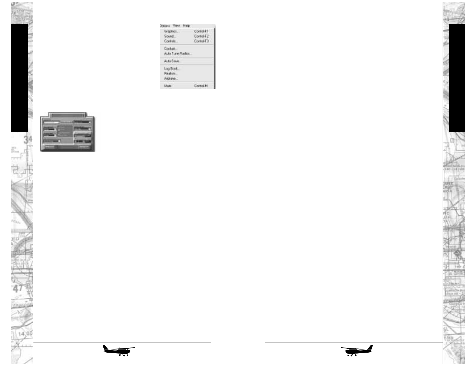
Options
While it is important to understand
these various options (especially if you are
getting unsatisfactory performance), you can
jump right into the sky with the default
options. We do not, however, recommend it.
Quick starters can simply head for their
plane once they have defined their Graphics,
Sound, and Control options, but all pilots will
benefit from understanding the following
information.
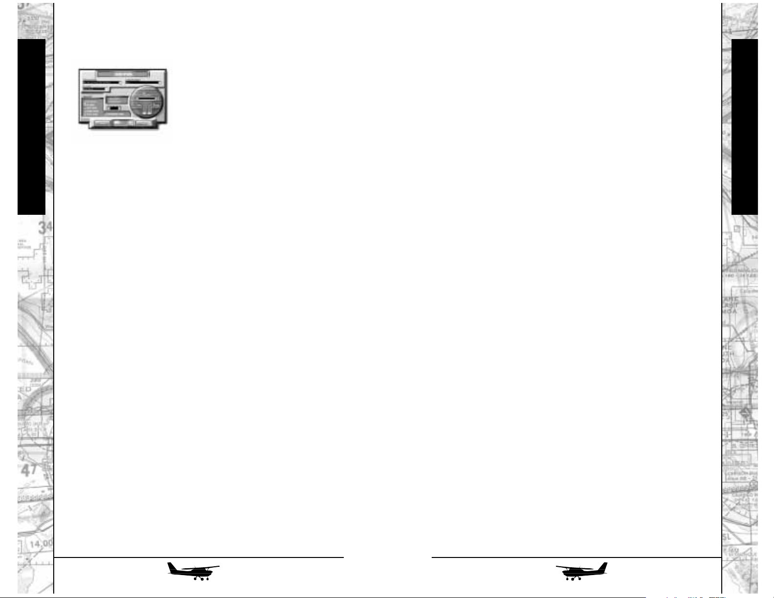
Graphics
These options tell Fly! which graphic
effects to generate, as well as what video
hardware is installed in your machine.
Whether you have 3D hardware installed or
not, you will want to review the options in
this box before you step into the cockpit for
the first time. The performance and frame rates of Fly! can be impacted most significantly by manipulating selections in this dialog.
Video Card
Use this pop-up menu to identify the brand and type of video
card you have installed in your computer. Fly! will automatically
configure visual effects based on the published capabilities of the
video card. If you do not have a 3D accelerator card installed,
select Software Only. If you have a 3D accelerator installed but it
is not listed here, you can select DirectX5 Compatible, DirectX6
Compatible, or 3Dfx Glide Compatible for defaults.
Startup Screen
This pop-up menu allows you to pick what screen you will
see by default when launching Fly! in the future. You may choose
between the Intro, Fly Now, Flight Planner, or Multi-Player Views.
If you always go to one of these areas when launching Fly!, you
will find it convenient to save your favorite as the simulation’s
start-up screen.
Scenery Detail
Increases or decreases the amount of graphic detail in Fly!’s
3D scenery. The levels of detail are: None, Sparse (includes only
major buildings), Normal (shows secondary landmarks, and well
known Points Of Interest), and Complex (displays all of the above
plus generic buildings for added realism). Lower this detail to
increase system performance.
Airport Detail
Increases or decreases the level of graphic detail in Fly!’s air-
port runways. Lower this detail to increase system performance.
Shadows
Specify which objects cast shadows onto the ground
scenery. The available selections are: None, Aircraft Only, and
Aircraft and Buildings. Turning off building shadows by selecting
Aircraft Only can significantly improve frame rates in areas of high
building concentration.
Checkboxes
Detail Tiles: Check this box to experience enhanced ground detail
around major airports. This requires considerable processor power
and video RAM. Turn off this feature to increase system performance.
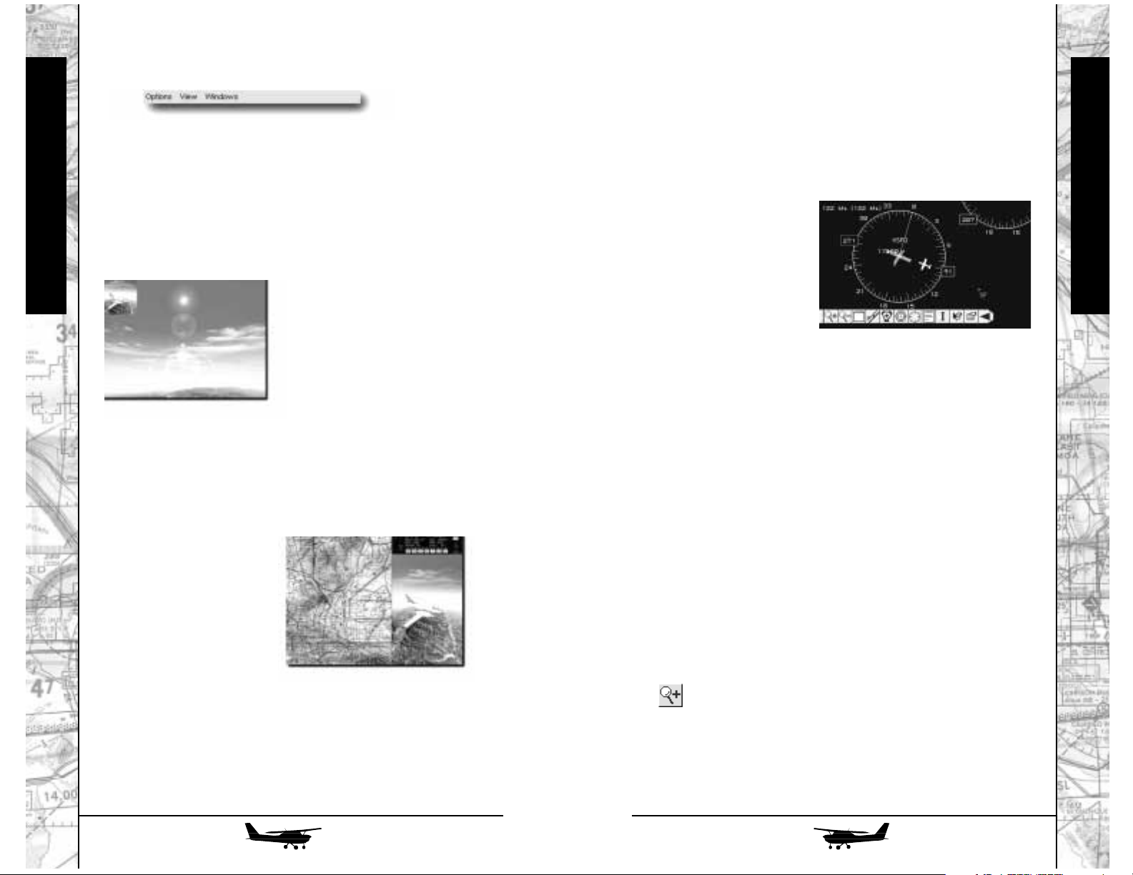
Lens Flare: Check this box to enable colorful lens flare effects projected from the sun. Turn off this feature to increase system performance.
Environment Mapping: This feature maps reflections of the sky,
clouds and ground onto the exterior of your aircraft resulting in a
more life-like look. Turn off this feature to increase system performance.
Auto Full Screen: If selected, this feature causes the simulation to
open in full-screen mode by default. If unchecked, the simulation
will open in a window. Note that any 3D accelerator hardware you
have installed will
not
be used unless you are running in full screen
mode. By activating Auto Full Screen, you ensure your hardware will
always be used by default. Running in software only modes will
result in significantly slower performance.
Terrain Visibility
This slider alters the maximum distance you can see from
your aircraft. Beyond this maximum distance, terrain will be
shrouded by haze. The setting ranges from 10 to 20 miles. Note
that this setting limits the Visibility setting in Environment—no
matter how high you set that slider, you will not be able to see
beyond the distance specified here.
Texture Cache Size
Slider changes the size of the simulation’s Texture Cache.
This cache blocks off a chunk of your available RAM for pre-loading of textures to speed rendering. The larger you set this cache,
the fewer “pauses” you will experience due to disk accesses during flight. You are limited in this setting by the amount of available
RAM in your computer. Values range from 8MB to 32MB. You
should be careful not to set this value too high if your machine has
a too little RAM installed.
Page 7
12
13
Simulation
Simulation
Sound
These options allow you to define
the sound hardware and specifications
for your system. Sound is a significant
element in an effective simulation, so
the higher you can move these settings,
the deeper your immersion in the flight
experience. Keep in mind that higher
sound settings will slow system per-
formance, so be prepared to lower them to remedy any stuttering
or slow frame rates.
Sound Device
This pop-up menu allows you to select which sound hard-
ware will be used to produce Fly!’s sound effects.
Quality
Quality settings range from 8-bit to 16-bit on this pop-up
menu. Reduce this setting to improve system performance.
Speaker Setup
Pop-up menu establishes whether your system supports
Mono, Stereo, or Surround sound.
Checkboxes
These options allow you to adjust the kinds of sound effects
you will hear. Using these options can impact sound card and system performance. Deactivate some or all of these checkboxes to
increase system performance.
Setup Sounds: Mood-setting background sounds that play while in
the simulation’s set-up menus. Click this box to activate or deactivate
these sounds.
ATC Sounds: Air Traffic Controller chatter plays while you are seated
in your cockpit. Click this box to activate or deactivate these sounds.
Turning off this option will not disable the scrolling ATC text displays,
allowing you to still receive critical ATC information without audio
output.
Engine Sounds: While in flight, your engine emits the satisfying,
familiar hum of a plane in flight. Click this box to activate or deactivate engine startup, idle, propeller, or shutdown sounds.
Aircraft Sounds: Besides engine sounds, each aircraft also produces
a range of other sound effects, including flaps, tire noise, stall horn,
and gear horn. Check this item to enable or disable these sounds.
Cockpit Sounds: While in the cockpit view, a variety of sound effects
are used to reproduce in-cockpit atmosphere. Effects include switches, marker beacon signals, ground noise, gyroscopes, and audible
alarms. Check this item to enable or disable these sounds.
Environmental Sounds: This check box controls the audio for wind,
rain, and thunder. Enable or disable as desired.
Volume Control
With this slider, you can increase or reduce the relative volume of all sound effects. The Left and Right indicators show the
sound output levels of each speaker attached to your system.
Radio
The Radio related checkboxes control the use of LiveMic™,
a feature that allows you to use voice communication with other
players when participating in multiplayer over the Internet. You
must have a microphone attached to your computer, as well as a
sound card that supports microphone input.
Full Duplex: Allows you to talk and listen simultaneously when using
two-way radio transmission. Requires a full duplex-capable sound
card (see your sound card’s manual to find out if yours is full duplexcompatible).
Compression: Toggles Radio compression on and off. Use compression if attempting to use two-way radio transmission over dial-up
Internet connections. If you are playing over a LAN, you probably
don’t need to turn compression on; sound quality will be clearer
without compression.
Amplification: Amplifies incoming two-way microphone audio.
Mute
Negates all volume controls.
Page 8

14
15
Simulation
Simulation
Controls
This dialog may be used to customize the simulation’s default keyboard and button assignments to suit
your personal style and preference.
The key list shows the name of
the simulation function in the left column, the currently defined keystroke
in the center column, and the currently defined joystick or controller button assignment in the right column. Any listed function
can be assigned to a keyboard shortcut, or to a button on a joystick or other input device.
Key Assignments
The various keyboard and button commands are divided
into sets for greater organization. Select from each of the following to find the commands you wish to customize (For more information on all these controls and their default key assignments,
Controls & Shortcuts, p. 41)
Menu Keys: Controls for the simulation’s general interface and menus.
Global Keys: Universal keys available regardless of aircraft being used.
Camera Keys: Controls for the movement and placement of cameras.
Airplane Keys: Controls for movement of your airplane and systems.
Slew Keys: Controls for placement of aircraft in Slew Mode. (p. 50).
Redefine Key
When you click on an item in the Assignments list, its currently assigned key appears in this text entry box. If you want to
change the key assignment, input it here. Be sure, however, not to
use a key already assigned to another function. To assign a button
to a function, simply select the function in the Key Assignments
list, then press the button on your controller.
Clear: Pressing this button clears the assigned keyboard shortcut and
controller button.
Load Set/Save Set
User-defined key configuration sets can be saved for later
use by pressing Save Set and can be recalled with the Load Set button. Fly! ships with a collection of pre-configured key configuration sets that match other competing flight products, to allow easier learning for users already familiar with these products.
Restore Defaults
Resets all keyboard/button assignments to their original
defaults.
Null Zone
This slider allows you to increase the realism of the simulation by creating a “null zone” on your input device. This zone, a
percentage of your device’s range of motion, creates a region
around the controller’s central point in which it will not respond.
The higher the percentage, the farther the device must be used
before the aircraft will respond. Null zone has no effect if you are
using the keyboard or a gamepad as your primary input device.
Setup Controls
Click this button to open the Setup Controls dialog, which is
used to select which joystick or input devices should control the
various axes for the aircraft.
- For Microsoft Windows users:
This dialog box allows you to
define what, if any, input devices you
intend to use with Fly! Input is divided
between General controls, Throttle,
Mixture and Propeller. Click the area
you wish to edit, which will then display the available axis inputs.
For each axis listed, choose the input device you want to
control that axis from the appropriate combo box. Once the input
device is selected, you can choose which axis on that device is
used to control the aricraft axis. Make this selection from the
appropriate combo box on the right. This allows complete customization of the input controls for FLY!
X-Axis: Select which input device will control the X-axis of the aircraft. The X-axis controls left-to-right banking of the aircraft through
the ailerons.
Y Axis: Select which input device will control the Y-axis of the aircraft. The Y-axis controls the nose up-nose down pitch of the aircraft
through the elevator.
Rudder: Select which input device will control the Rudder of the aircraft. The rudder controls left-to-right yaw.
Throttle: Select which input device will control the Throttle of the
aircraft.
Page 9

16
17
Simulation
Simulation
Left Toe Brake: Select which input device will control the left toe
brake in the aircraft. Certain rudder pedal input devices may not support this functionality.
Right Toe Brake: Select which input device will control the right toe
brake in the aircraft. Certain rudder pedal input devices may not support this functionality.
Trim: Select which input device controls the aircraft’s Elevator Trim.
Open Control Panel: Clicking this button opens the Microsoft Windows
joystick control panel to test and calibrate your input devices.
Engine Controls: Clicking the Throttle, Mixture and Propeller buttons
allows selection of input devices for each of these functions. You can
assign the same input axis to control multiple engines, or specify separate input axes for each engine.
- For Apple MacOS users:
This dialog box allows you to
define what, if any, input devices you
intend to use with Fly! This is the standard MacOS InputSprocket configuration dialog, allowing you to configure
and assign functionality to each input
device.
Click on an input device listed in the left column to display
the programmable functions for that device. Click on the icons to
open a pop-up menu allowing you to choose which function that
axis should map to. You should only use this dialog to assign
device axis input for Fly! For buttons and point of view configuration, use the Controls dialog to establish button assignments as
desired.
Cockpit Options
These options dictate how the cockpit
view and gauge detail will be presented in
the simulation.
Gauge Detail
Dictates the level of detail (frames of animation on needles,
compasses, etc.) presented on the cockpits’ array of dials and indicators. Normal, coarse, and minimal. Lower this setting to increase
system performance, particularly if you are running short of RAM.
Stretch Main Window
When active, this feature creates a realistic change of perspective when you scroll around the cockpit—the landscape seen
through your window will stretch as your perspective changes.
You may see a small performance increase when this feature is on.
Cockpit Window Full Width
Normally, if you resize your window while using a camera
other than cockpit, you will see the same resizing when you return
to your cockpit. When you activate this feature, your cockpit will
always be full-screen width.
Scroll with Mouse
Allows you to scan your instruments by moving your mouse
pointer to the edges of the screen. If you choose to disable this
option, you must use the Shift + Arrow Keys to look around your
cockpit (p. 41).
Tune Radios
Your radios are your navigational and
communications lifeline when you are high
in the sky. Use this dialog to select a radio
and tune by keyboard. The frequency you
enter will always be set as the “active” frequency for the selected radio. You always have the option of tuning the radios directly in-flight by directly manipulating the radio
with the mouse from the cockpit view. For more on using your
radios, see Radios, p. 44.
Select Radio
Pop-up menu allows you to choose from the available radios
installed in the currently selected airplane. Radios differ across different aircraft, so carefully browse this list to find the exact component you are wanting to tune.
Frequencies
Enter the frequency to set as the active frequency for the
selected radio. Fractional frequencies may be entered, but if a frequency is entered that is outside the tuning range of the selected
radio, the change will have no effect.
Page 10

18
19
Simulation
Simulation
Auto Save
This set of options allows you to
define which of your settings will be
automatically saved between sessions.
The next time you launch Fly! these settings will load by default, speeding your
return to flight. Each of these checkboxes
can be toggled to indicate which data you want saved automatically when you exit Fly!.
Flight Plan
Preserves departure and arrival airports and times, user-
defined waypoints, and flight paths.
Environment
Saves all environmental settings for clouds, wind, weather,
visibility, etc.
Simulation State
Saves the state of the simulation when you exit. You can
resume your flights in progress without saving manually.
Aircraft
Remembers the last selected aircraft.
Fuel
Preserves settings for fuel loadout for each fuel tank. Only
active if Aircraft has been selected.
Weight
Saves preferences for weight loadout for each passenger,
pilot, and cargo slot. Only active if Aircraft has been selected.
Ask Before Exiting
Select this check box if you want to be prompted before exit-
ing Fly!
Logbook
Real-world pilots log every hour
they spend in the air or on simulators to
demonstrate how much in-flight experience they have. The same mechanism is
available in Fly! Every moment in flight can be recorded so you
can trace your history and impress your friends.
Flight Entries
This list contains a history of each flight you have taken in
Fly! Each entry displays the date and time of flight, the aircraft in
use, and the flight duration.
New Log Book
Create a new log book. You will be asked to specify a location on your hard disk to save the new log book file.
Open Log Book
Opens an existing log book. The last log book you open
before leaving this dialog will be considered the “active” log book.
Details
Click the Details button to see complete details of the flight
entry currently selected in the Flight Entries list.
Realism
Fly! offers unprecedented realism in
a flight simulator, but many beginning
pilots may find these features cumbersome when learning to fly. Review the following realism elements to decide what
level of realism you expect from the simulation.
Detect Collisions
Activating this option makes all structures (i.e. buildings,
bridges, towers, and other aircraft) solid. With the feature enabled,
these structures can be hit by your plane. Deactivating it allows
you to pass through these structures.
Battery Drain
Normally, your battery is drained by the use of electronic
devices, reducing your power levels over time. When you turn off
this feature, your battery will have an infinite charge.
Dynamic Scenery
Turning this feature on allows the simulation to create computer controlled aircraft in the world around you. Turning this feature off can provide performance boost, but will also simplify the situation somewhat—if there are other planes in the air, you must be
mindful of their locations and co-exist with them during take-offs
and landings.
Page 11

Icing
Cold weather and high moisture levels can cause ice to form
on your wings, a runway, and aircraft parts, reducing airplane performance. Turning off this feature eliminates the possibility of ice
forming. When active, you will experience the effects of icing
when conditions are present, but there is no visual indication of
ice on the aircraft or outside surfaces.
Accurate Ground Traction
Simulation
Rain or ice can cause runways to become slick, making takeoffs and landings difficult. Turning this feature off eliminates this
hazard and preserves dry-weather conditions regardless of actual
weather.
Gyro Drift
Gyroscopic instruments have a tendency to lose accuracy
after extended use. Experienced pilots know how to adjust for this
“drift,” but it can be confusing to novices. You can disable this if
desired.
Accurate Engine Start
The procedure to set-up and start engines is a lengthy and
complicated one. When this option is enabled, pressing the Easy
Engine Start key will allow the plane to methodically turn on and
activate each aircraft system in order. This can be helpful when
learning the startup sequences for each aircraft. When disabled,
pressing the Easy Engine Start key will immediately start the aircraft with minimal delay.
Manual Propeller
Pilots often need to adjust propeller RPM, but you can let the
computer make these changes if you deselect this feature.
Airplane
These options encompass the fine tuning necessary to ready a plane for flight. Be
sure to adjust these before flight, or leave
them at their default settings if you are unsure
how to adjust them. Note that these changes
only affect the currently selected aircraft, and
do not affect all other aircraft. This allows for
distinct input tuning for each aircraft individually.
Trim Sensitivity
Moving this slider makes any adjustments to trim (in other
words, each press of the key controlling that adjustment) less significant. As a result, pressing the Elevator Trim Up key would have
less effect if Trim Sensitivity is adjusted to the left. If you wish your
adjustments to have a more dramatic effect, move this slider to the
right. To tie Elevator, Aileron and Rudder Trims together, click the
Lock Settings checkbox.
Control Exponential
This factor dictates how much effect holding the following
controls will have. In other words, the longer you hold the adjustment, the faster it adjusts. Moving the slider to the left causes controls to accelerate at a slower rate, moving it to the right causes
acceleration to increase. To tie all three settings together, click the
Lock Settings checkbox.
Mute
Mutes all sound. This can also be activated by pressing
Control-M in Windows or Command-M in MacOS. Selecting
Mute again restores volume to previous levels.
Simulation
20
21
Page 12

23
Simulation
22
Simulation
Directory
Use this tool to jump to any
geographical point (airport, navpoint, etc.). The directory is a
stripped-down version of the
Departure/Arrival Dialog Box
(see Flight Planner, p. 32).
Toggle cockpit
When in Cockpit view, use
this feature to hide your entire
instrument panel from view.
When the panel is turned off,
you will have a full-screen view
of the landscape in front of your
aircraft. To maintain your essential controls, you might want to
bring up your Mini-Cockpit
Window (p. 30).
Intro Screen
Links to the Intro Screen View, (p. 8).
Fly Now!
Links to the Fly Now! View, (p. 31).
Flight Planner
Links to the Flight Planner, (p. 32).
Setup Aircraft
Links to the Setup Aircraft View, (p. 36).
Environment
Links to the Environment View, (p. 38).
Toggle Full Screen
Switches between full-screen, zoomed in-window and
desktop in-window modes. Keep in mind that 3D hardware
acceleration will not be used when running in windowed modes,
resulting in lower frame rates.
Cockpit Camera
For most pilots, this will be their primary view of the world.
From this view, you can look around your cockpit as freely as if you
were there (especially if you have mouse scrolling activated, see
Scroll with Mouse, p. 15).
Spot (Chase) Plane Camera
This is a free-motion camera. Activating it immediately
transports you outside your
plane to watch it in flight. Use
the camera control keys to zoom
and pan around until you find
the view that suits your needs.
You can even save your favorite
positions to a hot key.
Fly By Camera
This is a stationary camera
that observes your plane’s
approach, pass-by, and departure. When you go out of range
of the camera, it assumes a new
position and starts its pan again.
View Menu
Page 13
Simulation
Simulation
You can scroll around the window by holding the Shift Key
(turning your mouse pointer into a grabbing hand) and clicking to
grab and drag the map. You may also use the camera control keys
(i.e. Control + Right Arrow). Double click anywhere on the map
to re-center the map on your plane. Finally, you can click and
drag to see distance measurements.
Vector Map Window
The Vector Map is a
graphic display that illustrates nearby airports, VORs,
and NDBs in vector format.
The Vector Map is a resizable window that allows
viewing up to 150 nautical
miles in radius from the airplane’s position. In the event that you have no visible navigation
aids from the airplane’s view, use the Vector Map to quickly find
a reference navaid to guide you on your way. Highlight a navaid
in the Vector Map by moving the mouse over the navaid. Doubleclick on a highlighted navaid to open an information window
about the corresponding navaid. The Vector Window is one of
FLY!’s most flexible tools. Explore the array of features, buttons,
and aids freely and frequently.
Control Bar
The Control Bar provides a method to quickly modify the visible
navaids in the Vector Map. The Control Bar is located at the bottomleft of the vector map. The Control Bar can be opened or closed.
When the Control Bar is closed (collapsed) it displays an arrow
pointing to the right. Click on the right arrow to open (extend) the
Control Bar. The Control Bar in the open position displays an assortment of buttons. The arrow previously pointing to the right now
points to the left. Click on the left arrow to close the Control Bar. The
arrow previously pointing to the left now points to the right. The button functions are described below from left to right:
Zoom-In: Click the Zoom-In button to increase the amount of
visible area in the Vector Map while increasing the
size of the items visible. Click and hold the ZoomIn button to zoom at an increasing rate. When the
Vector Map is at maximum zoom, the Zoom-In button becomes disabled.
Windows
This menu contains all of the simulation’s special Windows.
These alternative views provide powerful and flexible tools that
every pilot should learn to use. For example, you can bring up a
sectional map of your current location to find out where you. Or,
you can call up a miniature version of your cockpit so you can
control your plane while using an external camera. These
Windows are:
Secondary Camera Window
This window displays
any of the external camera
views. For example, if you
want to be seated in the pilot’s
seat, but still want to watch
your plane from the outside,
you can bring up this window
to view the Spot Plane
Camera. You can scroll
through the available camera views as normal by pressing C.
When the Secondary Camera Window is the active window, it
receives all camera keystrokes. Some 3D accelerator cards do not
support this feature.
Map Window
Opens a window displaying your plane centered
over a sectional map of your
immediate area. With this
tool, you can immediately
confirm your location or
locate nearby navaids, airports, or major terrain features. Fly! ships with sectional charts covering the
continental United States.
25
24
Page 14

Simulation
Simulation
Compass Plate: Click the Compass Plate button to enable or disable
the display of compass plates on all VOR navaids.
The compass plate is displayed as a green circle
with a radius between one and five nautical miles.
The compass plate circle is scaled appropriately
when the Vector Map is zoomed. A solid green line
points from the middle of the circle to magnetic
north. Along the perimeter of the circle are marks at
intervals of 30º, 10º and 5º. The Bearing To and
Radial From are displayed on the perimeter of the
circle. Flying the Bearing To directs your plane to the
compass plate along an imaginary line from your
airplane to the center of the circle. If you get lost
while flying, find a nearby compass plate and fly at
the Bearing To to resume your flight plan.
Text Labels: Click the Text Labels button to enable or disable
navaid labels. The amount of information in the text
label of each navaid type can be set in the Options
Screen.
Graphics Mode: Click the Graphic Mode button to toggle the display
of icons or colors for navaids. When displaying
icons for navaids, an icon appears in the Vector Map
corresponding to the type of navaid. The icons are
the same icons found in the Flight Planner, for more
information, see Map Icons p.34. When displaying
colors for navaids, airports are yellow, VOR navaids
are green, and NDB navaids are red.
Cursor Info: Click the Cursor Information button to display the
specified information near the mouse cursor. The
exact information displayed near the mouse cursor is
set in the Options Screen. The settings include the
distance from the airplane to the mouse cursor, the
radial from the airplane to the mouse cursor, and the
bearing to the mouse cursor from the airplane. All the
information is calculated from the center of the airplane to the tip of the mouse cursor. Click the Cursor
Information button again to disable the option.
Options: Click the Options button to display the Options
Screen. The options screen allows you to specify the
visuals in the Vector Map. The Vector Map Window
resizes to accommodate the Options Screen. The
options are described in more detail in Vector Map
Options, p.28. Click the Options button again to
close the Options Screen and restore the Vector Map
Window to its previous size.
Zoom-Out: Click the Zoom-Out button to decrease the amount
of visible area in the Vector Map while decreasing
the size of the items visible. Click and hold the
Zoom-Out button to zoom at an increasing rate.
When the Vector Map is at minimum zoom, the
Zoom-Out button becomes disabled. The maximum zoom out allows a 150 nautical mile visible
radius from the airplane.
Maximize/Restore: Click the Maximize/Restore button to quickly max-
imize the Vector Map to full size of the screen or
restore it to its previous size. Click the button to
maximize the window. Click the button again to
restores the window to its previous size.
Airport: Click the Airport button to enable or disable the
display of Airport navaids in the Vector Map. The
Airport appears as a yellow vector Airport when in
colored graphic mode, or as the appropriate
Airport icon when in icon graphic mode. As the
Vector Map is zoomed in, the Airport (in colored
graphic mode) displays runways. When the Vector
Map is close to maximum Zoom-In, runway identifiers are displayed at the ends of the runways,
helping you to find the appropriate runway when
attempting to land. Double-click an airport to open
an Airport Information Window about the corresponding airport.
VOR: Click the VOR button to enable or disable the dis-
play of VOR navaids in the Vector Map. The VOR
appears as a green vector VOR when in colored
graphic mode, or as the appropriate VOR icon
when in icon graphic mode. The display of compass plates is disabled when VOR navaids are disabled. Double-click a VOR to open a Navaid
Information Window about the corresponding
VOR.
NDB: Click the NDB button to enable or disable the dis-
play of NDB navaids in the Vector Map. The NDB
appears as a red vector NDB when in colored
graphic mode, or as the appropriate NDB icon
when in icon graphic mode. Double-click a NDB to
open a Navaid Information Window about the corresponding NDB.
27
26
Page 15

Simulation
Simulation
Text Labels: Toggles the display of text labels on and off.
Compass Plate: Toggles the display of compass plates on VOR
navaids.
Cursor Info: Toggles the display of information near the mouse
cursor.
Cursor Distance: Toggles the display of the distance from the airplane
to the mouse cursor. The information is displayed
near the mouse cursor.
Cursor Bearing To: Toggles the display of the bearing from the airplane
to the mouse cursor. The information is displayed
near the mouse cursor.
Cursor Radial Toggles the display of the radial from the airplane
From: to the mouse cursor. The information is displayed
near the mouse cursor.
Time: Toggles the display of the time.
Date: Toggles the display of the date.
Speed: Toggles the display of the indicated and true air
speed of the airplane.
Altitude: Toggles the display of the altitude of the airplane.
View Distance: Toggles the display of the visible distance.
Lat/Lon: Toggles the display of the latitude/longitude of the
airplane.
Graphics: Toggles the display of the navaids to either colors or
icons.
Cursor Distance Toggles the distance measurement used in all dist-
Measurement: -ances displayed in the Vector Map. These distances
include the cursor distance and visible distance of
the Vector Map. The measurements are as follows:
Feet (ft), Meter (m), Kilometer (km), Statute Mile (mi),
Nautical Mile (nm).
Compass Plate The plus and minus buttons increase and decrease
Size: the size of the compass plate respectively. The max-
imum compass plate size is 5.0 nm. The minimum
compass plate size is 1.0 nm.
On-Window Text
The Options Screen allows you to selectively display information
about your flight. The information is displayed at the top of the Vector
Map and is divided into 3 sections. The sections include the top-left,
top-middle, and top-right of the Vector Map.
The date and time, air speed and true air speed, altitude and elevation are found in the top-left section of the Vector Map. The time is
displayed in UTC (Coordinated Universal Time - Zulu). The air speed
is the speed of the airplane without the effects of nature. The true air
speed combines the speed of the airplane with the forces of nature
(i.e. wind, gravity, etc.) acting on the airplane. The altitude is the
height of the airplane relative to sea level. The elevation is the height
of the airplane relative to the ground directly beneath it.
The distance of the view area is displayed in the middle section of
the Vector Map. The distance is measured from the airplane to the
left edge of the Vector Map followed by the distance of the airplane
to the top edge of the Vector Map (i.e. 150 nm x 150 nm). For
instance, zooming into the Vector Map increases the scale of the
Vector Map which decreases the viewable distance.
The longitude and latitude of the airplane is displayed in the top-right
section of the Vector Map.
Vector Map Options
Click the Options button on the control bar to display to Vector Map
Options Screen. The Options Screen allows you to configure the
Vector Map to your taste. All option states are saved when modified.
When you return to your Vector Map from session to session, it
appears as you left it. The following describes each option found in
the Vector Map Options Screen:
Airport: Toggles the airport visual on and off.
Airport Name: Toggles the airport name label on and off.
Airport Identifier: Toggles the airport identifier label on and off.
VOR: Toggles the VOR visual on and off.
VOR Name: Toggles the VOR name label on and off.
VOR Identifier: Toggles the VOR identifier label on and off.
VOR Frequency: Toggles the VOR frequency label on and off.
NDB: Toggles the NDB visual on and off.
NDB Name: Toggles the NDB name on and off.
NDB Identifier: Toggles the NDB identifier on and off.
NDB Frequency: Toggles the NDB frequency on and off.
29
28
Page 16

Simulation
Simulation
Help
This help menu links users with Internet connections directly
to a variety of Web Sites which can assist you with troubleshooting
and updating Fly! Windows users will also see the “About Fly”
menu in this location. Look to these sites for assistance.
• Fly! Support Page
• Terminal Reality Inc. Home Page
• Gathering of Developers Home Page
Fly Now
Fly Now is primarily for
novice pilots, allowing them to
jump right into the aircraft
without having to establish a
flight plan, but it is also for the
veteran who just wants a quick
fix of flight. Whatever the reason, this is the fastest way to get
yourself into the air.
Scenario
The scenarios in Fly Now are all predefined, meaning that
your plane, weather and load considerations are already established. All you need to do is pick which scenario you desire and
take off. Scan this list for the plane and location you wish to fly and
click once to highlight it.
Category
The category pop-up menu is used to help classify scenarios
for easy location. This feature is intended for third-party add-on
product expansion. By default, leave the pop-up selected to “<All
Scenarios>” or “FLY! Defaults” to view FLY! original scenarios.
Details
This button accesses a description of the scenario.
FLY
Transfers you to the cockpit of your plane to fly the selected scenario—be sure you have chosen the correct scenario before
you press this button. Many of the scenarios that ship with Fly!
begin with the plane in the air, but some start on the ground,
requiring you to take off but allowing you to bypass the engine
start-up procedures.
Axis Window
Brings up a visual representation of your
axis readings and trim tab settings. This window will stay on screen even if you switch to
another view. The window has three sets of
indicators: the vertical bar represents your
elevators, the top your ailerons, and bottom
your rudder. White arrows show current posi-
tion of control input (either keyboard or joystick) and orange
arrows show current trim settings. The ALT button (on the Axis
Window, not on your keyboard) activates Altitude Hold, an
autopilot-like setting that maintains your current rate of Altitude
change (not your current altitude). The WING button activates the
Wing Leveler. AC activates the Auto Coordination (keeps aileron
and rudder turns coordinated)—recommended for keyboard users.
Finally, TRIM activates auto-trim for the aircraft. However, since
this feature will attempt to auto-trim the plane in all circumstances, only turn on when necessary.
Mini Cockpit Window
Whether you want to have access to your controls even
when using an external camera or you simply don’t want a full
instrument panel blocking your view, you can bring up this window. It contains six essential controls (Airspeed Indicator, Altitude
Indicator, Attitude Indicator, CDI, Compass, NAV/COM Radio,
Throttle Lever, Propeller Lever, and Mixture Lever) at the bottom of
the screen. This window will stay on screen even if you switch to
another view.
GPS Window
Brings up a full scale view
of the Bendix/King KLN89 GPS
radio (when applicable). This
allows for easier direct input
using the mouse, and also allows
for GPS access when not using the cockpit view. You can optionally open this window by double clicking inside the faceplate of
the GPS on the primary cockpit panel.
31
30
Page 17

Simulation
Simulation
• Airport Detail
This chart displays the currently selected airport and many
of its details.
Name: Name of the airport.
FAA or ICAO ID: Airport identification code.
Usage: Whether the airport is public or private.
Elev.: Elevation of the airport above or below sea level.
Country: Country in which the airport is located.
State: State in which the airport is located.
• Runway
This box lists the available runways at the selected airport.
The line drawing to the right represents the runways and their
configuration.
ID
Lists the identification number for each of the selected airport’s runways. As you highlight a runway in this box, the line drawing to the
right illuminates to indicate the runway you have chosen.
Size
Indicates the size of each runway in feet.
Details Button
Calls up information on a selected airport including com frequency,
name, location, elevation.
Departure Time
Specify your desired departure time here in Departing From dialog
box. This time should be entered in Coordinated Universal Time
(UTC), or Zulu time.
• Pointers
These tools located in a vertical stack along the left side of
the screen allow you make changes to your flight plan within the
map window.
Arrow A pointer for use within the map box. Used to
select or view details of items on the map.
Arrow + This tool enables you to add elements to your
route. Click on the navigational aids you would like to add to
incorporate into your plan.
Arrow – This tool removes elements from flight plan. To
use, click on the element you wish to remove.
Flight Planner
The Flight Planner is the
interface for more advanced
pilots who want to define many
of the aspects of their flying
experience: route, plane, load,
weather, etc. Beginning a flight
this way requires substantial
experience and knowledge
(consult this manual liberally if
you have any doubts), but
many options can simply be left in their default position.
• Departing From/Arriving At
Click on these buttons to define your departure airport and
time and arrival airport. Note that these dialog boxes are essentially the same with differences noted below.
Search For
Choose the type of facility you wish to search for. When accessing
this dialog from the Flight Planner, only Airports can be searched.
Country
Select which country you would like to depart from. Making this
choice will bring up a list of available airports in the Airport Detail
chart below. Most of the world’s countries are included on this list.
State
If you chose “United States” from the Country pop-up menu, you will
next be able to choose your state of departure. This pop-up menu will
be unavailable if you have chosen any other country.
Name
If you know the name of your desired airport, you can simply enter it
in this text box. If no keystrokes are entered within a second, the
search will automatically be executed.
FAA or ICAO ID
If you don’t know the name of your chosen airport, but do know its
FAA or ICAO identification code, you may enter that code here. If no
keystrokes are entered within a second, the search will automatically
be executed.
Favorites
This section allows you to save any search result for quick selection
or airport lookup in the future.
Search Sets: Click on this pop-up menu to chose from all favorite
sets you have already defined. When you chose an airport on the
list, it will appear in the Airport Detail Chart below.
Add Set: This button adds an airport displayed in the Airport Detail
Chart to your Favorites list.
Remove Set: This button removes the last selected set (shown in
the popup-menu) from your Favorites list.
33
32
Page 18

Simulation
Simulation
NDB-Concentric circles
NDB with DME-Circles with blue square center
VOR-Hexagon with blue center
VOR with DME-Hexagon with square center
VOR with Vortac-Hexagon with bold edges
Detail Options
Allows you to filter out many of the details brought up by
activating the overlays. The number of airports, navaids, etc. can
be a bit overwhelming, so this feature can help clear up the clutter of the map view.
______ Detail
This button changes depending on what kind of symbol is
most recently clicked upon in the map window. Airports, Navaids,
Waypoints, and flight segments can contain details of each specific item which are accessed via this button.
Edit Route
Pressing this button brings up a box listing all airports and
waypoints on your route from point A to point B. From here you
can select each point individually to change them as you deem fit.
Generate Route
Automatically generate routes by simply specifying the
Departure and Arrival Airports. Using this tool, however, overrides
any other flight plan information.
Setup Aircraft and Environment
Links to appropriate section (p.36 and 38).
FLY
Initiates the flight plan you have prepared and transports you
to the cockpit of your plane to begin startup procedures. Be sure
that all of your flight plan settings, including Environment and
Setup Aircraft settings are established before pressing this button.
Magnifying Glass Allows you to magnify an area of the map by
clicking on it. To zoom out, Control+Click with the mouse. The
behavior of this tool depends on whether you are looking at a vector
display or a map: in map mode, zooming will select the next most
detailed map (i.e. clicking on North America on the world map will
jump to the map of North America). Note that the “next most detailed
map” may not necessarily be a higher scale than the previous map,
it may simply cover a smaller area. Use the Detail Map Overlay to
see where maps intersect.
Map Icons
The two icons in the lower left corner of the screen indicates
which maps you will see in the map window.
Map Overlay: Pressing this button toggles the topographical map on
and off.
Detail Map Overlay: Pressing this button toggles a map overlay
that indicates the location of detail maps. If an area is shaded in
blue, there is a map available for that region.
Current Map: Indicates which map is currently open.
Detail Map: Pop-up menu to choose a different map.
Overlays
These map overlays provide useful navigational information by
plotting various elements onto the map window. Click on each
overlay button to toggle the switch on (illuminated) or
off (shaded).
Latitude Longitude Guide: Overlays longitude and latitude lines on topographical maps only.
Weather: Displays temperature, wind speed, and wind direction.
Only functions if METAR data has been imported from the
Environment screen.
Route Chosen: Overlays your flight route.
Waypoints: Overlays all available waypoints as locations on the
map. Represented as triangles.
Airports: Overlays all available airports as locations on the map.
Represented as crossed runways or as FAA-defined representation of
the runway layout.
Navaids: Overlays all available Navigation Aids (or “NAVAIDS”) as
locations on the map. Navaids come in five varieties. The symbol in
the left column represents the symbols as they are shown on standard
aviation maps and the symbols in the right column are their interface
equivalents. The latter are designed to be as similar as possible to
their actual counterparts, but there are some small differences:
35
34
Page 19

Simulation
Simulation
Uniform Fill-On/Off: Activating this feature allows you to fill all
tanks in the order they should be filled with one adjustment (on by
default) and assures that any changes in fuel level will affect the
weight distribution of the craft evenly. If, however, you wish to offset
a weight imbalance due to cargo or passenger load, you may do so
by turning Uniform Fill off and specifying different fuel levels to offset the weight. When you turn off Uniform Fill, individual fuel level
sliders will appear below each tank allowing you to make adjustments independently.
Total Fuel Level: This slider allows you to fill all tanks when Uniform
Fill (see above) is on. When Uniform Fill is off, you may not use this
slider to fill the tanks, but it will rise and drop as you add fuel to the
individual tanks to indicate changes to the aircraft’s total fuel level.
Total Fuel/Max Fuel: Numerically indicates the total fuel loaded onto
the aircraft and the maximum amount the plane can hold. Keep in
mind that the amount of fuel you can carry is limited not only by
these numbers, but by the total weight capacity of your aircraft - it is
possible to exceed weight capacity while having less than maximum
fuel loaded.
Setup Aircraft: Returns to Setup Aircraft (see above).
Load Out Weight: Links to Load Out Weight (see below).
Weight
Center of Gravity: These indicators display the balance of the aircraft
both front-to-back (“Fore and Aft”) and side-to-side (“Left and Right”).
The placement of fuel and weight (see Fuel Load Out above) impacts
these readings. Ideally, you want to keep the aircraft balance within
the green area of the indicator, as close to center as possible. If
weight is not evenly distributed, it will impact the aircraft’s flight stability. The dial shows red to indicate serious weight or balance problems.
Pilot, Passenger, and Cargo Icons: You can distribute weight in your
plane graphically by clicking on pilot seats, passenger seats, or cargo
bays to add or remove occupants of those sections. For example, you
can click on a chair to add a passenger. Watch the effect placing and
removing objects has on the Center of Gravity indicator above and
the Total Weight indicator below. Please note that although you may
add and remove passengers from the plane, you will only see a single occupant in the 3D aircraft when flying the simulator.
Setup Aircraft
To choose and configure
an aircraft for flight, you must
first select the aircraft you wish
to fly and then access the aircraft
fuel and weight options from this
screen.
Types to Display
All aircraft shipped with Fly! are categorized by their engine
configurations. This pop-up menu allows you to see all of the
available planes (“All Aircraft”) or only aircraft of a specific type
(Single-Engine, Multi-Engine, Single-Engine Turbo-Prop, MultiEngine Turbo-Prop, and Jet).
Details
Once you have selected an aircraft, its image appears in the right hand
window. Click on the Details button to
view selected performance information
for the aircraft.
Load Out
Load Out is the weight load and distribution of all things carried by the aircraft including, for example, cargo, pilots, passengers, and fuel. All of these elements can be customized and placed
by use of the two Load-Out screens: Fuel and Weight.
Fuel: Fuel Load Out allows you to specify the amount and placement of fuel in your aircraft.
Center of Gravity: These indicators display the balance of the aircraft
both front-to-back (“Fore and Aft”) and side-to-side (“Left and Right”).
The placement of fuel and weight (see Weight Load Out below)
impacts these readings. Ideally, you want to keep the aircraft balance
within the green area of the indicator, as close to center as possible.
If weight is not evenly distributed, it will impact the aircraft’s flight
stability. The dial shows red to indicate serious weight or balance
problems.
Fuel Tank Icons: Each aircraft has a number of fuel tanks located
around the plane, represented in this screen by ovals with a red fuel
symbol. The level of fuel in the tank is indicated by the gold coloring
that rises or drops as fuel level is changed.
37
36
Page 20

Simulation
Simulation
beyond your maximum visibility range. Visibility settings range from
0 to 20 miles. This setting can affect system performance but will
have no effect on aircraft performance. Note that this setting is limited by the Maximum Visibility setting in the Graphics Options dialog
(p. 11).
Temperature: External temperature can have profound effects on
your airplane. Cold temperatures increase the chance of icing. Hot
temperatures, on the other hand, render the air less dense and less
able to support a plane in flight. Temperatures range from -50°F to
120°F.
Pressure: Indicates the outside barometric pressure at sea level.
Pressure can impact the accuracy of altitude readings - if pressure is
high, actual altitude will be lower than is shown on instruments. If,
for example, you land at an airport that is at a different elevation than
your airport of origin, you will have to adjust the Kollsman window
on altimeter from the primary cockpit panel. This is particularly
important in IFR (Instrument Flight Rules) flight. Pressure settings
range from 28.0 Hg to 31.0 Hg.
Wind
Few things have more impact on flying than wind. Wind
affects speed adjustments, fuel efficiency, and take off and landing
directions. You can manually set the direction of the wind by
clicking on any point within the compass.
Variable Wind Direction: Click in this box to randomize the direction of the wind for greater realism. Activating this feature overrides
any settings made on the Wind Direction dial. The dial sets the predominant wind direction. Selecting variable winds allows the wind
to “blow” from more than one direction but it still maintains the predominant direction.
Average Speed: Slider establishes the average wind speed in the simulation. Wind will change speed constantly, occasionally rising
above or below this average, but this figure represents the general
steady airspeed. Speeds range from 0 MPH to 50 MPH.
Gust Speed: You can set the peak level for wind gusts with this slider, establishing the maximum spikes for wind effect.
Clouds
You can set the cloud count at three layers of atmosphere
with these text boxes and pop-up menus. Cloud layers can be set
to your preference (in feet) and cloud density can range from Few
to Scattered to Broken to Overcast. To activate these features, first
click on the Sun icon to the left of each layer to activate clouds at
that level. You may then set cloud density and altitude manually
in the pop-up menu and text box respectively.
Name, Type, Weight: These fields act as both an alternative way to
insert people and cargo into your plane and as a means of modifying
items already placed. To place a new object, choose its Name (i.e.
Co-Pilot, Left Rear Passenger) and Type (Pilot, Passenger, Cargo or
none) and specify its weight. To change an already placed object,
select its position from the Name pop-up menu or highlight it by
pointing at it and make any changes in these boxes. Most often, you
will want to raise or lower the weight of objects to balance out the
weight load. Keep in mind that the pilot (you) cannot be removed
from the plane.
Total Weight/Max Weight: Numerically indicates the total weight
currently loaded on your aircraft (including fuel) and the maximum
weight your aircraft can carry. Note that you cannot exceed the maximum amount and that heavier loads will affect airplane performance. The dial shows red to indicate serious weight or balance problems
Setup Aircraft: Returns to Setup Aircraft (see above).
Load Out Fuel: Links to Load Out Fuel (see above).
Flight Planner: Links to Flight Planner (p. 32).
Environment: Links to Environment View (p.38).
FLY: Takes you to the cockpit of your plane. Be sure all settings in
this section as well as Environment and Flight Planner are to your
liking before embarking on your journey.
Environment
Ever wanted to control the
weather? With the Environment
interface, you can. Keep in
mind that these settings will be
established worldwide and will
not change no matter how long
or where you fly. For greater
realism, however, you can
allow Environmental settings to
be established with real weather data by activating the METAR feature, described below.
Options
These sliders allow you to alter various weather attributes,
each of which can dramatically impact on aircraft performance.
Visibility: Visibility is the distance the pilot can see from the cockpit
- the higher the visibility, the farther the pilot can see. As visibility
decreases, objects in the distance will be shrouded in haze if they are
39
38
Page 21

Simulation
Simulation
Keyboard Controls &
Shortcuts
System Controls
Pause . . . . . . . . . . . . . . . . . . . . . . . . . . . . . . . . . . . . . . . . . . P
Access Menu Bar . . . . . . . . . . . . . . . . . . . . . . . . . . . Space Bar
Toggle Full Screen Mode . . . . . . . . . . . . . . . . . . Control + Enter
Exit to User Interface . . . . . . . . . . . . . . . . . . . . . . . . . . . Escape
Mute. . . . . . . . . . . . . . . . . . . . . . . . . . . Windows: Control + M
. . . . . . . . . . . . . . . . . . . . . . . . . . . . . . MacOS: Command + M
Graphic Options Dialog . . . . . . . . . . . . . . . . . . . . Control + F2
Sound Options Dialog . . . . . . . . . . . . . . . . . . . . . Control + F3
Control Options Dialog. . . . . . . . . . . . . . . . . . . . . Control + F4
Saving Screen Shots . . . . . . . . . . . . . . . . . . . . . . Control + Tab
Displaying frame rate and status information . . . . . . . . . . . . Tab
Cockpit Controls
Scrolling Cockpit Views
If you have Scroll with Mouse selected in Options - Cockpit,
you may simply move the mouse pointer to the edges of the screen
to scroll in the desired direction. Or you may use any of the following keyboard commands.
Scroll Cockpit Up. . . . . . . . . . . . . . . . . . . . . . Shift + Up Arrow
Scroll Cockpit Down . . . . . . . . . . . . . . . . . Shift + Down Arrow
Scroll Cockpit Right . . . . . . . . . . . . . . . . . . Shift + Right Arrow
Scroll Cockpit Left . . . . . . . . . . . . . . . . . . . . . Shift + Left Arrow
Head Pitch/Seat Adjust Down . . . . . . . . . . . . . . . . . . . . . . . . . ]
Head Pitch/Seat Adjust Up . . . . . . . . . . . . . . . . . . . . . . Shift + ]
Home Cockpit . . . . . . . . . . . . . . . . . . . . . . . . . . . Shift + Home
Show Backdrop
Activating this checkbox will introduce a photographic
background of distant clouds and horizon into the simulation. This
alone has no effect on weather conditions, but is simply a visual
option to enhance the “out the window” view.
Precipitation
Use the Precipitation pop-up menu to select the type of precipitation you desire: Clear (or None), Rain, or Snow. Precipitation
can obscure vision, alter airplane performance, and increase take
off and landing hazards.
Intensity
Precipitation intensity can be defined using this pop-up
menu and can be set to Light, Medium, or Heavy. The more
intense the precipitation, the greater the impact on the simulation.
As a note, to introduce Thunderstorms into the environment, set
Rain as the precipitation type and Heavy as the intensity.
Import METAR
To create more realistic weather conditions, you can add
real-world weather by importing weather reports based on the the
National Weather Service “METAR” files. Each METAR file
describes latest weather observations from one of thousands of
reporting stations around the world.
When you fly within 140 miles of one of these stations, the
weather will change to reflect the actual weather in that region
and if you are within the range of more than one station, the
weather will be interpolated from all nearby stations. If, finally,
you fly out of range of any stations, the weather settings will revert
to your manually defined Environmental settings.
Pressing the Import METAR button brings up a file box allowing you to choose which METAR files to import. Locate and open
the METAR file you wish to import. Once you import a new
METAR file, and previously imported METAR data will be lost.
METAR files can be obtained from a number of sources. A
few come installed with your copy of Fly!. If you desire other files,
they can also be obtained from various sites on the Internet including those of NOAA (the National Oceanographic and Aeronautics
Administration) and many popular flight simulation Web sites.
Clear METAR
Clears METAR settings and reverts to your manually defined
Environmental settings.
You may also link to Setup Aircraft, Flight Planner and FLY.
41
40
Page 22

Simulation
Simulation
Elevator
Elevator Up . . . . . . . . . . . . . . . . . . . . . . . . . . . . . Down Arrow
Elevator Down . . . . . . . . . . . . . . . . . . . . . . . . . . . . . Up Arrow
Elevator Trim Up . . . . . . . . . . . . . . . . . . . . . . . . . . . . . . Num 1
Elevator Trim Down. . . . . . . . . . . . . . . . . . . . . . . . . . . . Num 7
Engines
Using this feature will automatically perform system and
engine startup. If you have turned on “Accurate Engine Start” in
Realism (p. 20), you will have to wait while the computer performs each of the startup steps in sequence. If not, the engine will
start up instantly.
Easy Engine Start . . . . . . . . . . . . . . . . . . . . . . . . . . . . . . . . . . E
Flaps
Retract Flaps . . . . . . . . . . . . . . . . . . . . . . . . . . . . . . . . Shift + F
Extend Flaps . . . . . . . . . . . . . . . . . . . . . . . . . . . . . . . . . . . . . F
Fuel
Mixture Down . . . . . . . . . . . . . . . . . . . . . . . . Control + Num 3
Mixture Up . . . . . . . . . . . . . . . . . . . . . . . . . . Control + Num 9
Gear
Up/Down . . . . . . . . . . . . . . . . . . . . . . . . . . . . . . . . . . . . . . . G
Force Down. . . . . . . . . . . . . . . . . . . . . . . . . . . . . . . . Shift + G
Heat
Carburetor Heat On/Off . . . . . . . . . . . . . . . . . . . . . . . . . . . . H
Pitot Heat On/Off. . . . . . . . . . . . . . . . . . . . . . . . . . . . Shift + H
Miscellaneous Controls
IFR Hood On/Off . . . . . . . . . . . . . . . . . . . . . . . . . . . . . Shift + I
Only available in the cockpit view. Turns off all 3D drawing
outside window. Essentially, allows for blind flying under IFR
(Instrument Flight Rules) by pulling a blinding hood over the cockpit window.
Prop Pitch Decrease. . . . . . . . . . . . . . . . . . . . Control + Num 1
Prop Pitch Increase . . . . . . . . . . . . . . . . . . . . Control + Num 7
Rudder Right . . . . . . . . . . . . . . . . . . . . . . . . . . . Num . (period)
Rudder Left . . . . . . . . . . . . . . . . . . . . . . . . . . . . . . . . . . Num 0
Throttle Maximum . . . . . . . . . . . . . . . . . . . . . . . Shift + Num 9
Throttle Minimum . . . . . . . . . . . . . . . . . . . . . . . Shift + Num 3
Throttle Up . . . . . . . . . . . . . . . . . . . . . . . . . . . . . . . . . . Num 9
Throttle Down. . . . . . . . . . . . . . . . . . . . . . . . . . . . . . . . Num 3
Manipulating Cockpit Instruments
You can adjust any of the usable cockpit instruments with
your mouse pointer. Note that Radios have special mouse interaction features (p. 44).
Buttons: Buttons are pressed by clicking on them.
Levers: Levers are pulled by grabbing them with a click-and-hold
followed by movement in the direction of your choice.
Dials: Dials are turned to the left by Left-Clicking in Windows and
Single-Clicking in MacOS and turned to the right by RightClicking in Windows and Control-Clicking in MacOS.
Pedals: Cannot be manipulated with mouse.
Popup Gauge Information: Point at any usable gauge on your
control panel to get not only the identity of the gauge, but also the
current reading for that gauge. Gauge labels will automatically
appear after holding the mouse over the gauge for one second.
Airplane Controls
The following keyboard controls are used to pilot your aircraft in the simulation. Keep in mind that many of these controls
can also be affected by input devices (i.e. Joysticks or Flight Yokes)
or manual adjustment of cockpit controls (see Cockpit Controls,
above).
Ailerons
Aileron Right . . . . . . . . . . . . . . . . . . . . . . . . . . . . . Right Arrow
Aileron Left . . . . . . . . . . . . . . . . . . . . . . . . . . . . . . . Left Arrow
Auto-Landing Feature
Land at the most suitable runway at nearest airport. Takes
over all functions and performs landing with no input from the
pilot.
Auto-Land . . . . . . . . . . . . . . . . . . . . . . . . . . . . . . . . . . . . . . . Z
Auto-Land Abort . . . . . . . . . . . . . . . . . . . . . . . . . . . . . Z + Shift
Brakes
Ground Brakes . . . . . . . . . . . . . . . . . . . . . . . . . . . . . . . . . . . B
Parking Brakes . . . . . . . . . . . . . . . . . . . . . . . . . . . . . . Shift + B
Center Controls
Center Aileron & Rudder . . . . . . . . . . . . . . . . . . . . . . . . Num 5
Center Ailerons, Elevator, & Rudder. . . . . . . . . . . Shift + Num 5
43
42
Page 23
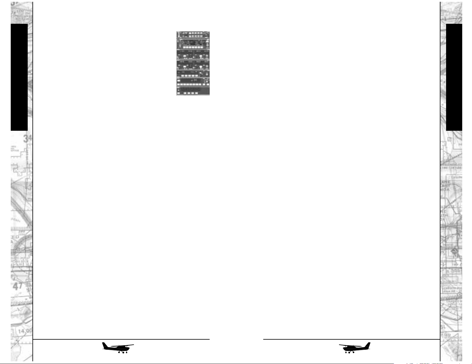
Simulation
Simulation
Simulation Controls
Cameras
Real-world pilots are only able to see from one vantage
point, their seat. While the main point of this simulation is to put
you in that position, you have even more power with Fly’s alternate camera views. These cameras (including your cockpit view)
offer almost infinite control over your viewing position.
Experiment with these cameras and use them in conjunction with
windows (see below) to find precisely the view and layout that
pleases you.
General Camera Control
Cycle Thru Cameras (i.e., Cockpit, Spot, Fly By, etc.) . . . . . . . C
Cockpit Toggle . . . . . . . . . . . . . . . . . . . . . . . . . . . . . . Shift + C
Moving the Camera
Some of the cameras can be moved and zoomed as you see fit.
Zoom Camera In . . . . . . . . . . . . . . . . . . . . . . . . . . Control + =
Zoom Camera In Fast . . . . . . . . . . . . . . . . . . . . . . . . . Shift + =
Zoom Camera Out . . . . . . . . . . . . . . . . . . . . . . . . . Control + -
Zoom Camera Out Fast . . . . . . . . . . . . . . . . . . . . . . . . Shift + -
Pan Camera Left . . . . . . . . . . . . . . . . . . . . Control + Left Arrow
Pan Camera Right. . . . . . . . . . . . . . . . . . Control + Right Arrow
Pan Camera Up. . . . . . . . . . . . . . . . . . . . . Control + Up Arrow
Pan Camera Down . . . . . . . . . . . . . . . . Control + Down Arrow
Camera Hot Key Definition
If you are particularly fond of a certain camera angle, you
can save it to a hot key for instant access. Simply establish the
camera position you want and define the position by pressing
Shift and any of F1 through F8. You can then press only the recall
key (F1 through F8) to instantly jump to that position.
Define Camera 1. . . . . . . . . . . . . . . . . . . . . . . . . . . . Shift + F1
Define Camera 2. . . . . . . . . . . . . . . . . . . . . . . . . . . . Shift + F2
Define Camera 3. . . . . . . . . . . . . . . . . . . . . . . . . . . . Shift + F3
Define Camera 4. . . . . . . . . . . . . . . . . . . . . . . . . . . . Shift + F4
Define Camera 5. . . . . . . . . . . . . . . . . . . . . . . . . . . . Shift + F5
Define Camera 6. . . . . . . . . . . . . . . . . . . . . . . . . . . . Shift + F6
Define Camera 7. . . . . . . . . . . . . . . . . . . . . . . . . . . . Shift + F7
Define Camera 8. . . . . . . . . . . . . . . . . . . . . . . . . . . . Shift + F8
Avionics Controls
Radios
A number of radios are available to assist you
in navigation and communication, including ADF,
COM, NAV, GPS, and transponder radios. For
details on the operation of these devices, see Radio
Flyer in the Flight Instruction section.
Tuning: As with all cockpit dials, you can point
at the dials with your mouse pointer and turn
them left and right with a Left-Click and RightClick (Windows) or a Click and Control-Click (MacOS). You
can also click directly on the LED numbers on the radio to
tune them up and down.
Autopilot: Autopilot allows you to relinquish the controls to
the tender mercies of your aircraft’s automated piloting system. Engage this system by toggling it on (disengage with the
same button). Once the system is engaged, you can instruct
the Autopilot to maintain either your altitude rate-of-change,
your heading, or both. Note that this is not a “real-world”
autopilot (that system is covered in the Pilot’s Manual) and is
available on all planes, regardless of whether the actual plane
is equipped with an autopilot.
Autopilot Toggle . . . . . . . . . . . . . . . . . . . . . . . . . . . . . . . . . . A
Autopilot Altitude Hold . . . . . . . . . . . . . . . . . . . . . Control + A
Autopilot Heading Hold . . . . . . . . . . . . . . . . . . . . . . . Shift + A
Lights
Navigation Lights, Strobe, and Beacon Lights. . . . . . Control + L
Landing and Taxi Lights . . . . . . . . . . . . . . . . . . . . . . . . Shift + L
Panel Lights . . . . . . . . . . . . . . . . . . . . . . . . . . . . . . . . . . . . . . L
Turns on and off the instrument panel lights in planes where
illumination is not automatic. The default aircraft in Fly! all have
full-time running instrument panel lights that do not have to be
manually turned on (though primary aircraft power must be on).
You cannot turn lights off in these aircraft, but you can adjust them
through the various cockpit light controls available in the cockpit
panels.
45
44
Page 24

Simulation
Simulation
Air Traffic Control
In the real world, Air Traffic Control (ATC)
is available (and sometimes mandatory) to pilots
when flying in and around major air traffic areas,
and when outside weather conditions prevent
flying by visual reference (Visual Flight Rules, or ‘VFR’flight). ATC
assumes many responsibilities, the most important is to maintain
a safe level of separation between a plane and any surrounding
planes or terrain. When flying in Instrument Flight Rule (‘IFR’)
conditions where visibility may be restricted, it is mandatory that
the pilot be in constant communication with ATC.
Fly! offers you the ability to participate with ATC as you
choose. This is considered an advanced feature, and may be
skipped by beginning pilots if desired. Fly! supports the primary
centers of control for ATC: Clearance Delivery, Ground Control,
Tower, Departure Control, Arrival Control, and Center. Each of
these centers is responsible for a specific area of control for aircraft operations. In addition to establishing and maintaining communications with ATC throughout your flight, you may also hear
other computer controlled planes as they interact with ATC. This
can occur at any time if a computer aircraft is using an ATC service on the same radio frequency as you.
ATC services are not available at all airports. In some cases,
you may only have a subset of the ATC services available. In these
cases, it is normal for smaller airports to offer multiple ATC services through the same controller. For example, some airports may
have a dedicated frequency and controller for Clearance Delivery,
and one for Ground Control. Another airport may have a single
frequency that covers Clearance, Ground, and Tower. Regardless
of this, Fly! will allow you to choose the “service” you want, even
if these are tied to the same frequency. If an airport only offers
Unicom (which only provides basic airport information), then you
will not see any ATC services listed for the airport, and IFR
approaches and departures will not be possible from the airport.
Recall Hot Key
Activate Defined Camera 1. . . . . . . . . . . . . . . . . . . . . . . . . . F1
Activate Defined Camera 2. . . . . . . . . . . . . . . . . . . . . . . . . . F2
Activate Defined Camera 3. . . . . . . . . . . . . . . . . . . . . . . . . . F3
Activate Defined Camera 4. . . . . . . . . . . . . . . . . . . . . . . . . . F4
Activate Defined Camera 5. . . . . . . . . . . . . . . . . . . . . . . . . . F5
Activate Defined Camera 6. . . . . . . . . . . . . . . . . . . . . . . . . . F6
Activate Defined Camera 7. . . . . . . . . . . . . . . . . . . . . . . . . . F7
Activate Defined Camera 8. . . . . . . . . . . . . . . . . . . . . . . . . . F8
Window Controls
This collection of mini-windows is among your most useful
tools. Use them in conjunction with any of the simulation’s cameras to get the complete picture of your plane and the world
around you. Note that these windows can be resized and persist
in both size and position even between sessions.
Basic Operation: Generally, windows operate like any other window in your operating system. Open with the keystrokes listed
below, move around by grabbing the top or title bar of the window,
and close with either a click to the appropriate corner or a key combination.
Secondary Camera View. . . . . . . . . . . . . . . . . . . . . . . . . . . . W
Map View . . . . . . . . . . . . . . . . . . . . . . . . . . . . . . . . . . . . . . M
Vector Window . . . . . . . . . . . . . . . . . . . . . . . . . . . . . Shift + M
Axis Window. . . . . . . . . . . . . . . . . . . . . . . . . . . . . . . . . . . . . X
Mini Cockpit Window. . . . . . . . . . . . . . . . . . . . . . . . . Shift + X
GPS Window . . . . . . . . . . . . . . . . . . . . . . . . . . . . . . . . . . . . N
47
46
Page 25

Simulation
Simulation
Contact Ground Control to receive permission to taxi, as
well as directions to the active runway.
Once you reach the active runway for take-off, you will
transition to Tower to receive permission to enter the active runway and take off. Once you have taken off, Tower will pass you
to Departure Control to vector out of the airport’s airspace safely.
Once out of the airport airspace, Departure Control will
have you contact Center to track and assist your flight enroute. If
you are travelling across large geographic distances, you may be
asked to tune to other Center controllers along the way. Once you
near your final destination, Center will hand you off to Approach
Control to begin your final descent and entry into the arrival airport’s airspace.
Approach Control will give you “vectors” for your final
approach, which are a series of heading changes to safely route you
into the traffic pattern and prepare you for landing. Once the active
runway is clear, and you are the next aircraft in line to land,
Approach Control will pass you to Tower for final clearance to land.
Once Tower is contacted, you will be given final clearance
and can make your approach. Once you land, you should clear
the active runway as soon as safely possible.
Once you are safely on the ground and at a full stop, you
will contact Ground Control to help guide you back to the terminal area of the airport. Once you have reached your destination
and have engines off, you can contact Clearance Delivery to close
your flight plan.
ATC On/Off Toggle . . . . . . . . . . . . . . . . . . . . . . . . . . . Shift + `
ATC Menu . . . . . . . . . . . . . . . . . . . . . . . . . . . . . . . . . . . . . . . `
ATC Response #1 . . . . . . . . . . . . . . . . . . . . . . . . . . . . . . . . . 1
ATC Response #2 . . . . . . . . . . . . . . . . . . . . . . . . . . . . . . . . . 2
ATC Response #3 . . . . . . . . . . . . . . . . . . . . . . . . . . . . . . . . . 3
ATC Response #4 . . . . . . . . . . . . . . . . . . . . . . . . . . . . . . . . . 4
ATC Response #5 . . . . . . . . . . . . . . . . . . . . . . . . . . . . . . . . . 5
ATC Response #6 . . . . . . . . . . . . . . . . . . . . . . . . . . . . . . . . . 6
ATC Response #7 . . . . . . . . . . . . . . . . . . . . . . . . . . . . . . . . . 7
ATC Response #8 . . . . . . . . . . . . . . . . . . . . . . . . . . . . . . . . . 8
ATC Response #9 . . . . . . . . . . . . . . . . . . . . . . . . . . . . . . . . . 9
ATC Response #10. . . . . . . . . . . . . . . . . . . . . . . . . . . . . . . . . 0
You may activate ATC at any time, regardless of whether you
created a flight plan or if you started the simulation from the Fly
Now view. To communicate with ATC, press the ATC key (`). You
will be prompted with a list of ATC services to communicate with.
If your COM radio is already tuned to a valid ATC service, Fly!
will bypass this selection window and proceed to your request.
Once you select the ATC service to communicate with, a
window will appear with the available requests or responses you
can make to ATC. If your COM radio was not already tuned to the
ATC service, it will be auto-tuned for you. Press the ‘1’ through ‘0’
key to select the request or response you wish to make. The ATC
system will react as appropriate, and will give you verbal instructions on how to proceed.
All ATC communications are echoed to a scrolling text display at the top of your screen. If you have multiple radios tuned
to multiple services, you will see a separate text display for each
ATC communication you receive. You can turn off the audio portion of ATC communications through the Sound options dialog
(see p. 12)
Remember that your radio is your “life-line” to ATC. If you
tune your radio away from ATC, or turn off the COM radio audio
through the audio panel of the aircraft, you will be blissfully
unaware of any demands ATC is making of you. In real life, this
could result in serious fines or suspension of your license!
Fortunately in Fly! you can choose to ignore ATC if you wish – just
remember that there are other planes in the air that are assuming
you will follow ATC’s instructions.
The normal “steps” of participating with ATC are as follows:
Tune your COM radio to the ATIS frequency for the airport
you are departing. The ATIS frequency is shown on the sectional
map, and can also be obtained by double-clicking the airport in
the Vector Map window or by using the “Range Finder” feature
(see p. 52). ATIS is an automated weather observation system, and
you will be required to have this information before contacting
Clearance Delivery.
Contact Clearance Delivery. If you created a flight plan in
the Flight Planner, you will open your flight plan with Clearance
Delivery at this time. Clearance Delivery will also verify that you
have the latest ATIS information.
49
48
Page 26

Simulation
Simulation
Distance Compression
You can shorten long flights by activating the Distance
Compression feature. When this feature is armed, it effectively
shrinks the ground distance between where you are and where
you want to go allowing you to cover more ground in the same
amount of time. Here’s what distance compression does not do: it
does not speed up time, it does not change the control of your
plane or the physics acting upon it. Effectively, it shrinks the
world.
Each increase in Distance Compression halves the normal
distance. This continues exponentially up to a factor of 1/64th.
Distance can not be expanded beyond a 1:1 ratio.
Increase Distance Compression . . . . . . . . . . . . . . . . . . . . . . . D
Decrease Distance Compression. . . . . . . . . . . . . . . . . Shift + D
Instant Replay
Any time you wish to review your most recent actions in
flight, bring up the Instant Replay tool. Doing so will pause the
simulation and open a window containing a strip of buttons like
the controls on a VCR. You can Play, Rewind, Fast Forward, or
Reverse Play through the last few minutes of flight (based on your
frame rate and available memory).
If you press the Play or Reverse Play buttons repeatedly, the
rate of play is doubled (up to 8x) each time you press the button.
You can slow the replay back to normal speed by pressing stop
and hitting play once.
A NOTE and a WARNING: Instant Replay is not only a VCR,
it’s a time machine. When you go back in time through its recording of your flight, you are actually transporting the simulation
back to that point in time (though any on-screen time display will
not change). In other words, were you to run the instant replay
back one minute and then deactivate instant replay, you would
regain control of your aircraft at that point. This can be useful to
re-attempt a failed or missed approach. If you wish to resume your
flight from where you were, be sure to fast forward to the latest
end of Instant Replay and then exit.
Exiting the Instant Replay window resets the replay buffer
and begins a new recording.
Activate Instant Replay . . . . . . . . . . . . . . . . . . . . . . . . . . . . . . I
Slew Controls
Slew Mode allows you to suspend the
simulation and manually place the aircraft
anywhere and in any position you like. To
activate Slew Mode, press S. Once in Slew
Mode, the keys listed below will control the
position of the aircraft. Movement in Slew Mode is continuous
and cumulative, meaning that the longer you hold a Slew directional key, the faster your craft will move. When you reach the
position you want, press Slew Stop to freeze.
Slew Mode . . . . . . . . . . . . . . . . . . . . . . . . . . . . . . . . . . . . . . S
Slew Stop . . . . . . . . . . . . . . . . . . . . . . . . . . . . . . . . . . . Num 5
Slew Up . . . . . . . . . . . . . . . . . . . . . . . . . . . . . . . . . . . . . . . . Q
Slew Down . . . . . . . . . . . . . . . . . . . . . . . . . . . . . . . . . . . . . . A
Slew Left . . . . . . . . . . . . . . . . . . . . . . . . . . . . . . . . . Left Arrow
Slew Right . . . . . . . . . . . . . . . . . . . . . . . . . . . . . . . Right Arrow
Slew Backward . . . . . . . . . . . . . . . . . . . . . . . . . . Down Arrow
Slew Forward . . . . . . . . . . . . . . . . . . . . . . . . . . . . . . Up Arrow
Pitch Up . . . . . . . . . . . . . . . . . . . . . . . . . . . . . . . . . . . . . Insert
Pitch Down . . . . . . . . . . . . . . . . . . . . . . . . . . . . . . . . . . Delete
Bank Left . . . . . . . . . . . . . . . . . . . . . . . . . . . . . . . . . . . . Home
Bank Right . . . . . . . . . . . . . . . . . . . . . . . . . . . . . . . . . . . PgUp
Rotate Left . . . . . . . . . . . . . . . . . . . . . . . . . . . . . . . . . . . . . End
Rotate Right . . . . . . . . . . . . . . . . . . . . . . . . . . . . . . . . . . PgDn
Changing Time of Day
You may freely change the time of day in Fly! while in-flight.
Using these keys adjust the time forward or backward by 30 minutes at a time. Note that this does not affect the simulation – your
plane will move at its current speed and continue to fly as expected. Fly! accurately computes the position of the sun, moon
(including moon phases) and stars based on the exact month, day,
year, and time you have selected and your location on the Earth.
Changing time of day will also affect the position and perspective
of any ground shadows being cast by aircraft or ground structures.
Time Forward . . . . . . . . . . . . . . . . . . . . . . . . . . . . . . . . . . . . T
Time Backward. . . . . . . . . . . . . . . . . . . . . . . . . . . . . . Shift + T
51
50
Page 27
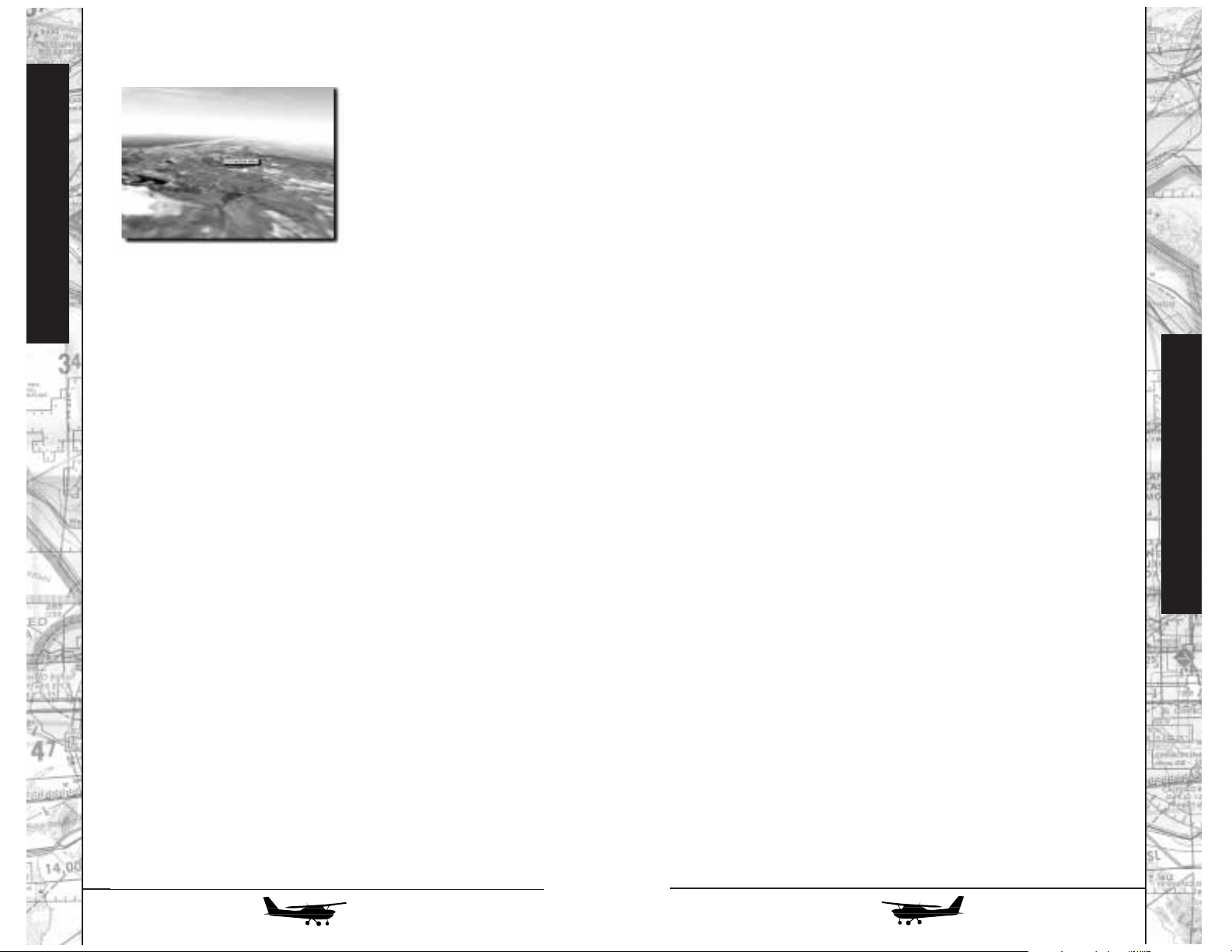
Range Finder Feature
Simulation
ground, the sky, or in the air and you will see a label identifying
the object and calculating the distance to it.
While in any camera
mode, you can use the Range
Finder Feature to identify
important structures and landmarks within your field of
view.
Once you activate the
Range finder, you may point
at any object you see on the
Flight Instruction
To Dianne - I’m really married to you, not this
manual.
You can point to almost anything with this tool. Pointing at
a building or structure will display the height of the structure, your
current clearance over the structure (to make sure you can clear it
from a distance), and the range to the structure. Pointing at an airport or VOR will show you their name and range. You can double-click on an airport to receive an Airport Information window,
which displays runway, localizer, and ATC frequency information.
You can double-click on a VOR to receive information about its
operating range and frequency. If you are feeling really adventurous, you can find the range to the sun and the moon, or the catalog names of stars in the sky!
Activate Range Finder . . . . . . . . . . . . . . . . . . . . . . . . . . . . . . . /
Web Sites of Interest
http://www.iflytri.com
http://www.terminalreality.com
http://www.godgames.com
Airplane Manufacturers
Cessna C172R:
http://www.cessna.textron.com/
Piper Malibu Mirage and Navajo:
Author Bio
Peter Lert started flying in sailplanes while a high school student in Switzerland. In the subsequent 35 years, he's amassed
some 15,000 flight hours as well as obtaining Airline Transport
Pilot and Certified Flight Instructor licenses for aircraft ranging
from balloons to jets.
He has worked as an experimental test pilot, aviation journalist, and was Senior Scriptwriter for the Interactive Systems
Division of FlightSafety International, the world's largest private
provider of full-scale flight simulator training. At present, he lives
in the mountains of southwest Colorado and is chief pilot of two
multi-engine flight operations (one corporate, one charter).
Flight Instruction
http://www.newpiper.com/
Raytheon Beech Super King Air B200 and Hawker 800XP:
http://www.raytheon.com/rac/
52
53
53
Page 28

55
Flight Instruction
54
Flight Instruction
Fly! - Chapter 1
Those features, though, aren’t what we’ll address in this
manual. With an interface as realistic as FLY!’s, you don’t need
“yet another computer manual” (and, for those of you who want
to learn about keyboard shortcuts and other “simulator only” features, those total nerds
my esteemed colleagues over at the computer side of the house have provided an excellent one). Instead,
what you’re holding is almost entirely a flight manual, written as
though I were actually instructing you in the airplane (as I do in
real life). In fact, I’ll make almost no mention of keyboard or even
mouse commands unless absolutely necessary; since operation of
the program is so simple and instinctive, I’ll just say something like
“use the prop control to increase the RPM” or “tune the nav radio
to 118.5 mHz,” with the assumption that you’ll simply reach out
and do it.
This means that it’s very worthwhile for you to take a look
through the Simulation Interface (see page 4) now to make sure
you’re up to speed on the basic techniques. They’re all simple and
self-consistent: you use the same moves to “grab” and operate any
switch, knob, or handle on the panel, regardless of its function (or,
for that matter, in which airplane it’s installed). Again, this is merely realism - in the real airplane, your hand would work the same
way all the time.
A MATTER OF CONTROL:
FLY! supports just about any input device currently available,
including both conventional and force-feedback joysticks. That
being said, however, I’d personally suggest that you’ll get the most
out of FLY! if you use a control yoke: all five of the airplanes modeled in this release have yokes, rather than sticks, in their actual
cockpits. Similarly, for single-engine airplanes, a simple throttle (or
the one provided on most yokes) will suffice; those fancy multifunction ones, studded with so many buttons and switches they
look like a chunk sawed out of a bassoon, are more suited to military flight simulations, and have no counterpart in civil aircraft at
this time. (For multi-engine airplanes you’ll most likely be grabbing the screen throttles with your mouse.) Rudder pedals are an
excellent idea, particularly if you’re planning serious engine-failure work in the multiengine birds.
Fly! - Chapter 1
INTRODUCTION
Welcome to the start of what we’re sure will be an exciting,
entertaining, and instructive experience. FLY! has been designed
to replicate the sights and sounds of flying some of general aviation’s best-known aircraft with unparalleled realism. It goes much
farther than that, however. The handling and aerodynamic
responses of all the airplanes available have been mathematically
duplicated, or “modeled,” with a level of accuracy that approaches (and, in many cases, surpasses) that of full-scale airline and military flight simulation systems. Extremely detailed terrain rendering, based on actual satellite imagery and topographic data, makes
the outside view as realistic as possible, while the combination of
photorealistic instrument panels and actual working panel controls (i.e., you can simply “grab” the appropriate switch or knob
with your mouse) completes the picture and puts you right in the
pilot’s seat. (After all - how many real airplanes are controlled from
keyboards?)
Want even more realism? FLY! has a very sophisticated
weather “engine” to provide weather effects from innocuous fairweather clouds to blinding fog, or the firehose rain of a thunderstorm.
Page 29

57
Flight Instruction
56
Flight Instruction
Fly! - Chapter 1
From there, we’ll move on into the fascinating world of multiengine airplanes. We’ll start with a medium piston-powered
twin, the Piper Navajo Chieftain. For years a mainstay of both corporate and, in particular, commuter flying, the old “NavaHog” is
the airplane on which many of the current generation of airline
pilots got their “heavy iron” start. Next will come the classic Beech
Super King Air 200 - the epitome of the corporate turboprop, and
one that remains not only in production, but in service in both
executive and commuter versions worldwide.
Finally, we'll come to a classic midsize business jet: the
Raytheon Hawker 800XP. Based on one of the earliest business jet
designs, this enduring classic has developed to a luxurious modern corporate cruiser with transcontinental (or even transoceanic)
capabilities and a thoroughly up-to-date suite of avionics, including the latest electronic cockpit displays. It's in this aircraft that
you'll be introduced to the special worlds of swept-wing aerodynamics and high-speed, high-altitude flight.
Here, then, is FLY! We’re sure it’ll provide you with hours of
far more than just entertainment…and now, if you’ll grab your
flight cases and move into the classroom at the back of the hangar,
we’ll begin our preflight briefing…
Hawker 800XP
Fly! - Chapter 1
TAKING IT IN SEQUENCE:
We’ve laid this flight manual out in a logical sequence to fit
the needs of just about anyone, whether you’re a first-time novice
or an experienced pilot (of either flight simulation programs or
actual airplanes). If you’re starting from scratch, you’ll find your
enjoyment of the program greatly enhanced if you take the time to
read the chapters on fundamentals of flight and cockpit basics it’ll make your subsequent flights much easier. If you have any
experience, either real-world or simulated in any of the planes presented, by all means jump right in. Indeed, there’s no reason you
shouldn’t try your hand at, say, the Hawker 800XP jet, even if all
you’ve ever flown has been a single-engine trainer - just don’t
expect to do any better than you would in a similar real-life situation! Sure, you may survive and even have fun - but you’ll be using
FLY! more as a game than as the extremely sophisticated flight simulation system it really is. (Of course, all of us like to just play
sometimes…and there’s nothing wrong with that.)
The airplanes we’ve chosen are presented in the same progression you’d encounter if you were actually learning to fly and
starting a career that could culminate in the airlines or at the pinnacle of corporate aviation. We’ll start out with a basic light single, the Cessna 172R Skyhawk - the airplane, in fact, in which tens
of thousands of Americans have earned their Private Pilot license.
From there, we’ll move on to the Piper Malibu Mirage, a heavy
single (or what the FAA calls a “complex high-performance aircraft”). With its pressurized cabin, turbocharged engine, and
advanced avionics, the Mirage is one of the most sophisticated
piston-powered single-engine airplanes ever manufactured. If the
Skyhawk is “the Plymouth of general aviation,” the Mirage is its
Lexus or Mercedes Benz.
Yoke vs. Stick
Page 30

59
Flight Instruction
58
Flight Instruction
THE BALANCE OF FORCES
Most aeronautics texts teach
that there are four forces that act on
an airplane in flight, and that they
show up in two opposing pairs. One
pair is weight, which is pretty obvious, and lift, the force exerted by
the wings in holding the airplane up
in the air (you’ll find out in a
moment that lift does a lot more than
that). The other pair is thrust, the
force that pulls or pushes the airplane forward through the air, and
which is usually provided by some kind of engine (but not always look at gliders!), and drag, the opposing force that tries to hold it
back. (Actually, all aircraft are supported by a fifth force, invisible
but all-pervasive, called money - and that’s the reason we need
flight simulators like FLY!)
As long as we’re flying along straight and level, and at a constant speed, all four of these forces are in balance. The weight of
the airplane is exactly counteracted by the lift of the wing, so it
goes neither up nor down. Its drag, caused partly by the wing’s
efforts to keep everything aloft and partly by the effort needed to
push the whole airplane forward through the air, is exactly counteracted by the thrust of the powerplant, so it neither speeds up nor
slows down. As soon as we try anything even the slightest bit
fancy, though - say, a turn, climb, or descent, or, worse yet, some
combination of these - things start getting a bit more complex.
The Four Forces
Lift
Thrust
Weight
Drag
Force of Money
FUNDAMENTALS OF
AERODYNAMICS
There are a number of different ways to go about learning to
fly. One - we might call it “the old school”—is to just sit down in
an airplane with an instructor and start flying. Another, however,
can make the whole experience much more rewarding: learning a
little, before you start flying, about what’s really going on, what
really makes your aircraft fly and behave the way it does. That’s
the way I try to start out my real-life flying students; and that’s what
we’re going to do here.
THE WING’S THE THING
All five of the aircraft presented in this release of FLY! have
something in common: they’re all fixed-wing airplanes. By this, I
don’t mean that they’ve been broken and repaired, but rather that
their wings stay decently in one place, rather than the unseemly
flailing about we see in rotorcraft. We could say that the wing is
really the most important part of any airplane; all the other bits,
like powerplants and control surfaces, are really there to aid the
wing in fulfilling its purpose: providing lift.
What’s lift? It’s simply the force generated by the wing as it
deflects the air through which it’s moving.
Rotorcraft
Page 31

61
Flight Instruction
60
Flight Instruction
A MATTER OF CONTROL:
The lift produced by an airplane’s wing does a lot more than
just hold it up in the air. A car is steered by the side forces generated by its tires against the pavement. The airplane, though, has
nothing to push against but air, and nothing to push with but its
wing. To get the airplane to move in the direction you want - and
that includes up and down as well as to the side in turns - you
have to direct the wing’s lift in the desired direction and/or change
its amount. This is where the flight controls come in.
You may be using a joystick or a yoke with FLY!, and you
may or may not have rudder pedals, but the basic principle of all
these controls is the same: you’re going to use them to point the
airplane in the desired direction, then use the lift forces generated
by the wing to actually determine where you go. As long as the air
isn’t too bumpy, just about any airplane will fly along quite nicely, continuing in whatever direction it’s pointed without much
attention required from the pilot, as long as all the controls are
centered. (A well-aligned car on a straight road is in a similar situation.) Where the difference between airplanes and cars becomes
clear, however, is how the controls are used when you want to
make a change.
If you want to turn a car - say, to follow a curve in the road
- you’d turn the steering wheel until the car was turning at the rate
you wanted, then hold it in that position until you’d completed the
turn. In the airplane, it’s quite different. To start a turn, you’ll move
your yoke or joystick to start banking in the desired direction - but
as long as you hold the controls in that direction, the airplane will
continue to increase its bank angle, steeper and steeper. (In fact, if
you held the controls into a turn long enough, the airplane would
perform a complete roll, something not recommended in any of
the five real-world airplanes currently simulated in FLY!).
Instead, move your controls only until you’ve reached the
desired bank angle, then return them to the center. The airplane
will tend to hold that bank angle and continue around the turn,
pretty much on its own. When you want to roll out to level flight,
you’ll actually have to move the controls the other way until the
wings are level once again. Similarly, if you want to climb, pull the
stick or yoke back gently until the nose rises to the angle you want;
then return it to, or near, the center to hold that position. To level
off from a climb, ease the controls gently forward until the nose is
back down where you want it, then re-center them once again.
LIFT IS WHERE YOU FIND POINT IT:
The lift a wing produces is, for all practical purposes, at right
angles to its surface. Bank the airplane into a turn, for example,
and the lift banks with it; instead of lifting straight up, the wing is
now also pulling the airplane toward the inside of the turn. (In fact,
that’s what makes the airplane turn in the first place.) Of course,
this also means that there’s less lift available to counteract the pull
of gravity, so unless we take appropriate measures, the airplane
will tend to sink a bit when it’s turning.
IT’S ALL IN THE ANGLES:
To deal with this, as well as with many
other situations in flight, we have to control the
amount of lift the wing produces. In a turn, for
example, we have to increase the amount of lift
so there’s enough available both to hold the airplane up and to pull it into the turn. To do this,
we’ll increase something called angle of attack,
and this is a concept important enough to merit
a few paragraphs in its own right.
The amount of lift produced by any wing is
dependent on two major factors: the speed at
which it moves through the air, and the angle between the airflow and the wing’s chord line, an
imaginary line between the centers of its leading
and trailing edges. We’ve probably all performed
(and been yelled at for) the classic basic experiment of aerodynamics: sticking our hands out of
the window of a moving car. Tilt the front of your
hand up (increasing the angle of attack), and
your arm rises; tilt it down, and it sinks. This can
occupy simple minds for many miles.
What may have been a bit less obvious
was that it took a lot more tilt to hold the weight
of your arm at lower speeds than at high ones.
Indeed, once the speed got low enough - usually right before you got dropped off at school - no
amount of tilting would be sufficient, and your
arm would drop painfully onto the doorframe.
You’d reached the stalling speed of your wing er, arm. We’ll discuss stalls in considerably more
detail when we start flying the Cessna 172.
Normal Lift
Increasing Angle
of Attack
Stalling
Chord Line runs
thru center
of wing
Page 32
63
Flight Instruction
62
Flight Instruction
ADVANCED AERONAUTICS:
A CLOSER LOOK AT LIFT
In the main part of this chapter, we’ve explained that lift not
only supports, but also steers, an airplane. A little more detail
about how lift is produced (and what happens if and when that
production quits!) can be very valuable - and it’ll increase your
understanding of all the airplanes simulated in FLY!
IT’S ALL IN THE CURVES:
We’ve already learned that to hold the airplane up, the wing
has to push down against the air with an equal force...but if we
look closely, it’s not really “pushing.” In fact, that’s the error made
by the first would-be flyers, who tried to use simple flat surfaces boards!—as wings. It wasn’t until pioneers like Lilienthal and the
Wright brothers examined the wings of birds that they realized that
the secret was in their curved shapes. Actually, Leonardo da Vinci
had figured that one out four hundred years earlier...but he was a
theorist rather than an experimenter.
It wasn’t long after da Vinci that another European, Daniel
Bernoulli, discovered that the faster a fluid moves (whether it’s air
or water), the lower its pressure will be. Here’s a simple experiment: take a sheet of typing paper and hold it, by its two top corners, just below your mouth. Now blow gently over the top of the
paper. You’ll notice that it floats up to the horizontal, even though
you’re blowing across the top rather than underneath it. Why? Because the fast-moving air over the top of the paper is at low pressure compared to the air underneath.
A wing works the same way: it’s not so much “pushing”
down the air below it as it’s “pulling” on the air above its upper
surface. This is why its curved surface is so important. The distance from the front of the wing to the rear (from its leading
edge to its trailing edge) is longer around the curved top than
along the relatively straight bottom. Air flowing around the
wing has to speed up over the top, thus creating lower pressure
and generating lift.
WHAT DO THE CONTROLS DO?
All fixed-wing airplanes have three primary flight controls:
ailerons, elevator, and rudder.
The ailerons are what
make the airplane bank left
and right. They’re small flaps
hinged to the rear of the wing,
near the tips (in fact, their
name means “little wings” in French), and they work in opposition: when one goes up, the other goes down. They’re connected
to the cockpit controls so that they’re operated by sideways (leftright) movement of the stick or yoke.
The elevator is the movable portion of the horizontal tail,
and its name is something of a misnomer: although it indirectly
can affect the altitude at which an airplane flies, what it controls
directly (and very effectively) is nothing more than our old friend
angle of attack. It’s operated by forward-backward movement of
the stick or yoke: pull the control back toward you, and angle of
attack increases; push it away, and angle of attack decreases.
Note that I purposely haven’t said “the nose goes up,” “the
airplane gets slower,” or anything similar, since that depends
entirely on the initial position, or attitude, of the airplane. For
example, in the unlikely event of your being upside down, pulling
the controls would bring the nose down toward the ground while
increasing the airspeed alarmingly. A considerably more common
situation would be a steeply-banked turn; pulling the stick or yoke
would tighten the turn, but wouldn’t have much direct effect on
your altitude or speed (at least at first).
Finally, the rudder is the movable portion of the vertical tail. A
common misconception is that this is what turns the airplane. In
fact, it’s the lift from the banked wing that makes the turn; the function of the rudder is mainly to ensure that the airplane is pointed the
same way it’s going, rather like the feathers on an arrow. In an actual airplane, it’s controlled by the foot pedals. Don’t worry too much
if you don’t have a set of rudder pedals for FLY!; the program can be
configured to handle rudder chores automatically. In fast, high-performance airplanes, the rudder isn’t as important as in slower ones.
Most jets, such as the Hawker 800XP in FLY!, are flown “feet on the
floor” except during takeoff, landing, or engine failures.
Rudder
Aileron
Elevator
Page 33

65
Flight Instruction
64
Flight Instruction
On the other hand, if it’s pointed
even slightly downward, as it would
be during a descent, its aero force
points slightly forward, pulling the
airplane along (fig. 4). This is
how gliders (sailplanes) can keep
moving, even though they don’t
have engines: they’re always
descending through the air. How
do they stay up all day? By finding
areas where the air is rising faster than
the glider descends... just like when you
used to get yelled at for playing on the
escalators at the mall.
The amount of lift a wing can produce depends on four
things. One is more or less constant: the design of the wing and its
airfoil. Generally, a thick, highly curved wing produces lots of lift
at low speeds, making it ideal for slow, light aircraft. A thin wing
produces less lift, but is more efficient at high speeds; you’ll find it
on jets. (How do jets manage to take off and land at reasonably
low speeds? By changing the shape of their wings with various
flaps, slats, and similar movable bits and pieces.)
WHAT’S YOUR ANGLE?
Two more variables can change the amount of lift a wing
produces: the speed at which the wing is moving through the air,
and its angle of attack - the angle between the wing’s chord line
and the oncoming air (also called the relative wind). At high
speed, it only takes a little angle of attack to generate enough lift
to support the airplane. The slower we fly, the more angle of attack is necessary to generate the same amount of lift. Next time
you’re near an airport, watch the airliners coming in. Even though
they’re descending as they near the runway, they’re flying along
slightly nose-high - at their low approach speeds, it takes a lot of
angle of attack to provide enough lift. As they descend the last few
feet, their noses rise even more. This maneuver is called the landing flare. The pilot is trying to make the touchdown as soft as possible. As speed bleeds off over the runway, it takes even more
angle of attack to reduce the rate of descent and avoid one of those
“take that, La Guardia” arrivals.
Figure 4
There’s another reason the
curve is important as well. Look at
these two pictures. The first (fig.
1) shows a flat surface angled to
the air, as tried by the first (unsuccessful) experimenters.
You’ll see that it produces a
very limited amount of lift from
the “push” on its bottom surface...but the airflow over the top
“trips,” or separates, as soon as it gets
past the sharp leading edge, and rather
than speeding up over the top it just
swirls in useless turbulence. Not only does it not create any lift, it
also causes a great deal of drag.
In the second picture (fig. 2), we’re
looking at a cross-section of a typical
wing, or airfoil. Because of its
curved surface, the air can flow
smoothly over the top surface. This
is where most of the lift is produced. Notice, too, that we’ve
drawn a line from the center of the
leading edge to the trailing edge.
Aeronautical engineers call this the
chord line of the wing...and what’s important about it is that any aerodynamic
force the wing produces
will always act exactly at right angles to
the chord line. This means that if the
wing is tilted up (as it is even in
level flight, if only by a small
amount), its lift points very slightly
backward. If it weren’t for the
thrust of the engine, the airplane
would slow down (fig. 3).
Figure 1
Figure 3
Figure 2
Page 34

TOO MUCH OF A GOOD THING:
Unfortunately, we can’t just go on
increasing angle of attack forever as
speed bleeds off to zero; if we
could, we’d have no need for helicopters. Instead, once the angle
of attach reaches a certain point
(called critical angle of attack), the
air can no longer make the curve
around the leading edge and over
the top of the wing. Instead, the flow
separates, becoming turbulent over the
top of the wing (fig. 5). Notice how similar this is to the flat plate in figure 1? That’s
right: when this happens, most of the lift disappears, and the wing
is stalled. At this point the wing has, for all practical purposes, “quit
flying;” gravity reasserts itself, and the airplane begins to drop.
Sounds serious, doesn’t it? It is, of course...but hardly fatal.
All that’s necessary to recover from the stall is to reduce the angle
of attack below the critical level by easing forward on the controls.
The airflow promptly reattaches itself, and the wing resumes its job
of producing lift. You’ll practice stalls, and stall recoveries, in all
the airplanes in FLY! A stall isn’t even a particularly dangerous or
unusual situation. Until the last years of World War II, almost all
airplanes were “taildraggers,” with two large main landing gear
Flight Instruction
and a small caster under the tail. These airplanes sit on the ground
right at the critical angle of attack, and thus have to be fully stalled
for a “three point” landing. In fact, a perfect landing in a taildragger is actually a complete stall followed by an uncontrolled
crash...from an altitude of, say, half an inch!
Figure 5
IT’S ALL IN THE ANGLE:
There are two vital things to remember about stalls:
The most important one is that, while we may often talk
about an airplane’s “stalling speed,” that can be misleading.
Whether or not a wing will stall depends only on its angle of attack - and the stall can and will occur at any speed if the critical
angle of attack is exceeded. Wrap an airplane up into a steep turn,
so that centrifugal force adds to its apparent weight, and you’ll
have to increase the angle of attack to compensate. At some point,
you’ll have pulled all the way to the critical angle of attack, and
the wing will stall even though you’re flying well above the published stall speed. Don’t worry - these high-speed, or accelerated,
stalls are no more fearsome than the regular kind, and we’ll practice them together.
The “stall speed” published in an airplane’s specs only applies to a stall entered gently from straight and level flight. Most
airplane handbooks include a table that shows vividly how the
stall speed goes up at increasing angles of bank.
The other thing to remember is that, in aviation, the word
“stall” means only one thing: the condition in which the airflow
over the wing has separated, and lift has been impaired. It has
nothing to do with the engine quitting (nor, for that matter, with the
small enclosures used to confine farm animals). After all, even
gliders can stall with no engines at all!
Flight Instruction
Axes of Movement in an Airplane
Roll Pitch Yaw
66
Angles of Attack
67
Page 35

68
69
Cessna 172R –
Introduction and Tour
We’ve spent enough time looking at theory in the last couple of chapters. Let’s start flying - and our steed for these first introductory lessons will be the same airplane that’s probably taught
more Americans to fly than any other: Cessna’s immortal 172.
A LITTLE HISTORY
If the Douglas DC-3 is sometimes characterized as “the
plane that taught the world to fly,” then the Cessna 172 would
have to be “the plane that made Americans pilots.” First introduced in 1956 (when it sold for all of $8750 brand new), it was
aimed squarely at the prosperous postwar middle class. As such, it
was designed to be uniquely easy to fly, featuring “Land-o-Matic”
tricycle gear (no, really - advertising copywriters in the ‘50s were
something else), “Para-Lift” flaps, and car-like doors on each side.
Contemporary ads featured all-American families flying off for
wholesome vacations; the dads almost invariably decked out in
Ward Cleaver-style fedoras.
“But wait - there’s more!” Two years ago, the 172 went back
into production at Cessna’s brand-new single-engine plant at
Independence, Kansas. By now it may well be the most produced
plane in history, eclipsing even Germany’s Me-109 fighter and
Russia’s IL-2 Shturmovik attack plane. It’s a little hard to be exact
- record keeping got a little spotty in the final months of World
War II! With its fuel-injected engine and fancy instrumentation,
the new 172R (the model included in FLY!) may seem a far cry
from that first 1956 model...but it’s still essentially the same
benign and efficient “Plymouth of the skies,” and its handling and
performance are still as amiable as ever. Alas, a new one, well
equipped, may leave you just enough for an airport cheeseburger...from a $150,000 check.
Flight Instruction
Flight Instruction
Cessna’s Skyhawk
“The Plymouth of the Skies”
Page 36

70
71
A COCKPIT TOUR
Let’s settle into the left seat and take a look around. You’ll
notice right away that just about everything is grouped on the left
or pilot’s side of the panel; unless the airplane has a lot of optional equipment installed, the copilot’s side is mostly blank.
Directly in front of the pilot, at the top of the panel, are the
six primary flight instruments, arranged in two rows of three. These
are sometimes called “the sacred six,” and we’ll examine them in
more detail in just a moment. They’re mounted on a separate section of the panel, which is shock-mounted - i.e. it “floats” in rubber mounts - primarily to protect the delicate gyro instruments
from vibration.
To the left of the flight instrument panel, a cluster of four
smaller gauges monitors the health of the engine and aircraft systems; the single one above them is a digital clock. Just below the
bottom right of the six primary instruments is another full-size
gauge; this is the tachometer, and in this airplane, it’s the primary
reference instrument for setting power.
To the right of the main flight instrument panel, three full-size
instruments in a vertical row display navigational information. To
the right of these, stacked vertically, are the airplane’s communication and navigation radios.
There’s some important stuff along the bottom of the panel,
too. At the lower left are the ignition key - we won’t get very far without that one - and switches for the airplane’s electrical system and
accessories such as internal and external lights. At bottom center are
the plunger-style throttle and fuel mixture controls; to the right of
them, the appropriately flap-shaped handle for the wing flaps.
Finally, the vertical part of the panel, going down to the floor,
has some important controls of its own. At its left, you’ll see a
large, vertically mounted knurled wheel. This is the airplane’s trim
control, and you’ll find yourself using it often. Below that is a red
fuel shutoff knob, which would normally be pulled only in case of
fire or fuel leak. Further down, just above the floor, is the fuel
selector which governs whether fuel will be drawn from the left
wing, the right wing...or both at once, the position in which it’s
usually kept.
Flight Instruction
Flight Instruction
Digital Clock and Timer
Airspeed Indicator
Attitude Gyro (Artificial Horizon)
Altimeter
CDI (NAV1, NAV2)
Fuel Flow/EGT
Fuel Quantity
Oil Temp/Oil Press
VAC/AMPS
Magnetos
Alt/BAT Switches
Directional
Gyro
Fuel Beacon Landing Taxi NAV Strobe Pitot
Pump Light Light Light Light Light Heat
Master Avionics
Switch
Turn Coordinator
Flaps
Mixture
Throttle
Alt Static Air
Vertical
Speed Indicator
ELT (Emergency Locator
Transmitter)
Tachometer
ADF
Cessna 172R Cockpit
Audio Panel
GPS Panel
NAVCOMM1
NAVCOMM2
Auto Direction Finder
Transponder
Auto Pilot
Page 37

72
73
You’ll notice some colored markings on the ASI. The green
arc is the normal operating range; its lower edge is the speed at
which the airplane will stall with flaps retracted. The beginning of
the white arc, at a somewhat lower speed, is where the airplane
will stall with its flaps extended all the way; the top of the white
arc is the fastest you’re allowed to fly with them extended (anything faster will put too much stress on them). The yellow arc,
which begins at the top end of the green one, is a caution range it’s okay to fly there if the air is smooth, but if it’s bumpy, you risk
over-stressing the airplane. (In the 172, about the only way you’ll
even get into the yellow is if you’re coming downhill with a fair
amount of power on.)
Finally, at the top of the yellow arc, there’s a redline, called
the “never-exceed speed.” That’s exactly what they mean: fly faster
than that, and you’re a test pilot. Make an abrupt control movement above redline, or hit a good solid gust, and you could find
yourself literally “walking on air.”
THE AT TITUDE GYRO
At the center of the top row is the “other
single most important instrument,” certainly
the most important if you’re flying on instruments: the attitude gyro, often also called
the “artificial horizon.”
This is the instrument you’ll use to
control the airplane when you can’t see out
the windshield. Without gyro instruments, even
the most skilled pilot can’t tell if the airplane is flying straight or
turning, flying level, climbing, or descending, unless he or she can
see the real horizon out in front.
At the center of the attitude gyro is a little symbolic airplane,
which always remains in a fixed position. The rest of the instrument moves behind it. The blue portion represents the sky, the
black or brown portion the ground, with the division between
them showing the horizon. Thus, as you maneuver the actual airplane, you’ll see the horizon in the instrument move to show your
attitude, your position in space.
The scale at the top of the instrument reads actual bank
angle, with small marks every ten degrees up to 30 degrees, then
two more marks at 60 and 90 degrees.
INSTRUMENTS: THE “SACRED SIX”
Since you’ll be spending most of your time looking at the
six main flight instruments, we’ll cover each in detail. By the way,
this particular arrangement of them - two rows of three, with a specific location for each - is standard worldwide. You’ll find the
same arrangement in all the airplanes in FLY! that have conventional round instruments - and even the Hawker Jet, with its allelectronic display, presents its information in a similar order. The
information presented here is equally valid for all the rest of the
airplanes in FLY!, so feel free to refer back here if you have questions later on in your FLYing career.
THE AIRSPEED INDICATOR
At the top left of the flight instrument group is
what’s probably the single most important dial
in the whole airplane: the airspeed indicator,
often abbreviated ASI.
Functionally, it’s very simple: nothing
more than a pressure gauge, connected to a
small tube (the pitot - pronounced pee-toe -
tube) that’s mounted on the outside of the airplane, with its open end facing forward. The faster you fly, the
more air pressure is rammed into the pitot tube and indicated on
the ASI - which of course is calibrated, not in pounds per square
inch, but in knots. A knot is one nautical mile per hour, or 1.15
mph. We’ll discuss later why we use knots instead of miles per
hour - but since a knot already means “one nautical mile an hour,”
you’ll mark yourself as a dweeb if you ever say “knots per hour.”
Strictly speaking, the ASI is accurate only at sea level and at
a standard temperature (15 deg. C/59 deg. F, if you’re interested).
At any higher altitude or temperature, the speed you see on the ASI
(called indicated airspeed, and abbreviated IAS) is somewhat
lower than how fast you’re actually going (called true airspeed,
abbreviated TAS). This information can be useful for navigation,
but what does it have to do with how you actually fly the airplane?
Nothing. The same factors that affect the ASI also affect the air
moving over the wings and propeller. The airplane “doesn’t know”
the difference between IAS and TAS: you’ll lift off, maneuver, and
land your airplane at the same indicated airspeeds whether you’re
flying from Miami, at sea level, or Leadville, Colorado, at almost
10,000 feet.
Flight Instruction
Flight Instruction
Page 38

THE ALTIMETER
The third instrument in the top row on the right
is the altimeter. Basically a glorified barometer,
this utilizes air pressure to read the airplane’s
altitude above sea level - not above the
ground. In other words, you could be flying
along near Denver with the altimeter read-
ing a comfortable 6000 feet...but you’d be
only about 700 feet above the ground (or
well below it once you got a few miles west).
There are three clock-like hands. The big one reads hundreds of feet; the small one, thousands, so if the altimeter were
reading “half past three” you’d be at 3500 feet above sea level.
The smallest hand - the one that looks like a little triangle at the
outer edge of the scale - reads tens of thousands; with the 172’s
modest ceiling, you’re unlikely to see it much beyond “half past
one.”
Finally, there’s a little setting window at the 3 o’clock position, controlled by a small knob at the 7 o’clock point. This is
called the Kollsman window, because the first altimeters to have it
were made by that firm; it’s become a generic term, like Kleenex
or Ductape. Since the altimeter measures barometric pressure,
which changes with the weather, the Kollsman window is used to
compensate for those changes by setting in the local barometric
pressure; otherwise, the altimeter could be in error by several hundred feet. This can be embarrassing when you’re depending on it
to keep you clear of the ground during an instrument approach.
75
74
THE TURN COORDINATOR
At the left of the lower row is another gyro
instrument, called a “turn coordinator.” Where
the attitude gyro directly indicates angle of
bank, the turn coordinator does so indirectly,
indicating instead whether the airplane is actually turning - changing its direction - to the left
or right. It doesn’t show any pitch information,
and is labeled to warn you of that shortcoming.
In return for that seeming failure, though, it has a lot going
for it. First of all, it’s a lot simpler and more rugged than the gyro
horizon, and thus less prone to failure. Second, the gyro horizon
and the directional gyro (which is explained next) are powered
pneumatically, using vacuum pumps on the engine; the turn coordinator is electric. Vacuum pumps are notoriously unreliable,
which is why the 172R has two of them - but even then an air leak
could leave the gyro horizon unusable. This way, you have two
different types of gyro instruments, powered by completely different systems, in the hope that no combination of malfunctions
would deprive you of everything at once.
At the bottom of the turn coordinator is a curved glass tube
with a metal ball, damped by liquid, sliding back and forth inside.
This so-called “skid and slip” ball indicates whether you have the
right bank angle for the rate at which you’re turning (or, conversely, that you’re turning at the right rate for the bank angle you’re
using). You’ll control it with the rudder pedals, if you have them;
if not, FLY! can be configured to take care of that for you automatically. The skid ball neither has, nor needs, any type of airplane
power at all.
THE DIRECTIONAL GYRO
Next in line, in the center and directly
below the attitude gyro, we find the other
air-driven gyro instrument, the directional
gyro or gyrocompass.
Flight Instruction
Flight Instruction
Page 39

Here, too, we find advantages and shortcomings. The DG’s
advantage, compared to a traditional magnetic compass, is that it’s
much steadier and easier to read. In rough air, a regular compass
swings back and forth all the time. Even in smooth air, it’s only
accurate in straight flight. The earth’s magnetic field has a vertical
component as well as the obvious horizontal one, and since airplanes bank when they turn, the old-fashioned compass will lag
way behind for part of the turn, then rush ahead, then lag again it’s only accurate (and not very, then) when you’re passing right
through due east or west. The DG, on the other hand, neither
knows nor cares about magnetic north; it simply tries to hold a
rigid position in space, so its indication is smooth and constant.
And therein lies its disadvantage, too: since it doesn’t know
where north is, it also doesn’t know if it’s accurate or not. Even the
best gyros drift a bit with time (and even a theoretical “driftless”
gyro, rigid in space, would appear to do a slow flip every 24 hours
as the world turned beneath it). That’s why the 172’s directional
gyro has to be cross-checked every ten minutes or so against the
old-fashioned magnetic compass in the middle of the windshield,
and reset as necessary using the knob at the 7 o’clock position.
And, as with the gyro horizon, if both vacuum pumps fail, all bets
are off...
If you’re new to this, you’ll notice that neither the DG nor the
“whiskey” compass in the windshield (so called because its damping fluid is mostly alcohol) are marked off in the traditional N, S, E,
and W. Instead, we use degrees, with 0 for north, 90 for east, 180
for south, and 270 for west. In aircraft instruments, they’re called out
every 30 degrees, with the last zero left off - thus, “9” is east, “24”
would be southwesterly at 240 degrees, and so on.
THE VERTICAL SPEED INDICATOR
Finally, at the bottom right of the “sacred
six,” we find the vertical speed indicator (VSI).
This is a very simple unpowered instrument
which simply reads whether the airplane is
climbing or descending, and how fast (up to
2000 feet per minute either way). Unless in a very
strong thermal or mountain wave, no 172 has ever
climbed at 2000 fpm except in the dreams of the Cessna marketing department, but a 2000-fpm descent, while ear-popping, is not
unheard-of. Something to remember about the VSI is that its indications lag behind what’s really happening by up to 10 seconds.
76
77
POWERPLANT INSTRUMENTS
The most important engine instrument and one you’ll refer to quite frequently
when setting power - is the tachometer,
located just below the VSI. Airplane
engines turn a lot slower than their automotive counterparts; you’ll notice that
this one is redlined at only 2400 rpm.
Engine RPM is controlled directly by
the throttle - but in an airplane like the 172,
with its simple fixed-pitch propeller, it’s
also controlled indirectly by airplane
speed. It’s rather like driving a car with only one gear. Shove the
throttle in all the way with the airplane at a standstill on the
ground, and it’ll only turn up around 2100 rpm - but as its speed
increases in a climb, it’ll pick up a bit more. Level off in cruise, let
the airplane accelerate, and it’ll nudge redline. That’s a perfectly
acceptable way to operate, as long as you don’t exceed 2400 rpm
- but if you start a descent without reducing power, the engine will
overspeed very readily. Just pay attention to the tach and you
won’t have a problem.
The other engine instruments, which monitor its “health,” are
the smaller ones to the left of the main flight instrument panel. At
the bottom left is a dual indicator showing both oil pressure and oil
temperature - the latter important since in an air-cooled engine like
this one, the oil plays an important role in cooling as well as lubrication. To its right, another dual indicator monitors how much vacuum the dual air pumps are producing to run the gyro instruments
(warning lights elsewhere will show if either pump fails), and
whether the electrical system is charging or discharging the battery.
Flight Instruction
Flight Instruction
Tachometer
Oil Temperature &
Pressure Gauge
Vacuum Gauge &
Amperage
Page 40

Above these are two more gauges, both quite important. On
the left, two pointers show how much fuel remains in the left and
right wing tanks - always nice to know! To the right of the throttle,
two more pointers are controlled by the red fuel mixture knob.
Since airplanes operate over a much wider altitude range than
cars, it’s necessary for the pilot to adjust the ratio of fuel and air
entering the engine. Modern cars do this automatically, with fancy
computers and oxygen sensors...but modern cars can also pull
over to the side of the road if they quit. The 172’s constant-flow
mechanical fuel injection system is stone-age technology by comparison...but it requires no electrical power whatsoever and has
only one moving part.
The right needle in this dual gauge shows, in gallons per
hour, how much fuel the engine is using. This is not only useful
information to have in general (“if I have 30 gallons on board and
I’m using ten gallons per hour, it’s gonna get awful quiet around
here in three hours or so”), but can provide a quick way of setting
the mixture (“at 8000 feet and 2300 rpm, I should be burning
about eight and a quarter gallons an hour”).
The left needle provides an even more precise way of setting
mixture. It measures exhaust gas temperature (EGT). For any given
power setting, the highest possible EGT occurs when the fuel/air
ratio is exactly correct. Often, however, operating at peak EGT is
hard on the engine. In many cases, you’ll lean the engine (by slowly and carefully easing back on the mixture control) until EGT
peaks, then enrich by a set number of degrees for best power or
economy.
The vertical row of instruments to the right of the main flight
group, and the stack of radios to the right of them, will come into
play when we start looking at navigation and instrument flight. For
the moment, though, we’ve been on the ground long enough. Let’s
start flying!
78
Flight Instruction
Flight Instruction
79
Fuel Gauges
Cessna Floor Panel
Elevator Trim Indicator
Elevator Trim Knob
Fuel Cutoff
Fuel Tank Selector
Page 41

First Lesson:
The Four Fundamentals
A typical first flight lesson will cover the “four fundamentals”
of flight. Actually, there might be five, since the first of them is
“straight and level” flight - and on a number of occasions, when
I’ve asked a student to demonstrate straight and level flight, they’ll
say something like, “sure!…which one first?” It’s not as funny as it
sounds; just to cruise along, straight and level, requires attention
to several things at once.
The four fundamentals, then, are straight and level flight;
turns; climbs; and descents. You can see that these can be combined to form any maneuver necessary. When you get in an airliner to fly from Los Angeles to New York, the pilot will perform a
climb, mixed with turns as necessary, to get away from the airport
and up to cruise altitude; straight and level flight, mixed with turns
as necessary, to get from LA to NY (“fly east until you get to the first
ocean, then turn left”); and, finally, a descent, mixed with turns as
necessary, to land at JFK.
If you’re in a hurry to get into the air, you can pick one of
FLY!’s scenarios that start out with the airplane already in flight. In
the real world, however, even your very first flight lesson must, of
necessity, begin with engine start, taxi, and takeoff, so that’s what
we’ll cover here.
BEFORE TAKEOFF CHECKLIST
You’ll already have done the
internal and external preflight
inspection of the airplane. Now it’s
time to get all our ducks in a row
to get started up.
Look down at the bottom of
the center pedestal and make sure
that the fuel selector is in the
“both” position. Just above it, the
red fuel shutoff knob should be
pushed all the way in. Now look a bit higher up and check that
the trim indicator is at or near the “takeoff” mark.
Cessna 172R – Basics
INTRODUCTION
In this chapter, we’re going to use the tried and true Cessna
172R Skyhawk for quite a bit of basic flight instruction. If you’re starting from scratch, by the time you’ve worked through this material,
you’ll have a thorough grounding in techniques that will apply
equally to all the aircraft in FLY! If you’re an experienced pilot (either
real-world or simulators), you can use this chapter as a reference for
basic techniques - or for information on the Skyhawk and its procedures in particular. With so much ground to cover, this chapter will
be longer than most - it gives you all the basics, while those on other
airplanes will be devoted more to the individual idiosyncrasies of
those types.
Because FLY! is so realistic, I’ll generally write as if we were
in the real airplane. However, now and then I’ll need to make
allowances or suggestions for the simulator environment. I’ll call
these “SimTips.” Here’s one now:
80 81
SimTip
In real airplanes, it’s important to have the seat adjusted
properly to get the same perspective out the windshield every
time you fly. (In fact, many jets have a little optical sight gadget on the windshield center post to assure that all pilots,
regardless of size, have the same eye position).
In FLY!, you’ll be using your mouse to look around the
instrument panel. Just as in the real airplane, the outside perspective will change as you do this. To be sure you always
return to the proper perspective, select the “home” instrument
panel view by pressing Shift + Home. (Or select the panel
view that you prefer to use most of the time.) Use Shift + F1
through F8 to “remember” an eye location, then use F1
through F8 to return to that spot.
Flight Instruction
Flight Instruction
Page 42
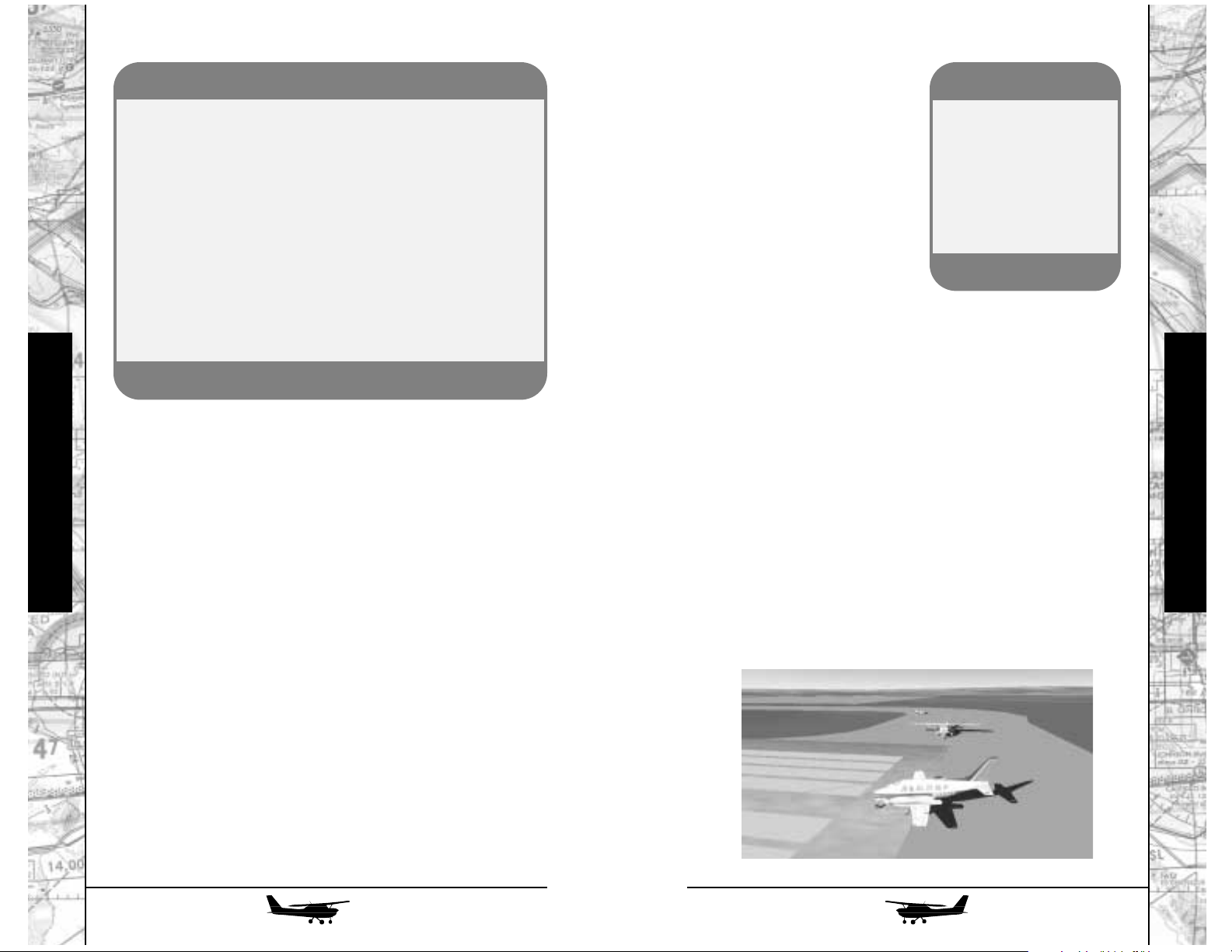
Turn the ignition key all the
way to the right, to the “start” position. The engine will crank. When
it fires, smoothly push the mixture
control all the way in. As soon as
the engine starts, check the oil
pressure gauge. If it doesn’t start to
rise within about 15 seconds, kill
the engine by pulling the mixture
control all the way out.
Once the engine has started,
turn the auxiliary fuel pump back off and verify that the ignition
key is at the “BOTH” position. You’ll see the annunciators go out,
and as the vacuum pumps come online, the artificial horizon will
go through a few gyrations, then settle down to a straight-and-level
indication. Turn on any exterior lights you’ll need. Although we
won’t be using the radio on this first lesson, turn on the avionics
master switch and watch all the radios come to life.
HEY, TAXI!
Now we need to get out to the active runway. (If the simulator has already positioned you on a runway, we’ll just taxi around
on it for a few moments to get the feel of things).
On the ground, the airplane is steered, not by the control
yoke, but by the rudder pedals. It’s very common, on a student’s first
flight, to find them twisting frantically on the yoke while the airplane
continues inexorably toward some obstacle! Make sure the parking
brake is released, add just a little power to get rolling, and try steering the airplane in gentle left and right turns using the rudder pedals (or the “twist” axis if you have a three-axis control stick).
LET’S FLY!
Return to a normal cockpit view and turn on the master
switch. Some of the annunciators at the top of the panel will light
up (they’ll blink for ten seconds, then stay on) and the small engine
gauges at the lower left of the panel will come to life. Check the
left and right fuel gauges to be sure they indicate the amount of
fuel you have on board.
ENGINE START
If you’re in a hurry, hit “E” on the keyboard and the airplane
will magically spring to life. You’re missing all the fun, though;
here’s the way the airplane is actually started:
Unlike earlier models of the 172, the current “R” model has
a fuel-injected engine which requires “priming” before startup especially if it’s cold. Check that the mixture control is in its idle
cutoff position (pulled all the way out); now “crack” the throttle,
i.e., pull it all the way back, then push it in about half an inch.
Note: if you have Auto Mixture activated, you cannot manually
alter mixture.
Now turn on the auxiliary fuel pump, and, while watching the
fuel flow gauge (lower left), push the mixture control in until you see
about 3 to 5 gallons per hour of fuel flow, then pull it back out.
SimTip
To get an accurate readout of any instrument
panel gauge, position
the mouse pointer over
it. A window will pop
up with a digital readout
of the current value.
Flight Instruction
Flight Instruction
82
83
SimTip: Pitch Trim
You’ll be using the pitch trim wheel a great deal in this, and
most other, airplanes. In the real airplane, you’ll be able to
reach for it without looking, and you’ll feel its effects directly,
as pressures in the control yoke. In the simulator, it can be
tedious to have to change your panel view every time you
need to make a trim change.
I suggest you either configure the switches on your control yoke (preferred) or stick to provide pitch trim; or use the
keyboard shortcuts (keypad 1 for nose up, keypad 7 for nose
down). If you have a force-feedback stick, you should be able
to feel the pressures changing. Otherwise, you’ll have to gradually release elevator pressure until the airplane holds the
pitch attitude you want “hands-off.”
Page 43

We’ll start with “C” for “CONTROLS.” Roll the yoke all the way
to the left; while holding it all the way over, pull it all the way
back; while holding it back, roll it all the way to the right; while
holding it to the right, push it all the way forward. You can confirm the control surface movement by switching to an external
camera. This is also called “boxing” the controls. What you’ve
done here has simultaneously proved that the ailerons and elevator move through their entire range, and that they don’t interfere with one another (for example, by the mysterious workings
of the yoke snagging a hanging wire somewhere behind the
panel) anywhere in that range. Note that merely rolling the yoke
from side to side at one particular elevator deflection, or pulling
the yoke all the way back and forth with the ailerons neutral,
doesn’t necessarily eliminate any possible interference; you need
to “box” the controls as just described. Finish by moving the rudder pedals all the way back and forth.
“I” stands for “INSTRUMENTS.” Take a general look across the
panel and verify that everything is reading about what it should be;
in particular, the engine instruments should show correct oil pressure, with both oil and cylinder head temperatures starting to come
up; the ammeter should show a slight charge. Now check the flight
instruments. The airspeed indicator should be at zero, the artificial
horizon should show wings level and either neutral pitch attitude or
barely above the horizon (depending mostly on how much air you
have in the nosewheel strut!). The altimeter should show field elevation above sea level. If it doesn’t, use the knob at its 7 o’clock position to adjust it. The turn coordinator should show a wings-level
indication, with its ball centered.
The directional gyro should agree with the “whiskey compass”
atop the instrument panel; it, too, has an adjustment knob at 7
o’clock. Finally, the vertical speed indicator should indicate zero
- its needle should point to the 9 o’clock position.
84
85
Tapping the brakes will slow
you down. For some active rudder
pedals, the top of each pedal actuates the wheel brake on that side
only, so you have to squeeze them
equally. You can use individual
brakes to tighten up your turn
radius on the ground.
Finish up your taxiing by lining the airplane up with the centerline of the runway, retarding the
throttle to idle, and braking to a stop.
BEFORE TAKEOFF
Every airplane has its own pre-takeoff checklist, and the one
for the 172R is reproduced in the appendix. However, you can
cover just about any airplane using simple mnemonics. Different
mnemonics are used in different countries and for different airplanes (for example, RAF fighter pilots say “TAFFIOHHH”), but the
one we’ll use here is simple: CIGARS.
I
C
Flight Instruction
Flight Instruction
SimTip
If you don’t have rudder
pedals or a three-axis
stick, use the bottom
two keys (0 and .) on the
numerical keypad for
rudder control. Keypad
5 centers the rudder.
Page 44

“G” stands for “GAS.” Check the left and right fuel gauges for
adequate fuel onboard, verify that the fuel selector is on “both”
and the fuel shutoff is pushed all the way in. We’ll leave the auxiliary pump off for the moment.
“A” stand for “ATTITUDE.” For once, this doesn’t mean how you
feel, or if you intend to get in my face later on; it’s your cue to
check pitch attitude, or, in this case, to verify that you have the
pitch trim set properly for takeoff. If it were mis-set, you’d either
have to exert a mighty heave to get the airplane off the ground;
or you might find the airplane leaping into the air before it, or
you, were really ready to fly.
“R” stands for “RUNUP,” and since there are several steps to this,
we’ll take them one at a time:
• Hold the brakes, or set the parking brake. Now, gradually
increase the throttle until you reach 1800 rpm.
• What we’re going to do now is check the engine’s two completely independent ignition systems. Each cylinder has not
one, but two spark plugs, and they’re fired by separate magnetos (often simply called “mags”). What’s a magneto? It’s very
similar to the ignition system of a car, and even includes a distributor - but instead of having points and an external coil (or,
in modern cars, an electronic ignition system), the magneto
generates its sparks internally, using a rotating permanent magnet (hence the name). This makes it entirely independent of the
airplane’s electrical system - the mags, and the engine, will
continue to run even if the airplane system fails altogether. (In
fact, old-fashioned airplanes don’t even have electrical systems, which is why they have to be started by the
"Hemingway” method of swinging the prop by hand - as in
A Farewell to Arms
.)
86
87
• Move down to the ignition switch. While watching the
tachometer, move the switch two “clicks” to the left, paradoxically labeled “R.” What you’ve just done is switched off one
of the engine’s two magnetos - in this case, the left one. The
engine should continue to run, but since it’s not quite as efficient with only a single spark to ignite the fuel/air mixture in
the cylinders, its RPM should drop slightly (50 to 100 RPM).
• Now switch back to BOTH, verify that the RPM comes back
up to 1800, then switch only one click to the left, to “L.” Once
again, the RPM will drop slightly. What you want to see here
is (a) that the drop is no more than 150 RPM on either mag,
and (b) that the difference between the two mag drops is no
more than 50 RPM. Make sure you finish by switching back to
BOTH once again.
• The final runup item in Cessna’s checklist is to check the vac-
uum gauge in the green arc. You might also glance at the
annunciator panel to ensure that it’s dark.
Thoughts differ as to how to handle the auxiliary fuel pump
on injected Lycoming engines like this one. The fact that the
engine performed normally during runup indicates that the
engine-driven fuel pump is working properly, so we should be
able to count on it from here on. On Lycomings, however, you
can also run the aux pump with no adverse effects (unlike on
Continentals, the other major brand, in which running the aux
pump along with the engine-driven one will flood out the engine
and kill it). If the engine-driven pump should fail right after takeoff, the engine will quit, leaving you with a busy situation at low
altitude - so in Lyc-powered airplanes, my personal practice is to
verify during runup that the engine-driven pump is okay, then
switch on the aux pump just as a backup for takeoffs and landings.
“S” is for “SAFETY”! Seatbelts on, doors latched, objects
stored, etc.
Flight Instruction
Flight Instruction
G
A
R
S
Page 45

88
89
TAKEOFF! (finally!)
The big moment has arrived. Crosscheck that with the artificial horizon; the miniature airplane should be just about on the
horizon bar.
Make sure the brakes are released, then smoothly apply full
power. The airplane will start to roll ahead. If you have FLY! set
for realistic flight modeling (and I strongly recommend that you do
- we worked very hard on its accuracy!), you’ll notice that the airplane will also try to veer off to the left.
This is not due to politics. Rather, it’s the combination of a
number of aerodynamic and physical effects, often grouped under
the (mostly incorrect) label of “torque.”
In fact, in this situation (airplane on the
ground), torque per se the tendency of the
engine to roll the whole
airplane opposite the
direction of propeller
rotation - plays a relatively minor role. Far
more significant, during
the takeoff roll, is the
fact that the air moving back from the propeller does so not in a
straight line, but with a spiral motion imparted to it by the propeller’s rotation (clockwise as seen from behind). Thus, there’s a
good deal of force pushing against the left side of the vertical fin,
thus shoving it to the right and pushing the nose to the left.
Just keep your eyes out the windshield, applying rudder as
necessary to keep the airplane tracking the runway centerline.
Glance at the airspeed indicator from time to time. As the speed
approaches 55 knots, apply gentle back pressure to raise the nose
to just barely below the horizon. The airplane will lift off - don’t
let it settle back to the runway. Let it accelerate to a climb speed
of 70 to 80 knots - remember, lowering the nose will let it speed
up, raising the nose will slow it. Now start breathing again.
We’ve moved right from takeoff into one of the four fundamentals: climb. At the same time, we’re going to try to keep going
straight ahead. To maintain a straight course, simply keep the
wings level (either with the real horizon if you can see it, or with
the artificial one). To control your climb airspeed, maintain the
correct pitch attitude - and, at this point, if you can’t see the horizon over the instrument panel, I’d suggest altering your cockpit
view until you can.
Keep climbing until you get to around 3000 feet. Now we’ll
level the airplane off and set cruise power to start working on
straight and level flight. The airplane will start to speed up. When
it gets to around 100 knots, reduce power to about 2100 RPM. It’ll
continue accelerating, although less strongly now, and the RPM
will creep up again toward 2200.
Why does the RPM change all by itself? Because this airplane has a fixed-pitch propeller. Think of the blade like the
thread of a screw, pulling the airplane through the air. Obviously,
since the air has some “give” to it, the relationship between airspeed and RPM isn’t totally locked in, but there’s still a very close
correlation - it’s as if we were driving a car that was always in the
same gear. We’ll play with this relationship a little more in just a
few moments.
STRAIGHT, LEVEL, STABILITY, AND TRIM
Sooner or later, everything should settle down: the airplane
will be flying straight ahead (wings level), neither climbing nor
descending (nose at the right distance below the horizon), and
the RPM and airspeed have stabilized around 2200 RPM and
105 to 110 knots. You’ll most likely find, however, that you have
to hold steady elevator pressure (most likely forward) to keep the
situation stable.
This is where the trim control comes in. Slowly actuate it in
the same direction you’re holding pressure until you can release
the pressure on the yoke or stick without the pitch attitude changing. The airplane is now “in trim,” and barring air turbulence, it
should fly straight and level with little or no input on your part.
Flight Instruction
Flight Instruction
“Torque”
Page 46
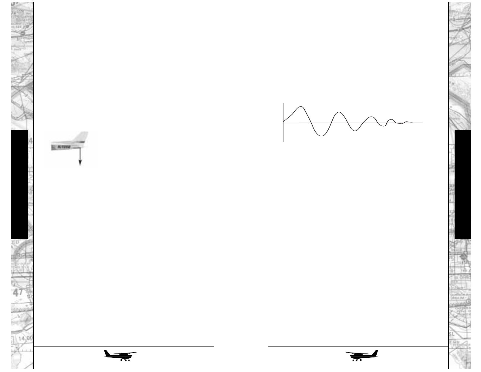
90
91
While it’s doing this, let’s take a moment to look at why it
can remain so stable on its own. (If it’s not quite doing that, go
ahead and pause the simulation).
Any certificated civil airplane has a fairly high level of pitch
stability. That is, when it’s trimmed for a certain speed (as we did
just now), it’ll tend to hold that speed even if displaced from it.
Let’s take a look at how this works.
You’ll see that the airplane is like a teeter-totter, balanced on
the point at which the wing exerts its lift (called, appropriately
enough, the center of lift). While a good deal of the airplane’s useful load (people, luggage, and fuel) is arranged near the center of lift
(either in front of it or behind it), there’s a significant chunk of iron
stashed away just about as far forward as you can get: the engine.
This means that the airplane’s natural
tendency would be to drop its nose. To
counteract this, the horizontal tail has an
airfoil similar to that of the wing - but
upside down! Thus, it’s actually pushing
downward, and thus balancing the airplane and keeping the nose up where it
belongs.
Now, you’ll recall from the introduction - you did read it,
didn’t you?—that the amount of lift an airfoil produces is in proportion to its airspeed. Let’s say, for example, that we hit a gust
that drops the nose of the airplane a bit. Since it’s now going
downhill, it’ll speed up - and as it does, the downforce generated
by the tail increases, thus bringing the airplane’s nose back up
toward level flight. Similarly, if something displaces the airplane’s
nose upward, it loses speed; the downforce created by the tail
decreases, allowing the weight of the engine in the nose to bring
the nose back down.
The process isn’t instantaneous. Let’s get back into the cockpit for a demonstration. Once you have the airplane trimmed out
for level flight, pull the nose up until the airspeed has dropped to
85 or 90 knots, then let go of the controls. (You can continue to
nudge them from side to side to keep the wings level, but don’t
make any pitch inputs or corrections. Or, since the 172 autopilot
doesn’t control any pitch functions, just turn it on and it’ll keep
the wings level for you.)
As soon as you turn the controls loose, the airplane will try
to return to its trim speed. In fact, since it’s now flying so slowly,
it doesn’t even have enough “tail power” to keep the nose up to
the normal level flight attitude; the nose will gently drop to somewhere below level flight attitude, and the airplane will speed up.
As it approaches its trim speed, the nose will start to come up
again…and, since we’ve now exceeded our trim speed in a gentle dive, it’ll rise a bit above level flight once again, then go back
down, come back up, etc.—a little less each time , until it’s settled back down at its trim speed.
Basically, then, the trim speed, at which the airplane is stable,
could be considered a “zero point.” All the trim control does is to set
at what airspeed that zero point occurs, so you can fly the airplane
at any speed you want without constantly having to hold pressure
against the controls.
Before we leave the trim control, let’s look at the other major
factor that affects airplane trim: power. With the airplane trimmed
up straight and level once again, and without touching the controls
(except, as before, use the autopilot or little sideways nudges to
keep the wings level), pull the throttle back to around 1900 RPM.
You’d expect the airplane to slow down, wouldn’t you?
Surprise! Its initial reaction is to drop its nose and even speed up
a bit!
Why? Because the horizontal tail is right behind the propeller - so the airspeed it “sees” is a combination of the airplane’s
actual forward speed and the thrust produced by the engine.
Reduce power, and there’s less air passing over the tail; thus, it
produces less downforce, and the nose comes down.
Flight Instruction
Flight Instruction
Tail Airfoil
Stable Pitch Damping
Time
Slower
Faster
Speed
Pull Up and Release
Page 47
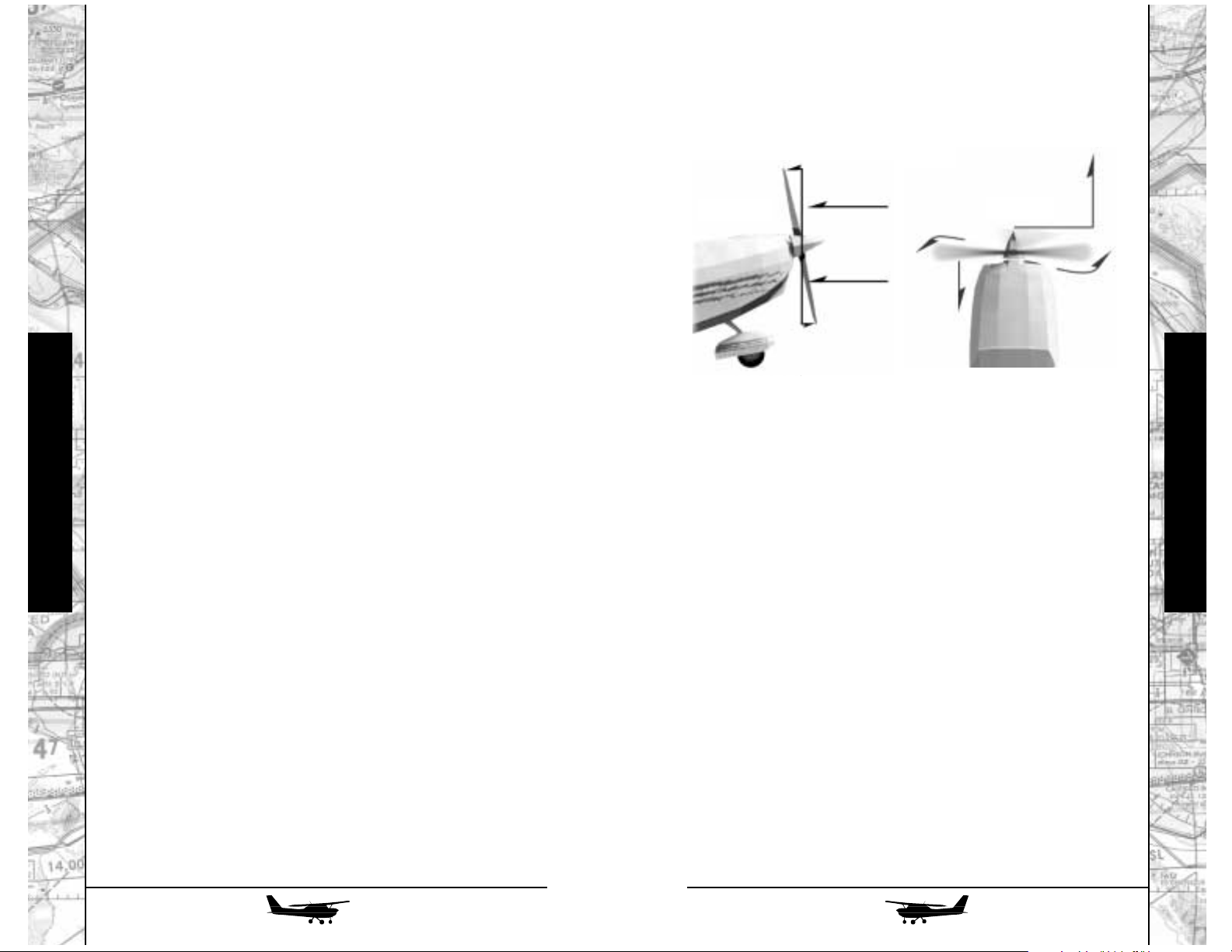
This time, while the spiraling propeller slipstream continues
to play a role, there’s another force: the notorious “P-factor.” This
is not to be confused with the distress pilots feel when they’ve
been flying for several hours after drinking too much coffee before
takeoff.
Take a look at this sketch to see what’s happening. When the
nose of the airplane is pointed up, the propeller isn’t just spinning
in a vertical plane. The downgoing blade (the right one for
American engines) is also moving forward, in the direction of
flight, while the upgoing (left) one is moving backward. Thus, the
right blade “sees” a higher airspeed, and takes a bigger “bite” out
of the air, than the left one.
This, in turn, means that the right side of the propeller is
doing more work, pulling harder, so its center of effort - the apparent point at which it’s pulling - is no longer in line with the propeller hub. Instead, it’s displaced some distance to the right (typically, up to half the blade length), thus pulling the nose of the airplane off to the left. In a steep, low-speed, high-power climb,
you’ll have to hold a good deal of right rudder pressure to keep
the airplane straight.
By the way, as you might expect, all Russian and many other
European engines turn the other way - and, sure enough, you need
a heavy left foot in their airplanes.
92
93
Now shove the throttle wide open. The nose comes up - and
while the airplane will ultimately settle down near its formerly
trimmed speed, it’ll first go a bit below it, for the same reason.
What if the tail weren’t right behind the propeller(s)? Sure
enough: airplanes with T-tails have much less trim response to
power changes.
CLIMBS AND DESCENTS
These little trim exercises lead logically into the next two
fundamentals: climbs and descents.
There are two ways to make the airplane go up and down,
and they can be used together or separately. Changing the pitch
attitude (within reason, of course), simply makes the airplane go
“uphill” or “downhill.” If you leave the power alone during such
changes, you’ll see the same reaction as if you were to drive a car
on a hilly road with the gas pedal locked in one position: it’ll slow
up going uphill, and go faster on the downhill stretches. Try it!
You can also adjust the power, as we did in the last trim
exercise. If you leave the pitch trim alone, and don’t use any control pressures, the results are also predictable: reduce power, and
the airplane will go downhill (possibly speeding up a bit as well);
add power, and it’ll climb, possibly slowing.
In the real world, of course, you use both controls at once. To
climb, raise the nose to get the airplane to an efficient climb speed
(70 to 80 knots works well in the 172) and adjust the power to get
the rate of climb you want. In a real-world 172, particularly if you
have a couple of buddies along on a warm day, you’ll typically use
full throttle and accept whatever rate of climb you can achieve—
“She’s givin’ye all she’s got, cap’n!” To descend, set your pitch attitude for the desired airspeed (typically cruise speed or a bit more),
then set power to achieve the desired rate of descent without
exceeding the redline RPM.
Here’s a fine point: just as on takeoff, you’ll notice that as
you add power and pull the nose up for a climb, the airplane
wants to veer to the left.
Flight Instruction
Flight Instruction
Downgoing blade takes
bigger bite.
Center of effort is displaced
to the right.
P-Factor
Top View
Side View
Page 48
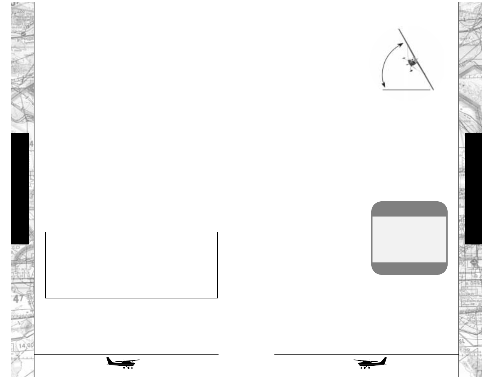
94
95
time, look out the front and pay
close attention to what the nose is
doing relative to the horizon.
As we start the turn, it’ll try
to drop a bit - that’s because the
airplane is sinking a little, and its
natural stability (as discussed earlier) wants to point the nose down
to compensate. What do we do?
Simple - we add just a bit of back
pressure during the turn. If you
note exactly how far below the
horizon line is before you start a turn, then add back pressure as
necessary while turning, the turn should come out level.
Now let’s try a real steep turn - we’ll start this one to the left.
Roll the airplane into a 60-degree bank - that’s the second large
mark at the top of the artificial horizon.
You’ll notice a couple of things right away. One is that the
airplane turns a lot faster; the other is that it will take lots more
back pressure to keep the nose up. You’ll also notice that a lot of
airspeed will get scrubbed away: to maintain altitude in a 60degree bank requires so much
back pressure that you’re putting
a constant load of 2 G’s (a “G” is
equal to the normal force of gravity) on the airplane; all of a sudden, that poor little Lycoming has
two whole 172’s bolted onto it!
That rustling noise you hear
behind you is the passengers getting those little waxed paper bags
out of the seatback pockets…
TURN COORDINATION
Something else you may have noticed, especially during the
steep turns, is that the ball in the turn coordinator instrument might
have been doing some weird things.
This is because the airplane doesn’t always want to go where
it’s pointed (or, conversely, point where it’s going).
ONE GOOD TURN DESERVES ANOTHER
Let’s return, once again, to trimmed straight-and-level flight.
Now we’re going to try some turns to either side - first gentle ones, then steeper. Remember, turns in an airplane are made
by directing part of the lift in the desired direction, and we do this
by banking.
Let’s try one to the right. Note the heading shown at the top
of the directional gyro - that’s the direction we’re headed right now
- and the direction at the 3 o’clock position, 90 degrees away,
which is where we want our turn to finish up. Got it? Fine…now
start applying gentle pressure to the right on the yoke while looking
out forward at the horizon. The airplane will start to bank to the
right. Glance at the artificial horizon. When the bank has reached
30 degrees, the first large mark (past the two smaller ones) at the top
of the instrument, roll the yoke back to the center.
You’ll notice that the airplane tends to hold whatever bank
it has with the yoke centered. As you rolled into the turn, it started turning (changing its heading) to the right. With the yoke centered to maintain the 30-degree bank angle, it continues turning
right. As you approach your planned new heading, you’ll do just
the opposite: roll the yoke to the left to bring the wings back level,
then center it once again to keep them there.
Thus, you see that a turn in an airplane is actually requires
four separate control movements:
Pretty cool, huh? Except that chances are, now that you’re
back in level flight, that we’ve lost some altitude. Why? Because
any lift that we use to make us turn (by banking) is that much lift
taken away from the basic task of keeping the airplane up in the
air. Let’s turn to the left, back to our original heading - but this
SimTip
You’ll need some form of
rudder control (either
pedals or the keypad 0
and period) for these next
maneuvers.
Flight Instruction
Flight Instruction
60 Degree Bank
1. a roll-in to the desired bank angle.
2. re-centering the controls (with minor adjustments as
necessary) to keep the turn going without letting it get
either shallower or steeper.
3. then an opposite roll-out to return to level flight.
4. another re-centering of the controls after that.
Page 49

96
97
Cessna 172R -
Intermediate
THE DREADED STALL
In this lesson, we’ll begin by looking at what some students
consider a stressful maneuver - at least (and probably only!) the
first time around. This is the stall: the condition in which the airplane is maneuvered to, and past, the critical angle of attack, at
which the airflow separates from the wings and the production of
lift effectively ceases.
Notice that at no point have I said “stalling speed,” and
that’s entirely intentional. I’m trying to underscore, here, that a
stall is solely the result of exceeding the critical angle of attack.
True, in many flight regimes, this exceedance often comes at low
airspeeds - but it’s important to remember that, with a hard
enough pull on the yoke, it can come at any speed. We’ll look at
some of these “accelerated stalls” as we go along.
Let’s begin by getting the airplane up to a safe altitude for stall
practice. This means at least 3500 feet AGL; I’m even happier at
5000 feet. Not that it takes nearly that much altitude to recover from
a stall, of course; in fact, later on, we’ll practice recovering with
minimum loss of altitude. On the other hand, a botched recovery
can eat up quite a bit of altitude, particularly if you let it develop
into a full-blown spin. And since the 172R, when operated in utility category (no more than two folks, half fuel, and no baggage), is
signed off for spins…yes, we’ll do those, too (urp!).
If you want more practice in engine start, taxi, and takeoff, by all
means use the opportunity. On the other hand, if you don’t want to
take the roughly ten minutes we’ll need to get off the ground and up
to 5000 feet, just pre-position the simulator to an appropriate location
and altitude.
LOOK OUT BELOW!
The first thing we’ll do before any stalls is a couple of steep
turns, one in each direction. These are called clearing turns, and
they serve two purposes. Not only do they loosen you up a bit,
and let you get the airplane “in hand;” if they’re steep enough
(let’s use 45 degrees), they also give you a chance to look out the
side windows and make sure there’s no one flying right below us,
in the airspace we’ll descend into during the stalls.
Flight Instruction
Flight Instruction
First, let’s try something weird: rather than using the yoke,
try to make a turn simply by applying full rudder in the direction
you want to go.
The airplane will, in fact, try feebly to turn; it will even drop
the appropriate wing a little. Mostly, though, it’ll just sort of slither along sideways, going more or less the way it was to begin
with, and with the ball in the turn coordinator all the way to the
outside of the turn.
What’s happening? This is a great illustration of how lift,
aimed by banking, rather than the rudder, is what actually turns
the airplane. All you’ve managed to do is point the nose a bit to
the inside of the turn (and, given enough time, the change in
engine thrust direction will, in fact, change your direction altogether); but it’s pretty ineffective, and also uncomfortable as centrifugal force slings you, your passengers, and the skid-indicating
ball to the outside of the sloppy turn.
Now let’s try the other extreme: rack the airplane over into
a steep turn, using the yoke only, without any rudder pressure.
The ball will drop to the inside of the turn. The nose, however,
may not point all the way into the turn; indeed, as you start the
turn, it’ll momentarily slew in the opposite (outward) direction,
since the aileron on the raised wing produces more drag than that
on the lowered one (a phenomenon called “adverse yaw”).
The function of the rudder is to balance out these forces. In
a properly executed (“coordinated”) turn, the ball will remain centered throughout, and passengers should not feel “the leans” in
either direction - in fact, if they can’t see out, they shouldn’t even
know you’re turning. The ball will always move away from the
side with excessive rudder pressure, so if in doubt, the rule is simple: “step on the ball,” adjusting rudder pressure until it’s in the
middle between the index lines.
THE EASY WAY OUT
We’ve done a lot of work for a first lesson. If you’re feeling
feisty, you can try to get the airplane back onto an airport by hitting the M key to bring up a local map, turning the airplane until
you’re headed for a blue or magenta airport symbol, then using
your own combination of turns, descents, and power adjustments
to get down onto the end of a runway. In a real airplane, your
instructor would take you home at this point - if you’re ready for a
break, just hit the Z key to activate Auto Land.
Page 50

98
99
Meanwhile, back in the air: keep increasing back pressure
as the airspeed decreases. Right around the bottom of the green
arc, depending on how you have the airplane loaded, one of two
things will happen:
Either way, you’ve “stalled” according to the FAA. In the first
case, there’s been an actual separation of the airflow over the
wings, and the airplane has started to drop. In the second case,
you’ve run out of elevator control; the airflow is at least partly separated, and you’re not producing enough lift to hold the airplane up
(hence the rapid rate of descent). In addition, in either case, you’ll
have noticed that the airspeed has rapidly decreased quite a bit
more: as the airflow begins to separate, drag increases radically.
NOW WHAT?!
At least you’ve noticed that the airplane merely sinks - it
doesn’t “plummet” (at least the very docile 172 won’t). Still, if this
sinking isn’t arrested before you reach the ground, it’ll be unfortunate. To recover, all we have to do is to reduce the angle of
attack so the airflow reattaches to the wing, and we do that by
reducing back pressure. Notice that unless you’re in an extreme
situation, you don’t need to shove the yoke all the way forward;
if you do, you’ll certainly un-stall the airplane, but you’ll also
plaster your passengers onto the ceiling and lose a lot of unnecessary altitude.
Just lower the nose a bit below the horizon; at the same time,
open the throttle all the way. Hold the nose on the horizon as the
airplane flies out of the stall. Don’t try to pull up again; you’re still
at a low speed and high angle of attack, so a secondary stall isn’t
far away.
THE EASY ONE FIRST
Get the airplane trimmed up for a normal cruise and make
your clearing turns. When you’re recovered to straight and level
flight, ease the power back to idle. The nose will try to drop, but
don’t let it. Instead, bring it up above the horizon about ten
degrees; what we’re looking for is a gradual and constant slowing,
with the airspeed ideally reducing by one knot per second.
You’ll notice that as the airplane slows, it takes more and
more back pressure to hold the pitch attitude. Glance at the airspeed indicator. As it reaches a point 5 to 8 knots above the bottom of the green arc (the flaps-up level stalling speed at maximum
weight), you’ll start to hear a mournful whine.
This isn’t your passengers (actually, it might be). Built into
the root of the left wing is a little air horn, plumbed to an opening
in the wing’s leading edge. In normal flight, the opening senses normal, or even higher than normal, air pressure. As the angle of attack
increases, however, the stagnation point - the point on the leading
edge at which the air splits to go above and below the wing - moves
downward. Just before stalling angle of attack, it’s moved far
enough that the opening is now on the upper, or low-pressure, side
of the stagnation point. Air is sucked out through the horn, and
that’s the stall warning sound you hear. It’s a simple, reliable system,
requiring no electricity or moving parts.
In fact, if you’re tall, you can check it during preflight
inspection by placing your mouth over the opening and sucking
gently; you’ll hear the horn. An instructor of my acquaintance
used to suck so hard that he’d damage the horns until a mechanic prepared an airplane with a few squirts of Tabasco just inside
the opening…
1. The airplane will give a little shudder and its nose will
drop a foot or so; a wing may drop a bit as well. You’ll
feel a definite “sinking sensation.”
2. (More likely): You’ll “run out of stick”—you’ll have the
yoke as back as far as it will go. The airplane will sort of
tiredly ease its nose back down to the horizon, possibly
with a bit of shuddering and shaking, and the VSI will
show a rapid descent.
Flight Instruction
Flight Instruction
Full Stall
Page 51

100
101
SLOW FLIGHT AND APPROACH TO
LANDING STALLS
Now we’re going to explore the effect of the flaps on the airplane. The big “barn door” flaps on the 172 move backward, as
well as downward, as they extend. This makes them very effective
for increasing lift: not only do they increase the curvature of the
wing by lowering its trailing edge, but they increase its area as
well.
At full deflection, they also create a great deal of drag. The
172’s flaps can be set at any position between full up and full
down, but pilots typically use
the three “notches” in the flap
control. The first notch, at 10
degrees, produces much more
lift than it does drag; it can also
be extended at speeds up to 110
knots. Full flaps, at 30 degrees,
create much more drag than lift;
you have to be below the top of
the white arc, at 85 knots, to
lower them. The 20 degree
notch “splits the difference”
between lift and drag, but is subject to the same 85-knot speed limitation. (Older 172’s had a final
notch at 40 degrees that let them come down like parachutes - but
left you so little energy for a soft landing that you really had to
know what you were doing!)
Set the airplane up in level cruise flight and engage the
autopilot so you don’t have to worry about keeping the wings
level (remember, the autopilot in the 172 has no control over the
pitch axis). Make sure the airspeed is below 110 knots. Now lower
the first notch of flaps.
You’ll notice an impressive pitch-up and “ballooning”—the
airplane will gain a couple of hundred feet of altitude. This is
because you’ve created a major increase in the wing’s lift without
changing the amount created by the tail. Wait until the airspeed
settles down again and note its new value. It’ll be lower than it
was before, the airplane will be at a slightly lower nose attitude,
and it’ll be descending slightly.
Practice this several times. What you’re working toward is a
recovery with minimum loss of altitude once the stall “breaks.”
DEPARTURE STALL
To the extent that the 172 can be goaded into a full stall at
all, the ones we just did were the easiest and most docile. Now
let’s look at another type: the departure stall, in which we simulate someone trying to climb too steeply after takeoff.
In level flight, after making your clearing turns, pull the
throttle back to or near idle, holding your altitude and letting the
airplane decelerate to near its normal takeoff speed of around 60
knots. Trim as necessary, or just set the trim at the takeoff mark.
As you reach 60 knots, apply full power, pull the nose up to
and beyond a normal climb attitude, and let the speed start bleeding off. One thing you’ll notice right away will be that it’ll take a
lot of right rudder to keep the airplane headed straight with the
skid ball in the middle of its tube.
Since you’re now carrying part of the airplane’s weight with
power, the airspeed indicator will go perceptibly below the green
arc before the stall actually “breaks.” You’ll still get 5 to 8 knots
advance notice from the stall warning horn. The pitch attitude
before the break will be quite a bit steeper, and the break will be
sharper, with the airplane possibly getting further nose-down than
in the first stall series. If you didn’t have the rudders just right,
there’s also a good chance that a wing will drop - most likely the
left one.
You’re already at full power, so the object now is to recover
with as little altitude loss as possible. Relax just enough back pressure to get the airplane flying again, then bring the nose up near
the horizon to arrest the sink rate, but don’t pull so hard you stall
again. As the airplane picks up speed, you can reduce power to a
normal cruise setting.
Flight Instruction
Flight Instruction
The air flowing through the slot
between the wing and the flap
helps keep the overall flow
attached at very high angles
of attack .
Page 52

102
103
“THE BACK OF THE CURVE”
Now for a rather interesting exercise. Start out with the airplane in trimmed level flight, then gradually reduce power to
about 1750 RPM and re-trim until you’re flying just below the top
of the white arc. Next, extend the flaps to the second notch, wait
for the “balloon” to run its course, and trim once again for level
flight. The airspeed should settle around 70 to 80 knots.
Notice what your tachometer is indicating - due to the fixedpitch prop, it’ll have changed a bit as we slowed. Now, using elevator and trim, slow the airplane by ten knots; then, holding it at
that airspeed, adjust the throttle until we’re neither climbing or
descending. Look at the tach again, and you’ll see that we’ve
reduced power a bit more. Stands to reason, doesn’t it? To go
slower, use less power…
Okay. Now reduce the airspeed another ten knots - carefully, we’re pretty close to the stall, and you may hear the horn intermittently - and, once again, adjust power to maintain altitude.
Guess what? It takes more power this time! We’re flying slower,
but it takes more power to do it.
We’ve entered what’s known as the “region of reversed command,” also called “the back side of the power curve.” Down to a certain speed, the airplane seems to be following the rules - more power,
more speed. Below that, however, everything seems backward.
What’s happening here is that as we approach the critical
(stalling) angle of attack, any small increase in angle of attack
causes drag to build up even faster than lift. This is why we have
to be so cautious as we approach a stall - as we get close, the airplane has a tendency to “dig in,” if we don’t pay attention to angle
of attack, and slow itself even further.
Okay - as long as we’re down here, somewhere below the
bottom of the green arc, let’s try some gentle turns. This is called
“maneuvering at minimum controllable airspeed,” or simply
“slow flight,” and it’s an excellent exercise. Remember, stall speed
goes up with increasing bank angles (we’ll explore that more in a
bit), so make all your turns very gentle.
Finally, let’s reduce the power to or near idle, and let the airplane start descending so that it maintains airspeed. After we have
things stabilized, extend the final notch of flaps, continuing the
descent. To make things even more interesting, start a gentle turn in
either direction.
At this point, we’ve added more lift than drag. Many pilots will
blithely say “the 172 has a big nose-up trim change when you
extend the flaps,” and in a sense, they’re right: it does, at least at first.
However, until your use of trim is completely instinctive, rather than
trimming madly nose-down, then having to trim back nose-up as the
airspeed dissipates, just sit tight for a moment and you’ll find the trim
change wasn’t nearly so large as you thought.
With all these ruminations, we’re probably down below 110
knots now, so run out the second notch of flaps. Again, there’s a
nose-up trim change and a bit of ballooning, but less than the first
time. This is due partly because we have less airspeed, and thus
less energy, starting out, and partly because the flaps are now transitioning from “pure lift” to a more balanced “lift and drag”
regime. Again, wait until the airplane has settled down. Again,
we’ve shed some airspeed; the nose is down further yet; and
we’re descending a bit faster.
Finally, since we’re now well within the white arc, extend
the flaps all the way. The “balloon” will be very slight, but even
more speed will dissipate, the nose will go down further yet, and
the sink rate will increase. Throughout this evolution, we’ve
touched neither the yoke, the throttle, nor the trim.
All right - now, in one swell foop, bring the flaps all the way
up. The airplane will drop its nose and sink like a rock, at least for
a moment - but as it accelerates, the nose will come back up, and
if you’ve really been honest about not touching pitch, power, or
trim, sooner or later (after a few mild “dipsy doodles”) you’ll be
back at trimmed level speed.
What you’ve experienced here is that the flaps can be used,
not only to configure the airplane for slow flight, but for control.
Particularly as you start flying on instruments, when you’ll have to
keep track of a whole lot of things at once, you’ll find it a mark of
professionalism to control the airplane not only with pitch and
power, but also (and in some cases primarily) with configuration
changes. This will become even more important as you move into
higher-performance aircraft.
Flight Instruction
Flight Instruction
Page 53

LET’S HEAD FOR THE BARN
At this point, you’ve been exposed to all the maneuvers and
skills you need to land the airplane, so let’s try one. We’ll be using
our “four fundamentals” to fly a series of turns and descents
around the airport, culminating in a descent to the runway and an
approach to a stall just above it. How far above it, in case the airplane actually stalls? Oh, six inches or so…
First, of course, we have to find the airport.
For the moment, we won’t worry
about radio communications or other
traffic, but we do need to know the airport’s elevation above or below sea
level. If you’re using one of the San
Francisco Bay area scenarios, any of
the major airports right around the bay
are near enough to zero not to matter.
We’re going to use a pattern altitude of
1000 feet above the airport, so check
its elevation (printed below the airport
symbol), then start a gentle descent to
an altitude 1000 feet higher. We’ll also assume, for the moment,
that there’s no wind, so it doesn’t matter which runway we
choose; in the real world, of course, we’ll always choose the runway most nearly aligned into the wind.
Take another look at the airport
symbol, which will have at least one
runway depicted as a light-colored line.
If there are several, pick the one most
nearly aligned with the direction from
which we’re approaching. Even though there’s no wind, we’re not
going to land straight in, but rather fly a standard pattern. This is
partly to develop good habits, but even more because the pattern
offers you a lot more opportunities to judge distance, altitude, and
descent rate.
As we get closer to the airport, level off at pattern altitude
and set power for around 90 to 100 knots. Don’t fly straight at the
middle of the airport; instead, aim a bit to the right. We want to
start the first, or downwind, leg of the landing pattern at 1000 feet
above the ground and about a mile to the right of the runway, so
that you’ll be able to see it out the left side of the airplane.
104
105
What we’re about to do is called an “approach to landing stall.”
We have the airplane configured as if we were going to land, and
we’re descending as we would in the landing pattern. Pick an altitude
a couple hundred feet below where we are now, and when you
reach it, apply back pressure to try to level off without adding power.
You’ll notice it won’t take much back pressure to stop the
descent - indeed, you’ll be able to do so with the nose still perceptibly below the horizon. Moreover, with all the drag of the flaps,
speed will bleed off pretty quickly.
By now, we’re well below the bottom of the green arc - the
speed at which the airplane would stall with the flaps up - and, as
we approach the bottom of the white arc, with the horn moaning
away, the airplane will stall. Considering how much lift we’ve been
trying to produce, and how quickly it goes away, the “break” may
be surprisingly brisk, and it will most likely be accompanied by a
pretty quick wing drop (usually to the inside of the turn unless
you’re a real lead foot on the outside rudder).
How to recover? As always, by relaxing back pressure, adding
full power, then gently starting to bring the nose back up to minimize the loss of altitude. Use rudder as well as (or even more than)
aileron to help raise the lower wing. As soon as you start the recovery, you can bring the flaps back up to the first notch to help acceleration - but don’t bring them all the way up until the airplane is
both accelerating and climbing, because there’ll be some settling as
they come up the last ten degrees.
What are we trying to show here? Among other things,
that the nose doesn’t have to be above the horizon for the airplane
to stall - his time, it let go with the nose down. Also, this maneuver shows that the flaps-down stall can be fairly brisk, and that it
can take a good deal of altitude to recover…and since the realworld scenario for this type of stall is in the landing pattern, at less
than 1000 feet above the ground, this is a type of stall that should
be avoided at all costs.
Flight Instruction
Flight Instruction
SimTip
Hit the Mkey to
turn on the map
display, then turn
the airplane until
it’s pointed at one
of the blue airport
symbols.
Airport
Symbol
Page 54

106
Before we go any further, set your directional gyro (which
has probably drifted during our earlier flights) to match the magnetic compass on top of the panel. As you get close enough to the
airport, you’ll see the big numbers painted on the ends of the runways. These represent the magnetic heading of the runway, minus
the final zero - for example, 9 would be a heading of 90 degrees,
24 would be 240 degrees, etc. Obviously, each runway has two
numbers, 180 degrees apart, painted on each end: the other end
of runway 9 is runway 27, the other end of runway 24 is runway
6, etc.
Pick the runway you’re going to use, note its number, and
turn the airplane so you’re flying 180 degrees opposite that direction (called the reciprocal heading). If you don’t feel like the mental math, just turn to parallel the runway, with the reciprocal heading at the top of the directional gyro and the direction in which
you’ll be landing at the bottom.
About halfway along the runway, extend the first notch of
flaps and trim, if necessary, to maintain level flight. Keep an eye,
not just straight ahead, but out to the left. When your planned
touchdown point is below the left wingtip, reduce power a couple of hundred RPM and begin a gentle descent - no more than
500 feet per minute.
Keep looking to your left as well as checking forward. When
the end of the runway has moved back to about the 8 o’clock
position, you’ll start your base leg by making a smooth 90-degree
turn to the left. Roll out of the turn, and the runway should be at
about the 11 o’clock position. This is a good time to extend the
second notch of flaps, adjusting trim and power as necessary to
maintain a smooth descent at 70 to 80 knots.
As the runway moves back to the 10 o’clock position, start
another smooth 90-degree left turn. As you roll out, the runway
should be straight ahead; if you plan to use the rest of the flaps
(there’s no law that says you have to - in fact, the airplane lands
just great with no flaps at all), this is a good time for them.
The hardest thing for early students to judge is the correct
angle of descent, but most larger airports will help you out.
Depending on where you are, you’ll either see a pair of light bars
on the left side of the runway (the Visual Approach Slope
Indicator, or VASI), or a single line of four lights (the Precision
Approach Path Indicator, or PAPI).
Flight Instruction
They work in a very similar fashion. Using VASI, if you see
two white light bars, you’re above the optimum glide path; if the
further bar is red and the nearer one is white, you’re right where
you should be; and if they’re both red, you’re too low, and should
add power right away.
With PAPI, the resolution is even more precise. Four white
lights mean you’re quite a bit too high; three whites and one red,
still high, but not as much; two white and two red, just right; one
white and three red, you’re low; and four reds, you’re really low again, add power and climb back up to the correct glide path.
Either way, keep your wings level, making small corrections
to stay lined up with the runway centerline; use elevator, and trim
if necessary, to control your airspeed; and make judicious power
adjustments to control altitude and glide path. As you get right
over the end of the runway, don’t look at the ground right ahead,
but at the far end of the runway. In the 172, if you simply raise the
nose until the top of the instrument panel is just about on the horizon, then gently wipe the power all the way off while holding the
nose in that position - remember, it’ll try to drop as you remove
the power, so be ready to add a little more back pressure - you’re
almost guaranteed a creditable landing.
Squeech! Congratulations! We’re on the ground, but you
can’t relax quite yet—“the airplane isn’t done flying until it’s tied
down.” Carefully apply the brakes to slow down, and remember
that once on the ground the airplane steers with the rudders, not
with the yoke - I’ve had otherwise excellent students “grease on”
their first landing, then sit there twisting the yoke as the airplane
sashays toward the edge of the runway…
…but you’re too sharp for that, aren’t you? Welcome to the
world of fliers…and, since it’s traditional to cut off a student’s
shirttail to commemorate his or her first solo, I hope you were
wearing an old one today!
Flight Instruction
107
Landing Attitude
Perfect
Nose too low,
too fast!
Nose too high,
too slow!
Page 55

Cessna 172R
Before Takeoff Checklist*
Cessna 172R - Advanced
1. Flight controls . . . . . . . . . . . . . . . .FREE & CORRECT
2. Flight instruments (DG/Altimeter) . . .CHECK AND SET
3. Fuel quantity . . . . . . . . . . . . . . . . . . . . . . . . .CHECK
4. Mixture . . . . . . . . . . . . . . . . . . . . . . . . . . . . . . .RICH
5. Fuel selector valve . . . . . . . . . . . . . .RECHECK BOTH
6. Elevator trim . . . . . . . . . . . . . . . . . . . .SET for takeoff
7. Runup: . . . . . . . . . . . . . . . . . . . . Throttle 1800 RPM
8. Magnetos . . . . . . . . . . . . . . . . . . . . . . . . . . . .CHECK
9. Suction gauge . . . . . . . . . . . . . . . . . . . . . . . .CHECK
10. Engine instruments . . . . . . . . . . . . . . . . . . . . .CHECK
11. Annunciator panel . . . . . . . . . . . . . . . . . . . . .CHECK
12. Strobe lights . . . . . . . . . . . . . . . . . . . . . .AS DESIRED
13. Radios and avionics . . . . . . . . . . . . . . . . . . . . . . .SET
14. Autopilot . . . . . . . . . . . . . . . . . . . . . . . . . . . . . . .OFF
15. Wing flaps . . . . . . . . . . . . . . . . . . . . . .SET for takeoff
16. Brakes . . . . . . . . . . . . . . . . . . . . . . . . . . . . .RELEASE
Flight Instruction
(or as required for high altitude takeoffs)
(none illuminated)
(0-10 deg.)
ONWARD AND UPWARD
In this section, we’re going to try a few more advanced flight
maneuvers, including a potentially life-saving emergency procedure and a couple of spins; and we’ll take our first, very basic,
look at the arcane techniques of instrument flying.
Why do we choose to do these in the 172? In the case of
spins, it’s simple: of the airplanes in this release of FLY!, this is the
only one in which spins are authorized. In fact, in the real world,
none of the others were even intentionally spun during certification flight tests - so, to some extent, whether or not the Malibu,
Navajo, or King Air would recover from a spin is a matter of conjecture; and it’s a fair bet that the Hawker 800XP jet wouldn’t.
As far as instrument flying is concerned, we’ll cover only the
very basics that a private pilot needs to know: essentially, if you
fly into a cloud and lose visual reference, how to either fly out the
other side or turn around without wrapping the airplane up into a
spiral. We’ll leave radio navigation and instrument flying for later
on and bigger planes; not only are they more stable, but they have
more sophisticated instrumentation that’ll make your job easier.
LET’S DO THE “MUSH”
No, it’s not the latest dance craze - it’s a confidence builder,
as well as being a good way to use up excess altitude on practice
flights. As usual, we’ll start out at a normal cruise; any altitude
above about 2000 feet will be fine.
Flight Instruction
*Note that all Final Checklists assume that you are at the
end of the runway with the engine(s) running, with the
sole exception of the Malibu Mirage.
108
What would you do if you had an engine failure? You’d just
pick someplace and land - after all, the airplane glides just fine,
and you typically have the power all the way back at idle during
the last few moments of every landing anyway.
But what about at night, or in bad weather, when you can’t
see the ground? Let’s try a “mush,” not unrelated to “flight at minimum controllable airspeed,” but without power. Slow the airplane from cruise, pull the throttle to idle, and, as we get down
into the white arc, extend your flaps all the way.
109
Page 56
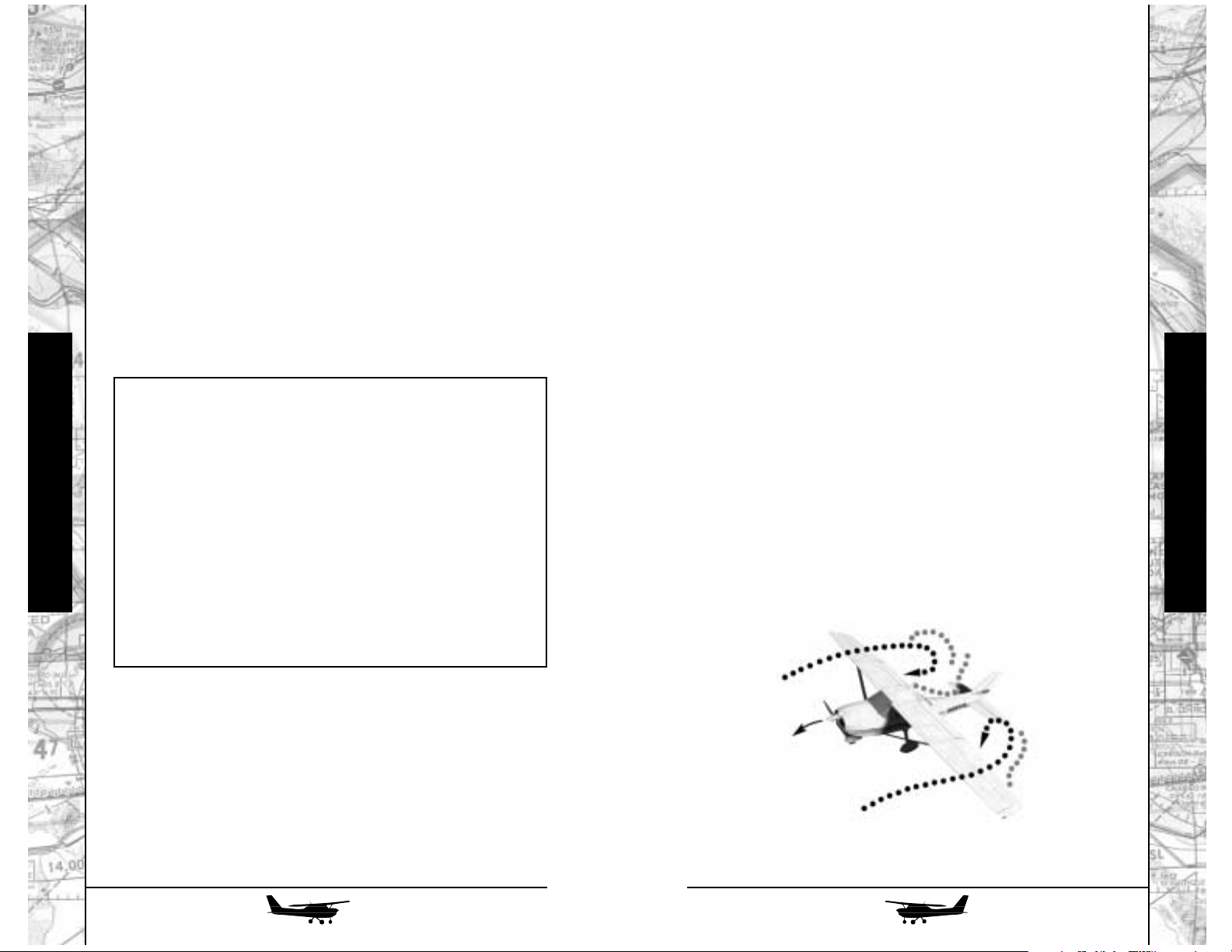
110
111
BANKING AND YANKING
We’re going to take a final look at a few specialized stalls,
so let’s start out with the airplane cruising at a reasonable altitude
- say, 5000 feet. Get it trimmed out for a gentle cruise at around
100 knots.
Roll into a steep turn, either way, and once you get the turn
established, with enough back pressure to keep the nose at the
right height below the horizon, add even more back pressure and pull it in pretty briskly. Surprise! You’ll hear the stall warning
horn and, if you keep pulling, the airplane will let go in a fairly
sharp “stall break.” As it does, glance at the airspeed indicator:
you’re still well up into the green arc, many knots above what
you’ve come to think of as “stall speed.” Go ahead and recover to
level flight.
What you’ve just experienced is an “accelerated stall,” and
what you’re learning here is, once again, that the airplane doesn’t
have to be flying slowly to stall - it’s a matter of angle of attack,
not speed. Where might you run into this situation? Perhaps if
you’re maneuvering hard to avoid another airplane - or, in a higher-performance airplane, if you come steaming into the traffic pattern at some impressive speed, then realize you’re going to have
to turn hard to avoid overshooting your desired downwind leg.
Now, using back pressure and trim, see how slowly you can
fly. Depending on loading, you’ll probably get down below 50
knots, with a rate of descent not much more than 1000 fpm.
What’s important about this? Well, if you can hold this attitude and speed all the way to the ground, and as long as you have
your shoulder harness fastened, the ensuing impact, even if you
can’t see the ground to make a more normal emergency landing,
will certainly be survivable - and one you may very likely walk
away from, if a bit banged up. (Unfortunately, this technique
doesn’t work nearly so well in airplanes bigger and faster than the
172.) Sure, the airplane will be a write-off; but, as they used to
teach in the RAF, “If a prang appears inevitable, strive to strike the
cheapest, softest object in the vicinity, as gently as possible.”
Thus, in case of an engine failure at night, we can develop the fol-
lowing checklist:
1. Extend full flaps.
2. Confirm fuel supply ( you may just be out of fuel in one
tank).
3. Slow the airplane to minimum “mushing” speed and trim
for it.
4. Ensure shoulder harness is fastened.
5. Pull Fuel Cutoff knob to reduce risk of fire upon landing.
6. At about 100 feet above your best estimate of the terrain
altitude, turn on the landing light.
7. If the terrain visible in front of the airplane appears unsuitable for landing - turn the landing light back off!
Flight Instruction
Flight Instruction
Accelerated
Stall in a Bank
Page 57

ALL CROSSED UP
Next, let’s look at something that’ll seem counterintuitive at
first: intentionally un-coordinated flight. Thus far, we’ve been
using the rudder to keep the skid ball centered. Now, however,
we’re going to use aileron one way and rudder the other to perform a sideslip.
Start a normal turn in either direction - but once it’s established, feed in a footful of outside rudder. The skid ball will drop
toward the inside of the turn - and, on a larger scale, so will the
airplane altogether. Take a look at the VSI, and you’ll see an
impressive rate of descent. This is a “slipping turn,” and while it
feels uncomfortable - in the real airplane you’d feel yourself leaning to the inside - its’ a very handy way of losing altitude.
Even more precise is a forward slip. First, let’s return to level
flight. Now, gently lower either wing, as if you were starting a turn
- but, at the same time, feed in just enough opposite rudder so the
airplane keeps going straight ahead. Actually, while it’ll maintain
the same track across the ground, the nose will move toward your
“heavy foot,” and if you could see the airplane from above, you’d
see that it would be moving crabwise.
This is actually a very useful maneuver in a couple of different landing situations. First of all, if you’ve botched your landing
pattern and find yourself way high on final approach, a forward
slip like this is a great way to get rid of excess altitude without
building up excessive airspeed. (Be aware, however, that Cessna
recommends against slips if the flaps are extended more than 20
degrees, since the displaced airflow produces an uncomfortable
“buffeting” of the elevators.)
112
113
A forward slip is even more useful if you have to land in a
crosswind - sooner or later you’ll find an airport where none of
the runways lines up with the wind! If you point the nose right at
the end of the runway on final approach, you’ll find yourself drifting to one side or the other. Simply making a slight turn into the
wind could stop the drift - but now you’re approaching the runway slightly sidewise, and touchdown in this “crabbed” position
would be hard on the landing gear.
Instead, you can use a forward slip. If you like, you can start
it well out on final, lowering the upwind wing enough to stop the
drift and adding enough opposite rudder to keep the nose pointed right at the end of the runway. Alternatively, you can fly your
final approach in a crab, then, as you cross the end of the runway,
lower the upwind wing and use opposite rudder to line the nose
up with the centerline (called “kicking out the crab”). Either way,
just before touchdown you’ll have the upwind wing lowered a bit
and plenty of downwind rudder - and, if it’s done right, the airplane will touch down one wheel at a time. Want to try it? Just set
up the simulator environment for a brisk crosswind at the airport
you’re using and give it a whirl!
THE “DREADED TAILSPIN!”
That’s what they used to call it in the old flying movies.
Actually, a spin involves the whole airplane, not just the tail; and,
unless you’re a member of the Rastafarian Air Force, it doesn’t
have to be “dreaded” at all!
What happens in a spin? It’s a stalled condition, with the airplane subject as much to gravity as to aerodynamics; but, because
the stall was entered asymmetrically (in other words, the airplane
wasn’t flying quite straight ahead at the stall “break”), one wing
isn’t “quite as stalled” as the other, and is still developing some lift
- not enough to keep the airplane in the air, but enough to make
it rotate.
Don’t panic! The docile 172 has to be prodded pretty hard
to even start a spin; and, once one develops, it takes a determined
effort to hold it into the stalled and spinning condition. We’ll try a
couple of spins, making a positive recovery from the first one - but
for the second, we’ll just turn the controls loose and let it recover
all by itself.
Flight Instruction
Flight Instruction
Forward Slip
Page 58

114
115
The recovery is a one-two-three process:
In fact, the 172 is so reluctant to spin, and so eager to get
itself out of the situation, that you probably can’t hold it into a spin
for more than 4 to 6 turns before it’ll have picked up enough
speed to un-stall itself and transition into a steep spiral despite
your best efforts to keep spinning.
We’ll want plenty of altitude for this maneuver, so let’s climb
(or slew the simulator, if you’re impatient) up to 8000 feet. Once
a spin is fully developed, the airplane will come down relatively
slowly - like a sycamore seed! - but altitude loss during the entry
and recovery are faster. Cessna notes that entry, a one-turn spin,
and recovery can take up to 1000 feet - but a 6-turn spin, if you
can get the bird to keep spinning that long, takes less than 3000.
We’ll start in level cruise, with the airplane trimmed to 100110 knots. Even though this means you’ll have to pull pretty hard
to get the initial stall, this trim setting will make the recovery easier. Do a couple of really solid clearing turns, because it’s all
downhill from here!
The airplane spins a bit better to the left than the right,
because even at idle there’s still some spiraling propeller slipstream. We’ll do the first one that way. Ease the power back to idle
and pull the nose a good 15 degrees above the horizon; we want
a good, crisp stall “break” to start things off.
Just before the break, pull the yoke all the way back and
hold it there, and smoothly apply full left rudder. Time it so that
you reach full rudder just as the yoke hits the “up” stop.
As Jackie Gleason used to put it, “Awaaaay we go!” The airplane will drop its left wing hard - in fact, during the entry it won’t
feel like it’s spinning, but rather as if it’s rolling over onto its back.
The bank angle may, indeed, go well beyond 90 degrees. Keep
holding the yoke all the way back and keep the left rudder pedal
to the floor.
You’ll have a very impressive straight-down view out the
windshield, and the ground will be rotating. Pick some prominent
object - a road or coastline is good - to keep track of the turns.
After a turn and a half, start the recovery.
ONE: Smoothly apply full rudder opposite the spin.
TWO: As the rudder reaches the stop, briskly move the
yoke or stick forward until the airplane stops rotating. Airspeed will begin to increase.
THREE: Smoothly return the rudder to center and gently
recover from the dive in which you’ll find yourself.
Don’t add power until the nose is at least back on
the horizon.
Flight Instruction
Flight Instruction
172R in a
Spin
Page 59

116
117
BANKING AND YANKING, PART 2
We’ve entered our spins via a gradual deceleration - but
we’ve also learned that an airplane can be stalled at any speed. Is
the same true of spins?
Yes, it is - and although the 172 isn’t cleared for aerobatics,
there’s at least one situation that approximates the entry into an
aerobatic maneuver called a “snap roll.” For those of you who are
flying in the real world, I should point out that this is very hard on
the airplane - so, for once, “Kids: go ahead and try this at
home…but not out in the real world.”
Every airplane has, published among its limitations, something called “maneuvering speed.” This speed changes with aircraft gross weight, and is the maximum speed at which you can
“make full or abrupt control movement.” Unlike stall speeds,
maneuvering speeds are higher when the airplane is heavier, and
there’s a relationship here: the maneuvering speed is set such that
if you apply full pitch control at or below the maneuvering speed
appropriate for your weight, the airplane will stall (and hence
unload itself structurally) before it can pull enough “G” force for
permanent damage. This also means that it can hit the maximum
probable gust without any structural damage.
Let’s demonstrate this, once again at altitude: slow the airplane to a maneuvering speed appropriate for its weight; in the
172, this varies from 81 knots at light weight to 99 knots at gross
weight. We’ll use 90 knots for this demonstration.
Now, without slowing any further, briskly apply full up elevator. You might get a very brief shriek from the stall warning
horn; what will happen is that the airplane will pitch up, hard,
and snap a wing down equally hard (most likely to the left).
Basically, you’ve “snapped” it into a spin - but since it still has significant forward speed, the spin goes forward instead of down.
Hold the controls fully back long enough, reduce power,
and the initial snap will progress into a normal spin. Neutralize
the controls, and the airplane will recover - but as to its attitude,
your guess is as good as mine. Figure out which way is up, roll in
that direction…
Exciting, isn’t it? But not really that scary. Climb back up to
altitude and try another. This time, things won’t seem to be happening quite so fast. You’ll have time to look at the airspeed indicator; notice that it stays pretty low during the whole spin, and
doesn’t jump off its peg and start indicating again until you’re into
the recovery. Take a quick look at the turn coordinator, too: if you
ever enter a spin at night, or in cloudy conditions, and don’t know
which way you’re turning, it’ll always tell you.
Let’s try another confidence builder: climb back up to altitude, make a clearing turn or two, make sure the airplane is
trimmed for 100 to 110 knots level cruise, and start another spin,
this time to the right. At the end of a couple of turns, simply let go
of all the controls, and take your feet off the rudders.
The recovery will be a lot sloppier; it’ll take longer, use more
altitude, and probably leave you more nose-down, with airspeed
building up rapidly. But notice that the airplane managed to
recover all by itself - something to keep in mind if you ever lose
control at night or in the clouds and aren’t sure what to do.
Flight Instruction
Flight Instruction
Page 60
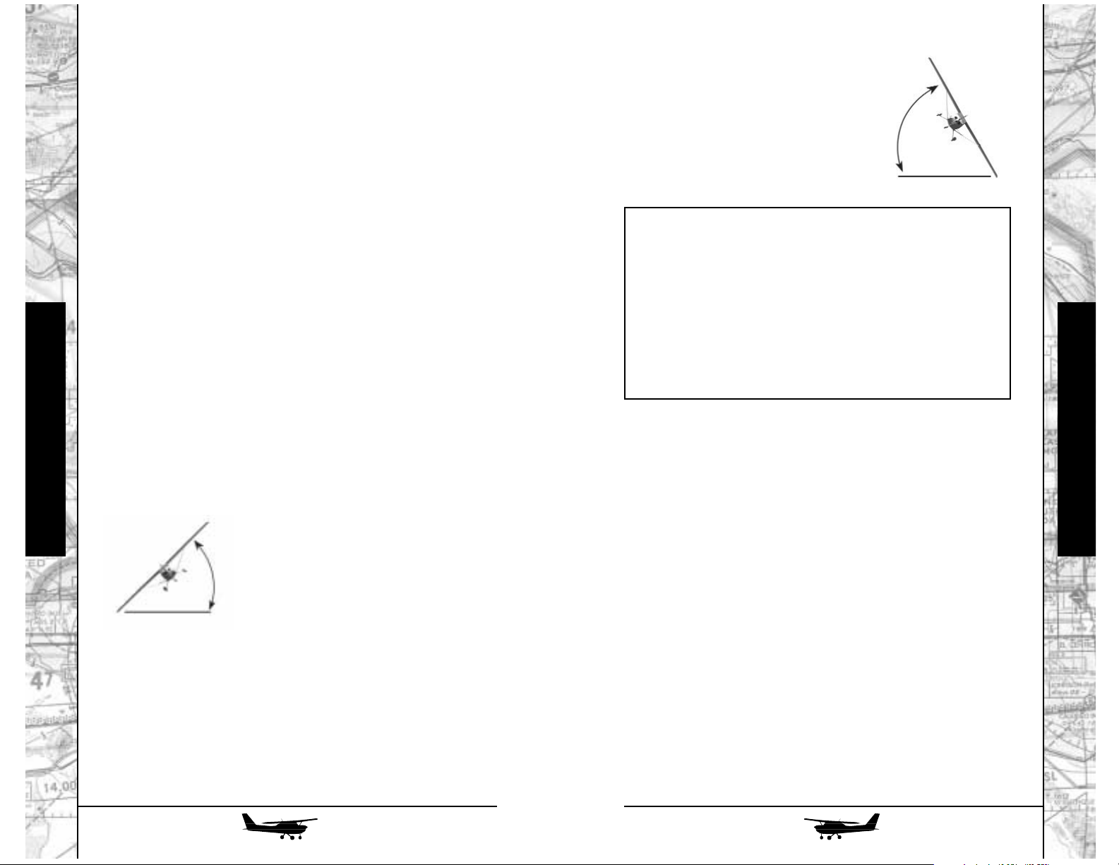
118
119
The moral to this story? If you ever
find yourself in a spiral, with the airspeed
increasing and the altimeter unwinding at
an alarming rate, there’s a definite onetwo-three sequence to recovery, just like
for a spin. This works equally well
whether you can see out or not:
Where might this come in handy? Well, we found ourselves
in spiral dives at the end of our spin recoveries a little while
ago…but a more likely scenario for a spiral would be if you “let
the airplane get away from you” while flying on instruments.
“OH, SAY, CAN YOU SEE?”
or “Well, no, actually, I can’t…”
Typically, you’ll rack up a hundred hours or so of flying time
before you start considering serious instrument flying. In the long
run, you’ll probably find the sought-after Instrument Rating your
real “ticket to fly,” since without it even the best airplane is a fairweather friend at best. Moreover, for most private pilots, their
instrument flying is what we could call “soft,” or “easy,” IFR. For
example, a couple of minutes of instrument flying right after takeoff can have you up in the sun, above the clouds and on your way,
while your non-rated brethren wait hours for the clouds to burn off
- and, chances are, by the time you get to your destination, the
weather there will be okay. If not, of course, you can make an
approach, since anyone who gets an instrument rating is trained
and tested to the full requirements.
BANKING AND YANKING, PART 3
…and that brings us to the final “hairy” maneuver for the
course. It’s another one with a colorful name from the 1920s:
“The Graveyard Spiral.” (Ominous music, please…)
Back in the days before gyro instruments, airplanes that flew
into even innocuous, non-turbulent clouds often came out in
pieces. Those pilots who survived (“I always use Maxwell House
parachutes…they’re good to the last drop!”) reported being
unable to tell whether they were flying straight or in a turn, then
losing control of the airplane. The airspeed would build up to
awful values (often “off the dial,”) then they’d feel huge forces pinning them into their seats until the hapless airplane started shedding its wings…
A quick demonstration will explain. As usual, get the airplane set up in cruise at a reasonable altitude. Start a reasonably
steep turn, either way, but keep it less than 45 degrees. With the
turn established, add more back pressure and watch the airspeed
indicator, altimeter, and VSI: airspeed will decrease, altitude will
increase, and the VSI will show a climb.
Level out, and roll into a turn the other way - but this time
let it get steeper than 45 degrees - in fact, up to 60 degrees if you
want. Again, add back pressure and watch the gauges. This time,
the rate of turn increases - but airspeed either stays where it is or
increases, too, while the altimeter and VSI show a rapid descent.
A glance at this diagram shows what’s
happening: Remember, the lift produced by
the wing is used both to support the airplane, and to make it turn. As long as the
bank angle is 45 degrees or less, the lift is
pointed “more up than sideways,” so
increasing angle of attack, while it may
make the turn tighter, also makes the airplane climb and slow down.
At angles of bank of more than 45 degrees, however, the lift
is pointed “more sideways than down,” so increasing it does a lot
more to tighten the turn than to make the airplane climb. Moreover,
once in a steep bank, an airplane will tend to steepen the bank
even further. Those old pilots, not knowing “which way was up,”
would instinctively pull to reduce airspeed - but, instead, they’d
just wrap the turn up, tighter and tighter, until something broke (or
they spiraled down into the ground).
Flight Instruction
Flight Instruction
ONE: Reduce power!
TWO: Get the wings level. If you can see the real hori-
zon, great. If not, use the artificial one - or if you
don’t have that, the turn coordinator. If the airplane
isn’t turning (little airplane in the turn coordinator
level), the wings must be at or near level.
THREE: Now - and only now - use back pressure to reduce
the airspeed.
45° bank
60° bank
Page 61
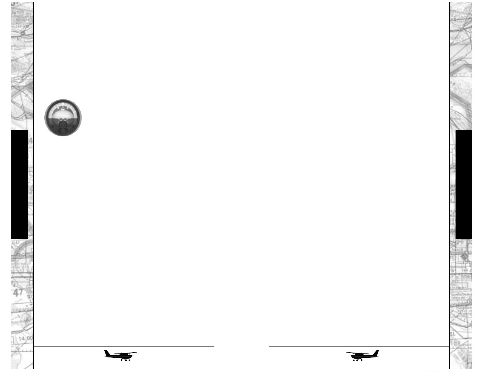
120
121
Keep checking back to the gyro horizon to monitor your
bank and pitch attitude, but cross-check the directional gyro. As
you approach your reciprocal heading (or as your original heading gets down to the 6 o’clock position), gently roll wings level.
Your altitude and airspeed will probably have wandered off a bit;
this is a good time to correct them.
Let’s try a gentle descent. At this stage of the game, you
might want to consider making as few changes at a time as possible, so if you only need to go down a few hundred feet, just apply
gentle forward pressure until you get there, accepting the minor
increase in airspeed; then level off and let the airplane find its way
back to trim speed in its own time.
Let’s say, however, that you find yourself trapped on top of
an overcast; you’ve confessed your plight to a Flight Service
Station, and they’ve informed you that if you descend on a given
heading, you’ll have visual conditions beneath the clouds.
Get the airplane stabilized, in cruise, on the desired heading. Now, simply reduce power a couple of hundred RPM; the airplane will start a gentle descent without your having to fiddle with
the trim. About 100 feet or so above the altitude at which you
want to level off, gently bring the power back up to its original setting. Let the airplane level off and find its own trim speed once
again, then make small corrections as necessary.
As you become more proficient, you can start combining
climbs and descents with gentle turns. We’ll leave more advanced
procedures for future lessons.
THE TECHNIQUE OF LAST RESORT
“A little knowledge is a dangerous thing.” Many non-instrument rated pilots who’ve come to grief have done so because
they’ve tried to do too much and “gotten in over their heads.”
Although it’s not taught all that often anymore, here’s a technique
for a letdown through the clouds to better weather below. Ideally,
of course, you’ll have a full panel of instruments…but the beauty
of this technique is that it’s simple enough for a non-instrument
pilot to accomplish with nothing more than a turn coordinator. In
fact, if the air’s not too rough, you can do a creditable job with
nothing more than the magnetic compass!
For the moment, though, we’ll just look at the very basics:
flying the “four fundamentals” without visual reference.
Let’s start out, as usual, with the airplane in normal cruise at
5000 feet. In actual flight training, instrument students wear a
gadget called a “hood,” or special glasses called “foggles,” that
have the effect of blocking the outside view while still letting them
see the instrument panel. In FLY!, it’s much simpler: just hit Shift
+ I to activate the IFR hood.
Your primary instrument for aircraft control is the
artificial horizon, with its miniature airplane. The
little airplane’s wings should be exactly on the
horizon when the airplane is in level cruise. If
they’re not, use the knob at the bottom of the
instrument to adjust them. You should find straight
and level flight pretty easy: just hold the “picture.”
Attitude control may seem a little more touchy
when you can’t see over the nose, but that’s an
illusion: nothing has changed outside the airplane.
It’s when you start to make a turn that it gets more interesting: you’ll find that many of the things you’ve been doing instinctively, like holding a little back pressure in a turn, now require
conscious thought and correction. Continue to pay attention to
the artificial horizon, but not exclusively. “Locking in” on one
instrument is a sure way to let the others start wandering off.
Instead, develop a “scan,” always returning to the artificial horizon, but checking the airspeed, altimeter, turn coordinator, VSI,
and gyro compass as well.
The most useful maneuver if you inadvertently fly into
“instrument meteorological conditions” (IMC) is a quick 180 to
get back out of them. No, make that a gentle 180 - one of the
fastest ways to get into trouble is to try rapid maneuvers on the
gauges. First, note your current heading on the directional gyro.
Watching the artificial horizon, bank gently in the direction you
want to go - 15 or 20 degrees should be plenty. Don’t blindly add
back pressure, but keep an eye on the altimeter (which reacts
quicker than the VSI). If it starts to go down, add just a little back
pressure as the turn progresses. If the little airplane in the turn
coordinator - not the artificial horizon - moves its wingtip past the
white index mark, you’re turning too fast; reduce your angle of
bank a little.
Flight Instruction
Flight Instruction
Artificial
Horizon
Page 62

Before descending into the clouds
Radionavigation Made Simple
1. If you have a gyro compass, turn to the desired
heading. If not (magnetic compass only), turn directly East or West to minimize the compass’s errors and
swinging tendencies.
2. Extend flaps to the first notch; this will make the airplane more stable in airspeed.
3. Set power and trim for a descent of 500 feet per
minute. Check the trim to ensure that the airplane
maintains it “hands off.”
Upon entering the clouds
4. Let go of the controls and fold your hands in your
lap! That’s right - at this point, chances are you’d do
more harm than good, possibly wrapping yourself
into a spiral, if you try to fly the airplane. Instead,
5. Use gentle rudder pressure only to maintain heading.
Don’t try to “nail” it, either; it’s better to let it get off 5
or even 10 degrees than to overcontrol. Just try to even
out the swings. Remember: be gentle!
Flight Instruction
When you regain visual contact with the ground, wait a few
moments to make sure you’re out of the clouds; then take over
and fly normally. This technique works in just about any generalaviation airplane; over the years, it’s saved quite a few lives. Many
pilots are skeptical about it; FLY! gives you the ideal chance to try
it out and prove that it works.
Not that you’ll need it, of course. With the material in these lessons, you have a solid grounding in basic techniques that’ll see you
through the rest of your career - and the rest of the airplanes in FLY!
All the aircraft in this version of FLY! are equipped to utilize
four forms of radionavigation: Very High Frequency
Omnidirectional Range (VOR), the Instrument Landing System
(ILS), Nondirectional Beacons (NDB), and the satellite-based
Global Positioning System (GPS). In this chapter, we’ll look at the
techniques for using the first three of these; a separate chapter is
provided for “the wave of the future,” GPS.
VOR
The VOR system was developed at the close of World War
II. While at present it’s rapidly being eclipsed by GPS, for the
moment it’s still the primary means of aircraft navigation in most
developed countries. VOR provides the pilot with both directional, or bearing, information (“where am I in relation to the VOR
ground station”) and left-right guidance along courses directly
toward or away from the station. A military version of VOR, called
Tacan (for Tactical Air Navigation) provides distance information
in addition to the directional data. In the USA, many such stations
are co-located with VORs and called VORTACs; their distance
information is also available to civilian users. Other stations,
called VORDMEs, provide similar capabilities without the military system. In use, there’s no difference to a civil user between a
VORTAC and a VORDME.
RADIALS AND BEARINGS
To visualize the function of a VOR, imagine a big bicycle
wheel, with 360 spokes, laid horizontally on
the ground. Its hub corresponds to the
location of the VOR station; the spokes,
since they radiate away from the hub,
are called
radials
.
Flight Instruction
122
123
Page 63
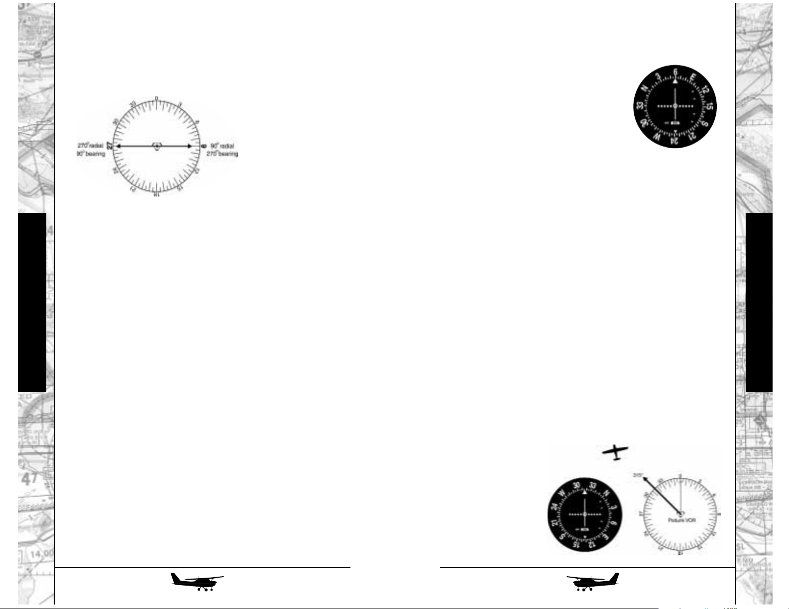
TO, FROM, and the VOR INDICATOR
Let’s look at a typical VOR indicator (discussed in more detail in the Radio Flyer chapter). You’ll notice an outer ring with degree
markings, an adjusting knob at the lower
left, and a needle with a center “target” and
five dots on each side.
Turning the knob rotates the ring to set
the indicator for the desired bearing or radial. If
the needle is centered, you’re exactly on that radial. You’ll notice,
however, that if you keep turning the knob, the needle will center
at two points, 180 degrees apart. One is the radial from the station,
the other is the bearing to the station. How do you know which is
which? By checking the indicator’s TO and FROM flags, which
appear as a white arrowhead pointing up or down, respectively.
POSITION FINDING AND TRACKING:
You can use the VOR two ways: simply to locate your position
(often in conjunction with Distance Measuring Equipment, or DME),
or to follow an exact course directly to or from the station: tracking.
Let’s try the simplest one first. Assume you’re flying somewhere in the vicinity of Podunk and want to find out where you
are. Tune in the Podunk VOR by selecting its frequency on the nav
receiver (see “Radio Flyer”) and look at the VOR indicator. The
needle will most likely be deflected fully to one side or the other.
Turn the knob (called the Omni Bearing Selector, or OBS) until the
needle centers. Now look at the TO/FROM flag. If it shows TO,
continue turning the OBS; the needle will first deflect, then center
once again, this time with the FROM flag in view.
The number at
the top of the indicator, with the needle centered and the FROM
flag in view, is the radial on which you’re currently located.
In this
illustration, we’ve once
again used the example
of the 315 degree radial
from Podunk, so you
know you’re somewhere
to the northwest of the
station.
As we continue to discuss aircraft radionavigation, that term,
as well as its companion, bearing‚ will come up frequently, usually associated with a specific degree value (for example, “the
315-degree radial from Podunk VOR”). It’s important to remem-
ber this simple fact: a radial
always refers to the direction
from the station to the air-
craft; a bearing always
refers to the direction
from the aircraft to the
station. Thus, we can
also say that for every radi-
al, there’s a corresponding
bearing 180 degrees away.
WHAT ABOUT HEADING?
Let’s go back to our bicycle wheel analogy for a moment.
Imagine that each spoke has, engraved in the metal every few
inches, its radial value in degrees, starting with 0 at the north. Let’s
also imagine a literate ant, crawling along and among the spokes.
He can read which spoke he’s on at any given moment - but he
doesn’t have any way of knowing, other than running his head
into either the hub or the rim, which way he’s going on the spoke.
VOR is rather similar: it allows you to directly determine
your location, but provides absolutely no information about
which way you’re pointed (your heading). In this respect, it’s like
GPS, but exactly the opposite of the ADF (Automatic Direction
Finder, which we’ll cover shortly), which can tell you your heading, but has no direct information on your location.
Thus, the VOR might indicate that you are, indeed, on the
315 radial from Podunk - but you’ll have to refer to your magnetic or gyro compass to determine which way you’re pointed (and,
at least in the short term, which way you’re going). VOR stations
are aligned to magnetic north, so when you look at them referenced on a sectional chart they may be rotated so that their 0 radial is rotated towards the Earth’s magnetic pole. Keep this in mind
during flight, since true north does not equal magnetic north in
most cases!
124
Flight Instruction
125
Flight Instruction
Page 64
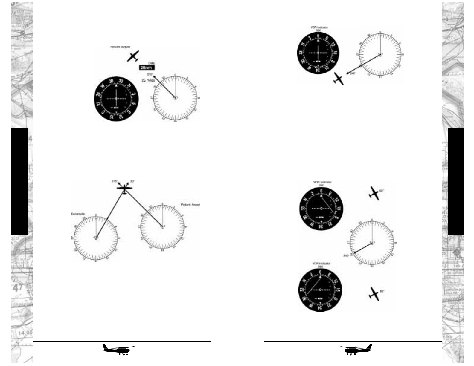
Why “initial” heading? Because, except in the rare case
when the wind is right on our nose (or the even rarer one when
it’s right on our tail), if we simply hold our 060 heading, sooner or
later we’ll be blown off course to the left or right. In either case,
the needle will deflect in the opposite direction, as seen here. The
rule for VOR tracking is simple: when the needle deflects, make a
small heading correction in that direction (“fly to the needle”);
once it re-centers, take out about half the correction, hold the new
heading, and watch the situation for a while.
Don’t “chase the
needle;” make a small heading correction, hold the new heading,
and wait for the needle to respond.
Flight Instruction
Flight Instruction
126
127
If you merely want to determine your exact position, there
are a couple of ways to go about it. If you have DME, just make
sure it’s set to the nav receiver you’re using and read off the distance to the station.
Alternately, you could take a cross-bearing from another
VOR station. Let’s say that Centerville VOR is somewhere southwest of Podunk. Tune your nav receiver to the Centerville frequency and, once again, center the needle with a FROM flag in
view. In this illustration, you’re on the 030 radial from Centerville;
where it crosses the Podunk 315 radial is your exact position.
The more common use of VOR, however, is tracking, using
it to fly directly toward or away from a station. Let’s stick with
good old Podunk once again. We’re somewhere to the west of the
station, and want to fly right toward it.
Once again, turn the OBS until the needle centers, but this
time make sure the TO flag is in view. In this example, we’re on
the 240-degree radial. Since each radial is associated with a bearing exactly 180 degrees away, flying on an initial heading of 060
degrees will take us right to the station.
Page 65

STATION PASSAGE
As you pass the station (right overhead if you’re good or
lucky, to one side or the other if you’re like the rest of us), the needle will quiver a couple of times and the flag will change from TO,
through its striped “barber pole” or OFF indication, to FROM. If
your course takes you onward without a turn, you don’t have to
do anything else. If you’re changing course over the VOR, set the
OBS to the new radial (since you’re now heading away from the
VOR) and continue using the same heading correction technique.
Remember: with the needle centered and the TO flag in
view, the bearing to the station is at the top of the indicator and
the radial from the station is at the bottom. With the FROM flag in
view, the radial from the station is at the top and the bearing to the
station is at the bottom.
Each dot of deflection indicates a deviation of two degrees.
How much is that in the real world? It depends on how far you
are from the station - after all, the “spokes” are a lot closer together near the “hub.” Remember your high school trig? The sine of
one degree is about 1/60 (actually, for those of you working for
extra credit, it’s 0.01745240643728), which gives us the useful
“one in sixty” rule: at 60 nm from the station, one degree equals
about one mile. Thus, if you’re 60 miles out and the needle is
deflected one dot, you’re about two miles off course; at 30 miles,
one dot equals one mile, etc.
The airways depicted on your navigation charts run from one
VOR to another. Typically, you’ll fly FROM the VOR behind you
until you’re about halfway to the next, then retune the nav receiver and fly TO the one ahead. How far out can you receive them?
The FAA has “defined service volumes” for the three classes of
VOR (terminal area, low altitude, and high altitude), but a simple
rule of thumb, if there’s no intervening high terrain, is that every
thousand feet of altitude above the VOR should give you ten nautical miles’ worth of good signal coverage (i.e., at 4000 feet above
the station you should have a good signal at least 40 miles out).
ILS
VOR is used both for enroute navigation and for so-called
“nonprecision” instrument approaches to smaller airports. At larger airports, however, you’ll find a precision approach system
called Instrument Landing System, or ILS. What’s the difference
between precision and nonprecision? Not only is ILS significantly
more accurate than VOR, but in addition to providing left-right
guidance, it also provides vertical guidance along the final
approach glide path. As a result, ILS approaches can be made to
lower weather minimums than nonprecision types - as low as a
ceiling of only 200 feet and visibility of only half a mile, even for
lightplanes, and all the way to touchdown for the latest jets with
fully automatic landing systems.
While ILS uses the same indicator as
VOR, what goes on “behind the scenes”
is quite different (the nav receiver
switches modes automatically when an
ILS frequency is tuned). While a VOR
station provides radials in a full 360degree circle around it, the ILS provides
only a single course, aligned exactly with
the centerline of the runway on which it’s
installed. (During ILS use, the OBS knob and compass ring are not
functional; however, it’s a good idea to set in the inbound ILS
course just as a handy reminder.) While the VOR indicator’s full
deflection represents 10 degrees either side of the desired course,
the ILS’s horizontal guidance component, called the localizer, is
much more sensitive: it’s set between three and six degrees,
depending on the runway on which it’s installed, such that at the
runway threshold full deflection equals only 350 feet off the runway centerline.
The other major component of the ILS is the glideslope.
Essentially, it’s a localizer “turned on its side” to provide precise
vertical guidance down the glide path (set at 3 degrees above the
horizontal at most installations). It’s even more sensitive than the
localizer; at the runway threshold, full deflection indicates only
about 50 feet above or below the correct glide path.
128
129
Flight Instruction
Flight Instruction
Page 66

130
131
Flight Instruction
Flight Instruction
Finally, most ILSs have a couple of
marker beacons
. These
are very small transmitters that send a short-range signal straight
up to activate both audio tones and colored indicator lights on
your instrument panel. The outer marker is generally about five
miles from the threshold. As you cross over it, you’ll see a blinking blue light in sync with a low-pitched “boop, boop, boop”
tone. The middle marker is about half a mile from the threshold,
and it emits a “dit-daahhh, dit-daahhh” signal in sync with an
amber panel light.
The skills you’ll use to fly an ILS are essentially the same as
those for a VOR, except that now you have to do them in three
dimensions (and quite a bit more precisely). Where, before, you
simply watched the “fly left” or “fly right” indications of the VOR
needle, now you also have to follow the “fly up” and “fly down”
(or, more accurately, “descend shallower” or “descend steeper”)
indications of the glideslope needle. Let’s work our way through
a typical ILS final approach.
Once again, we’re at Podunk - in this case, on the ILS for
runway 09 at Podunk Municipal. Approach control is vectoring us
onto the final approach course from the southwest, and we’re at
an altitude of 1500 feet. Since we’re well to the right of the localizer, the needles are telling us “fly left,” and since we’re well
below the glideslope, they’re also telling us “fly up.” We’ll just
continue to hold our assigned heading of 045 degrees and our
assigned altitude of 1500 feet.
Now we’re beginning to intercept the localizer and we’ve
been cleared for the approach. As the localizer needle “unpegs,”
we’ll turn to the inbound heading of 090 degrees, making small
heading corrections as necessary to center the needle and keep it
there. Here, even more importantly than with VOR, it’s vital
to fly
heading, rather than chasing the needle.
At the outer marker, the glideslope is about 1500 feet AGL,
so as we approach the marker the glideslope needle will start
creeping down from its full “fly up” indication. As it nears the center, we’ll adjust aircraft configuration and power to start following
it down. Just as it’s important to fly headings, and not chase the
localizer needle, it’s important to establish a stable rate of descent
on the vertical speed indicator, correcting as necessary with small
changes in power and pitch attitude, rather than “chasing the
glideslope.”
As we continue down the approach, the needles will
become more and more sensitive - make your corrections smaller and smaller to keep pace. At the middle marker, the glideslope
is about 200 feet above the ground - right at minimums, so if you
don’t see the runway at this point, initiate the missed-approach
procedure. A common error, with the runway in sight, is to “duck
under” the final segment of the glideslope. Don’t do it! Just “hold
what you’ve got,” and you’ll touch down about 1000 feet in from
the threshold with plenty of runway left on which to decelerate
and stop.
Page 67
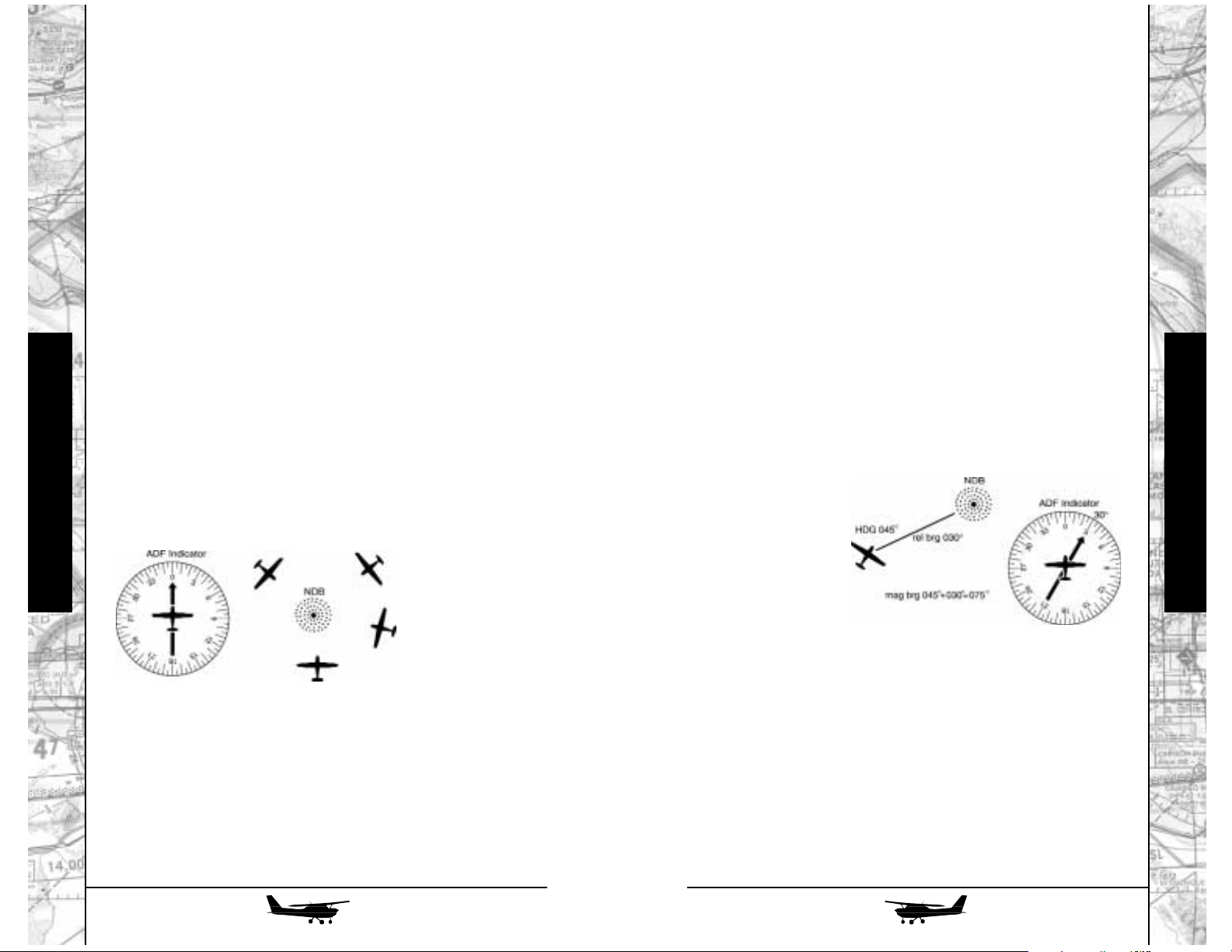
132
133
Flight Instruction
Flight Instruction
THE BACK COURSE
The localizer and glideslope are exactly aligned for use with
only a single runway. At some airports, however, the localizer’s
“back course” can be used for a nonprecision approach to the
other end of the same runway, landing in the opposite direction.
There are only two significant things to remember about such a
back-course approach:
1. Since the OBS is not functional and the localizer provides only
a single course signal, you can’t set the indicator to “work the
other way” as you could on a VOR. Thus, when on the back
course, you must make your corrections by turning away from
the needle rather than toward it. (If you’re lucky enough to
have an HSI - see “Radio Flyer” - you can fly normally as long
as you keep its course arrow set to the front course value.)
2. The back course approach provides no vertical guidance.
Although the glideslope needle may deflect due to local
reflections, these are false signals and must be ignored.
NDBs and the ADF
Your airplane is equipped with a further navigation radio,
called an Automatic Direction Finder (ADF). Actually, this unit is
better described by its old-fashioned name of “Radio Compass.”
Just as a magnetic compass points toward magnetic north, the needle of the ADF will point toward simple ground stations called
Nondirectional
Beacons, or NDBs.
Thus, unlike a VOR,
the ADF can tell you
your heading with
regard to the station,
but not necessarily
where you are.
Note, in this illustration, that each of these airplanes is in a
different location - but the ADF indicator would appear as it is
shown in all of them.
In addition to this ambiguity, the ADF is inherently less accurate than a VOR. In recent years it’s fallen into disrepute, supplanted largely by GPS. In fact, it probably would have disappeared entirely in the USA were it not for its one redeeming feature: in addition to the low-frequency NDBs, it can also receive
(and, for that matter, point at) commercial AM broadcast stations a feature much appreciated on long, boring flights, particularly
during the World Series or NFL playoffs! It’s also still a primary
basis for navigation in the developing world, largely because an
NDB ground station is orders of magnitude simpler, easier to maintain, and cheaper than a VOR.
IT’S ALL RELATIVE
Absent any other information, the only thing you can tell
from the ADF is the relative bearing to a station - starting at 0 if it’s
right in front of you, going to 90 if it’s at your 3 o’clock position,
180 if it’s right behind you, etc. To determine where you are in
relation to the station, and which way you have to fly to get to it,
you need to combine this relative bearing with your current compass heading to get a magnetic bearing. For example, in this illustration our heading is 045 degrees magnetic. The relative bearing
is 030 (the station is 30
degrees right of the
nose), so its magnetic
bearing is 075 degrees
- our heading plus the
relative bearing. That’s
the heading we’d have
to turn to if we wanted
to fly right over the
NDB.
Page 68

134
135
Flight Instruction
Flight Instruction
HOMING AND TRACKING:
The easiest way to get to an NDB is simply to “home” on it:
just turn the airplane until the needle points straight ahead, and
keep it there.
Unfortunately, this won’t give you a straight track across the
ground. Instead, the wind will push you one way or the other. As
you keep turning to keep the station straight ahead, your heading
will change. If you started at any significant distance from the station, you’ll invariably end up approaching the station directly into
the wind.
Instead, determine the
magnetic bearing to the station
by adding the relative bearing to
your compass heading. (If the
result exceeds 360 degrees, just
subtract 360 - for example, if
you’re heading 345 and the relative bearing is 030 for a total of
375, subtract 360 to get the cor-
rect magnetic bearing of 015.) Now turn to the magnetic bearing;
the needle should initially point straight ahead.
Next, hold that heading, and watch the needle. Unless
you’re very lucky, it’ll gradually start to drift to one side or the
other, indicating that you’re being blown off course.
If you were to just turn
until you were pointed right at
the station again, you’d merely
be homing again. Instead, turn
until the needle is as far on the
opposite side of the zero index
as it has drifted. This should
gradually bring you back to the
correct course, at which point the needle will have moved even
farther to the opposite side.
Now take out about half the correction. Continue to fly this
new heading, making further refinements as necessary.
DON’T LIKE ARITHMETIC?
The constant mental calculation of relative and magnetic
bearings has been the bane of ADF flyers for years, but there are
some ways around it.
Perhaps the simplest is to just visualize the ADF needle
superimposed on your directional gyro (DG). If it’s pointing 45
degrees right, for example, just look at your DG and note the number under the 45-degree “tick mark;” that’s the magnetic bearing
to the station.
A small step up in complexity are more modern ADF indicators with a movable, rather than fixed, compass rose. Just twiddle the little adjusting knob to set your current magnetic heading
at the top of the instrument, and read the magnetic bearing to the
station directly from the needle. (You can also read your radial
from the station under the tail of the needle.)
Page 69

Finally, fancier airplanes (including the Malibu Mirage,
Navajo Chieftain, and King Air B200 in this release of FLY!), have
an instrument called a Radio Magnetic Indicator, or RMI, that does
all the work for you. Described in greater detail in the “Radio
Flyer” chapters, it has a compass card that’s automatically synchronized with the airplane’s gyrocompass. VOR signals can also
be displayed on the RMI; thus, at a glance you can see your current bearing to, and radial from, either VOR or NDB stations.
Flight Instruction
Radio Flyer
Part 1
Glance around the cockpit of just about any modern general-aviation aircraft, and the first impression is “there are sure a lot
of knobs and dials.” As you get around to flying the aircraft, you’ll
soon find that there are relatively few instruments you’ll focus on
for guidance in actually maneuvering the machine. Many of the
other instruments, and a lot of the remaining panel “real estate,”
is taken up with the ship’s radio installation - the electronics you’ll
be using both to communicate with ground controllers and other
airplanes, and to locate your position and find your way through
the sky.
Indeed, it’s modern radio equipment that has made even
light general aviation aircraft so useful and practical. Originally,
the radio equipment required for instrument navigation - i.e., finding your way by some means other than looking out the window
at the ground - was so large, heavy, and expensive that only airliners and the largest multi-engine corporate aircraft could use it.
Now, with lightweight, transistorized equipment that can be
mounted right in the instrument panel (instead of in big remote
equipment racks), even the lightest single can have navigation
and communication capabilities surpassing those of airliners of
just a few years ago.
Flight Instruction
136
Much of today’s radio equipment is somewhat standardized;
while the appearance and some features of different manufacturers’ radios may differ slightly, just about all general aviation radios
1
are 6
/4inches wide, so they’ll fit in the standard radio “stack” in
the center of the panel. All the piston-powered aircraft in this version of FLY! use the excellent radios from the Bendix-King division
of AlliedSignal, and they all have the same basic installation, even
if some use different indicators. In addition, the Cessna 172R has
room for its entire complement of radios in a single tall “stack,”
while those in the Malibu and Navajo Chieftain are divided into
two shorter ones.
137
Page 70
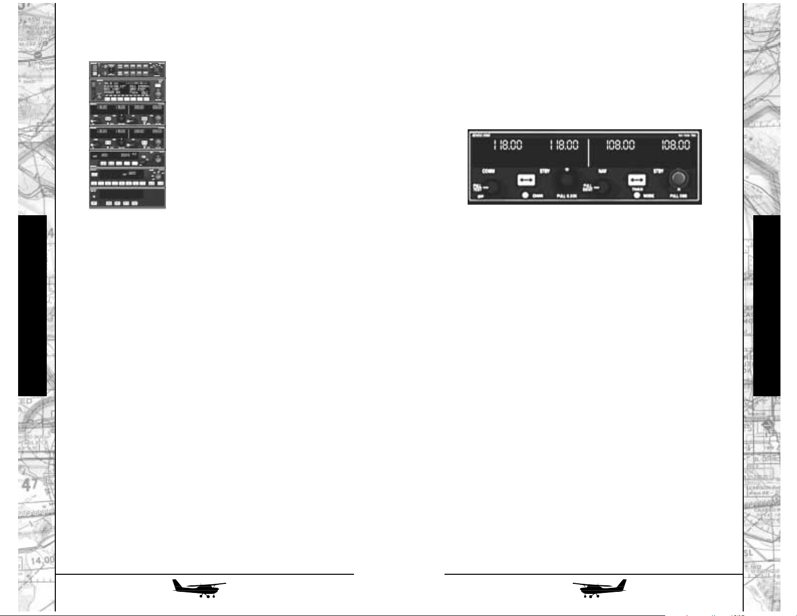
139
To use your prestored channels, press briefly on the “chan”
button. The inner tuning knob will now scroll through the preset
channels, displaying them in the standby frequency window.
When you reach the one you want, press the double-arrow transfer button to make it active.
VOR NAVIGATION
The right side of each KX-155 is the “nav” side, and while it
operates in conjunction with a separate nav indicator in the panel,
it can also display navigation information directly.
ADVANCED OPERATION
Like the comm side, the nav side of the KX-155 has some
nifty extra features, accessible via the little white “mode” button
below the frequency display.
Don’t want to use the VOR indicator (or, perhaps, it’s in use
by another unit like the GPS receiver, of which more later)? Push
the mode button once, and the standby side of the nav frequency
display changes to an electronic OBS which can be set by pulling
out the inner nav frequency knob, while an electronic version of
the left-right CDI needle appears below it.
You can still change back and forth between the active and
“blind” standby frequency using the double-arrow transfer switch;
and as long as the inner knob is pushed back in, you can tune the
active frequency directly. Tune a localizer frequency, and the letters LOC appear in the OBS area. If the received frequency for
either VOR or a localizer is too weak, the word “FLAG” will
appear and the “needle” of the electronic CDI will disappear.
COMMUNICATIONS
Your airplane is equipped with
two KX-155A “nav-comm” radios. The
name indicates that each radio incorporates both navigation and communications functions; in fact, for all practical
purposes each of these units comprises
two completely separate systems, one
for navigation and one for communications.
The left side of the radio is the
“comm” side. It displays two frequencies: the “active,” the one actually in
use, at the extreme left side of the unit, and the “standby,” or preselected frequency, to its right. In normal use, frequency selection
affects only the standby frequency; the outer knob changes whole
megahertz (mHz), while the inner knob changes the figure to the
right of the decimal in steps of .05 mHz. If you need to tune one
of the more recent “split” frequencies, in steps of .025 mHz, pull
the inner knob out, then turn it.
To make your new setting the active frequency, push briefly
on the double-headed arrow button to the left of the tuning knob.
The standby and active frequencies will “flip-flop;” thus, the former active frequency is now maintained on the standby side in
case you need to change back to it quickly. It’ll be overwritten
next time you make a frequency input.
ADVANCED OPERATION
The comm radio can be preset to store often-used frequencies in a series of preset “channels.” To program these, press and
hold the small white “chan” button for two seconds. The unit will
now display a flashing channel number, indicating that the channel can be programmed.
Select which channel number you want to enter by turning
the inner knob. Then press the double-arrow transfer button; the
standby frequency will flash, and can be changed by using the
inner and outer knobs in the usual fashion. Press the transfer button again to store the frequency and, if you wish, select another
channel to program. When you’re done programming, press the
“chan” button again to return to normal operation and save all the
channels you’ve loaded.
Flight Instruction
Flight Instruction
138
Page 71

140
141
TRANSPONDER
While the transponder doesn’t tell you a whole lot, it tells
the world around you - specifically, air traffic controllers - some
things it’s very important for them to know.
Specifically, it tells the rest of the world two things: who you
are, by the numerical code you set into it; and, since ATC’s radars
see in only two dimensions, how high you are, by electronic
information it gets from your altimeter and transmits to the ground
radars every time they sweep past you (and “interrogate” your
transponder, if you want a fancy technical buzzword).
Its controls are very simple. Transponder codes consist of
four digits, from 0000 (which is never used) to 7777 (also never
used); the archaic computer brains of the FAA can’t recognize any
digit larger than 7. When you’re assigned a specific code by ATC
(typically, as part of an instrument clearance or during a conversation with a controller when you want to enter controlled airspace), just punch it in using the buttons. The “CLR” key can be
considered a “backspace” if you make a mistake.
Of course, often you’ll be flying in visual conditions without
talking to any controllers at all. There’s a standard VFR transponder
code for this, 1200 - and rather than having to punch it in every
time, just hit the “VFR” button and it’ll be set automatically. Often,
the first time you talk to a controller, you’ll be using this code, and
to help pick you out from all the other VFR traffic, he or she will ask
you to “squawk ident.” This makes your blip light up specially on
the screen; to do it, just hit the “IDT” button (which, despite what
your instructor may say, does not stand for “idiot”).
Finally, there’s the big mode selector switch on the right side
of the unit. The “OFF” position - surprise, surprise! - turns the whole
thing off altogether. “SBY” is a standby mode, in which the unit is
powered up but not responding to interrogations. It’s considered
Want to know your bearing “TO” the VOR station without all
that laborious OBS-knob twiddling? Push the mode button again,
and the standby frequency display will change to your current bearing, complete with the word “TO.” Another push and the same
thing happens, except now you see the radial, and, appropriately
enough, the word “FROM.” In either of these modes, if the signal is
too weak, the display changes to a line of dashes.
Another push of the mode button gets you a very fancy stopwatch, which starts counting up as soon as you enter this mode.
To stop it and reset it to zero, hold the frequency transfer button
for a couple of seconds. Subsequent pushes on the transfer button
start and stop the stopwatch.
But wait! There’s more! When you’ve reset the stopwatch to
zero, you can use the frequency knobs to preset times and use it
as a countdown timer, very handy for instrument approaches.
Left/Right click the knob to change minutes. Double click the
knob to toggle minutes and seconds. Left/Right click the knob to
change seconds. Now, pushing the frequency transfer button will
start the timer counting down from the preset value.
A final push of the mode button gets you back to the basic
frequency-select mode. The stopwatch, if running, will keep on
doing so; you can refer back to it any time with four quick pushes on the mode button. Since both the #1 and #2 nav-comm
radios have this feature, you have two separate stopwatches at
your disposal - for example, one might be monitoring how long
it’s been since you took off, while the other might be counting
down to remind you to switch fuel tanks later on.
Flight Instruction
Flight Instruction
Page 72

142
143
ADF (Automatic Direction Finder)
Although the Bendix-King one installed in
our airplanes is a very nice modern unit, the
ADF overall is actually a pretty archaic
piece of equipment, dating from the 1930s.
Also called a “radio compass,” the ADF
can point its needle at any low-frequency
station it can receive. In a sense, it’s exactly
the opposite of the VOR: while the VOR can
show you where you are, but not which way
you’re pointing, the ADF can show you which way you’re pointing, but not necessarily where you are. The ADF indicator has a
movable compass card, which can be set by the knob at the 7
o’clock position. If you set your actual heading at the top of the
dial, the head of the needle indicates the present bearing from you
to the station, while the tail of the needle shows the radial from
the station to you…but if you want it to read correctly, you’ll have
to reset it every time you change your heading.
None the less, it
has its uses. As you get
deeper into the arcana
of instrument flying,
you’ll find approaches
based on non-directional beacons (NDBs), and unless you have
an approach-qualified GPS receiver and an appropriately published “GPS overlay” approach chart, you’ll need the ADF.
Moreover, should you ever lose the services of your directional
gyro (due perhaps to a vacuum failure, or one of the instrument
itself), the ADF can provide a heading reference that’s much more
stable in rough air than the “whiskey compass” up in the windshield.
Last but far from least, among the stations that fall within the
tuning range of the ADF are regular AM broadcast outlets. Not
only does this provide a very simple way of navigating if your destination is a town large enough to have a halfway powerful AM
station - you can also listen to it! Many ADFs in high-performance
airplanes gather dust except during the World Series playoffs or
the Superbowl.
good form to “squawk standby” when on the ground, supposedly
to prevent cluttering up controllers’ scopes around the airport; but
in the real world, their equipment automatically “disappears” any
targets moving at less than flying speed anyway, so you might as
well ignore it. “TST” tests all the functions of the equipment and
lights up all the segments and legends on the display.
“ON” is what you’d expect to be the normal mode, but
they’ve pulled a fast one on you here: since current regulations
require all aircraft to have not only the transponder but the altitude reporting equipment as well, your normal operating mode
will be “ALT.” In this mode, the “raw altitude,” or flight level,
being reported to the ground stations will be displayed on the left
of the transponder.
Note that this will not necessarily correspond to your altimeter reading unless the local pressure is 29.92 in. Hg. and you’ve
set the altimeter accordingly; it could be a couple of hundred feet
off either way if the local altimeter setting is particularly high or
low. (ATC’s computers automatically take this into account). More
likely, the only time you might use the “ON” position is if your
altitude encoding system is way off, in which case the controller
will tell you to “stop altitude squawk.”
You might want to remember a couple of specific squawk
codes, too. The emergency code is 7700, one to punch in anytime
you’re in real trouble (for example, an engine failure or other
inflight emergency). Somewhat less frantic is 7600, the code to
use when you’ve lost radio communications but are otherwise
OK. If you can still receive but not transmit, controllers will often
transmit to you “blind,” asking you to acknowledge by pressing
your “ident” button.
Finally, and relatively unlikely considering that this is a simulator, 7500 is the international code indicating “I’ve been
hijacked, but don’t really want to talk about it right now because
someone is shoving the nasty end of an AK-47 into my ear.”
Flight Instruction
Flight Instruction
Page 73

144
145
GLOBAL POSITIONING SYSTEM (GPS)
It’s really a sign of the times that even the most basic airplane in FLY! - the “lowly” Cessna 172R - now comes with a GPS
as standard equipment. Only a few years ago, GPS was considered a highly exotic (and extremely expensive) system for worldwide navigation, suitable only for the heaviest bizjets. Now that
you can buy a basic handheld version at Wally World for a couple of hundred bucks, it’s also become the de facto navigation
standard for new light aircraft.
There are some very neat things about GPS: since it’s based
on satellites, rather than ground stations, it works anywhere in the
world. And since it’s digital, its remarkable accuracy - within 300
feet at worst, and generally much better - remains the same anywhere you use it. In normal mode, one dot of deviation (either on
the GPS’s own display or on a CDI connected to it) represents one
mile off course, whether you’re a thousand miles from the waypoint or right on top of it.
FLY’s airplanes use the Bendix-King KLN-89 GPS. With the
exception of the 89B extensions, almost all of the system’s features
are implemented in FLY! The displays you’ll find yourself using
most often (and which are implemented here) are the four “NAV”
pages. The first gives you the name of the waypoint you’re flying
to, an electronic CDI, numeric displays of both the desired track
or DTK - the course you should be flying to get to the waypoint and the actual track, the course over ground that you actually are
flying at any given time, groundspeed, and time remaining until
you get to the waypoint.
The Bendix-King ADF used in FLY! has standby and active
frequencies that work exactly the same way as for the nav and
comm radios. It also has a stopwatch that works the same way as
the ones in the KX-155s, so now you have three timers at your disposal - say, one to show how soon you’ll reach the next checkpoint, one to show when to switch fuel tanks, and one to remind
you when to open your brown bag flight lunch. In fact, you really have four, since the ADF also has a flight timer that starts when
you turn on the radio power (in fixed-gear airplanes) or when you
lift off and retract the gear in folding-roller ones. The FLT/ET button switches back and forth between the two timers; in ET mode
(it stands for “elapsed time,” not the little leathery guy who was
always trying to phone home), the SET/RST button starts and stops
the timer or, when held in, lets you preset it for count-down use,
just like the ones in the comm radios.
Flight Instruction
Flight Instruction
Page 74

146
147
One area where you’ll often be entering data is in conjunction with the “direct to” key - the one that has a capital “D” transfixed by an arrow. Hit that key, and the GPS will request that you
enter a waypoint (often your destination airport). Once it’s entered
and and you’ve confirmed it with the “ENT” key, the unit will
automatically switch to “nav” mode and display distance, bearing, and track to that point, whether it’s a few miles away or
halfway around the world. In addition to being displayed on the
GPS itself, the left/right steering portion of the nav display can be
switched to show up on the #1 nav indicator, where it can be
“seen” by the autopilot as well as by you.
Finally, several of the available pages have so-called “cyclic
fields,” blocks of data marked with the caret or “hairpin” (>). This
indicates that you have a choice of what data to display in this
field. To change it, turn on the cursor using the CRSR key, then
turn the outer knob until the desired field “reverses out.” Now hit
the “>CLR” key. The field will change to something else - for
example, from GS (groundspeed) to BRG (bearing). Each successive push of the >CLR key will offer another choice until you’ve
seen all that are available. When you’ve “customized” the display
to your liking, push CRSR again to turn off the cursor and store
your choice.
Don’t panic! There is more detailed information on the GPS
later in the GPS Appendix (pg. 265).
.
AUTOPILOTS, or, “Let George do it…”
It’s another sign of the times that even an airplane as basic
as the 172R has an autopilot - as do all of the airplanes in this
release of FLY! We’ll go into more detail about individual autopilots as we work with each airplane, but, again, we can make some
general statements here that apply to all the systems.
The second nav page shows your present position, both in
latitude/longitude and as radial and distance from a nearby navaid
(usually a VOR or airport). The third page shows present time, the
time you took off, the time you’ll arrive at your final destination,
and how long you’ve been flying. The fourth page is a very simple schematic moving map. In FLY! - alas, not in real airplanes you can also “pop up” an actual FAA Sectional Aeronautical
Chart, complete with a symbol showing your position, by hitting
the “NumLock” key.
There are a few other GPS functions of which you should be
aware. You needn’t bother with the GPS’s flight plan pages, on
which you can enter up to 25 different pre-stored flight plans with
departure, intermediate, and destination waypoints; in FLY!, the
flight plans you set up in the simulator’s Flight Planner are automatically transferred to the GPS. On the other hand, if you ever
get in trouble on a flight and want to get down fast, hitting the
GPS’s “NRST” key will bring up a display of distances and bearings to the nearest airports.
Overall, the system’s functions are easy and interesting to
explore, and use the same conventions for input and output from
one page to another. To move from one page - which you might
consider like a chapter in a book - to another, turn the large outer
knob. A little “dash” at the bottom of the display will indicate
which page you’re in at any time. Within each page are subpages, accessed by turning the small inner knob. The name of the
master page, and number of the sub-page (for example, “NAV 3”)
are always displayed on the left side of the display.
If you need to enter data, hit the “CRSR” key to turn on the
cursor; the affected field will “reverse out,” showing black characters on an orange background instead of vice versa. Now the
large outer knob moves the blinking cursor to the position of any
character you want to change, while the small inner knob scrolls
through the available characters. When you’ve input the correct
information, hit the “ENT” key to enter it. If you make an error, the
key marked “>CLR” works like a backspace.
Flight Instruction
Flight Instruction
Page 75

148
149
In the navigation mode, annunciated “NAV,” the autopilot
will follow the course set in the navigation indicator - whether the
information is coming from a VOR receiver or the GPS. In the
172, the heading “bug” must be set to the same value as the
desired course; in the larger airplanes, this value is set by a second knob on the HSI.
Finally, there are a couple of approach modes. The basic
mode, annunciated “APR,” functions the same way as “NAV,” but
is more sensitive to allow greater precision as the airplane nears a
runway. A modified mode, annunciated either “REV” (for
“reverse”) or “BC” (for “back course”), is used only on a few special non-precision approaches that use the “wrong side” of an ILS
localizer to approach the opposite end of the runway normally
used for an ILS. This mode has the same sensitivity as “APR,” but
reverses its responses to needle displacement since the airplane is
flying “the wrong way” on the approach.
All of these are “lateral modes,” in which the autopilot
guides the airplane from side to side. The airplanes larger than the
172 have autopilots that also incorporate “vertical modes.” The
simplest, already mentioned, simply holds whatever pitch attitude
existed when the autopilot was first engaged. Altitude hold,
annunciated “ALT,” will hold the aircraft at a specific altitude
above sea level - the altitude at which the “ALT” feature was
engaged on the more basic units, while the more sophisticated
autopilots will allow you to preset the desired altitude on an external dial, and can control the airplane to climb or descend, then
level off automatically at the desired altitude.
Last, but sometimes far from least at the end of a long day in
nasty weather, these autopilots, when in “APR” mode on an ILS,
can capture and follow the ILS glideslope on final approach. Fly
up to the final approach fix at the right altitude and with the airplane configured for the descent, and when the “APR CAPTURE”
and “GS CAPTURE” lights come on, just extend the gear, reduce
power if necessary, and wait for the runway to show up in the
windshield; even in the Malibu Mirage or Navajo Chieftain, the
autopilot should be able to get you down as close as 200 feet
above the ground, and within half a mile of the runway threshold,
before you have to take over and land visually. In the Hawker, the
“magic brain” can take you all the way to touchdown.
The 172’s simple autopilot is a “single-axis” system. This
means it can steer the airplane from side to side (using the
ailerons) and even track navigational radios, but control of altitude, climbs, or descents, is always left to the human pilot. The
more sophisticated systems in the Malibu Mirage and the Navajo
Chieftain can control altitude as well, and even execute creditable
ILS approaches, while the top-line systems in the Beech King Air
and especially the Hawker can literally fly the airplane from takeoff to touchdown, regardless of weather.
All of these systems have “lockout” logic that won’t let you
engage them unless they’ve satisfactorily passed their preflight test
on the ground. And while they differ widely in capability, their
various modes (if available) have the same nomenclature regardless of which airplane you’re flying.
The “basic autopilot” mode will hold the airplane’s wings
level (and, in every airplane larger than the 172, will also attempt
to hold the pitch attitude present when the autopilot was
engaged). Even this seemingly simple function can be remarkably
valuable, especially if you’re (a) on instruments and (b) busy - say,
trying to look at a map or tune a radio at the same time. The FAA
feels so strongly about autopilots that they won’t even allow a single pilot to carry passengers for hire in instrument flight conditions
unless the airplane has a functioning autopilot - and during his or
her semiannual check flights, that pilot has to show the FAA that
he or she knows how to use the autopilot in all its modes.
In the 172, the autopilot also provides a valuable backup.
Although its more sophisticated modes depend on the directional
gyro, it can still provide its basic wing-leveling function if the gyro
or its vacuum pumps fail.
In the heading mode, annunciated “HDG,” the autopilot
will hold an actual heading, preselected by setting the “bug” on
the directional gyro to the desired value. On the larger airplanes,
the simple directional gyro is replaced by a multifunction instrument called a Horizontal Situation Indicator (HSI); it’s described
in the next chapter.
Flight Instruction
Flight Instruction
Page 76
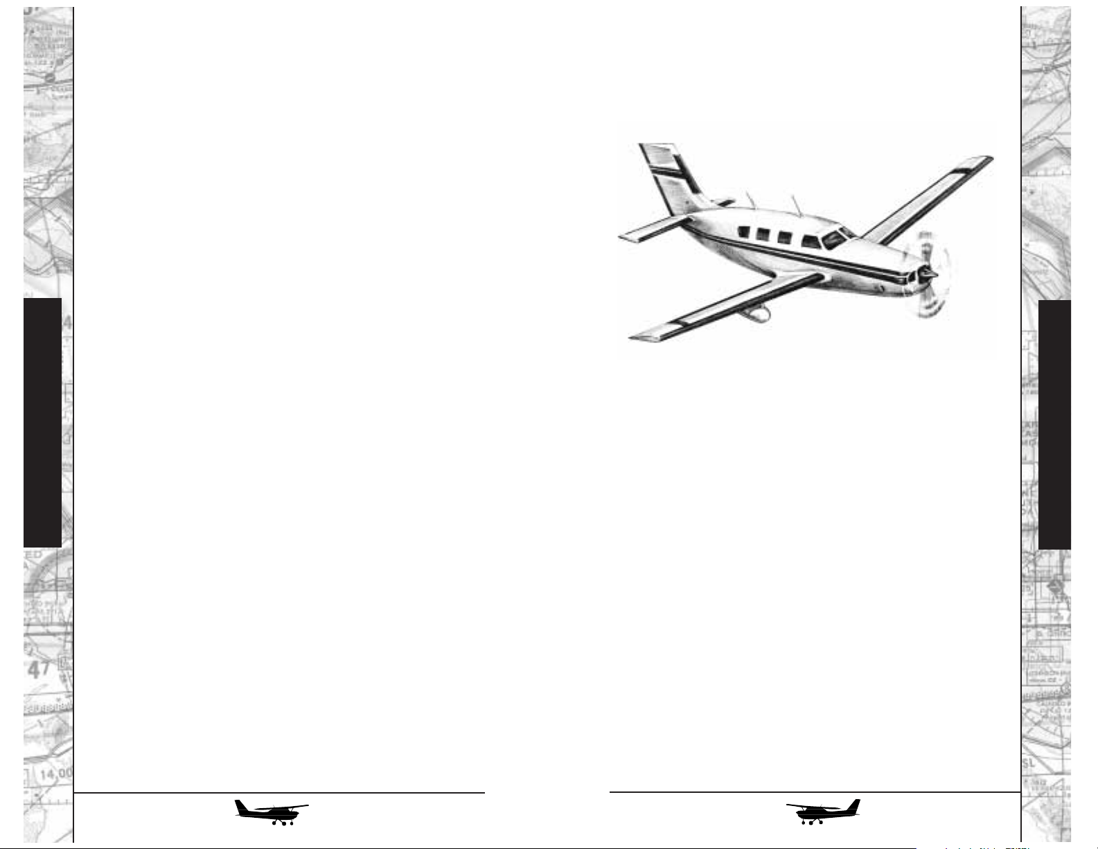
ALL THESE RADIOS…
With this much equipment even in a “simple” 172, you
need some way to select which of the many radios you’ll listen to
and talk over. The gadget that allows you to do this is at the top of
the radio stack, and is called an “audio selector panel.”
Compared to most of the other gear, it’s pretty simple. The
marker beacon receive is particularly important; most ILSs, and a
few other airways and approaches, use very simple low-powered
radio transmitters, pointing straight up, to advise pilots when
they’ve passed a given point. These signals not only produce
audio tones, but light up the blue outer (O), orange middle (M),
and white inner (I) marker lights on the audio panel.
The double row of ten switches selects which of the various
receivers you’ll hear in the headphones or, in FLY!, the cabin
speaker (always selected in the simulator). Pushing any of these
switches so that its little green indicator bar lights up selects that
source to be heard; note that you can listen to as many receivers
at once as you care to. The selector at the right of the panel chooses which transmitter you’ll speak over. In the airplanes in FLY!,
only the COM1 and COM2 positions are active for transmission.
NAV1 and NAV2 can be used to listen to morse code ID of tuned
Navaid and MKR can be used to turn on/off the marker beacon
audible signal.
Flight Instruction
The Mirage: “Every bit as sophisticated...
as business turboprops.”
Piper Malibu Mirage
Flight Instruction
150
INTRODUCTION
If you’re coming into the Malibu Mirage right out of the
Cessna 172R, you’ve covered the entire range of current singleengine airplanes in one grand leap. You’ve gone from one of the
simplest and most basic of all airplanes to the Malibu Mirage: certainly the most advanced and complex single-engine civil aircraft
in current production, and arguably the most advanced in its class
ever built. The Malibu Mirage is every bit as sophisticated, in
terms of systems, equipment, and capability, as business turboprops. Indeed, while we’re concerned here with the piston-powered version, you can even buy a turboprop Malibu Mirage-either the new “Meridian,” right from Piper, or a conversion package for existing Malibu Mirage airframes.
151
Page 77

152
153
WHEN TO RETRACT
The airplane will climb a lot better once the gear is “in the
wells,” but if there’s any chance of its settling back to the ground
- for example, a premature heavyweight takeoff on a hot day - it’s
awfully nice to have those wheels down there! Airline procedure
is for the captain to call for gear retraction as soon as the copilot
verifies, from the altimeter and VSI, that the airplane is climbing
strongly and calls out “positive rate.” Lacking a copilot, we can
use a much simpler criterion, and one particularly useful in case
of an engine failure in this single-engine airplane: leave the gear
down until there’s no longer enough runway ahead to land on,
then retract it. Do not exceed 126 knots airspeed until the gear
has been retracted.
When you move the landing gear handle to the “up” position, a number of things happen. The electrically-powered
hydraulic pump runs, and the amber “HYD PUMP” indicator on
the annunciator panel illuminates. The three green “down and
locked” lights next to the gear handle go out as each wheel
unlocks and begins to retract, and the red “GEAR WARN” annunciator light illuminates. When the gear is completely retracted,
both GEAR WARN and HYD PUMP lights will extinguish. There
are no mechanical uplocks; inflight, the gear is held in the retracted position by hydraulic pressure trapped in the system. In the
event a hydraulic leak or failure allows one or more of the gears
to “bleed down,” the red GEAR WARN light will illuminate.
WHEN TO EXTEND
The simplistic answer, of course, is “before you land,
dummy!” But there’s more to it. In addition to its primary function,
the gear serves a very valuable secondary one: allowing you to
control descents with airplane configuration and drag, rather than
only by power reduction. As we’ll see when we start examining
the engine in detail, rapid, large power reductions are very hard
on the engine; in many cases, it’s better to make only a small
power reduction, achieving the additional required descent rate
by adding landing gear, flaps, or both.
For all that, though, the Malibu Mirage is still a singleengine airplane (albeit, in the eyes of the FAA, both a “complex”
and a “high performance” one); the basic skills you learned in the
172 are entirely applicable to this airplane as well. Even the operating speeds aren’t all that different, particularly in the landing
pattern. True, the Malibu Mirage can cruise at well over 200
knots--but it’s optimized to do so at high altitude, where the indicated airspeeds may be only around 135 knots (this is the reason
for its relatively long, narrow, sailplanelike wings). There are,
however, a number of additional systems to learn about; those,
and their management inflight, are some of the main subject
material in this chapter. In addition, we’ll use the Malibu Mirage
as our platform for further exploration of the arcane world of
instrument flying; and some of its more sophisticated navigational instruments are described in the second “Radio Flyer” section
of this manual.
FOLDING ROLLERS
Obviously, one of the main differences between the Mirage
and the 172 is that the Malibu Mirage has retractable landing
gear. For many pilots, their first flight in a retractable-gear airplane
is a real milestone, their first move into the world of complex and
high-performance machines. Insurance companies, too, seem to
take retractable gear very seriously, at least in terms of how much
experience they want you to have before they’ll turn you loose in
a retractable airplane without adult supervision.
That being said, however, there’s nothing particularly magic
about retractable gear. If you were to forget to retract the wheels
after takeoff, the airplane would fail to realize much of its normal
performance, but there would be no damage to anything but the
pilot’s ego. Forget to extend them before you land, however, and
the results will be considerably more impressive. It’s been said
that there are only two kinds of pilots: those who will someday
make a gear-up landing, and those who have already. It’s also said
that if you’re not sure you’ve landed gear-up (and this may be
more applicable to FLY! than in the real world), a sure clue is that
it will take much more power than usual to taxi.
Basic operation of the gear is about as simple as you can
imagine: retract it after you take off and please, please, extend it
before you land! There are a few fine points, however.
Flight Instruction
Flight Instruction
Page 78

154
155
What if it’s a real problem? Still “no
biggie:” the gear handle will already be
down. Slow the airplane to 90 knots or
less (to make it easier for the nose gear to
extend against the slipstream), then pull
the red emergency gear extension knob
just below and to the left of the normal
gear handle. Don’t be shy--it takes about
a 25-pound pull. This will dump the
hydraulic pressure holding the gear up,
and all three units will extend by gravity
(assisted by springs). Yaw the airplane
from side to side a couple of times to help
the main gear extend and lock. To restore the system to normal
operation, push the emergency control back in, and the gear can be
retracted normally.
PRESSURIZED CABIN
As you’ve seen, the landing gear system is as close to a “nobrainer” as you’ll find on this airplane. The pressurization system
runs a close second. Although the idea of a pressurized cabin may
seem to be pretty heady stuff, it’s nowhere near as complex as it
was in the days of the great piston-powered airliners like the
Constellation, Stratocruiser, or DC-7.
Basically, high-pressure air supplied by the engine’s turbochargers is first cooled, then fed into the cabin. The pressurization system has no control (other than on and off) over the rate at
which this air enters the cabin; instead, it controls pressurization
and cabin altitude by regulating the rate at which the air flows
back out, through a pair of pneumatically controlled outflow
valves at the back of the cabin.
Most of the time, you’ll use only one control: the pressurization controller on the instrument panel. Its outer ring of numbers indicates the altitude, in thousands of feet, at which the system will attempt to maintain the cabin; the inner ring indicates the
highest airplane altitude at which the system can maintain that
cabin altitude. The knob at the lower left controls the rate at
which the cabin altitude climbs and descends; leaving it at about
the 9 o’clock position will provide your passengers with comfortable rates (no “ear popping”).
This can also simplify instrument flying. On a typical
approach using the instrument landing system (ILS), for example,
you’ll be flying level to the final approach fix, then descending
along the glideslope. If you have power set for level flight at a reasonable approach speed with gear up and approach flaps extended, dropping the wheels at the final approach fix will give you just
about the right rate of descent with no additional power reduction--one less task at a time you’re already pretty busy!
You can also use the gear for drag if you need to get down
from high altitude in a hurry--for example, if you have a cabin
pressurization problem while cruising up in the 20,000-feet-andup range. (Bear in mind that the airplane’s oxygen system is only
good for 15 minutes of use.) You can extend the gear at any speed
up to 165 knots; but once it’s down and locked, you can go right
up to 195 knots, only 3 knots shy of the airplane’s 198-knot redline. At that speed, with the gear down, the Mirage will come
down like the proverbial greased piano.
When you select “down” on the gear handle, what happens
is essentially the reverse of the retraction sequence: the HYD
PUMP and GEAR WARN lights come on, and remain on until all
three green lights have illuminated to indicate that their respective
gears are down and locked (the downlocks are integral parts of
each wheel’s hydraulic actuator).
LANDING GEAR WARNINGS
The red GEAR WARN light will also illuminate, accompanied by an annoying horn, to warn the pilot under certain circumstances: any time all three wheels aren’t down and locked
and either (a) the throttle is retarded below about 1/3 power, or (b)
the flaps are extended beyond 10 degrees.
LANDING GEAR MALFUNCTIONS
If you ever lower the gear and don’t see the reassuring glow
of “three greens,” don’t panic. In fact, as any experienced Piper
pilot will tell you, the first thing to check isn’t even part of the gear
system as such: it’s the panel light dimmer switches, below the control yoke. If the DAY/NIGHT switch happens to be in the NIGHT
position, the lights will be on--but so dim you can’t see them!
Flight Instruction
Flight Instruction
Emergency
Landing Gear
Handle
Page 79

EMERGENCY DESCENT
As we’ll cover when we look at the engine, a rapid major
power reduction is hard on the engine--but when you need to get
down, fast, to avoid losing consciousness, it’s no time to scruple.
It’s highly unlikely that the Mirage will be cruising at an indicated
airspeed higher than 165 knots--so pull the power to idle, drop
the gear, and stuff the nose down until you approach 195 knots.
The airplane will come down like a rock; once you’ve gotten the
descent going, you need to fiddle a bit with the fuel mixture to
keep the engine running smoothly. When you get to a “breathable” altitude, level off, retract the gear, and set an appropriate
cruise power.
THE POWERPLANT
Perhaps the most significant difference between the Mirage
and the 172, and certainly the most significant in terms of how
you’ll operate and fly it, is its magnificent turbocharged, intercooled engine and its constant-speed propeller. We’ll address
them first separately, then together:
THE ENGINE
Like the 172, the Mirage has an Avco-Lycoming engine, and
there’s a family resemblance among all the “Lycs.” The 172’s 160hp four-cylinder engine is an IO-360, meaning that it’s fuelInjected, its cylinders are horizontally Opposed, and it has a displacement of 360 cubic inches. Using the same notation, the
Mirage’s 350-hp six-cylinder TSIO-540 is TurboSupercharged,
fuel-Injected, horizontally-Opposed, and has a displacement of
540 cubic inches. Notice the relationship in displacement? Just
about every cylinder Lycoming has ever built since the fall of
Carthage has had a displacement of 90 cubic inches. While there
are differences in detail design, the Lyc boys basically put together engines by adding more and more 90-cu.-in. cylinders, all the
way up to a monster eight-cylinder IO-720.
In this era, when products from computers to hair dryers
have “turbo” modes, it’s worthwhile to take a moment to describe
a real “turbo.” It’s short for “turbosupercharger;” the Mirage
engine has two of them, one for each bank of three cylinders (primarily because two little ones fit better into the cowling than one
big one).
For a normal flight, set the cabin altitude at 500 to 1000 feet
above your takeoff altitude before departure. Once you have
things squared away for your climb, set the controller to 500 to
1000 feet above your landing altitude, or to your cruise altitude
plus 1000 feet on the inner ring of numbers, whichever is higher.
If you’ve had to use this latter technique, reset the controller to
500 to 1000 feet above your landing altitude as you start your
descent.
Just below the controller is a triple indicator showing cabin
altitude, cabin rate of climb or descent, and differential pressure the difference, in pounds per square inch, between the air inside
and outside the cabin. A glance at this will reveal how carefully
the structure of a pressurized airplane must be designed. For
example, assuming that each cabin window has an area around
one square foot, at the maximum normal differential pressure of
4.5 psi, it has to withstand a force of some 650 pounds. Each half
of the windshield has to withstand close to a ton!
PRESSURIZATION SYSTEM FAILURES
There are only two ways the pressurization system can fail:
“not enough” or “too much.”
In the first case, you’ll notice a higher cabin altitude than
what you’ve selected; if the cabin gets much above 10,000 feet,
the CABIN ALT annunciator will illuminate. Check that the controller is set properly, the pressurized air dump valve control is
pushed all the way in, and the PRESSURIZE/DEPRESSURIZE
switch is in the PRESSURIZE position; if that doesn’t cure the
problem, you have no choice but to descend, donning your oxygen mask if the situation warrants.
The “too much” situation is somewhat more insidious, since
there’s no warning light--and how many of us spend a lot of time
looking at cabin pressure in cruise? It’s also highly unlikely, since
even if the pressurization system loses control over the outflow
valves due to some malfunction, the valves themselves will passively vent overpressure at 5.6 psi. Still, a significant overpressure
could pose a real hazard, since it could cause structural failure of
the fuselage.
The cure is easy: pull the pressurized air control to its RAM
position, flip the pressurization switch to DEPRESS--and hang on
to your ears! At this point, the airplane will depressurize very rapidly–as before, descend, donning your mask if necessary.
Flight Instruction
Flight Instruction
156
157
Page 80

158
159
THE PROPELLER
You’ll also have noticed, in the 172, that any time you
changed your airspeed, the engine would speed up or slow down
without your touching the throttle. This is because the 172 has a
simple fixed-pitch propeller. It’s like driving a car with a manual
transmission that’s locked in one gear: the engine speed has a
direct relationship with how fast you’re going down the road.
The Mirage, however, like other high-performance airplanes, has a variable-pitch constant-speed propeller, which is
much more like an automatic transmission. It allows the engine to
turn at the most efficient or appropriate speed for a given flight
condition, regardless of the airplane’s airspeed at the time. For
example, for takeoff, it’s desirable to run the engine at as high an
RPM as possible. This allows the maximum amount of air and fuel
to run through it over time, so maximum power is available.
For climb, a somewhat lower RPM is appropriate. Once leveled off in cruise, the lowest possible RPM that allows the engine
to produce the required level of power is desirable--primarily
because engines and propellers are most efficient (in terms of
miles per gallon, rather than maximum power) at lower RPMs,
and secondarily to reduce both inside and outside noise.
Thus, the Mirage has two main power controls, and two main
power instruments: the throttle, which controls how much fuel/air
mixture gets into the cylinders (and which is set by reference to the
Manifold Pressure Gauge, of which more in a moment), and the
propeller control, which controls the RPM at which the engine
operates, and which is set by reference to the tachometer.
It does this by varying the pitch, the angle at which the propeller blades meet the oncoming air. They’re like the threads on a
screw: in the low pitch, or “high RPM” position, each turn of the
propeller moves the airplane only a little way forward, as if the
“screw” had very fine threads. In high pitch, the “low RPM” position of the propeller control, the blades take a bigger “bite” of air
with each turn, and move the airplane forward faster; the “screw”
is a very coarse-threaded one. I know that the relationship between
high pitch/low RPM and vice versa is confusing at first; the Brits
describe it much more rationally, as “coarse” and “fine” pitch.
Each turbo consists of a turbine and a centrifugal air compressor, linked on a common shaft. The turbine is driven by
exhaust gases, thus powering the compressor to compress the
engine’s induction air, the air supply that will be mixed with fuel
and burned in the cylinders. It’s almost “something for nothing,”
which is why the first turbochargers, in World War II, were sometimes called “bootstrap turbines,” after the legendary Baron
Munchhausen, who claimed to be able to fly simply by pulling
himself up by his own bootstraps.
One reason turbos didn’t appear until World War II is that
they had to wait for the development of sufficiently advanced
alloys. If you could see under the Mirage’s cowling at cruise
power and altitude, you’d find the whole exhaust system, and
both turbos, glowing anywhere from cherry red to a cheerful
orange. Even the compressor side gets pretty warm, which is why
a large intercooler is installed to reduce the temperature of the
induction air before it’s ducted to the cylinders.
Why go to all this trouble? Because, as we gain altitude, the
air gets thinner and thinner; by 18,000 feet, the atmospheric pressure is only half of what it is at sea level. This is both good and
bad: if the air is thinner, airplanes can slip through it with much
less resistance; but there’s also a lot less air for engines to
“breathe,” so they lose power.
With a turbo, however, we can feed the engine “thick” sealevel air, by way of compression, while the airplane slips rapidly through “thin” high-altitude air. A side benefit, in the case of
the Mirage, is that the turbos give us a supply of sea-level air for
cabin pressurization.
You may have noticed flying the 172 that it took more and
more throttle to maintain a desired RPM and airspeed as altitude
increased. I say “may” because most pilots climb the 172 at full
throttle. This is the case with any non-turbocharged, or normallyaspirated, aircraft. The Mirage, however, has an automatic controller that regulates how much exhaust flows through the turbos
to spin them; thus, once you’ve set the throttle for the desired
power setting, there’s no need for further adjustment as you climb
or descend.
Flight Instruction
Flight Instruction
Page 81

160
161
ENGINE OPERATING TECHNIQUE, PART 2:
Mixture Control
There’s a third handle on the power quadrant, with a red
knob. (The 172 has a similar control.) This is the fuel mixture control, which sets the ratio of fuel and air flowing into the cylinders.
How come cars don’t have one? Three reasons: one is that
unless you’re driving in the Andes or the Himalayas, cars operate
over a fairly limited altitude range. Even then, you’ll notice a significant loss of performance driving in the mountains; and, if
you’re going to confine all your driving to higher altitudes, you
can have your car’s carburetor set for a leaner mixture by changing fuel jets.
Another is that modern cars have electronic fuel injection
systems. Somewhere in the bowels of such systems are hundreds
of angels, dancing on the head of a pin to set the fuel mixture
exactly right for the right altitude. But those angels need electricity, and sometimes they get tired, or confused, and you have to
pull over to the side of the road. That’s harder in an airplane. The
manually-controlled Bendix continuous-flow fuel injection system used even on the Mirage’s sophisticated engine is crude--but,
barring contaminated fuel (or the problem, common to all airplanes, of their inability to manufacture more fuel inflight when
needed for longer-than-planned flights), there’s almost nothing
that’ll make it quit working.
Finally, most light aircraft engines are called “air-cooled,”
and, indeed, they are--at cruise power. If, however, their cowlings
and cooling fins were big enough to handle their cooling needs at
takeoff and cruise power, the hapless pilot would have a hard time
seeing past them. Not that it would be much of a problem, since
there’d be so much drag the airplane couldn’t fly, anyway.
Instead, at high power settings, aircraft engines are run at
much richer fuel mixtures than optimum, allowing the excess
unburned fuel to carry away the additional heat. (Pollution? Don’t
even ask...) At high power, they’re not just air-cooled; they’re fuelcooled as well. Car engines, by contrast, can run at much higher
internal temperatures, because they have heavy water-cooling
systems to carry off the excess heat.
Let’s stick with the image of a wood screw a moment longer.
Imagine you’re driving two screws, a coarse one and a fine one,
into the same seasoned block of oak. It’ll take a lot more force to
twist the screwdriver when you’re driving the coarse one; the fine
one will drive a lot more easily, although it will take many more
turns to get it screwed in the same distance.
It’s the same in the air. When you set the prop control (the
blue handle on the power quadrant) for a desired RPM, you’re actually setting a hydraulic governor on the engine that, in turn, meters
oil to the propeller hub to set the blades at the correct angle. If you
increase either airspeed or engine power, the propeller will try to
speed up; the governor will automatically adjust the blades to a
coarser pitch, making the propeller “more difficult to turn,” to
maintain RPM. Similarly, if you slow up or reduce power, the governor will sense the RPM beginning to decrease and will “fine off”
the blades to maintain the correct value. The governor also has
minimum and maximum set points. With the prop control all the
way forward, the engine will run at its 2500 RPM redline if there’s
enough power available; if not (for example, at low power on the
ground), the blades will go to the fully-fine position and will act as
a fixed-pitch propeller. The minimum set point corresponds with
the bottom of the green arc on the tachometer.
ENGINE OPERATING TECHNIQUE, PART 1:
Power Settings and Changes
Power setting for high-performance piston airplanes are
almost always expressed in terms of a pair of numbers: the manifold pressure, or throttle setting, and the RPM, or propeller setting-
-for example, “35 in. Hg./2500 RPM.” What’s an “in. Hg.?” It’s an
inch of mercury, an ancient measure of air pressure dating from
the days when pressure gauges were vertical glass tubes full of
quicksilver. (Does the measurement seem familiar? It’s the same
unit, at least in the USA, that you’ll find for altimeter settings; normal sea-level pressure is around 30 in. Hg.)
The rule of thumb to avoid overstressing an engine (rather like
the “lugging” you feel if you try to drive up a steep hill by flooring
your car in too high a gear) is that when making a power increase,
you increase the RPM first, then the manifold pressure. Power
decreases go exactly the other way: manifold pressure first, then
throttle. As a reminder, you can use the mental image of “Propping
something UP” and “Throttling something DOWN.” (For small
power changes within the cruise regime, you may often find yourself changing only one control without moving the other at all.)
Flight Instruction
Flight Instruction
Page 82

ENGINE OPERATING TECHNIQUE, PART 3:
“Take care of your engine, and it’ll take care
of you.”
Compared to the “bulletproof” normally-aspirated engine on
the 172, the Mirage’s TSIO-540 is a high-strung thoroughbred--after
all, its displacement is only 50% bigger, but it produces more than
twice as much power under very demanding circumstances.
You’d think the enemy of such an engine is heat, but that’s
only part of the problem. The real culprit is temperature change,
especially if it’s rapid--and a lot more aircraft engines are damaged (cylinder head cracking, etc.) by cooling them off too fast
than by overheating them.
This usually occurs during descents: you’ve reduced power,
so the engine isn’t developing as much heat as it was, while at the
same time your airspeed has increased, so that more cooling air is
moving through the cowling. There are, however, several easy
steps you can take to minimize the ill effects.
One, as mentioned before, is to use aircraft configuration
and add drag for descent, rather than simply pulling off the power
and stuffing the nose down at “Warp speed.” It may look weird to
extend the landing gear at 20,000 feet (admittedly, a severe case),
but no one is watching anyway.
Another, and perhaps the most important, is to reduce
power slowly. A pretty good rule of thumb is “don’t pull off more
than one in. Hg. of manifold pressure per minute,” although in a
pinch--say, if ATC wants you to get down “right now”--you can
pull off two inches, then wait two minutes. Try to adhere to this
rule until you get down to about 55% power or less--and keep an
eye on your CHT gauge, striving to keep it at least above the bottom of the green arc.
Finally--and this is the one that most pilots seem to ignore,
especially when they’re new to high-performance flying--don’t be
in any big hurry to enrich the mixture as you descend, particularly
in turbocharged airplanes. If your fuel injection system is working
right, the mixture you’ve used for any cruise power setting will be
adequately rich for that or any lower power setting. There’s no reason to enrich it, which wastes fuel as well as overcooling the
engine, until you’re down near the ground, where you might need
a richer mixture for a go-around or missed approach...and by that
time, you should be configured for approach and slowed up so
there isn’t as much of that nasty cool air blowing over the cylinders.
162
163
You have three instruments to set the correct fuel mixture in
the Mirage: the fuel-flow indicator, the turbine inlet temperature
indicator (TIT), and, to a lesser extent, the cylinder-head temperature indicator (CHT).
Takeoff and initial full-power climb are always performed
with the mixture control in its forwardmost full rich position.
Typically, for a cruise climb, the throttle and prop control are set
for the desired power setting and the mixture is pulled back until
the fuel flow indicator shows the correct value as set out in the
pilot’s operating handbook (for example, 35 in.Hg./2500 RPM/32
gallons per hour).
You can use a similar technique for cruise power setting, but
the handbook values are, of necessity, very conservative. Once at
cruise power, you can set the mixture more accurately by referring
to TIT. It will reach its maximum, or “peak,” when the ratio of fuel
and air is exactly optimized. Piper’s operating handbook authorizes operation at peak TIT for all cruise power settings up to a limit of
32 in. Hg/2500 RPM. How much more efficient is this than setting
by fuel flow? Well, although we’ve only reduced power 3 in. Hg.
from the climb setting, fuel flow has dropped to 20 gph--more than
a third! Another reason that these lean fuel flows are authorized for
cruise, rather than for climb, is that now airspeed is higher, so more
air flows through the cowl to cool the engine.
How do you set it? Get the airplane leveled off and trimmed
correctly for cruise, set cruise power, wait for engine temperatures
to stabilize and then slowly start leaning the mixture while watching the TIT. It will rise to a peak, then begin to drop off again. Note
the peak, and when it starts dropping, enrich the mixture until it’s
back at the peak value.
Flight Instruction
Flight Instruction
Fuel Flow TIT CHT
Page 83
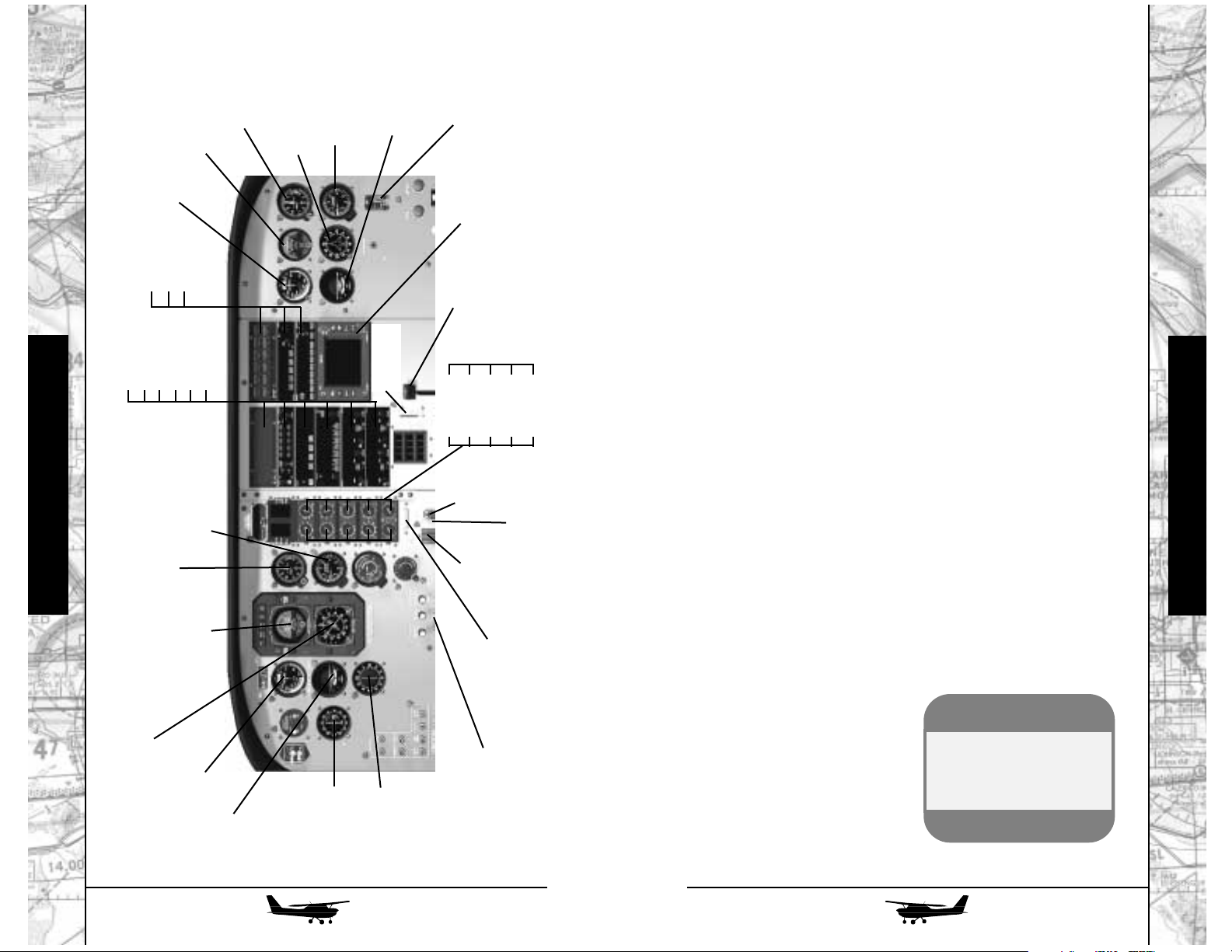
164
165
Flying the Malibu Mirage
Welcome aboard the Malibu Mirage! Settle down in the
cockpit and look around, and it’ll seem at first as though there’s a
lot more going on than in the 172. Sure, there is more, but not all
that much...and, as you start to glance around, you’ll see some
familiar old friends.
SAME OLD “SACRED SIX”
The primary flight instruments are almost exactly the same as
they are in the 172 (in fact, over on the copilot side of the panel,
they are exactly the same). The only difference on the captain’s
side is that the directional gyro has been replaced by an extremely handy device called a Horizontal Situation Indicator (HSI). For
a more detailed description, check the Radio Flyer Part 2. Another
additional instrument, the Radio Magnetic Indicator (RMI) is also
described in that section.
WHAT’S UP
One thing you’ll notice in the Mirage is that some of its most
important electrical switches, including the battery master and the
magnetos, are arranged across the top of the windshield. This is
partly an effort to save instrument panel “real estate,” and partly
an effort to give it a “big airplane” feel, like the overhead panels
you’ll find in an airliner. Even low-time pilots hear the refrain from
“The High and the Mighty” and see those four imaginary gold
rings on their sleeves when they have to fiddle with stuff in the
roof...never mind that by the time a real airline pilot has reached
the eminence where he’s flying something big enough to have a
complex overhead panel, he’s probably so old he needs special
trifocals, with an additional near-vision segment at the top, to
make sense of it!
Flight Instruction
Flight Instruction
CDI/NAV
Pilot’s Airspeed
Pilot’s Turn
Coordinator
ADF
Pilot’s Attitude Indicator
Pilot’s HSI (Horizontal Situation Indicator)
Pilot’s Altimeter
Pilot’s Vertical
Speed
Landing
Gear
Landing Gear
Indicators
Emergency Gear Extension
(Not Shown)
Parking Brake
(Not Shown)
Hottest Cylinder
Indicator
MAP
TITOTCHT
Fuel Qty.
RPM
FF
OP
VAC
Engine Instruments
Annunciator
Audio Panel
Auto Pilot
GPS Panel
NAVCOM1
NAVCOM2
Flap Position
Indicator
Flap Control
Weather Radar
Anti-ice and Environmental Switches
ADF Panel
Transponder
Emergency Locator
Transmitter
Co-Pilot’s Airspeed
Co-Pilot’s Turn
Coordinator
Co-Pilot’s Attitude
Indicator
Co-Pilot’s Gyro
Co-Pilot’s Vertical
Speed Indicator
Co-Pilot’s Altimeter
Mirage Cockpit
SimTip
Use Ctrl and the arrow
keys to look around
inside the cockpits.
Page 84

166
167
DUAL SYSTEMS
While the Mirage has a single engine, it’s a very reliable
one; and if you analyze the history of problems encountered by
single-engine airplanes, it’s often the failure of some ancillary system, rather than the engine itself, that caused the difficulty. Thus,
the Mirage not only has dual vacuum pumps, it also has a multiengine style “split” electrical system, with two completely separate belt-driven alternators on the engine. Circuit breakers are on
the left and right sidewalls, while digital ammeters for each alternator, and a single voltmeter, are on the lower center panel.
Above it, there’s a dual-width avionics stack with room for everything up to, and including, weather radar (its antenna is carried in
a bomblike pod under the right wing).
ENGINE INSTRUMENTS
The Mirage uses state-of-the-art electronically-driven engine
instruments, arranged in two vertical rows
just to the right of the primary flight instruments. These instruments are somewhat
smaller than standard ones, but since they’re
operated electronically, they’re linked with a
digital readout to allow extremely exact readings. Red lights next to each indicator will
illuminate if critical operating limitations are
exceeded, and the extent and duration of
each limitation is recorded and stored.
The digital readout display is at the top
of the engine instrument stack and has left
and right windows, each showing two lines
of data. When the system is first powered up,
the top lines of the left and right windows
show TIT and fuel flow. The two lower lines
show manifold pressure and RPM.
Another big-airplane touch is the power controls: hefty
multi-engine style levers in a center console, rather than little
plungers sticking out of the instrument panel. Since this airplane
has enough power to make holding right rudder in a prolonged
climb tiresome, it has rudder, as well as elevator, trim; both trim
wheels are on the center console.
Flight Instruction
Flight Instruction
Malibu Overhead Switches
(use Ctrl + Up Arrow to see overhead)
Engine Starter
Battery Master
Fuel Pump
Alternator #1
Alternator #2
Landing Light
Taxi Light
NAV Light
Strobe Light
Annunciator Dimmer
Dump Cabin
Pressure
Compass
Left/Right
Magnetos
Malibu Floor Panel
(use Ctrl + Down Arrow to see floor panel)
Throttle
Emergency Gear
Prop Lever
Mixture Lever
Elevator Trim
Position
Elevator Trim
Knob
Rudder Trim
Knob
Induction
Air Selector
Page 85

168
169
Finally, the bottom row has gauges for the left and right fuel
tanks (60 gallons each). Unlike the Cessna, the Mirage doesn’t
have a BOTH position on its fuel selector (located at the bottom
of the instrument panel); it’s up to the pilot to switch back and
forth between the tanks. Maximum permissible imbalance is 10
gallons (60 lbs); if it’s exceeded, the FUEL IMBALANCE light will
come on in the annunciator panel as a reminder to switch tanks.
An easy way to run the fuel system, assuming you’re starting out
with a balanced fuel load, is to take off and climb on the left tank,
keeping track of fuel consumed, then switch to the right one after
you’ve burned 10 gallons (or as soon as the FUEL IMBALANCE
light comes on). This should be right around the time you level off
at cruise altitude; and since the airplane burns about 20 gph at
cruise, you can now just switch tanks every hour and know that
the two tanks will always be within 10 gal or less of each other.
ICE PROTECTION SYSTEMS
Anyone who’s spent the big bucks for an airplane like the
Mirage - a new one will set you back somewhere slightly on the
wrong side of three quarters of a megabuck! - doesn’t just want it
to be a fair-weather friend. Unlike most other singles (even most
high-performance ones), the Mirage can be equipped so it can be
flown legally in known icing conditions. Controls for the ice protection systems are at the top of the right-hand radio stack.
There are four separate systems. Three of them, operated
electrically, can be used as de-icers (i.e., to get rid of ice once it’s
formed), but are better employed as anti-icers, to prevent it from
forming in the first place! The propeller blades are heated electrically, turning on and off on a 90-second cycle; you can monitor
them on the small ammeter marked PROP AMPS. The windshield
heat has HI and LO settings. Two further switches provide heat to
the pitot tube and the stall warning vane on the left wing.
The other system, providing ice protection for the wings and
tail, has to be operated as a de-icing device, i.e., it can’t prevent
ice from forming, but can get rid of it once it has. This surface deice system has rubber “boots” along the leading edges of the
wings and tail surfaces. Once
1
/4to 1/2inch of ice has formed,
pushing the SURF DEICE switch will cause these boots to be
sequentially inflated with air from the output side of the vacuum
pumps, thus cracking the ice off.
The top two circular instruments, reading from left to right,
are the manifold pressure and tachometer. This is logical, since
they’re arranged the same way the power levers are. Also, since
these are the two engine instruments that you’ll be using most, the
lower two digital display windows, directly above these two vital
gauges, are permanently dedicated to them. High-resolution digital readouts of any of the other gauges can be obtained by pushing the button next to the gauge. The readout will appear in the
top window of the appropriate side, while a green light next to the
gauge will indicate which one is being displayed digitally.
The two gauges in the second row are both affected by the
mixture control. From left to right, they are Turbine Inlet
Temperature (TIT) and fuel flow. Pushing the button to the left of
the TIT gauge brings up its fine-resolution digital display in the top
of the left window at the extreme top of the stack. The digital display for fuel flow is a bit more sophisticated. Pushing the button
to the right of the fuel flow gauge brings a digital readout, in gallons and tenths per hour, into the top right window.
However, pushing the “FUEL” button at the top of the stack
will bring up, on successive pushes, how much fuel is aboard;
how long, in hours and tenths of hours, that fuel will last at the
present rate of consumption; and how much fuel has been consumed since takeoff. In the actual airplane, this unit can be preprogrammed with the amount of fuel onboard before takeoff. In
FLY!, the amount is automatically transferred from the fuel loadout you enter on the aircraft setup screen. The other function
available in the top digital display is a readout of outside air temperature (OAT), brought up by pushing the lower button next to
the right window. Accurate knowledge of OAT is important when
calculating true airspeed and correct power settings.
The third row contains the oil pressure and oil temperature
gauges; the fourth, cylinder head temperature (CHT) and the vacuum system gauge. The CHT normally indicates the hottest of the
six cylinders, annunciating which one it is by illuminating one of
a row of six lights just below the engine instrument stack. A switch
marked CHT CYCLE below these lights lets you “step” through the
cylinders manually. The vacuum gauge indicates vacuum in the
system as a whole; if either of the two vacuum pumps fails, automatic valves keep the system running while a legend in the
annunciator panel lets you know which pump has become disinterested in further toil.
Flight Instruction
Flight Instruction
Page 86

170
171
Once you’ve taxied to the active runway, we’ll do a slightly
more complicated pre-takeoff check than we did in the Cessna.
Remember our CIGARS mnemonic? Now we have a similar, but
new, one: CIGAR-TIP.
C
, as before, is Controls. Check for freedom and correct
movement.
I
, as before, is for Instruments: engine instruments reading
properly, with manifold pressure, RPM, TIT, and fuel flow showing in the top digital display; altimeter set; HSI showing the correct heading; and artificial horizon erect and steady.
G
, as before, is for Gas - correct amount onboard, fuel
gauges verified, fuel selector on the fuller tank, and, for the
moment, emergency pump OFF. (We’ll use it as a backup for takeoff and landing, but let’s leave it off during the runup as a check
that the mechanical one is working properly.)
A
now stands for Avionics - considering that this is a complex airplane that will probably often fly in an instrument environment, let’s make sure our nav and comm radios are properly
set before takeoff. For this flight, since we’ll be practicing ILS
approaches, tune to the ILS at the airport you’re using. In addition,
the autopilot won’t engage until it’s run through its self-test cycle
once, so hit its test switch now.
R
stands for Runup, but this time it’s more of a general
reminder to do one; we’re actually going to do it in a bit more
detail a couple of letters further in our mnemonic.
T
stands for Trim. This time there are two to check - both
pitch (at the takeoff mark) and rudder (at its takeoff mark, or a bit
right of neutral). If you have electric pitch trim enabled on your
yoke or joystick, this is a good time to check that, too.
I
stands for Ignition. Set the brakes, and advance the throttle
to 2000 RPM. Check the magnetos one at a time. Maximum
allowable drop is 175 RPM, with maximum differential 50 RPM
between the two. Make sure both are turned back on.
P
stands for Propeller. With the engine still at 2000 RPM,
pull the blue prop control back until it drops to about 1500 RPM,
then return it full forward. On a cold day, you might want to
repeat this (called “exercising the prop”) a couple of times to get
warm oil into its hub.
Note that if you cycle the boots with less than 1/4inch of ice,
you might just “puff up” the ice to the point where the boots cycle
uselessly underneath it. More than
1
/2inch, and the ice might be
too tough to crack off, so you need to keep an eye on it. At night,
the switch marked ICE LIGHT turns on a light on the left side of
the fuselage to light up the left wing leading edge for you. If you
ever notice an inexplicable loss of performance, and you’re flying
in a cloud at any temperature from freezing down to about –20
deg. C, check to see if some of the cloud is sticking to your airplane! (At lower temperatures, any moisture in the air is usually
already frozen before you get there.)
LET’S FLY!
We’re going to make a single, fairly lengthy, checkout flight
in the Mirage - about the same kind of thing you’d get if you were
an experienced pilot being exposed to the airplane for the first time.
Assuming you have little or no retractable-gear or constant-speed
prop experience, we’ll devote a little extra attention to that; and
we’ll finish up with a couple of ILS approaches at San Francisco
International (SFO), one flown by the autopilot and one by you.
STARTUP
The engine starts a bit differently from that of the Cessna.
Check that the fuel selector is in the L or R tank position. When
you turn on the master (battery) switch, you will activate the fuel
booster pump in the selected tank. There’s no separate switch for
these pumps; they’re turned on automatically by the fuel selector.
Crack the throttle about half an inch. Check that the mixture
is pulled all the way aft (idle cutoff); now turn on the emergency
fuel pump. Push the mixture in for about three seconds if the
engine is cold, one second if it’s warm; now pull it back to ICO
(Idle Cutoff) and turn off the emergency pump.
What you’ve just done is primed the engine, allowing a
small amount of fuel to collect in the intake manifold. Now set the
parking brake, check that both magnetos are turned on, and press
the starter. As the engine cranks, the STARTER ENGERGIZED
annunciator will come on. As the engine starts, check that the
light goes out and that the oil pressure starts rising. The gyro
instruments will dance around as they come up to speed. Check
that both ammeters indicate a charge and that no abnormal
annunciators are illuminated. Turn on the avionics master.
Flight Instruction
Flight Instruction
Page 87

172
173
Bring the prop back up to 2500 RPM, enrich the mixture to
about 22 gph, reduce the throttle to around 20-25 in. Hg., and
pull up into a gentle straight-ahead stall. You’ll find the “break” a
bit sharper than in the 172, but there’s plenty of warning from the
stall horn. As you release back pressure to start the recovery,
smoothly bring the throttle up to 35 in. Hg. (that’s why we
advanced the prop and mixture before starting the stall series).
You’ll notice that even with good technique, the Mirage will probably lose a bit more altitude during the stall and recovery; that’s
typical for higher-performance airplanes. Notice, too, that as you
bring in the power, it might take quite a bootful of right rudder to
keep the ball centered.
Here’s an excellent exercise to develop both a good instrument scan, and an awareness of how changes in aircraft configuration affect its performance. It’s called “the FAA Weave,” as it
often shows up during check rides.
Begin by setting the airplane up in normal cruise, trimmed
out to hold altitude “hands-off.” Set the course arrow at your current course, and the heading bug sixty degrees to one side-let’s say
the left. What we’re going to do is make steady turns back and
forth between the course arrow and the heading bug, holding our
current altitude, while changing aircraft configuration and power
setting as required. Roll into a standard-rate turn to the left (i.e.,
turn at a rate so the little airplane in the turn coordinator points its
wingtip at an index mark). When you have the turn established,
extend the first (approach) notch of flaps. Maintain altitude and
allow the airspeed to stabilize.
As you approach the heading bug, roll back into a right turn
and extend the landing gear. Continue to maintain altitude; you’ll
notice that the airplane will slow quite dramatically. Add power,
if necessary, to maintain 100 knots.
By now, you should be approaching the course arrow once
again. Roll back into a second left turn and extend the second
notch of flaps, still maintaining altitude. Adjust power to maintain
90 knots. As you approach the heading bug, roll back into a right
turn, extend the last of the flaps, and-this is the tricky one-adjust
power to maintain 75 knots, while still maintaining altitude.
TAKEOFF AND CLIMBOUT
Taxi into position and line up on the runway. Normal takeoffs in the Mirage are made with flaps retracted. On a very short
field, however, the first notch of flaps will get you off the ground
a bit quicker; we’ll practice that one on our next takeoff.
Make sure that the prop and mixture controls are all the way
forward and turn on the emergency fuel pump. Now, smoothly
bring the throttle up to a manifold pressure of 42 in. Hg. If everything is working properly, that will correspond with the full forward position of the throttle. When the engine is cold, however,
manifold pressure may “overshoot” slightly, requiring a small
adjustment.
Let the airplane accelerate and begin the rotation to takeoff
attitude at 80 to 85 knots. As the airplane leaves the ground, wait
until there’s no longer enough runway to land on, or until you see
a definite climb indicated on the VSI and altimeter; then tap the
brakes and retract the landing gear. Airspeed and rate of climb
will begin to increase at once. Aim for 91 knots until all obstacles
are cleared, then continue to accelerate to 125 knots for a normal
cruise climb. Check that the HYDRAULIC PUMP light has gone
out after the gear has completed retraction.
While the airplane can be climbed indefinitely at full takeoff power, it’s wasteful and noisy. Instead, let’s set cruise climb
power: we’ll gently reduce the throttle to 35 in. Hg., then slowly
bring the mixture back until fuel flow indicates 32 gph. Leave the
prop at 2500 RPM for the moment. Once we’re at a safe altitude
- say, 1000 feet AGL - relax, take a deep breath, and turn off the
emergency fuel pump. Is the airplane in trim? Is the skid ball in
the center? Adjust the trim wheels as necessary.
Let’s level off at 5000 feet for some preliminary airwork. As
the airplane accelerates, set up an economical cruise power of 30
in. Hg. and 2400 RPM. Remember, the throttle is reduced first,
then the RPM. Set the mixture for a fuel flow of about 18-19 gph.
Now try a couple of steep turns. You’ll notice that the airplane isn’t quite as “nimble” as the 172; control pressures are
higher, and the roll rate is slower. Try to get a feel for the amount
of back pressure required. Let’s consider these clearing turns, as
well, and we’ll try a couple of stalls.
Flight Instruction
Flight Instruction
Page 88

174
175
The airspeed will ultimately stabilize somewhere around
145-150 knots, depending on air temperature. That may not seem
all that fast for this airplane, but remember-that’s indicated airspeed. At this altitude, true airspeed should be around 220 knots;
that’s better than 250 mph!
Note, however, that the fuel flow is still pretty high; if you
punch up the “hours remaining” display, you’ll notice that we
don’t have much time to enjoy our high speed. This is where leaning the mixture helps a great deal. We’re probably starting out
with a fuel flow close to 30 gph. You can bring the mixture control back smoothly, but fairly quickly, until we get down to about
22 gph.
From here on, however, you’ll need to continue to lean
slowly and carefully, while watching TIT closely (make sure you
have it showing in the upper left digital display, if necessary by
pushing the button next to the TIT gauge). The system needs some
time to respond. As you continue to lean, the TIT will increase,
then start back down. This is the “peak,” and as it starts down
you’re on the lean side, which is not authorized for continuous
operation. Slowly re-enrich the mixture until it’s once again
reached its peak value-in fact, you may want to continue until it
just barely begins to decrease again, just to be sure you’re back on
the rich side.
Now look at the fuel flow. It should be down around 18 gph.
That’s a 40% reduction in fuel flow-or a 40% increase in range.
Looked at differently: the range figures in the pilot’s handbook are
based on proper leaning procedure. If you’ve planned and fueled
for a 1000-mile flight, and forget to lean, somewhere around 600
miles it’s going to get awfully quiet up there...
Before we head back down, let’s disengage the autopilot
and hand-fly for a moment. Compared to the 172, you may think
that the Mirage is sensitive in pitch: it’ll seem quite difficult to
hold altitude smoothly. Actually, it’s fairly heavy and stable in
pitch. What you’re seeing, instead, is the result of its significantly
higher cruising speed: it takes much less of a pitch change at these
speeds to cause a significant rate of climb or descent. The little dot
at the center of the artificial horizon is the same size as the horizon line on the instrument. You may find that your corrections are
limited to half, or even one quarter, the diameter of that dot.
As you approach the course arrow this time, start reversing
the entire sequence. On your first left turn, retract one notch of flaps
and accelerate to 90 knots, without losing any altitude; on the second turn, bring up the next notch and accelerate to 100 knots; on
the third, retract the gear; and, on the fourth, retract the final notch
of flaps and accelerate to cruise speed once again. Not easy, is it?
In one exercise, you’ve practiced just about all the basic airplanehandling skills you’d need to fly an instrument approach.
UP, UP, AND AWAY
Before we do that, however, let’s make a brief excursion to
altitude to get a look at cruise power setting and mixture control.
Set cruise climb power of 35 in. Hg., 2500 RPM, and 32 gph fuel
flow, and trim the airplane for 125 knots. Note the rate of climbthis thing is quite a performer. However, we’re going all the way
up to our maximum authorized altitude of 25,000 feet, so once
you’ve seen enough of how it handles in climb, go ahead and use
the simulator’s “slew” function to run up to 24,000 feet. Then
return to normal operation so we can make the last 1000 feet of
the climb, and the subsequent level-off, manually.
As we get to about 24,500 feet, bring the nose down just a
bit, so that we climb the last 500 feet at about 500 fpm on the VSI.
As we reach exactly 25,000 feet, ease the nose down until the
altimeter stops moving and the VSI zeros out. Stay ahead of the
trim as the airplane accelerates; it’ll keep on doing so for some
time. Finally, bring the throttle back to 32 in. Hg. and the prop
back to 2400 RPM. (If the engine can’t hold 32 in. Hg. at this
RPM, as might happen on a warm day, increase the RPM, using
the prop control, until it can.)
Let’s use the autopilot for a moment so we can concentrate
on leaning the mixture. Adjust the heading bug to line up right
under the lubber line at the top of the HSI, engage the autopilot,
and hit the HDG and ALT buttons so the airplane maintains its
current heading and altitude. Check the fuel gauges, too-this
might be the right time to switch tanks. If you haven’t changed the
rudder trim since leveling off, the ball is probably displaced a bit
to the left, so dial in just enough left rudder trim to recenter it.
Flight Instruction
Flight Instruction
Page 89
176
177
As the needle moves closer to the center of the instrument,
you’ll notice that the autopilot annunciations change: HDG disappears, and APPR ARM changes to APPR CPLD: the system has
“coupled” to the localizer, the left-right signal of the ILS. Notice,
too, that the airplane has turned so the course arrow is now
straight up and down: we’re flying right at the runway. Depending
on the model autopilot installed, we may also see a GS ARM
annunciator.
By now, the airplane should be stabilized at around 100
knots; adjust power as necessary if it isn’t. Now watch the glideslope needle, which will eventually “unpin” from its position at the
top of the indicator. As it gets within about a dot above the center
index, lower the gear. By the time it’s down, the needle should be
centered. The ALT annunciator will go out, the GS (or GS CPLD)
annunciator will illuminate, and the airplane will start down the
glideslope.
At this point, we’re about five miles from the end of the runway. Speed will have stabilized around 90 knots-the gear added
quite a bit of drag, but we’re also going downhill now! Turn on
the emergency fuel pump. In about two and a half minutes, you
should see the approach and runway lights appearing out of the
gloom ahead. As you approach the threshold, you’ll hear the “ditdah, dit-dah” of the middle marker. Disengage the autopilot, and
as the end of the runway passes under the nose, ease the throttle
to idle, raise the nose to the horizon, and wait for the chirp of rubber on concrete.
LET’S GET DOWN
We’ll head back for the airport for a couple of practice ILS
approaches. On the first one, we’ll let the autopilot handle the
chores so you have a chance to see what’s going on; on the second, you’ll do the flying. If you like, you can set the simulator for
moderately unpleasant weather-let’s say a ceiling of 500 feet and
a mile visibility.
We’ll start a descent manually, so you can get used to reducing power, then slew the simulator so we don’t waste too much
time. Disengage the autopilot, then bring the throttle back just a
bit, reducing power by only one in. Hg, to 31 inches. Check your
watch, or start one of the stopwatches in the nav receivers or the
ADF: it’s a good rule of thumb, on these highly-tuned turbocharged engines, to reduce power at a rate of no more than one
in. Hg. per minute until getting well below the cruising range. This
avoids overly rapid cooling of the engine. What if ATC needs you
to descend quickly? Drop the gear and/or the flaps!
In this case, though, we won’t worry about cracking the simulator’s electronic cylinder heads; pull the power back to about
25 in. Hg., get the airplane trimmed for a descent, and put the
simulator in slew mode to get us down to, say, 2000 feet. Place us
about 15 miles from the airport, near but not right on the reciprocal of the active ILS runway (i.e., if we’re going to land on runway
28R, we should be southeast of the airport on about the 120degree radial).
As you exit slew mode and regain control of the aircraft, set
up a low cruise (24 in. Hg./2200 RPM) and engage the autopilot
in HDG and ALT modes. Fly a heading of about 315 degrees. Set
the course arrow in the HSI to 280 degrees and tune the #1 nav
receiver to 111.7 mHz. The center of the course arrow will deflect
to the right, indicating that we’re left of the final approach course,
and the glideslope needle will deflect upward, showing that the
glideslope is still somewhere above us.
Now press the APPR button. The autopilot will annunciate
APPR ARM, indicating that this mode is “armed,” but it’ll continue to follow the heading bug for the moment. Keep an eye on the
HSI. As the needle “unpins” from its full deflection, extend the first
notch of flaps. As long as we’re going to let the autopilot fly the
approach, this is all we need to use.
Flight Instruction
Flight Instruction
SimTip
To cheat by “slewing” the simulation, press the S
key on your keyboard while using the directional
keys to control the aircraft that you are flying. The
longer you hold the arrow key the quicker you
will skew in that direction. Q slews up. A slews
down. Numpad 5 stops the slew motion. Press S
again to exit slew and return to flight.
Page 90

178
179
At the end of 45 seconds, start a standard-rate turn to the
right. Continue the turn for one minute, or until the head of the
course arrow is 45 degrees to your right (there’s a handy index
mark on the HSI at that position). Your position, if you need to
report it to ATC, is now “procedure turn inbound.”
You can set the heading bug to your new heading as a
reminder. This is a good time to start slowing the airplane for the
approach by extending the first notch of flaps. Continue to maintain 1500 feet and watch the left-right needle of the HSI (the center portion of the course arrow).
When it unpins, just keep its upper end under the lubber
line and you’ll find yourself turning smoothly to the inbound final
approach course. Once you’re established, try to avoid “chasing
the needle.” Instead, if the needle deflects to one side or the other,
make a small heading correction in that direction, then hold it
until the needle recenters; then remove half of that correction and
wait to see what happens, repeating the process as necessary.
Continue to scan all the instruments, returning often to the artificial horizon. As the glideslope needle starts down from the top of
the instrument, get ready to lower the landing gear; do so when
the glideslope is about a dot above the center.
Just as you fly a heading, using the HSI needle for corrections, once you start the descent, fly a steady vertical speed
(around 600-700 fpm down, depending on your airspeed), using
the glideslope needle to tell you when to make very small pitch
corrections. The division between earth and sky on the artificial
horizon is called the “horizon bar,” and we’re talking here in
terms of no more than one bar width-often less than that.
Adjust power and/or add more flap as necessary to maintain
your desired airspeed and rate of descent on the glideslope. As
before, when the runway becomes visible, continue to “hold what
you’ve got” until the end passes beneath the nose, then smoothly
reduce power, raise the nose to the horizon, and touch down.
ONE MORE TIME
Taxi back for takeoff. This time, we’re going to fly the
approach by hand. Leave the #1 nav radio set to the ILS, and the
course arrow set to the inbound course.
Let’s try a short-field takeoff, too. Extend the flaps to the first
notch and line up on the runway. Check that the emergency pump
is on and apply full power.
This time, start to raise the nose at 70 knots. You may note
that the left-swinging tendency is stronger at this low speed. As the
airplane lifts off, accelerate to 80 knots and maintain this, while
retracting the gear, until all local obstacles are cleared. Now continue the acceleration; bring the flaps up as the speed passes
through 90 knots; you may have to make a slight pitch change
and trim adjustment. Accelerate to 125 knots and set climb power
of 35 in. Hg/2500 RPM/32 gph.
At 1000 feet, start a right turn to the reciprocal heading of
the ILS, and continue about 15 degrees beyond it. Notice that the
HSI gives you an “at a glance” overhead view of the navigation
picture: you’re off to the side of the ILS (with the center of the
course arrow deflected to your right), closing in on it at a shallow
angle. The head of the course arrow is pointing toward the bottom of the instrument, so you can continue to “fly toward the
needle” even though you’re heading away from the airport,
“backwards” to the ILS. As the needle begins to center, turn left
until the course arrow is pointed straight down. For a very smooth
intercept, just keep the end of the deflected needle on the bottom
of the lubber line, and you’ll automatically make a gentle turn
until everything is centered.
Level off at 1500 feet and set cruise power. We’re now headed outbound on the ILS, and to reverse our course, we’re going to
perform a maneuver called a “procedure turn.” To ensure doing it
far enough away from the airport, wait until the glideslope pointer
has risen all the way to the top of the instrument before starting it.
While tracking outbound on the ILS, set the orange heading
bug 45 degrees to your left. As the glideslope needle reaches the
top of the scale, begin a standard-rate left turn until you’ve lined
up on the heading bug. As you roll wings level at the end of this
turn, start a stopwatch.
Flight Instruction
Flight Instruction
Page 91
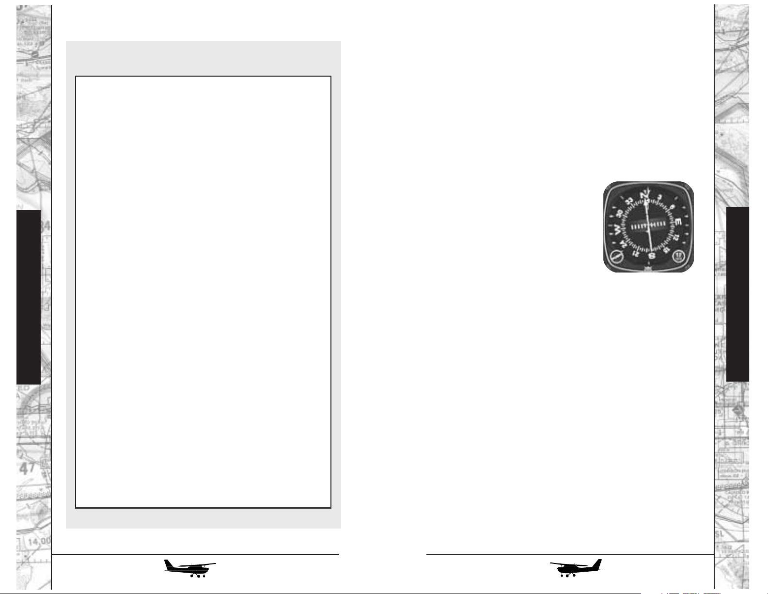
Piper Malibu Engine Run-up and
Radio Flyer
Before Takeoff Checklist
1. Parking brake . . . . . . . . . . . . . . . . . . . . . . . . . . . . .SET
2. Propeller control . . . . . . . . . . . . . . . . .FULL INCREASE
3. Throttle . . . . . . . . . . . . . . . . . . . . . . . . . . . .2000 RPM
4. Magnetos . . . . . . . . . . . . . . . . . . . . . . . . . . . . .CHECK
(max drop 175 RPM, max difference 50 RPM)
5. Gyro suction . . . . . . . . . . . . .CHECK 4.8 to 5.2 in. Hg.
6. Ice protection eqpt . . . . . . . . . . . . .CHECK as required
7. Voltmeter . . . . . . . . . . . . . . . . . . . . . . . . . . . . .CHECK
8. Ammeters . . . . . . . . . . . . . . . . . . . . . . . . . . . . .CHECK
9. Oil temperature . . . . . . . . . . . . . . . . . . . . . . . .CHECK
10. Oil pressure . . . . . . . . . . . . . . . . . . . . . . . . . . .CHECK
11. Propeller control . . . . .EXERCISE, then FULL INCREASE
12. Fuel flow . . . . . . . . . . . . . . . . . . . . . . . . . . . . .CHECK
13. Throttle . . . . . . . . . . . . . . . . . . . . . . . . . . . . . .RETARD
14. Annunciator panel . . . . . . . . . . . . . . . .PRESS TO TEST
15. EMERG fuel pump . . . . . . . . . . . . . . . . . . . . . . . . .ON
16. Alternators . . . . . . . . . . . . . . . . . . . . . . . . . . . . . . .ON
17. Flight instruments . . . . . . . . . . . . . . . . . . . . . . .CHECK
18. Engine gauges . . . . . . . . . . . . . . . . . . . . . . . . .CHECK
19. Pressurization controls . . . . . . . . . . . . . . . . . . . . . .SET
Flight Instruction
20. Fuel selector . . . . . . . . . . . . . . . . . . . . .FULLER TANK
21. Induction air . . . . . . . . . . . . . . . . . . . . . . . . .PRIMARY
22. Ice protection eqpt . . . . . . . . . . . . . . . . .AS REQUIRED
23. Mixture . . . . . . . . . . . . . . . . . . . . . . . . . . .FULL RICH
24. Propeller control . . . . . . . . .RECHECK FULL INCREASE
25. Flaps . . . . . . . . . . . . . . . . . . . . . . . .SET FOR TAKEOFF
26. Trim . . . . . . . . . . . . . . . . . . . . . . . . . . . . . . . . . . . .SET
27. Controls . . . . . . . . . . . . . . . . . . . . . . . . . . . . . . . .FREE
28. Air conditioner . . . . . . . . . . . . . . . . . . . . . . . . . . .OFF
29. Parking brake . . . . . . . . . . . . . . . . . . . . . . . .RELEASED
(check ammeters)
Part 2
The Malibu Mirage and the Navajo Chieftain both use the
same excellent AlliedSignal - Bendix/King radio equipment as the
Cessna 172R. Operation of basic nav, comm, transponder, and
ADF equipment is exactly the same, but the nav displays use more
sophisticated instruments. In addition, depending on airplane,
some additional equipment and capabilities have been added.
HORIZONTAL SITUATION INDICATOR (HSI)
This may well be the coolest single
instrument you’ll encounter. First developed in the 1960s (and called a Pictorial
Navigational Indicator at first), the HSI
combines the functions of a gyrocompass
and a nav indicator (with OBS, CDI, and
flags built right in) to give you a “God’seye-view” that lets you see and interpret
your whole navigation, or horizontal situation at a single glance.
Here’s how it works. The outer ring, calibrated in degrees, is
a gyrocompass. As with the conventional directional gyro, it rotates
as the airplane turns, with your heading always shown under the
line (called the “lubber line,” a throwback to the days of iron men
in wooden ships). Compared to the standard gyro, however, it has
an added feature: you don’t have to set it every ten minutes or so to
compensate for instrument drift. Instead, a small magnetic sensor
mounted elsewhere in the airplane (usually in a wingtip or in the
tail to get it away from all the steel in the engine) constantly corrects
the system for drift, so it points accurately to magnetic north at all
times.
Flight Instruction
180
181
Page 92
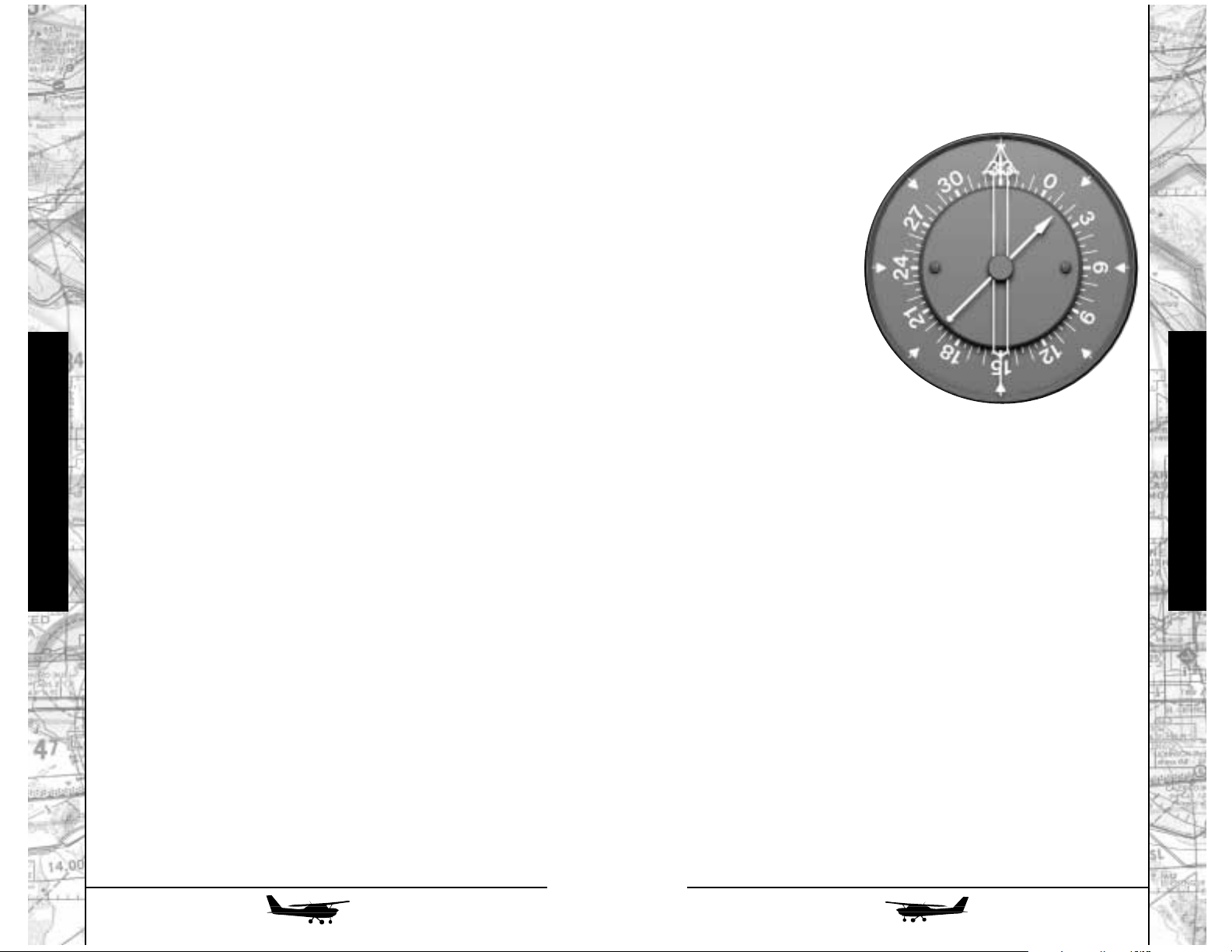
182
183
RADIO MAGNETIC INDICATOR (RMI)
The RMI is the predecessor of the HSI, but it remains a very
handy instrument to have.
You’ll notice that it looks
very much like the ADF indicator in the 172, except that it
has two needles (one of
which has double parallel
lines, just so you can tell
the two apart). In fact, it is
an ADF indicator, among
other things, but with an
important additional feature. Originally, old-fashioned ADF indicators had a
fixed background card, with 0
at the top and 180 at the bottom,
so figuring out your actual bearing to
a station required considerable mental arithmetic. Later ones, as in
the Cessna, have a movable card, but it must still be set manually
to correspond with your airplane’s heading, and changed manually every time you make a turn.
The RMI’s compass card, however, is hooked up to the same
remote slaved gyro system that runs the HSI. Thus, the ADF (single) needle not only shows you where the station is relative to the
nose of the airplane; you can also read off bearing to the station
directly under the head of the arrow, or your radial from the station directly under the arrow’s tail.
The double-needle arrow does the same thing, but it’s
hooked up to a VOR receiver. You’ll recall that the old-fashioned
ADF indicator could show you which way to head to the station,
but not where you were; the standard VOR indicator shows you
where you are with respect to a ground station, but not which way
you’re headed. The RMI gives you both vital pieces of information, regardless of whether you’re using VOR or ADF signals for
guidance.
Some GPS-equipped airplanes have the capability to display
the direction to the next GPS waypoint on the RMI; look for an
appropriately-labeled switch.
In the center of the instrument you see a large arrow called,
appropriately enough, the “course arrow.” This is analogous to the
OBS on a conventional VOR indicator. Like an OBS, it can be set
to the desired course using the knob with the arrow symbol at the
7 o’clock position. You’ll notice that the whole course arrow turns
to indicate the course you’ve set against the degrees on the compass ring. If the airplane turns, the course arrow moves with the
compass ring. Thus, as you look at the instrument, you can see both
the desired course and your present heading in relation to the
miniature airplane portrayed at the center of the dial.
The center section of the course arrow can deflect left and
right, and this is analogous to the left-right CDI needle in a standard
VOR indicator. Next to it, a large arrowhead points forward or
backward; this is the TO/FROM indicator. Inadequate nav signals
are indicated by the orange NAV flag at the top of the instrument.
If you’re right on course, the center of the arrow will be
lined up with its head and tail, and will pass under the little airplane. If you’re off, the needle will move to one side or the other,
so you instantly see where you are in relation to where you should
be, as if you were looking down upon the airplane and your
desired course from a great height.
The knob at the 5 o’clock position sets the orange heading
“bug,” the V-shaped index that can move around the outside of
the compass ring. You can use it as a handy reminder of the
heading you should hold - and the autopilot will do the same
thing in its HDG mode. To fly a desired heading, just set the bug,
engage the autopilot, hit HDG, and the airplane will turn to and
hold that heading.
Whether you or the autopilot (in NAV) mode is watching the
course arrow to keep it centered, you’ll often notice that it doesn’t point straight up and down, but slightly off to one side or the
other. This indicates that you (or the autopilot) are correcting for a
crosswind. The difference between the tip of the course arrow and
your actual heading, indicated under the lubber line at the top of
the instrument, shows your wind drift correction at a glance, so
you see intuitively which way the crosswind is blowing. Are you
starting to realize how cool the HSI is?
Finally, it has one “non-horizontal” mode: when you’ve
tuned the nav receiver to an ILS, you can see a glideslope pointer
at the side of the instrument. Thus, you have the complete navigation picture in one place, simplifying your instrument scan.
Flight Instruction
Flight Instruction
Page 93

184
185
The DME also displays both groundspeed, in knots, and
time, in minutes, until you’ll pass over the station. Bear in mind,
however, that these figures are only accurate if you’re heading
directly toward or away from the station, as you would be when
flying on an airway. If you’re flying some random course, the
groundspeed and time-to-station displays will be inaccurate. In
the extreme case, if the station is directly off a wingtip, groundspeed would be zero and time to the station infinite, regardless of
how fast you’re actually flying.
WEATHER RADAR
I’ve often overheard
passengers, as they board
an airplane and see the
radar screen on the panel,
saying, “Oh, we’ve got
weather radar, so we can
fly through thunderstorms.” Nothing could be
further from the truth: the
whole reason for weather
radar is not to fly through thunderstorms or other severe weather.
In operation, a modern weather radar is very simple. Our
airplane is depicted at the bottom of the screen; the radar scans a
pie-shaped slice of sky, with its outer edge at the range selected
by the pilot. Intermediate range rings and azimuth marks on the
screen help you “eyeball” the position of storms and figure out
how to fly between or around - not through! - them.
All the radar can see is water, in the form of raindrops.
It cannot see clouds as such, and its performance spotting frozen
water (snow or hail) is very poor. Depending on the density of rain
that it sees, it depicts, or “paints,” weather cells in green, yellow,
or red. The assumption, generally a good one, is “the heavier the
rain, the rougher the ride.”
DISTANCE MEASURING EQUIPMENT (DME)
Although it’s gradually being eclipsed (like
most other ground-based
nav aids) by GPS, DME
remains a vital part of the
navigational picture.
Developed in the 1960s
from a military system (still in use) called TACAN, DME provides
the “missing piece” of navigation information not supplied by VOR
or ADF: distance from the station.
It does this by emitting a pulse of radio energy. The DME
ground station receives this pulse and replies to it. By timing how
long it takes to get an answer and calculating in the speed of light
(186,300 miles per second - “it’s not just a good idea, it’s the law!”),
the system determines the range to the station and displays it in
nautical miles and tenths. Almost all DME stations are co-located
with VORs, so by tuning in a single station you can fix your position. (Otherwise, you’d have to tune in two different VORs and plot
where the radials crossed.) In fact, the DME has no separate tuning
controls; there’s a pre-programmed relationship between VOR and
DME frequencies, so if you tune your VOR to a given station, the
DME will automatically tune to it as well.
The small knob in the DME indicator selects which of the
two VOR receivers will command its tuning. A center “hold” position locks the DME onto its current frequency. This can be very
handy if, for example, you’re shooting an ILS (“they shoot ILSs,
don’t they?”) to an airport that also has a VOR located on the field:
first, tune in the VOR so the DME locks in on its signal. Now, put
the DME in “HOLD” mode; then tune the VOR to the appropriate
ILS frequency. You now have left-right and up-down ILS data displayed on your nav indicator or HSI, while the DME reads distance to the airport. (At some larger airports, the ILS has its own
DME facility, making the hold procedure unnecessary.)
A couple of cautions: since the DME reads actual distance to
the station, what it displays is slant range. Unless you’re flying at
recklessly low altitudes, it’ll never read zero, even if you pass right
over the station; it’ll show your altitude, in nautical miles (1
nm=6078 feet). If you’re close to the station, but at high altitude,
“your mileage may vary.”
Flight Instruction
Flight Instruction
Page 94

186
187
THREE-AXIS AUTOPILOT
The autopilots in the Malibu Mirage and Navajo Chieftain
are very similar in basic operation to that in the Cessna 172, but once again - they offer additional features and capabilities.
The most significant of these is that they can control the elevator as well as the ailerons. There are three pitch modes. When
the autopilot is first turned on, it will capture and hold whatever
pitch attitude exists at that time. You can change its pitch attitude
using two methods: either hold the pitch control switch on the
autopilot controller in the up or down position, which will change
pitch attitude at around one degree per second or push the pitch
sync switch on the yoke (if you have it enabled), fly the airplane
to a new attitude and release the switch.
Pressing the ALT button will “capture” the altitude at that
moment. The airplane will level off and continue to hold that altitude. Fine corrections (for example, when you receive a new
altimeter setting and change the altimeter) can be made using the
up/down switch; the airplane will climb or descend at around 500
fpm as long as the switch is held, and will capture the altitude at
which the switch is released.
You also have a very useful device called an altitude alerter/preselector. Set a desired altitude into it, using the inner and
outer knobs, and as you climb or descend to within 700 feet of
that altitude, it’ll alert you with a chime. Once you’ve leveled off
at the desired altitude, the unit will chime again to warn you if
you stray off altitude by 300 feet in either direction.
If you’re climbing or descending with the autopilot engaged,
pressing the ALT ARM button on the alerter/preselector will have
no immediate effect, but as you reach the desired altitude the
autopilot will automatically switch from pitch hold to ALT HOLD
mode, and the airplane will level off, untouched by human hands.
Finally, if you’re flying an ILS, the autopilot can follow the
glideslope. Put the system in APPR mode to arm this feature. As the
glideslope needle nears the center of the scale (usually, you’ll
approach it from below by flying level in ALT mode), the system
will capture it and control the airplane to the required descent rate.
We can also make a couple of fine distinctions. The gradient between levels of rain is important, i.e., a red area surrounded by wide areas of yellow and green may not be as rough as one
where the surrounding bands are narrow. You can also sometimes
get information about the extent of a storm by using the radar’s tilt
control, which lets it look at weather above or below your cruise
altitude as well as straight in front of you. Tilt too far down, and
the screen will light up with smeary returns from the ground,
rather than from weather. On larger, fancier airplanes, the radar is
stabilized in both tilt and roll with signals from the autopilot gyros.
On smaller ones, you’ll have to adjust the tilt manually if you
change pitch attitude for a climb or letdown; and during turns,
one whole side of the screen will light up as the beam scans down
onto the ground on the inside of the turn.
The radars on the Malibu Mirage and the Navajo Chieftain
have an extra feature called “Vertical Profile.” It’s activated by the
“track” arrows and the VP button on the face of the radar. Here’s
how it works:
Select a weather cell you wish to examine and press the left
or right “track” arrow. A yellow line will appear on the screen.
Use the arrows to point it at (and through) the center of the weather cell. Now press the VP button. The radar will stop sweeping
back and forth. Instead, it will remain pointed at the selected cell,
and will scan up and down. The screen presentation will change
to show the airplane at the left and a vertical cross-section of the
weather; the numbers at the top and bottom of the screen indicate
heights in thousands of feet above and below your present flight
altitude, not above sea level.
Flight Instruction
Flight Instruction
Page 95

AUTOMATIC TRIM
In order to control the elevator without its servos constantly
holding excessive pressure, the autopilot system includes an electric motor to operate the trim wheel. In addition, when the autopilot isn’t engaged, a switch on the control yoke allows you to
adjust the trim without letting go of the controls. If the autopilot is
engaged, pressing the trim switch will disengage it.
FLIGHT DIRECTOR
There are times when it would be nice to utilize the capabilities of the autopilot’s computer for things like ILS guidance or interception of desired courses, but keeping the human pilot “in the
loop.” For this, there’s the flight director function. Engage it by pressing the FD switch and a pair of “command bars” appear in the artificial horizon (now called the Attitude Director Indicator, or ADI).
Now, selecting any of the autopilot’s guidance modes, but without
engaging it, will cause these bars to move.
As long as you, the human pilot, keep the miniature airplane
in the ADI “tucked in” to the bars, you’re satisfying the computer’s commands. It’s the same computer that would otherwise run
the autopilot; the only difference is that its output signals are going
to the command bars, rather than the control servos, and you’re
providing the muscle to move the controls instead.
Piper’s Navajo Chieftain
Flight Instruction
Even with the autopilot engaged, the command bars provide
a useful reference and confirmation that it’s doing what it’s sup-
Flight Instruction
posed to. Whether you or the servos are flying the airplane,
remember that satisfying the command bars doesn’t necessarily
mean that you’re on course - but if you’re not, you’re doing what
you’re supposed to in order to return there.
YAW DAMPER
While the autopilot doesn’t need to use the rudder to control
airplane direction (aileron control alone is more than sufficient), it
incorporates a third axis, called the yaw damper, simply to keep
things coordinated and the ball in the center. This provides a significant increase in passenger comfort, particularly in long-body
airplanes. The yaw damper is typically turned on just after takeoff,
and off just before landing. This is particularly important if you’re
landing in a crosswind; otherwise the yaw damper will “fight” your
pedal inputs as you level the wings and “kick out the crab.” Turn it
off anytime you’re adjusting the rudder trim, especially in singleengine situations in the Navajo Chieftain.
188
Piper Navajo Chieftain
MOVING UP TO A TWIN
Welcome to the world of multi-engine flying! In a sense,
you’re already getting a head start: most students start out either
in one of the very light (“lite?”) twins like the Beech Duchess or
Piper Seminole or, if they’re lucky, a slightly larger traditional light
twin like the Cessna 310 (remember Sky King’s “Songbird?”),
Beech Baron, or Piper Aztec.
189
Page 96

THE BEN-HUR EFFECT
A simple way to understand this is to imagine that you’re
driving a Roman chariot. If you want to feel like Charlton Heston,
go right ahead - but since we’re discussing an airplane with only
two engines, we’ll trade in the fancy 4-horsepower Formula IV
version he drove in the movie for a simpler 2-hp sports model.
Okay, so you’re thundering along when one of the horses let’s say, the left one - stumbles and goes down. “Whoa, Dobbin!”
you cry, but the right horse keeps charging along while the left
one, still in harness, gets dragged along on his butt. As you can
see from the accompanying illustration the combination of thrust
on the right side and drag on the left side makes the whole assemblage want to turn left*. The same effect occurs in an airplane: the
engine that’s producing thrust pulls its side of the airplane forward, while the engine that’s stopped does not.
FEATHERS IN THE WIND
In fact, if an engine does quit, the initial effect is even worse
than we’ve shown above, with one engine running and one
stopped. As you’ve noticed flying singles, when you close the
throttle, the engine doesn’t quit turning; if you’ve been brave (or
foolhardy) enough to either cut the mixture or shut down the ignition inflight, the engine still turns, or “windmills,” at a pretty fair
fraction of its former operating speed.
190
191
You, however, are privileged to jump right into the Piper
Navajo Chieftain, and this is a pretty significant airplane in a couple of different ways. Not only is it a prime example of the “medium piston twin” that’s become a mainstay of corporate and light
commuter aviation; it’s also the first “truly professional” airplane
for many pilots, a springboard to an airline career. Piston-powered
it may be, but the Chieftain is a good-sized airplane, carrying up
to nine passengers plus the pilot. (That’s the most the FAA allows
without a two-pilot crew.)
Flying a Chieftain is a great way to gain real-world experience, the kind that looks good in your logbook. Ask in the cockpit of any airline jet nowadays, and chances are good that at least
one of the pilots will have served his or her apprenticeship in the
trusty “Navahog.” The airplane remains an essential air service
provider even today. As regional airlines move into turboprops
and even smaller jets, they can’t afford to keep serving the smallest communities. For those markets, particularly in outlying or
sparsely populated regions, the Chieftain remains a real lifeline.
IT’S EASIER THAN YOU THINK
If you’ve been flying a heavy piston single, such as the
Malibu Mirage provided in this release of FLY!, you should have
no trouble transitioning into the Chieftain (or any other light or
medium piston twin). I’m going to let you in on a big secret: as
long as both engines are running, there’s absolutely no difference
between flying a twin and a heavy complex single. (Actually, in
the case of the Chieftain, it’s even easier, as you’ll find out a bit
later when we discuss the concept of critical engines.) If you’re
coming from the Mirage, you’re on familiar territory: the Chieftain
uses almost exactly the same 350-hp turbocharged Lycoming
engine, so you can just consider that you’re flying two Mirages in
close formation.
By the same token, the special skills you have to learn to be
a safe multi-engine pilot are, in fact, single-engine techniques.
The twin flies just like a single as long as both engines are running; it’s when one of them becomes uninterested in further toil
that things become, to say the least, interesting.
Flight Instruction
Flight Instruction
* Notice: No animals were actually harmed in the
preparation of this manual.
The Ben-Hur
Effect
Page 97
192
193
Some light twins used primarily for training have unfeathering accumulators that allow you to get a prop back into its operating range simply by pushing the control back forward; otherwise, you have to attempt to restart the engine to get oil pressure
back to the prop. In the real world, of course, any problem serious enough to warrant feathering in the first place generally
means you should leave well enough alone and get to an airport
as soon as possible.
THE NEED FOR SPEED
How can we counteract this severe yaw and turning tendency when an engine fails? By the use of rudder - often just about
full rudder - against the turn. Look at most twins, and you’ll see
that they have pretty large vertical tails - significantly larger than
those of singles of similar size and weight. Why? To provide
enough “tail power” to overcome the asymmetric thrust of a single-engine situation.
And how do they do this? Obviously, by deflecting the air
flowing over them. The faster we fly, the more effective the tail
becomes, so it’s the designer’s task to size the tail and rudder for the
worst-case situation: with the airplane flying at minimum speed
with one engine windmilling and the other at full takeoff power.
Unfortunately, this requires a fair bit of work, in its purest
physical sense. If you’ve ever tried to hand-start an airplane (Kids:
don’t try this at home without getting thorough instruction, unless
you want to end up with a nickname like “Lefty”), you’ll know that
it takes a real heave. This is because any piston engine is, in effect,
an air pump - and for a propeller to windmill, it has to turn the
attached engine over each piston’s compression stroke. Although
it’s hard to believe, at typical speeds the drag of a windmilling propeller is very close to that of a solid disk of the same diameter!
The only way a twin can keep flying on one engine is to get
the failed unit to stop windmilling as soon as possible. To do this,
the blades on the constant-speed propellers used on twins are
capable of feathering, or turning completely edge-on to the wind.
Once this has been done, they’re no longer trying to turn a dead
engine, and they come to a stop with an immediate (and very welcome) reduction in drag.
This is so important that in the days of the great piston airliners, if an engine failed and its prop would not feather, the standard procedure was to shut off its oil supply in the hope that the
engine would either seize or break its propeller shaft off outright.
It’s a dangerous procedure, with a high risk of structural failure or
fire - but the drag of a windmilling prop is so great, it was considered worth the risk.
To feather a failed engine in the airplanes in this version of
FLY!, the procedure is very simple: simply pull the affected prop
control all the way back. In the actual airplanes, it has to be
pushed sideways, lifted over a gate, or pulled past extra resistance
to avoid feathering a propeller inadvertently. This opens a valve in
the prop governor that dumps all the oil pressure from the hub,
allowing springs and the blades’ centrifugal forces to swivel them
to the feathered position, if the engine is at lower power or off.
Flight Instruction
Flight Instruction
Incidentally: how come the props don’t feather when you shut
down the engine? Because starting an engine with a feathered
prop puts a huge load on it, so there are anti-feather locks that
are engaged centrifugally at and below about 700 RPM as the
engine stops. In a windmilling situation, it’ll be turning faster
than that, so it can feather. On single-engine airplanes, the
locks are simple fixed pins, since there’s no need to feather once an engine quits, you’re on your way to a prompt landing, period! And on some types of turbine, which start quite
differently, the props do feather when you shut them down.
Got all that? There’ll be a short quiz later on…
Page 98
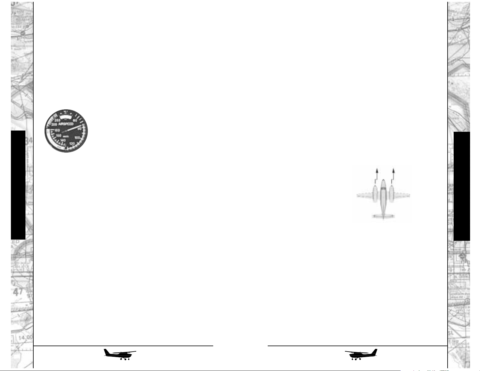
Obviously, there isn’t much point in providing a fin and rudder big enough to keep the airplane straight at speeds below the
stall, since at that point it won’t be flying anymore; instead, the
speed that’s set is called V
MC
, or minimum control speed. It’s
defined by the FAAas the speed at which the airplane can be controlled (its heading held constant) with one engine (the “critical”
one, which we’ll discuss in a moment) windmilling, the other one
at maximum power, and the airplane in takeoff configuration.
They don’t necessarily say it has to be easy to hold, either - in fact,
they assume maximum rudder deflection, and allow an
untrimmed rudder pedal force of up to 150 lbs!
This speed is so important that it’s marked,
on the airspeed indicator of multi-engine air-
planes, with a big red radial line. The warning is
simple: if you’re flying below V
MC
, and an
engine quits, you will not be able to control the
heading of the airplane unless you reduce power
on the operating engine, give up some altitude to gain
more flying speed, or both. Obviously, if this happens only a few feet
above the ground on takeoff, your options are quite limited!
Bear in mind, too, that losing 50% of your power will cost
you a lot more than 50% of your performance. Flying on one
engine, the airplane requires big, draggy control surface deflections
to keep in control; and even then, the fuselage is still getting
dragged along perceptibly sideways. It’s not very efficient. The published figures for single-engine ceiling rate of climb for light and
medium piston twins assume that the dead engine has been feathered, gear and flaps retracted, and the failed-engine wing raised up
to five degrees to get a little help from the bank angle - and even
then they’re pretty underwhelming. Yes, the old pilot’s joke that
“the remaining engine is just enough to get you to the scene of the
crash” is an exaggeration…but not all that much of one!
194
195
LET’S GET CRITICAL
But wait - it gets worse!
You’ll recall, from our earlier discussion on P-factor, that at
low airspeeds and high power settings, such as in a climb, the
propeller’s center of effort moves out from the center along the
downgoing blade. (Class? Class?! Why do I always see the same
hands up?)
Now consider the same situation in a twin. If it has conventional engines (turning clockwise as seen from behind), this displacement of thrust is inward, toward the fuselage (and hence the
center of gravity, as well as the rudder) on the left engine; but outward, even further from the fuselage, on the right engine. Thus, if
the left engine quits, the airplane will try harder to turn to the left
than it will to the right if the right engine quits. Losing the left engine
puts you in more trouble than losing the right one - so the left engine
is the “critical” one. On British and other European twins, with
motors that run the other way, the right engine is critical.
BACKWARDS IS GOOD
“In that case, why not just install engines and propellers that
turn in opposite directions?” I hear you cry. Why not indeed? In
fact, that’s just what Piper did on the Chieftain, although it took
some persuading to get Lycoming and the prop manufacturers to
build them. The Chieftain doesn’t have a critical engine - its single-engine performance, such as it is, will be the same regardless
of which engine has failed. There’s another benefit, too: assuming
you have the rudder trim centered, you’ve lined up correctly with
the runway centerline, and both engines are performing properly
and equally, you can take off and fly around all day with your feet
flat on the floor!
Flight Instruction
Flight Instruction
The engines
pull to the
right.
Page 99

196
197
CHIEFTAIN COCKPIT TOUR
By now, you should be pretty familiar with the way aircraft
cockpits are laid out. Sure enough, there are the usual “sacred six”
flight instruments right in front of the captain (with an additional
set over on the copilot side). The dual-width radio stack, replete
with bells and whistles, is in the center panel. Above them, the
engine instruments are laid out with, from left to right, manifold
pressure, RPM, EGT and fuel flow, corresponding to the positions
of the paired black throttles, blue prop controls, and red mixture
controls on the center console. Each instrument has two needles,
color coded for the corresponding engine.
It’s below and above the instrument panel that things get perceptibly busier than in a single. Just aft of the engine-control levers
is the control panel for the autopilot and flight director. There are
no less than three trim wheels, each with its own indicator: the big
elevator trim, on the left side of the console; the equally large rudder trim wheel, which will become vital in single-engine work, sitting horizontally; and a somewhat smaller knurled knob for aileron
trim. Below these are a pair of switches and indicators to control the
cowl flaps, one for each engine. These are adjustable flaps on the
bottom of each cowling which can be adjusted to control the rate
of cooling airflow through the cowling. Close them too tight, and
you can overheat an engine; leave them open too far, and you’ll be
causing needless drag. In particular, in a single-engine situation,
you’ll want to close the ones for the failed engine all the way to minimize drag - and, depending on how much power you need from
the good engine, you may have to crack its cowl flaps a bit.
Finally, at the bottom of the console, a bunch of techy-looking levers control the fuel system. Each wing has inboard and outboard tanks. In normal operation, each engine draws fuel from the
tank(s) on its side of the airplane; the outboard ones are considered
auxiliary tanks, and are approved for use in level flight only. The
two rearmost levers are the fuel selectors for their respective
engines, and have inboard, outboard, and OFF positions.
Flight Instruction
Flight Instruction
Navajo Cockpit
Clock
ADF
CDI/NAV
Turn Coordinator
Airspeed
Attitude Indicator
HSI
Radar Alt
Vertical Speed
EGT
Alt Static
Manifold Pressure
Annunciator Panel
Parking Brake
Landing Gear
Master Avionics
Flap Position Indicator
ADF Panel
Transponder
Weather
Radar
ELT
Altimeter
RPM
Fuel Flow
Oil Temperature
Prop Sync
Audio Panel
Left Engine Throttle
Flap Lever
Volts
Clock
Fuel Pressure
GPS Panel
NAVCOMM1
NAVCOMM2
Right Engine Throttle Left Prop Right Prop Left Mixture Right Mixture
C.P. Vertical
Speed Indicator
C.P. Altimeter
C.P. Attitude Indicator
C.P. Directional Gyro
C.P. CDI/NAV
C.P. Airspeed Indicator
C.P. Turn Coordinator
Oil Pressure
*C.P. = Co-Pilot’s Side
Suction
Page 100

198
199
In the center of the fuel panel is a single lever controlling
fuel crossfeed. This is provided for emergency use if an engine
fails, crossfeed can be used to let the remaining engine utilize fuel
from the failed-engine side. For example, if the right engine has
failed and you want to use fuel from that side, begin by turning on
both emergency fuel pumps (we’ll cover them in more detail
when we’re flying). Next, select the tank you wish to use on the
failed-engine side. Now, open the crossfeed valve; then, holding
your breath, turn the fuel selector for the operating engine to OFF.
When you’ve verified that the engine continues to run, turn the
operating engine’s emergency pump OFF. Oh, yeah - you can
exhale now. The boost and emergency pumps on the failedengine side are handling the load of transferring fuel across the
airplane. To resume normal operation, reverse the sequence.
There are also a couple of red tabs, one for each engine, at
the front of the fuel selector panel. These are the firewall shutoff
valves; normally, you’d only pull them after an actual engine failure or in case of fire.
Now let’s look up above the windshield. Wow! Even more
switches than in the Mirage, and a few dials besides! Actually, two
of those dials - the left and right fuel gauges - represent one of
Piper’s few design errors in the Chieftain. Four tanks, two gauges:
how does that work? It’s simple - each gauge indicates the quantity in the tank currently selected on the fuel controls at the bottom of the console. It’s a logical system - but if you’re getting near
the end of the outboard tanks before switching back to the
inboards, the prominent location of the gauges can lead to a bit of
that old “OhMyGawd, we’re outta gas, we’re all gonna die!”
paranoia among the passengers that can’t help noticing them
pointing at “E”…
The other dial is the ammeter, for the electrical system. The
bottom row of switches includes the left and right magnetos for
each engine, with the starter between them, and the left and right
emergency fuel pump switches. The top row includes all the lighting, ice protection systems, etc.
That’s about it except for the battery and alternator master
switches, cleverly hidden down by your left knee at the bottom
of the left-side circuit breaker panel. Just behind them, the two
big handles that look like old-fashioned light switches are the circuit breakers for the left and right alternators.
Flight Instruction
Flight Instruction
Navajo Floor Panel
Auto Pilot Controls
Elevator Trim Knob
Elevator Trim
Indicator
Crossfeed Control
Fuel Shutoff (Left)
Fuel Selector (Left)
Fuel Shutoff (Right)
Fuel Selector (Right)
Cowl Flap Control
Aileron Trim Knob
Aileron Trim
Indicator
Master Switch
Alt/Batt
Emergency Bus Power
Navajo Pilot Side Panel
Rudder Trim Knob
 Loading...