


FLANKER 2

Chapter 11
Introduction to the Mission Editor
..........................................................................
175
Chapter 12
Planning Your Mission
..................................................................................................
185
Chapter 13
Building New Missions
................................................................................................
195
Chapter 14
Campaigns
..........................................................................................................................
209
Chapter 15
Multiplay
..............................................................................................................................
217
Chapter 16
Understanding SAMs and Countermeasures
..................................................
223
Russian Alphabet
............................................................................................................
247
Glossary
................................................................................................................................
248
Index
........................................................................................................................................
254
Table of Contents
Chapter 1
Introduction
......................................................................................................................
1
Chapter 2
Quick Start
..........................................................................................................................
5
Chapter 3
Cockpit
................................................................................................................................
27
Chapter 4
Avionics and Combat Systems
..................................................................................
39
Chapter 5
Ground School
..................................................................................................................
69
Chapter 6
Weapons
..............................................................................................................................
91
Chapter 7
Training
................................................................................................................................
127
Chapter 8
Emergency Procedures
................................................................................................
139
Chapter 9
Tactics
..................................................................................................................................
145
Chapter 10
Crimea
..................................................................................................................................
171
FLANKER 2.0
FLANKER 2.0
Table of Contents
CHAPTER 1: Introduction 1
INTRODUCTION
Welcome to Flanker 2.0! This simulation is the result of a great amount of effort, by many people
from all over this planet. A development team in Russia, a publisher with staff located in the United
States and the United Kingdom, testers located in Canada, Scandinavia, Asia, the Balkans, all over
Europe, and just about every point in between. This has truly been an international effort. We thank
you for your purchase and hope that you enjoy this product as much as we enjoyed creating it.
FLANKER BRIEFING
The Su-27 Flanker and its descendants are some of the most impressive and capable aircraft in
the world. Born in the dying days of the cold war, the Flanker did not have an easy life and the initial design suffered from serious problems. The breakup of the Soviet Union and subsequent collapse of the Russian economy hindered its development, in many ways denying the Flanker an
opportunity to prove itself as the world’s greatest tactical aircraft.
History of the Flanker
The aircraft’s early history was so problematic that it faced outright cancellation on numerous
occasions. Conceived in 1967, both the Su-27 and MiG-31 were intended as long-ranged interceptors to replace the Tu-128, Su-15, and Yak-28P aircraft. More specifically, the design required
the Flanker to be capable of destroying enemy aircraft protecting enemy targets; a thinly disguised
directive to best the U.S.-built F-15 in air-to-air combat. The initial prototype, the T-10-1, conducted its maiden flight on May 20, 1977. Although photographed by Western intelligence satellites, no
clear pictures were available to the public until a TV documentary about the Sukhoi OKB (design
bureau) displayed still pictures of the Flanker in 1985. Given the basic blended body, twin tail fins,
and widely spaced engines, Western analysts inevitably pointed to the Su-27 as a copy of the
Western designs found in the F-16, F-15, and F-14. In truth, the similarities seem to be common
solutions to problems shared by Eastern and Western design requirements.
CHAPTER 1
Introduction
CHAPTER 1
Introduction
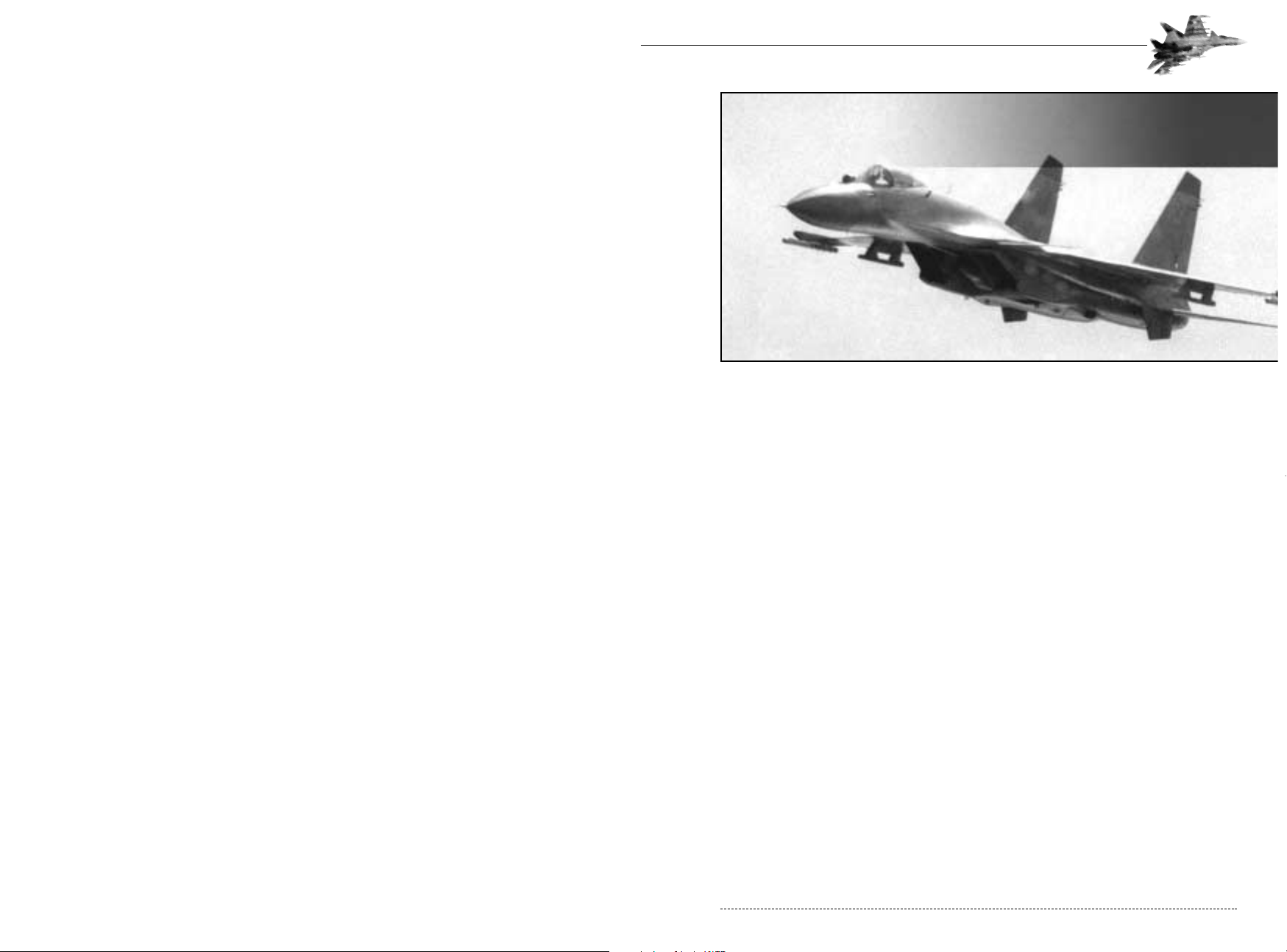
Defense Visual Information Center - Department of Defense

Su-33 – Originally designated the Su-27K, this variant is specifically designed for the demanding
role of carrier-based aviation. Equipped with canards for improved take off and landing performance, the first Su-27K made its maiden flight in 1985. The shortened tailcone, intended to
reduce risk of tail strike during high AOA landing, reduces the space for defensive equipment
(including chaff and flare dispensers). Whereas the Su-27 was tailored primarily as an air-to-air
interceptor, the Su-33 is a multi-role aircraft (a necessity of carrier based aviation operating far
from home bases). The Su-33 retains to a large extent the avionics and cockpit of the basic Su-27.
Su-34 – Also known as the Su-32FN, this aircraft is a two-seat (side by side cockpit), longrange, day/night fighter-bomber, intended to replace the MiG-27, Su-17, and Su-24. The Su-34
first flew on December 18, 1993. Canards improve manoeuvreability, and an elongated tailcone
reportedly houses aft facing missile guiding systems. The aircraft features an improved glass cockpit along with the traditional analog gauges. Besides having a unique ejection system and terrain
following radar, the aircraft actually has a toilet and sleeping facilities onboard.
Su-35 – Originally designated the Su-27M, this multi-role variant of the Su-27 features improved
avionics; a modern “glass cockpit” replacing the traditional analog gauges with multi-function displays and digital readouts. The collapse of the Soviet Union has hindered the deployment of the
Su-35, prototypes of which perform routinely at international airshows.
Su-37 – Having appeared at numerous airshows, this variant is basically an Su-35 equipped with
thrust vectoring engine exhausts for improved low-speed agility. Russia has stated that this will
eventually become the standard operating variant.
Ready For Action
This concludes our introduction to the Flanker family, arguably the most powerful and versatile
group of aircraft ever built. Chapter 2 will orient you with the simulation interface and explain how
to get airborne quickly.
CHAPTER 1: Flanker Briefing 3
The program, though, quickly began to experience problems. The second prototype, number T-102, suffered control system failure, and the pilot was killed during ejection. By 1979, additional prototypes were flying, but the program was failing to meet its performance requirements. Drag was
higher than expected, engine performance was low, fuel consumption was too high, and heavy
avionics in the nose decreased stability. Further, flutter problems required the addition of anti flutter weights in the tailfins, tailplanes, and wings. By this time, information about the F-15 indicated
the Flanker would be no match for the American jet in air-to-air combat. A redesign was needed.
Prototypes T-10-7 and T-10-8 were redesignated T-10S-1 and T-10S-2 and built to a substantially
improved design. An entirely new wing improved lift while offsetting the weight of the equipmentpacked nose. Anti-flutter weights, serving as wingtip missile launch rails, replaced the curved
wingtips of the early prototypes. The fuselage received substantial modifications, fins were
increased in size, and the airbrake was redesigned. The T-10S-1 first flew in 1981. Avionics problems continued to dog the program, though, and service deliveries didn’t begin until 1985, roughly
a decade after the F-15 entered service. One of the T-10S prototypes, redesignated as P-42, was
prepared to capture numerous aviation records from the F-15. Stripped of avionics and unnecessary gear, the P-42 was fitted with modified engines and set a total of 27 world records between
October 1986 and December 1988, including numerous time-to-height records.
Performance Characteristics
T-10-1 SU-27 SU-33 SU-34 SU-35
Powerplant
2 x AL-21F3 2 x AL-31F 2 x AL-35F 2 x AL35F 2 x AL-35F or AL-31MF
or AL-31MF or AL-31MF
Thrust Each Engine
11,220kg 12,522kg 14,029kg 14,029kg 14,029kg
Wingspan
14.8m 14.8m 14.8m 14.8m 15.1m
Height
5.92m 5.98m 5.95m 5.95m 6.42m
Max Takeoff Weight
25,786kg 30,000kg 30,000 kg. 44,400kg
Flanker Variants
Most legendary tactical aircraft share a common trait: versatility. The Flanker is no exception, with
numerous sub-variants arriving on the scene. Usually, aircraft variants are identified by adding a
letter to the base designation (F-16A, F-16B, F-16C, etc.), Sukhoi eventually abandoned this
method, giving each variant a new designation. Some speculate that this was intended to promote
the idea that each variant was a whole new aircraft, hopefully improving domestic funding as well
as overseas sales. Flanker operators include Belarus, Ukraine, Russia, India and China.
Su-30 – Initially called the Su-27PU, this is an improved version of the original Su-27UB two-seat
trainer. Unlike the Su-27UB, the Su-30 is a fully operational combat aircraft. It is optimized for missions lasting 10 or more hours, and would normally act as an airborne mission controller.
Su-30MK - This improved version of the Su-30 is optimized for delivery of precision-guided
munitions, some of which may have stand-off ranges of 120km (75 miles). The Su-30MK also features an improved navigation and weapons systems.
FLANKER 2.0
FLANKER 2.0
2 CHAPTER 1: Flanker Briefing
CHAPTER 2: Quick Start 5
QUICK START
The main menu provides several options for becoming airborne. The three quickest ways to takeoff
are via the Instant Combat, Training, and Mission menu modes.
Installation
You must install Flanker 2.0 game files to your hard drive and have the Flanker 2.0 CD in your CDROM drive to play this game.
To install the game, insert the CD into the CD-ROM drive. When the pop-up window appears,
click on the Install option. If you have disabled the Windows Autorun, or if it does not function,
Explore the CD and double-click on the Setup icon. Follow all on-screen prompts to complete the
installation.
What Comes with this Game?
Your game box should contain this user manual, a pilot checklist and a Flanker 2.0 CD. This user
manual explains how to play and contains important information on menus, scenarios, and unit
classes and equipment.
System Requirements
To play Flanker 2.0, be sure your system meets the following system requirements:
• Pentium 200 MHz IBM PC or compatible
• 32 MB of RAM
• Windows® 95 or 98 - NOTE: This is a Windows 95 game and cannot be played on Windows®
NT systems. Multitasking is not recommended when playing Flanker 2.0
• An uncompressed hard drive with at least 600MB free
• 8 X CD-ROM drive or faster
• A DirectX compliant 3D accelerated video card with 4MB of memory and a Colour SVGA
Monitor
• A 100% Microsoft (or Logitech) compatible mouse
• Microsoft mouse driver version 9.00 or higher or Logitech mouse driver version 6.24 or higher
• 100% DirectX Compatible Sound Card
CHAPTER 2
Quick Start
CHAPTER 2
Quick Start
FLANKER 2.0
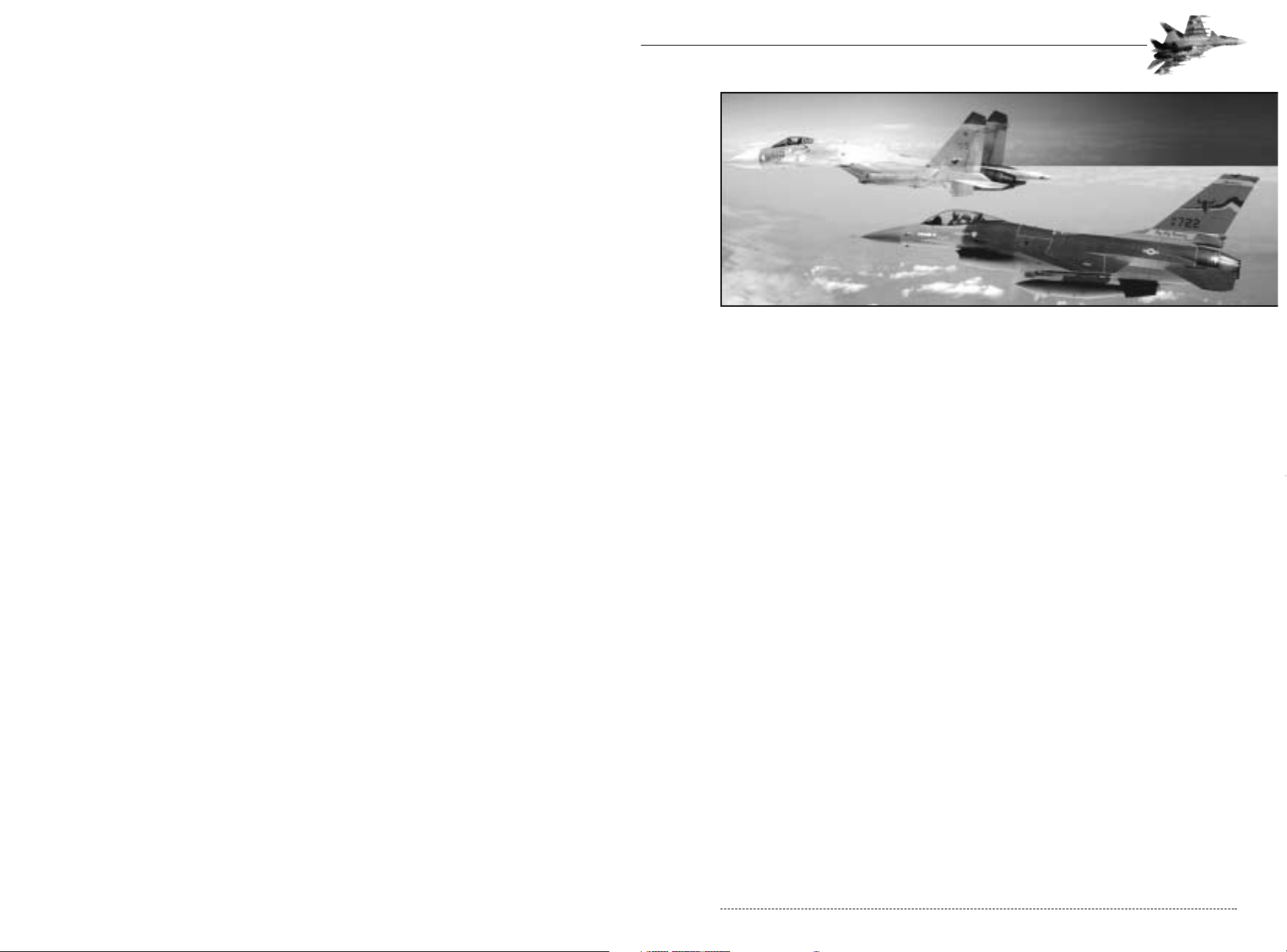
Defense Visual Information Center - Department of Defense
Despite the differences in operating environments, as a Flanker pilot you will find very little
difference between the two aircraft. The cockpits, controls, and avionics are virtually identical. The
Su-33 is a little heavier than the Su-27. The Su-33 has more powerful engines, but this performance advantage is somewhat offset by increased fuel capacity (for longer range) and increased
maximum takeoff weight. Except for the rigors of carrier takeoffs and landings, you should have
little difficulty switching between the two aircraft.
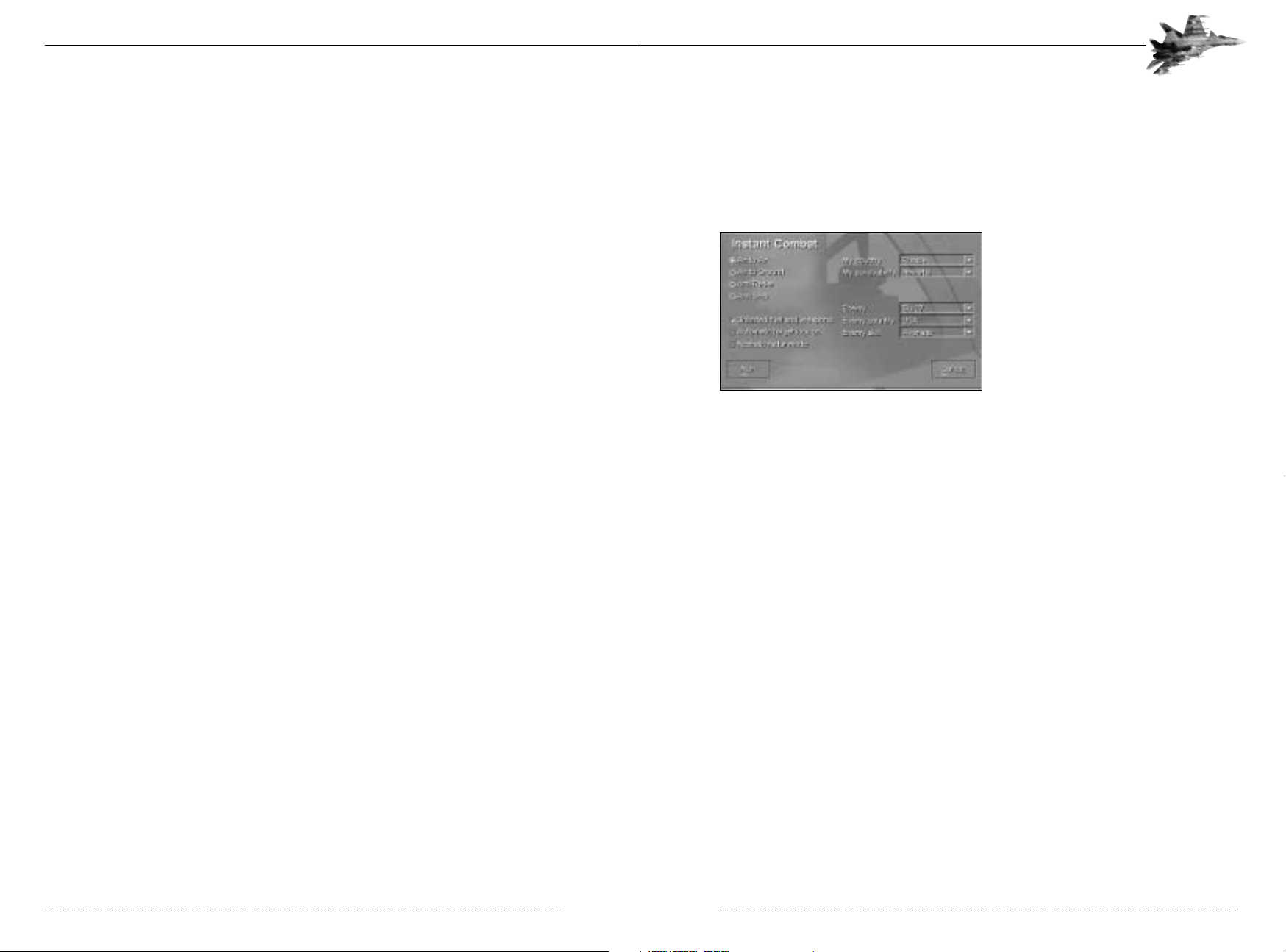
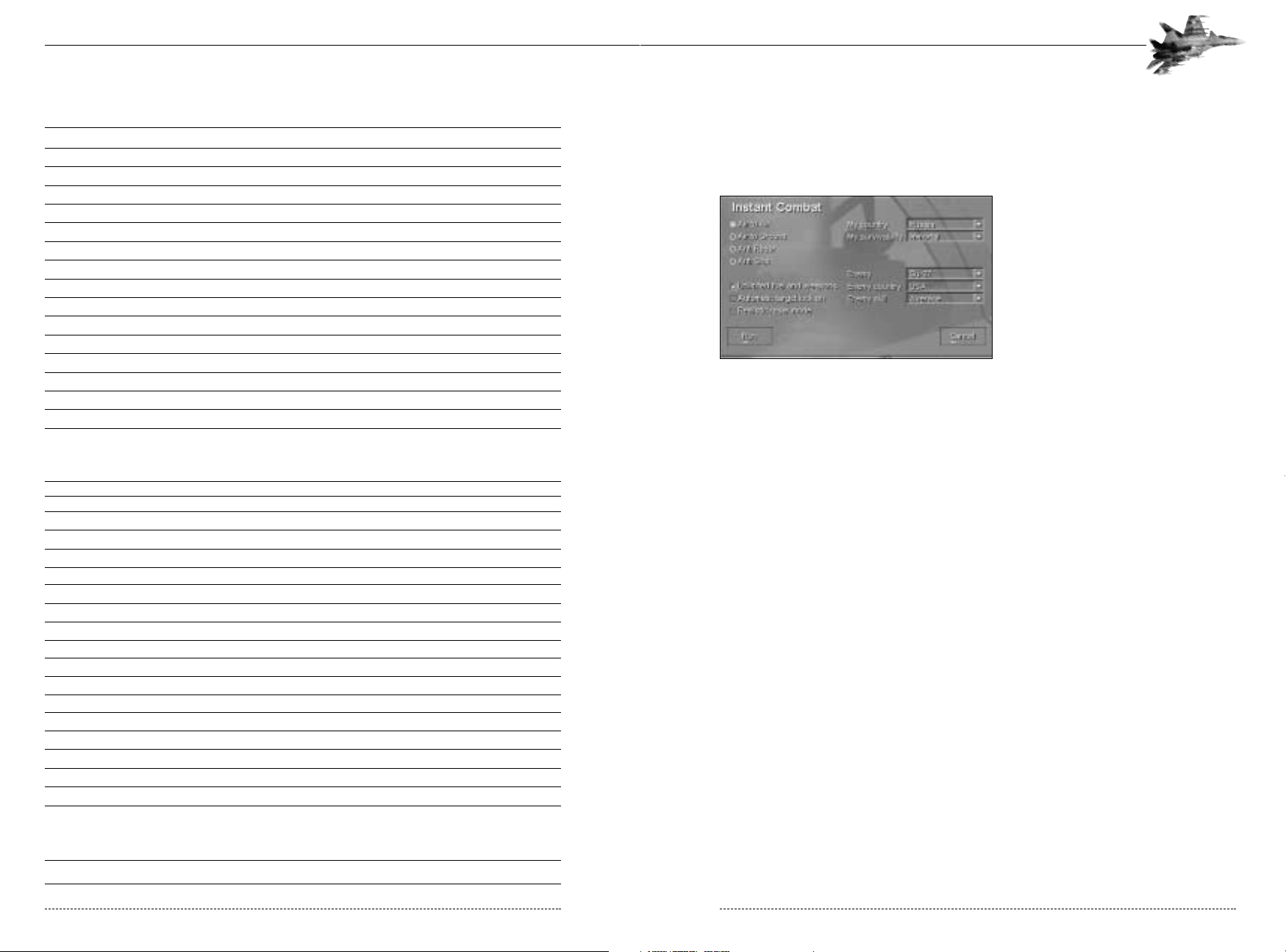
Instant Combat Mode
Instant Combat mode is the quickest way
to get airborne and take on an opponent.
It features a simplified radar and flight
model. From the main menu, select “Instant
Combat”, then select “Air-to-Air.” Check the
“unlimited fuel and weapons” and the
“automatic target lock-on” boxes. From the
pull-down menus, select “Russia” for my
country and “immortal” for my survivability.
For the enemy, select the type of aircraft you wish to fly against, select a country for it to fly for,
and specify the quality of the computer controlled pilot. When you’ve completed configuring the
scenario, select the “Run” button. You’ll be placed in a Flanker with an appropriate weapons load
out. The mission will generate a random number (1-6) of enemy targets. Manoeuvre toward your
target and engage!
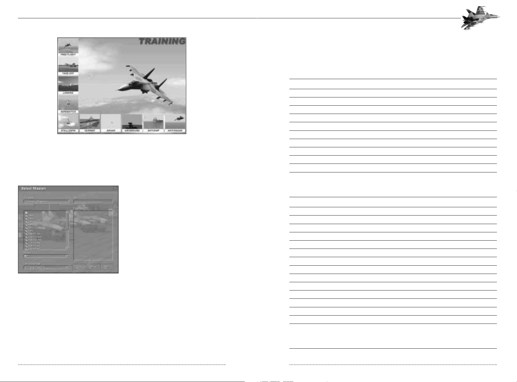
Training Mode
Training mode provides a series of pre-defined missions configured into ten categories. Each category may have several individual missions catering to specific training needs. Choose “Training”
from the main menu, the select the appropriate category (Free Flight, etc.) Next, select a specific
mission within that category group.
The pre-recorded training mission begins playing while the instructor pilot narrates. The instructor
will walk through the mission, explaining the procedure or task step-by-step. At anytime, you may
take control and complete the mission yourself by pressing the ESC key. We recommend allowing
the instructor to fully describe the task and complete the narration before taking manual control.
You may exit the mission by pressing the Ctrl-Q key.
CHAPTER 2: Overview 7
In addition to the basic system requirements, the game requires that DirectX 6.1 be installed to
your hard drive. The option to install DirectX 6.1 appears during the game installation. At the end
of installation, you are prompted to register Flanker 2.0 electronically. For network play, you need a
DirectPlay compatible network adapter.
Flanker 2.0 utilizes Microsoft DirectX sound and video drivers. DirectX is a programming tool created by Microsoft, and the installation of DirectX may cause video problems and system anomalies
with computers using video drivers that arenít DirectX compliant. DirectX is a Microsoft product,
and as such, this publisher cannot be responsible for changes that might occur to your computer
system due to its installation. For DirectX related problems that cannot be fixed by updating to
your video cardís latest Windows driver set, you must contact either Microsoft or the manufacturer
of your video card for further technical support or service.
Microsoft retains all intellectual property rights to DirectX. The user has been granted a limited
license to use DirectX with Microsoft operating system products.
Uninstalling the Game
To uninstall the game, select that option from the Autorun menu, or choose Settings from
the Windows 95 Start Button, and select Control Panel. In the Control Panel, select Add/Remove
Programs, left-click on Flanker 2.0,and click on the Add/Remove button. The game and all
of its components are then removed from your hard drive, except for your saved games or
edited scenarios.
OVERVIEW
We know you’re anxious to start flying, so this chapter is divided into two portions. The first portion describes how to get through the menus quickly, how to get airborne, and how to control the
aircraft. The second portion of this chapter explains each menu choice in more detail.
Su-27 vs Su-33
Flanker 2.0 lets you pilot either the Su-27 or Su-33. Your first question is probably, “What’s the difference?” The Su-33 is a navalized version of the basic Flanker; an aircraft designed to operate
from aircraft carriers. Whereas the Su-27 is a pure interceptor with no real secondary groundattack role, the nature of carrier-based aviation requires the Su-33 perform both ground-attack
and air-to-air duties. There may not a friendly airbase from which supporting Su-25’s can launch
and recover. The carrier’s Su-33s will have to perform both roles.
FLANKER 2.0
FLANKER 2.0
6 CHAPTER 2: Overview
2-1: The Four Forces of Flight
Key Commands
Now that you’re in the cockpit you need to know the basic controls. The following table shows the
key commands necessary to control the simulation.
PROGRAM CONTROL
KEY ACTION
Ctrl-A
Accelerate program speed by 2 times.
Ctrl-Q
Quit program from Main Menu, also ends mission
Alt-X
Quit Mission Editor and return to Main Menu
Ctrl-S
Toggle Sound On or Off
Ctrl-T
Cancel Trim Settings
Shift-M
Reset Audible Warnings
S
Toggle Pause/Resume normal speed
Esc
Allows user to take control of aircraft while viewing a track file playback
0
(zero) [not Key Pad 0] Turns on microphone for recording mission playback
Ctrl-L
Starts network play game from Mission Editor
Ctrl-M
Chat feature for multi-player network games
FLIGHT CONTROL
KEY ACTION
Down Arrow
Nose up (without joystick)
Up Arrow
Nose down (without joystick)
Left Arrow
Bank left (without joystick)
Right Arrow
Bank right (without joystick)
Ctrl-.
(Period) Trim up
Ctrl-;
(Semi-colon) Trim down
Ctrl-,
(Comma) Trim left
Ctrl-/
(Slash) Trim right
Z
Rudder left (in flight), left turn (taxi)
X
Rudder right (in flight), right turn (taxi)
Ctrl-Z
Trim left rudder
Ctrl-X
Trim right rudder
H
Toggle altitude stabilization mode
J
Toggle auto-throttle
K
Execute “Pugachev’s Cobra”
CHAPTER 2: Overview 9
2-3: The Training Mission Screen
Missions Mode
From this menu you can review and load all
saved missions available in the game, including pre-defined missions that come with the
simulator as well as those you’ve added.
You can use the mission mode to begin a
campaign or simply fly an individual sortie.
Simply click on the desired mission and
click the Run button.
2-2: The Mission Mode Select Screen
FLANKER 2.0
FLANKER 2.0
8 CHAPTER 2: Overview

KEY ACTION
6
Select Longitudinal Missile Aiming (LNGT/FIO) mode
7
Select Air-to-ground (GND/ZEMLYA) mode
`
Cycle through targets on MFD in AWACS and Ground Attack Modes
Tab
Place designated contact in Track While Scan from Scan
Ctrl-Tab
Remove tracked contact from Track While Scan
Tab
Lock tracked target to Attack Mode
Tab
Lock/unlock target to Attack Mode in CAC submodes
Ctrl-H
Cycle through Heads Up Display (HUD) intensities
WEAPONS
KEY ACTION
D
Cycle through weapons selection
C
Toggle cannon
Q
Dispense chaff & flare
Shift-Q
Continuously dispense chaff & flares (Note: until supply is exhausted)
Spacebar
Fire current weapon
Ctrl+W
Jettison weapons in pairs while airborne, reloads weapons while on the ground
RADAR & ELECTRO-OPTICAL SYSTEMS
KEY ACTION
I
Toggle radar illumination on or off
O
Toggle Electo-Optical System (EOS) or weapon TV seeker on or off
Ctrl-I
Center radar antenna/Infra-Red Scan and Track(ISRT) ball
-
(Minus) Multi-Functional Display (MFD) zoom in
+
(Plus) Multi-Functional Display zoom out
Ctrl-V
Toggle Salvo mode on or off
BEYOND VISUAL RANGE MODE
KEY ACTION
Shift-;
(Semicolon) Move radar/EOS scan zone DOWN while in BVR
Shift-,
(Comma) Move radar/EOS scan zone LEFT while in BVR
Shift-.
(Period) Move radar/EOS scan zone UP while in BVR
Shift-/
(Slash) Move radar/EOS scan zone RIGHT while in BVR
;
(Semicolon) Move HUD target designator Box DOWN (BVR only)
,
(Comma) Move HUD target designator Box LEFT (BVR only)
.
(Period) Move HUD target designator Box UP (BVR only)
/
(Slash) Move HUD target designator Box RIGHT (BVR only)
CHAPTER 2: Overview 11
THROTTLE CONTROL
KEY ACTION
Page Up
Increase Throttle in increments (without throttle option enabled )
Page Down
Decrease Throttle in increments (without throttle option enabled )
Key Pad +
(Plus) Increase Throttle smoothly (without throttle option enabled )
Key Pad -
(Minus) Decrease Throttle smoothly (without throttle option enabled )
MECHANICAL SYSTEMS CONTROL
KEY ACTION
B
Toggle airbrake
Shift-B
Airbrake out
Ctrl-B
Airbrake in
Ctrl-E,E,E
Eject (Note: hold down Ctrl key and hit E three times)
E
Toggle active jamming (requires ECM pods in loadout)
F
Toggle flaps up/down
Shift-F
Flaps down
Ctrl-F
Flaps up
G
Toggle landing gear up/down
Ctrl-G
Toggle arrestor hook down or up (Note: Su-33 only, not Su-27)
P
Release drogue chute (Note: Su-27 only, not Su-33)
Ctrl-P
Toggle folding wings (Note: Su-33 only, not Su-27)
L
Dump fuel (in flight) or refuel (ground) (Note: Hold down key)
W
Engage wheel brakes (ground) (Note: Hold down key)
T
Toggle wingtip smoke
Shift-M
Reset Current Audible Warning
NAVIGATION
KEY ACTION
`
Select next waypoint or airfield
A
Toggle autopilot
1
Toggle to set Navigation (NAV) submodes
COMBAT MODES
2
Toggle to set Beyond Visual Range (BVR/DVB) submodes
3
Select Close Air Combat – Vertical Scan (CAC/BVB – VS) submode
4
Select Close Air Combat – Bore (CAC/BVB – BORE/STR) submode
5 Select Close Air Combat – Helmet-Mounted Target Designator
(CAC/BVB – HMTD/SHLEM) mode
FLANKER 2.0
FLANKER 2.0
10 CHAPTER 2: Overview

KEY ACTION
Shift-F8
Target View – Your Aircraft to Target
F9
Ship View
Alt-F9
Landing Signal Officer (LSO) View
F10
Theater View
F11
Tower & Terrain View
Ctrl-Key Pad 5
Returns to Tower & Terrain View starting point or ends Padlock View
F12
Static Objects View
VIEW MODIFIERS
KEY ACTION
Ctrl-Home
Places external views to Friendly only
Ctrl-End
Places external views to Enemy only
Ctrl-Delete
Places external views to All
Ctrl-Insert
Places external views to Unknown (non-aligned) only
Key Pad Delete
Toggle Padlock View (Note: for Alt-F9 LSO View & F11 Tower View only)
Ctrl-Key Pad + (plus)
Switch to Weapons Release and Track View for F2 External, F4 Chase, F7 Active Ground Targets,
and F9 Ship Views only
Y
External View Information Display Toggle
COCKPIT VIEW CONTROL
KEY ACTION
Key Pad 1
Move head down and left
Key Pad 2
Move head down
Key Pad 3
Move head down and right
Key Pad 4
Move head left
Key Pad 5
Front View
Key Pad 6
Move head right
Key Pad 7
Move head up and left
Key Pad 8
Move head up
Key Pad 9
Move head up and right
Key Pad *
(Asterisk) Toggle Padlock View (Note: Must be in Cockpit View and in visual range)
M
Move head to view right mirror
N
Move head to view left mirror
CHAPTER 2: Overview 13
CLOSE AIR COMBAT MODE
KEY ACTION
;
(Semicolon) Move radar/EOS scan zone DOWN while in BVR
,
(Comma) Move radar/EOS scan zone LEFT while in BVR
.
(Period) Move radar/EOS scan zone UP while in BVR
/
(Slash) Move radar/EOS scan zone RIGHT while in BVR
GROUND MODE
KEY ACTION
;
(Semicolon) Move radar/TV seeker scan zone UP
,
(Comma) Move radar/ TV seeker scan zone LEFT
.
(Period) Move radar/ TV seeker scan zone DOWN
/
(Slash) Move radar/ TV seeker scan zone RIGHT
WINGMAN COMMANDS
KEY ACTION
End
Dispatch wingman on mission & allow him to return to base afterwards
Del
Dispatch wingman on mission. On mission completion, join up
Home
Join up in formation
Ins
Toggle tight formation or loose formation
[
Attack my target
]
Cover my six o’clock (rear) position
VIEW SELECTION
KEY ACTION
F1
Cockpit View
Ctrl-F1
Natural Head Movement View
Key Pad *
(Asterisk) Padlock View (Note: Must be in Cockpit View and in visual range)
F2
External View – All Aircraft
F3
Fly-By View
F4
Chase View
F5
Air Combat View
F6
Weapons View
F7
Active Ground Objects View
F8
Target View
Ctrl-F8
Target View – Target to Your Aircraft
FLANKER 2.0
FLANKER 2.0
12 CHAPTER 2: Overview
THE MAIN MENU
The main Flanker 2.0 menu provides access to five modes of play, an options screen and a
reference encyclopedia. This section describes each of these items.
Instant Combat
The Instant Combat mode provides a
quick way to fly an Su-27 or Su-33
against hostile forces. First select the
type of mission, air-to-air, air-to-ground,
anti-radar or anti-ship. As the names
imply, the mission types determine the
types of targets available during the
mission. Select anti-radar, for example,
to practice targeting various radar systems. Select anti-ship to practice
attacking different ships.
2-4: The Instant Combat Mode Setup Screen
Next, configure your aircraft. The “My Country” pull down menu specifies which country you’re
flying for. “My Survivability” indicates how resistant your aircraft is to damage. Configure who and
what you want to fly against in the mission and then select Run.
To exit a mission, simply select the Ctrl+Q key.
My country
You may choose to fly a Su-27 for Russia, the Ukraine, Turkey, the USA or Unknown.
My survivability
• Immortal: You cannot be killed. Your aircraft takes not damage and your aircraft will “bounce”
off the ground.
• Good: Your aircraft can be killed 3 times and then it will take damage normally.
• Realistic: Your aircraft will take damage normally.
Enemy
Depending upon the type of mission you select, this box will allow you to fight against all of the
types of opponents available in the game.
Enemy country
You can choose to fight against Russia, the Ukraine, Turkey, the USA or Unknown. This choice
does not limit what types of opponents you can select.
Enemy skill
You can select Average, Good, High, Excellent and Random.
Instant Combat Options
• Unlimited fuel and Weapons: This option gives you an unlimited amount of ordnance and fuel
to fight with.
CHAPTER 2: The Main Menu 15
EXTERNAL VIEW CONTROL
KEY ACTION
Key Pad 1 Move viewpoint down and left
Key Pad 2
Move viewpoint down
Key Pad 3
Move viewpoint down and right
Key Pad 4
Move viewpoint left
Key Pad 5
Centers view (Stops moving camera in F11 Tower & Terrain View)
Ctrl-Key Pad 5
Returns to starting point (F11Tower & Terrain View only)
Key Pad 6
Move viewpoint right
Key Pad 7
Move head up and left
Key Pad 8
Move viewpoint up
Key Pad 9
Move head up and right
Key Pad *
(Asterisk) Zoom in
Key Pad / (Slash) Zoom out
Key Pad 0
Jump to head-down cockpit view and back (Note: Hold down then release)
Alt-Key Pad *
(Asterisk) Starts moving camera forward (F11Tower & Terrain View only)
Alt-Key Pad / (Slash) Starts moving camera backward (F11Tower & Terrain View only)
Shift-(all view keys)
Moves viewpoints at a faster rate (Note: Hold down Shift and key)
MISSION EDITOR -
Hold down Ctrl to select multiple objects
KEY ACTION
FILE
Ctrl-N
Create new mission file
Ctrl-O
Open mission file
Ctrl-A
Save mission file
Alt-X
Exit Mission Editor and return to Main Menu
EDIT
Ctrl-Z
Undo last action
Ctrl-Y
Redo last action (cancel previous Undo)
Del
Delete selected object
VIEW
Ctrl-H
Hide objects
Ctrl-1
Crimean view
FLIGHT
Ctrl-B
Display Briefing
Ctrl-F
Start Mission
Ctrl-L
Network Play
Ctrl-M
Chat in Network Play
Ctrl-R
Record Track File
CAMPAIGN
KEY ACTION
Alt-Z
Remove objects from Condition
FLANKER 2.0
FLANKER 2.0
14 CHAPTER 2: Overview
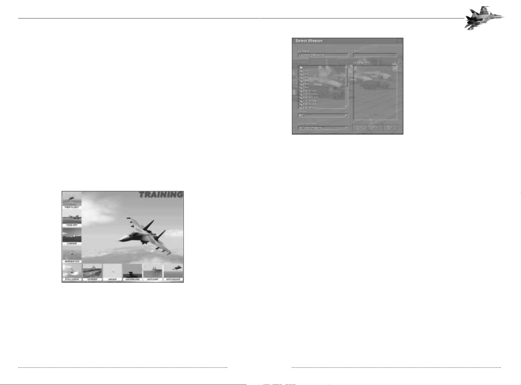
After you select the mission button on
the main screen, you will see the
Mission selection screen. The missions
are divided into directories, by mission
type. When you select a mission, the
mission briefing will appear in the
Description area on the right side of the
menu. As you will notice, you can
search for saved and previously built
missions from almost any location by
using the drive (if you have multiple drives or you are connected to a network).
Once you have selected a mission,
press the Run to button to go straight
into the mission. Select the View key to
view the mission within the Editor.
File Naming Convention
All of the playable files in Flanker have a naming convention which will automatically be created
when you save that file. You can search for files by type, by using the “List files of type” box on
the Select Mission menu. They file types are:
• Flanker Missions: *.mis
• Demo missions (tracks): *.trk
• Saved Missions: *.sav
• Debriefings: *.stt
Some basics about viewing your mission in the Editor:
• Your flight is shown in white. If you select it, you will see an Airgroup planning menu appear,
with all of the information about your flight. This information includes:
• Aircraft mission
• Payload
• Fuel
• Route with waypoint altitudes, speeds, tasks, estimated times and targets.
• Other flights and vehicles are shown in the colour of their nation. Selecting them will bring up a
menu showing their information.
• Selecting Met report from the Options (Alt+O) pull down menu in the Editor will allow you to
view the mission’s weather conditions.
• Selecting Skills from the Options (Alt+O) pull down menu in the Editor will allow you to view the
mission’s Skills settings
• Selecting the Edit (Alt+E) pull down menu in the Editor will allow you to see if the mission is
Classified. If the Classify selection is unavailable, then the mission is classified. This means that
you can look at the information in the mission, but you cannot change it.
• If you select to play a saved mission (*.sav) or a track (*.trk), you will also not be able to change
anything when you view it in the Editor.
CHAPTER 2: The Main Menu 17
• Automatic target lock on: This option means that when the mission starts with your radar locked
onto an enemy target.
• Realistic radar mode: In Instant Combat, the radar is defaulted to a simplified mode. You simply
manoeuvre your aircraft in the direction of the enemy and select the TAB key (assuming you do
not have the automatic target lock on option selected) to lock onto the target. To select another
target, use the (~) key to cycle through the targets.
If you select the Realistic radar mode, then you can select and use the real radar. The radar starts
off the mission in the simplified mode and then you can change to realistic ones as you play. For
more information on realistic radar, see Chapter 4. If you do not select this option, then your radar
will be locked into the simplified mode for the entire mission.
Next, configure your enemy aircraft. Select the type of aircraft you wish to fly against, which
country it flies for, and the quality of the computer controlled pilot.
Training
The training mode contains a series of customized, talking training missions focusing on specific
pilot procedures. The missions have been pre-recorded so you may either watch the procedure
performed by an experienced instructor pilot, or practice it yourself. The instructor will speak while
the mission plays, describing the situation and what you should be doing. The instructor will prompt
you to take control of the aircraft at your convenience by pressing the Esc Key or you can restart
the mission and take control at the beginning. To exit the mission, select the Control+Q key.
2-3: The Training Mission Screen>>
The individual training missions are described in Chapter 7.
Missions
Mission Mode provides direct access to all missions installed on your computer, including those
that ship with the game as well as ones you create or install later. This mode lets you view all missions, read their descriptions, and launch them without opening the mission editor.
FLANKER 2.0
FLANKER 2.0
16 CHAPTER 2: The Main Menu
Options
Flanker 2.0 is designed for a wide range of computers. You
need to be away of the specifications of your computer and
what options will effect the performance while you play the
game. If you are playing an air to air mission, you might be
less concerned with the ground textures or the greenery
density, so you would turn these down to increase the
game’s performance.
Also, it is very important that you optimize your computer to get
the best performance. See the troubleshooting and recommended options sections at the end of this chapter and the
readme for more information on this.
2-8: The Options Screen
Graphics
The graphics section of the Options menu allows you to set your screen resolution and the major
items that effect your overall game graphics.
• Resoultion: Flanker 2.0 supports three resolutions: 640x480, 800x600, and 1024x768. Higher
resolutions look better, but require more CPU horsepower. Lower resolutions may not appear as
sharp, but will provide smoother frame rates on slower machines. Checking the “full screen” box
ensures the program runs in full screen mode instead of in a window and may help your game’s
performance.
• Texture Noise: An effect that adds raised, 3D textures to a texture map. An example might be
rivet on the side of an aircraft. This adds realism, but decreases performance.
• No Textures: This will turn off all of the 3D textures in the game. If the option is selected, ground,
objects, map, etc. are solid. You may also disable the editor textures (found in the Miscellaneous
section of the Options menu) when this is selected. This will option will greatly speed your
game’s performance, but also reduce all visual effects.
• Mipmapping: Specifies the use of textures. If the option is selected, several textures are used for
image of one object at various distances. If the option is unselected, only one texture is used. In
this case the distortions are greater. This option decreases performance.
• Primary display adapter: This allows you to choose to play the game using your primary or (if you
have on) a secondary card. Most people will have this box checked.
• 32 bit: This allows you to play the game in 32 bit colour. Be sure that your video card supports a
32 bit colour setting,
CHAPTER 2: The Main Menu 19
• Not all items in the mission may be viewed. In some cases the person who made the mission
may have Hidden units to add an element of surprise.
• Once you are done looking at your mission, select the Start mission button (Ctrl+F) or to record
the mission as a track (Ctrl+R).
• For more detailed information, see Chapter 10 on the Editor.
Campaign
Flanker 2.0 comes with a campaign consisting of a series of branching, inter-linked phases. By
using the campaign tools in the mission editor to create new campaigns, the number of possible
campaigns are limitless.
When you select the Campaign button on the Main Menu, the Select mission menu will be opened
to the campaign directory. Campaigns have the same file names as regular missions (*.mis).
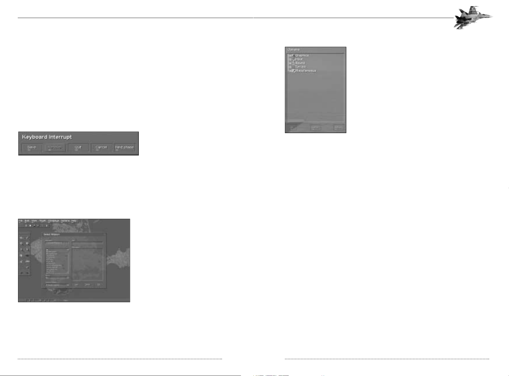
2-12: Next Phase Button
Campaigns initially play just like missions. At the end of the first phase in a campaign (select the
Ctrl+Q key to end the phase), you will get an option to go onto the next phase. When you select
that button, you will be taken to following phase of the campaign, if there is one and if you met the
conditions to do so.
Editor
Flanker 2.0 includes a powerful mission
editor, letting you create an infinite number of scenarios and campaigns that
can then be traded with your fellow
Flanker 2.0 pilots. Missions may be
“classified” or locked to prevent others
from editing them and viewing their
contents before flying. By ensuring that
the “surprise factor” is maintained, classified missions provide a stable base for
player-run competitions.
2-7: The Mission Editor
The mission editor is fully explained in Chapter 11.
FLANKER 2.0
FLANKER 2.0
18 CHAPTER 2: The Main Menu
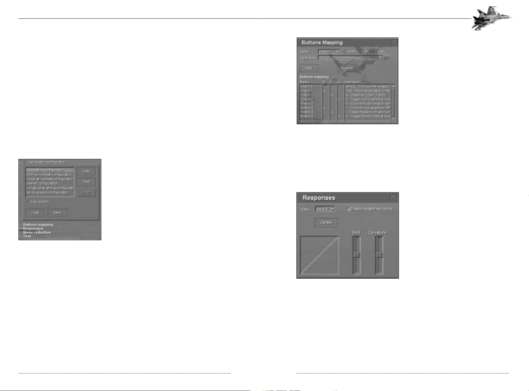
The Button Mapping menu shows all of the
buttons on your controller and the functions
that they have been assigned. The S, C, and
A columns signify if a Shift, Control, or Alt button needs to be depressed when this button
is pushed to perform this action. To remove
an action, highlight the desired button in the
window and then press the Remove button.
To add a button action, select the button you
want to add in the Button box at the top of
the menu, select whether you want to have
the Shift, Ctrl or Alt key depressed and then
select the action in the Command box. After
you have the action set the way you want it,
press the Add button. Once you have the
setup for that configuration the way you want
it, then close the Button Mapping menu and move onto the next configuration mode that you wish
to change. After you are done, press the Save button and save your new setup.
If you want to clear all actions from a configuration mode and start fresh, select the highlight the
configuration mode and then press the Clear key. This will wipe out all of your button actions for
that configuration mode. If you want to copy a configuration mode, select the configuration mode,
press the Copy key, select the new configuration mode and then press the Paste Key.
Selecting Responses brings up the
Responses menu and allows you to change
the shift and curvature on the X, Y, Z and R
axis for your controller in each of the configuration modes. Select the Enable Response
Curve box and then adjust the shift and curvature as desired. If you want to re-center it,
select the Center key. This means that if you
want a more responsive controller when your
aircraft is in the Close Air Combat mode than
in the Navigation mode, you can make that
change here.
2-15: Responses Menu
CHAPTER 2: The Main Menu 21
Input
The input menu lets you select what devices you have connected to your computer: joystick,
thrust controller, secondary thrust controller (for dual throttle control), and/or rudder pedals.
Joystick: Select this option if you are using a joystick. If you do select this option, then the keyboard commands for your basic flight options (right, left, up, down arrows, etc.) will not function.
Always insure that your joystick is calibrated and tested in Windows before you start Flanker 2.0.
Use joystick configuration:
This feature allows you to customize the configuration of your joystick within Flanker 2.0. This is a
very powerful feature which not only allows you to select what your controller does, but also what
it does when a certain combat mode is being used in a mission. Example: You may want button
1 on your joystick to select your next waypoint while your aircraft is flying in the navigation mode.
But when you select the Close Air Combat mode, you want that button to cycle through the onboard weapons. This can all be done using the joystick configuration.
To have the setup switch between configurations within the game, ensure that the Auto Switch
box is checked.
To load a pre-made setup, select the Load button on
Joystick Configuration menu. You will then get a
menu that lists a number of specific and generic controllers. Select the one that best fits your controller
and select the Load button. Your controller will now
use that setup. To view what action each button does
in each configuration mode, select the configuration
mode on the Joystick Configuration menu (Example:
Navigation, BVR, etc.) and then select Button
Mapping. This will bring up the Button Mapping
menu. All of the configurations modes (Navigation,
BVR, Close Air Combat, etc.) for the pre-made set-ups
are the same. Customize them to fit your likes.
2-13: Joystick Configuration
To have the setup switch between configurations within the game, ensure that the Auto Switch
box is checked.
FLANKER 2.0
FLANKER 2.0
20 CHAPTER 2: The Main Menu
Caption 2-14: Button Mapping Menu
• Volume: Overall volume.
• Voice: Voices (Nagging Nadia, Instructor, Wingmen, etc.).
• Sound: Sound effects.
• Music: Music (Which only occurs while a mission is not progress).
• Recording: Your recordings within the game.
• Polyphony: Multiple sounds occurring at once.
Below the Sounds Level menu, there is a box to select your sound card driver.
Terrain
The terrain options menu lets you configure the visual quality and detail of the terrain and ground
objects, allowing you to customize performance for your computer and video card. You can adjust
detail levels for Textures, Objects, Greenery, and Roads/Rivers along with setting visibility ranges.
Higher/Farther settings will improve the graphics presentation, but reduce frame rate.
Lower/Nearer settings will decrease graphics quality, but will improve frame rate.
Misc
The miscellaneous options control how the program appears during play. Most of these options
configure the graphics and directly impact frame rate during game play. Users with slower
machines near the lower end of the recommended specifications may need to disable some of
these features to improve frame rate.
• HUD in Russian: If this is not selected, the HUD will be in English.
• G-Effects: When selected, you will see blackout and redout effects.
• Cockpit Mirrors: Enables/disables the mirrors position on the canopy rails.
• Cockpit Reflection: Enables a reflection on your canopy.
• Shadows: Enables aircraft shadows.
• Non-transparent Dialog Boxes: Toggles on opaque menus and dialogue boxes.
• Disable Editor Textures: Can only be selected if the “No Textures” option has been selected.
Turns off all textures in the Editor.
• Disable Buttons Animation: Enables/Disables all button animations in the game.
CHAPTER 2: The Main Menu 23
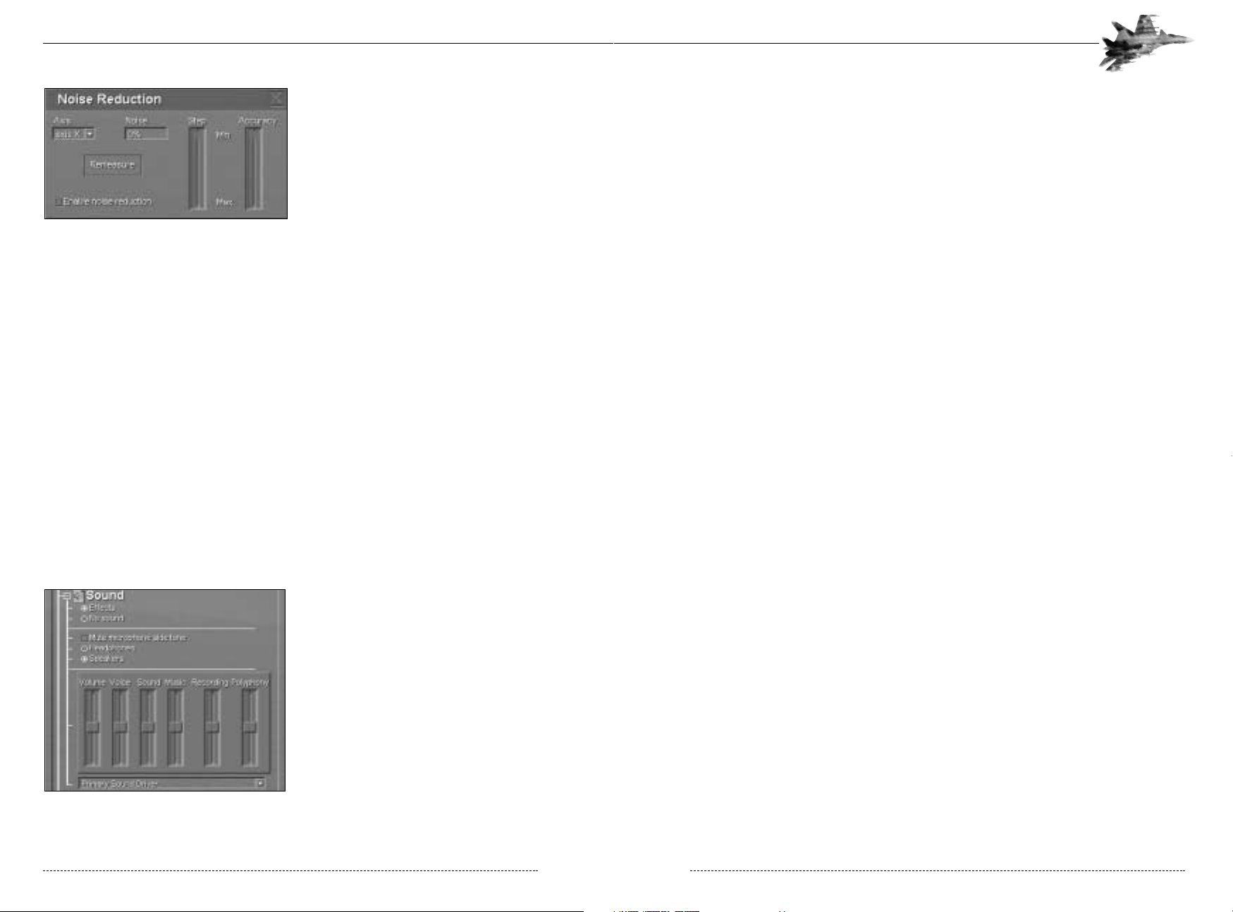
Selecting Noise Reduction brings up the
Noise Reduction menu and allows you to
change the Step and Accuracy on the X, Y,
Z and R axis for your controller in each of
the configuration modes. Select the Enable
Noise Reduction box and then adjust the
Step and Accuracy as desired. Move the
controller to measure the noise. If you want
to re-measure it, select the Re-measure key.
2-16: Noise Reduction Menu
Selecting Test allows you to see the range of motion on your controller, thrust and rudder pedals.
It also enables you to view the actions that buttons are set to when pressed.
Checking the Thrust, Second Thrust and Rudder Pedals allows you to use these controllers in
the game.
Sound
There are a variety of sounds in Flanker 2.0 that add to the overall experience and allow you to
immerse yourself more in the game. There are some important warnings and ambient sounds that
occur within the game (like an incoming missile warning). You will be at a serious disadvantage if
you are not able to hear them. You may also record your voice during missions (if you are using a
microphone). All of these options are set here.
• Effects/No Sounds: This turns all sounds on/off in the game.
• Mute microphone: The game will not record any sound coming from your microphone if this
is selected.
• Headphones/Speakers: Select the option you are using for better sound.
The Sound Levels menu found in the Options
menu, allows you to adjust the various audio
effects within the game.
2-17: Sound Levels Menu
FLANKER 2.0
FLANKER 2.0
22 CHAPTER 2: The Main Menu
• Have no other programs running while playing the game. You may want to even disable some
applications that begin at startup. See the readme for more details.
• Ensure that you have at least 250MB of free hard drive space on your primary hard drive for
swap file space.
• Select the Options settings in the game that best fit your computer.
• In playing a 3D game, realize that the bigger the mission and the more objects that are in that
mission, the slower your performance will be. If you find that your performance is still slow after
optimizing your computer, then try running smaller missions.
Recommended Options Settings
Below are some recommended settings for various computer specifications. These selections
seem to be a good balance between game play and performance. Your mileage may vary.
CPU
200 MHZ PENTIUM 300 MHZ PENTIUM II 400MHZ PENTIUM II 500 MHZ PENTIUM III
RAM Memory
32 MB 64 MB 128 MB 256 MB
3D accelerated video card
4MB RAM 16MB RAM PCI 32MB AGP 32MB AGP
(Voodoo2 and above)
Resolution (Full Screen)
640x480 800x600 800x600 1024x768
Texture Noise
Off Off On On
No Texture
On Off Off Off
Mipmapping
Off Off On On
Texture Resolution
Low Medium High High
Objects Density
Empty Low Medium High
Greenery Density
Low Medium Medium High
Roads, Rivers
Empty Low High High
Details Visibility
Near Medium Far Far
Chimney Smoke
Off Off On On
G-Effects
Off On On On
Cockpit Mirrors
Off Off On On
Cockpit Reflection
Off On Off On
Shadows
Off Off On On
Non-transparent
On Off Off Off
dialog boxes
Disable Editor Textures
On Off Off Off
Disable Buttons Animation
On Off Off Off
CHAPTER 2: The Main Menu 25
Network Play
Network play allows you and your friends to fly together either via local area network or over the
internet, and supports both IPX and TCP/IP protocols. Details on hosting and connecting to
multiplayer hosts are provided in Chapter 11.
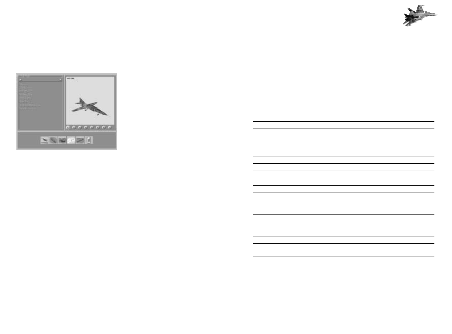
Encyclopedia
The encyclopedia provides an online
reference for all air, land, and sea vehicles used in the simulation. Begin by
clicking on the category button to
select the object category you’re interested in, then cycle through the available entries by selecting the drop
down menu below it. The controls in
the upper lright part of the menu allow
you to change your view of the model.
2-9: The Encyclopedia
Troubleshooting
Flanker 2.0 is a very complex game with a lot of features that can enhance your gameplay, but
also drag on your performance (frame rate, graphics, etc.). In order to ensure that you have the
most enjoyment possible, please take into consideration the following:
Game Play
• While there are almost always bugs in a game (even though we hate to admit it), the majority of
problems that players see are not actually problems, but simply that the player did not understand how the game works. Please read the manual and the readme thoroughly.
• Patches, new missions, campaigns and information can be found at the Flanker 2.0 website:
www.flanker2.com
Computer Setup
• Ensure that you have the latest drivers for all of your hardware. The number one cause of graphics problems is old video card drivers.
• Defrag your hard drive. This should be done prior to installation of Flanker 2.0. Sometimes
Windows will say that you have a low fragmentation percentage and that you do not need to run
the defragmentation program. Defrag your hard drive anyways and your should get better performance.
• Run Scan Disk before you install also. This will help insure a clean installation.
FLANKER 2.0
FLANKER 2.0
24 CHAPTER 2: The Main Menu
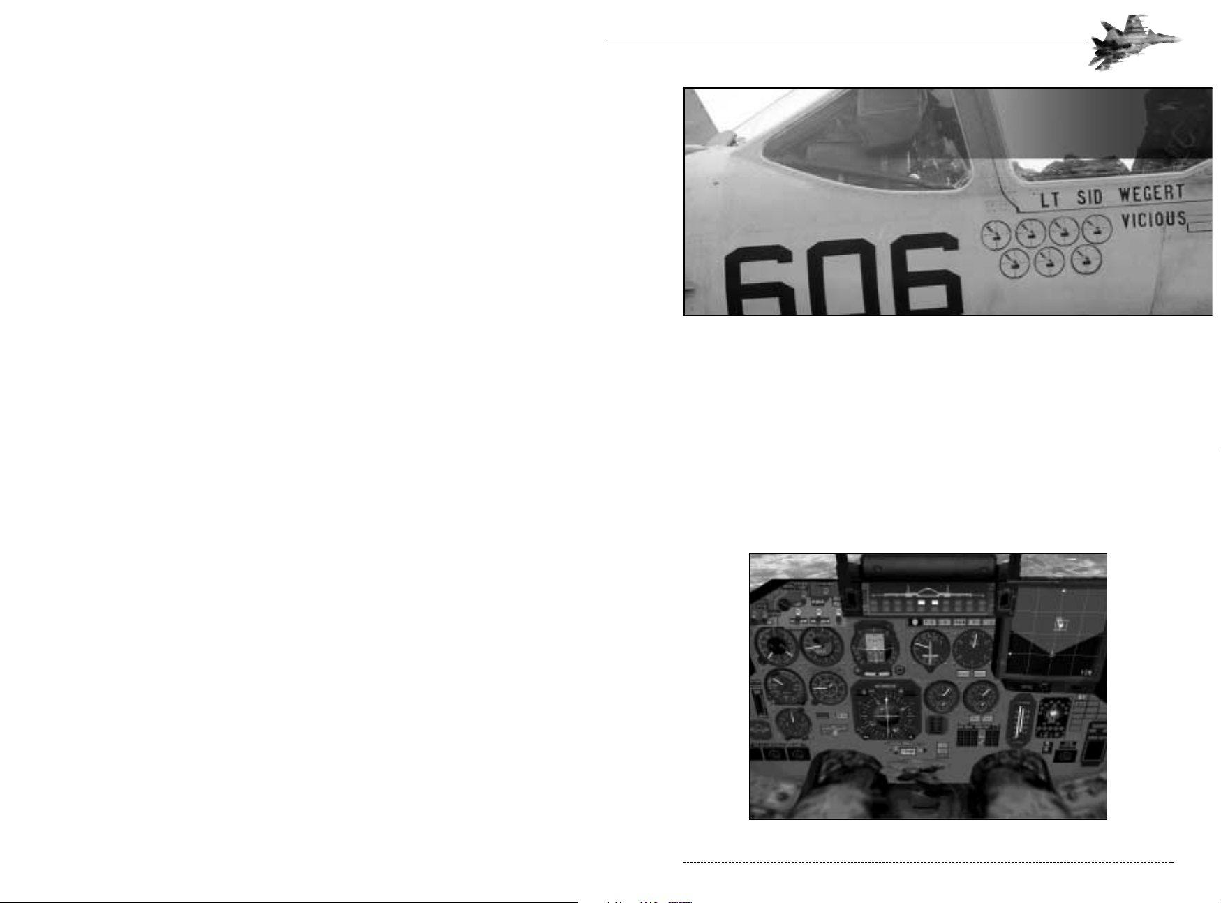
CHAPTER 3: Instrument Panel 27
The cockpit of the Su-27 can be divided into two main sections: the Instrument Panel and the
Head Up Display (HUD). The panel contains most of the flight instruments. The HUD displays the
main navigational and combat information; its detailed description is given below in a separate
section. A number of indicators, buttons and levers, including the Throttle, are located on the side
panels of the cockpit, but this manual does not describe them because of their unimportance to
this package.
INSTRUMENT PANEL
Use the Numeric Keypad to move your head around. A front view of the Instrument Panel (pilot’s
head is lowered down) is shown in the figure below. The layout of the instruments, controls and
their operation almost completely correspond to those of the real Flanker.
The Instrument Panel
CHAPTER 3
Cockpit
CHAPTER 3
Cockpit
Defense Visual Information Center - Department of Defense
Radar Altimeter
The Radar Altimeter is right below the Combined G Meter & AOA
Indicator. It indicates the aircraft’s altitude in meters above the terrain.
The scale of the instrument is marked from 0 to 1000 meters and is
non-linear with larger spacing at lower altitude for increased precision.
Barometric Altimeter
Located below the ASI, the barometric altimeter measures the aircraft’s altitude above sea level.
The small needle uses the internal ring, ranging from 0 to 30km. The larger needle uses the
external ring and measures from 0 to 1,000m. Adding the two scales together shows the aircraft’s
altitude above sea level.
CHAPTER 3: Instrument Panel 29
Flight Instrumentation
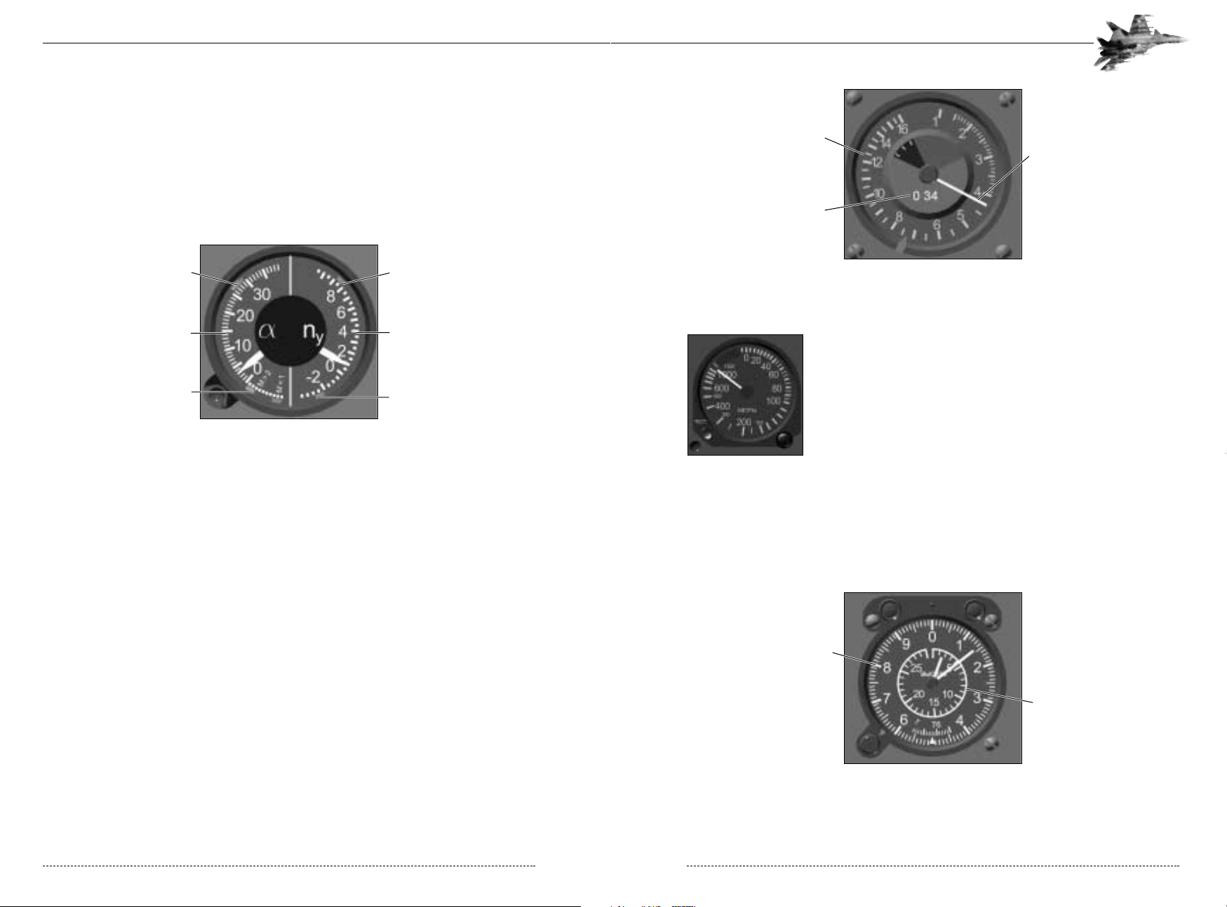
Combined G Meter & AOA Indicator
This instrument is located in the upper left corner of the Instrument Panel. The scale of the AOA
Indicator (left side of the instrument) has uniform marks in the range from -20° to 40°. The red
mark on the scale marks the maximum operational angle of attack. On the right side of the instrument is the G-Load scale uniformly marked every 2 Gs from -4 to +10g.
Airspeed Indicator & Mach Meter (ASI)
The ASI is situated to the right of the G Meter and displays the current indicated airspeed (IAS)
and Mach number. While true airspeed (TAS) measures the aircraft’s speed against a fixed point,
IAS, on the other hand, takes into account the change in air pressure at altitude and how it affects
flight. At sea level, TAS and IAS are identical. At high altitude, IAS is much lower than TAS because
of the thinner atmosphere. A Flanker flying at 350km/hr IAS will have similar flight characteristics at
any altitude. IAS, in other words, accounts for the decreased pressure at higher altitude and the
subsequent decreased lifting capability of the wing. As a result, IAS provides a near constant
measure for stall speed, regardless of altitude.
The scale of the ASI is marked from 0 to 1600 km/h and is non-linear (the values of the scale
divisions grow with increase in speed). The three-digit Mach number indicator reflects the ratio of
true airspeed to the speed of sound under the given flight conditions.
FLANKER 2.0
FLANKER 2.0
28 CHAPTER 3: Instrument Panel
Maximum Positive AOA Maximum Positve G
G Load Scale
Maximum Negative G
AOA Scale
Maximum Negative AOA
Indicated Airspeed Scale
Airspeed Indicator Needle
Mach Number
Outer Scale
(0 to 1 km)
Inner Scale
(0 to 30 km)
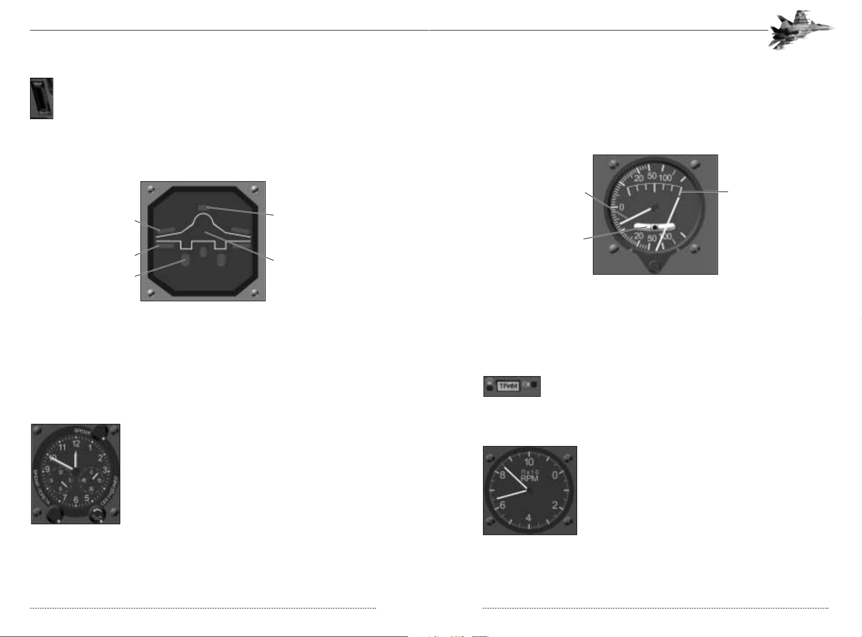
Variometer
The Variometer is situated between the Attitude Direction Indicator and the RPM Indicator and
shows your current rate of climb and turn. The scale of the instrument is non-linear ranging from
200 m/s (climb) to -200 m/s (dive). Thus, in the area of zero vertical speed the scale has the highest accuracy. The rate of turn scale ranges from 3°/sec left to 3°/sec right with a 1-degree interval.
The small ball on the sideslip scale slides in the direction of the aircraft’s sideslip. This indicator is
used to coordinate the input of rudder to help to coordinate turns. The pilot “steps on the ball”
(applies rudder on the same side as the ball) to center it in the indicator...
Neutral Trim Indicator
This indicator is located right below the Horizontal Situation Indicator. The
highlighting of the Neutral Trim Indicator means that the trimmer is in the
neutral position. As soon as you start to trim using the joystick coolie hat or
the trim control keys, the light is disabled.
RPM Indicator
The RPM Indicator is located to the left of the MFD. The scale of
the indicator is graduated from 0 to 110% in tens of percent. Two
separate needles measure port and starboard engine thrust. When
both engines are operating at the same thrust, it will appear that
only one needle is visible.
CHAPTER 3: Instrument Panel 31
Slats Indicator
The Slats (or leading edge flaps) Indicator is to the left of the Radio Altimeter. The white
portion of the bar indicates the position of the slats. The lower the white needle, the
farther the slats are released. Note that the slats on the Flanker are controlled automatically by the flight control system and configure to the optimum angle for the aircraft’s
attitude, angle of attack, speed, weight, and altitude.
Configuration Display
In the lower left-hand corner of the Instrument Panel below the Radar Altimeter is the
Configuration Display. It shows information about the positions of the landing gear, flaps, anti-FOD
screens, air brake and drogue chute (and the tailhook in the case of the Su-33). Illumination of
any indicator by a green light means that the corresponding control is in the active position, i.e.
deployed. A flashing green light means that the control is in movement. The anti-FOD screens are
automatically actuated on take-off and landing.
Clock
The clock shows the current time within
the simulation.
FLANKER 2.0
FLANKER 2.0
30 CHAPTER 3: Instrument Panel
Anti-FOD Screen
Speed Brake
Drogue Chute
Flaps
Landing Gear
Vertical Speed Indicator
Turn Rate Scale
Slip Indicator
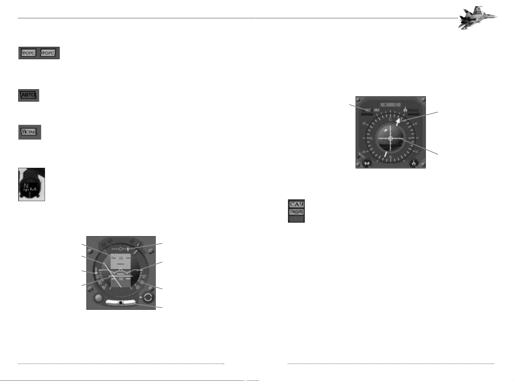
The mobile Pitch Scale and the Aircraft Datum (symbolic image of the aircraft in the center) show
the aircraft’s spatial orientation with respect to the horizon. The ADI also receives control information on the pitch angle, bank, heading, and altitude required to reach the next navigation waypoint.
This information is supplied by the navigation system, and it enables the pilot to manually fly the
Flanker and follow a specific flight plan.
Horizontal Situation Indicator (HSI)
Automatic Control System Failure Indicator
The illumination of the ACS Failure Indicator CFE (pronounced “sau,” stands
for Automatic Control System) located to the right of the HSI signifies a failure of
the Automatic Control System. This indicates a disturbance and/or failure in the
operation of Autopilot and Altitude Stabilization systems.
Hydraulic System Failure Indicator
The Hydraulic System Failure Indicator UBLHJ (pronounced “gid-ro,” stands for HYDRO) is just
below the ACS Failure Indicator. This kind of failure results in the loss of control of the flaps, slats,
and the air brake, plus diminished authority of elevator, rudder and flaperons.
CHAPTER 3: Instrument Panel 33
Afterburner Engaged Indicators
The Afterburner Engaged Indicators are right above the RPM indicator.
They are highlighted when the afterburner lights and engine RPM exceeds
100%. The word AJHC on the indicators (pronounced “fors”) which is
short for “forsazh) denotes “afterburner” in Russian.
Autopilot Engaged Indicator
Illumination of this indicator located to the right of the Configuration Display designates operation of the Automatic Control System in autopilot mode. The Russian
FDNJ (pronounced ‘af-to’) denotes autopilot, and is toggled by the A key.
Altitude Stabilization Indicator
The Altitude Stabilization Indicator is to the right of the Autopilot Engaged Indicator
below the Barometric Altimeter.The Russian Y-CNF< (pronounced ‘ash-stab’.)
denotes that the Automatic Control System is in altitude stabilization mode. Toggle
the altitude stabilization mode with the H key.
Magnetic Compass
The forward frame of the cockpit canopy houses three rearview mirrors and the
Magnetic Compass. The compass consists of a ball with a scale, which is
enclosed in a casing and plunged in a liquid. The scale on the ball is marked in
30° increments and has designations of the cardinal points (North, West, South
and East).
Attitude Direction Indicator (ADI)
In the center of the Instrument Panel just below the Weapon Readiness Indicator is the Attitude
Direction Indicator (ADI) or artificial horizon. It is the main navigational instrument, especially in
zero visibility conditions.
FLANKER 2.0
FLANKER 2.0
32 CHAPTER 3: Instrument Panel
Pitch Scale Required Heading Indicator
Aircraft Datum
Bank Scale
Slip Indicator
Required Bank Indicator
Required Altitude Indicator
Required Pitch Indicator
Distance To Beacon
Heading to Beacon
ILS Lines
Combat Instrumentation
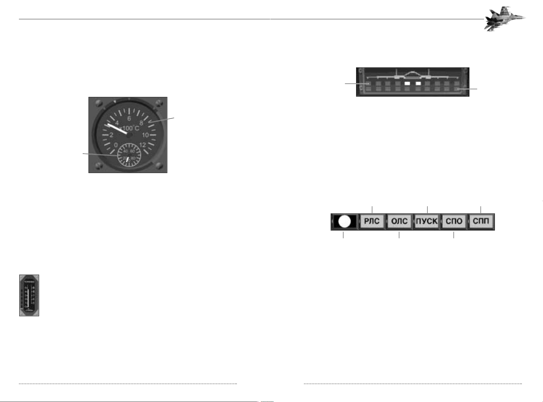
Weapons Readiness Panel.
This indicator is located just below the HUD and shows the location and readiness of the available
weapons hanging on 10 underwing and fuselage pylons. The illuminated lights in the upper row
indicate the presence of weapons on the pylons, and those in the lower row the readiness of the
corresponding weapons to instant use. Note that such readiness is governed not only by the
selection of the weapon, but also by the specific combat situation.
Master Warning Panel Failure Lights
Located just below the Weapons Readiness Panel, the Warning Panel provides visual and audible
alerts to system failures and launch warnings. It consists of five indicators:
• Master Warning Light: The flashing red Master Warning Light accompanied by beeps
attracts your attention to vital information such as ground proximity, stall, damage to any systems
of the aircraft, low fuel, illumination of your aircraft by radar and others. The Master Warning
Light is the main form of notification when the following system damage failures, or other events
occur: gear up of down, launch authorization, Gmax or AOA max, out of fuel, or minimum or
maximum speed reached.
• HKC(“rls”) Radar Failure
• JKC(“ols”) Electro-Optical System Failure
• GECR(“pusk”) Missile Launch Warning
• CGJ(“spo”) Radar Warning System Failure
• CGG(“spp”) Missile Launch Warning System Failure
CHAPTER 3: Instrument Panel 35
Jet Pipe Temperature Indicators
The two indicators located to the right of the HSI show jet pipe temperature of gases at the turbine exhaust of both AL-31F engines. Each indicator consists of two circular scales, the large
scale ranging from 0 up to 1000° Celsius and showing the temperature in hundreds of degrees.
The small scale renders more precise the reading taken from the large scale and has a range of
100°C in tens of degrees. Exact temperature is read by combining the two scales.
Maximum Engine Temperature Indicators
Located just below the Jet Pipe Temperature Indicators are the Max Engine Temperature
Indicators. Critical jet pipe temperatures are symptoms of impending engine failure, engine compressor failure, missile strike, etc.
A failure of the power plant often leads to a spontaneous increase of gas temperature at the turbine exit and a drop in RPM. This situation is immediately reflected on the RPM Indicator and the
Jet Pipe Temperature Indicators.. An engine on fire or suffering catastrophic failure will shut down
automatically and a powerful halogen extinguisher will be released into the engine area.
Fuel Gauge
The Fuel Gauge is to the right of the Jet Pipe Temperature Indicators. It indicates
total fuel remaining in the tanks. The vertical scale of the instrument is marked in
tons and uses two scales to measure from 0 to 9 tons. The scale on the left marks 0
to 5 tons; the scale on the right marks 5 to 9 tons.
At the top of the Fuel Gauge is the NJHKBJ light (denotes “fuel” in Russian, should
be pronounced “top-li-vo”). When this is highlighted, you are on your reserve fuel,
and its definitely time to return to base as things could be going awfully quiet soon.
But don’t panic too much as the reserve guarantees successful flight to the nearest diversion
airfield in case a landing is impossible on the initial airfield (runway destroyed, poor visibility, etc.).
FLANKER 2.0
FLANKER 2.0
34 CHAPTER 3: Instrument Panel
Inner Scale
Outer Scale
Position Loaded Lights
Position Active Lights
Master Warning Light
Radar Failure
Missile Launch
Warning
Missile Launch Warning
System Failure
EOS Failure
Radar Warning
System Failure

Active Jamming Indicator
Below the Chaff/Flare Counter is the Active Jamming Indicator FG (“ap”). This
indicator shows activity of the built-in and/or additional Sorbtsiya active jamming
system. If the indicator is not highlighted, your active jamming system is damaged
or turned off. The active jamming system is toggled by the E key.
MULTI-FUNCTION DISPLAY (MFD)
The Multi-Function Display (MFD) dominates the right-hand side of the instrument panel. The
MFD is the most versatile of all instrumentation in the Flanker, displaying different types of data
depending on the selected avionics mode. The MFD generally displays a “top down” view, with
the symbology and objects displayed varying depending on the selected avionics mode.
Each avionics mode is described, complete with illustrations of the MFD symbology, in the
Avionics chapter.
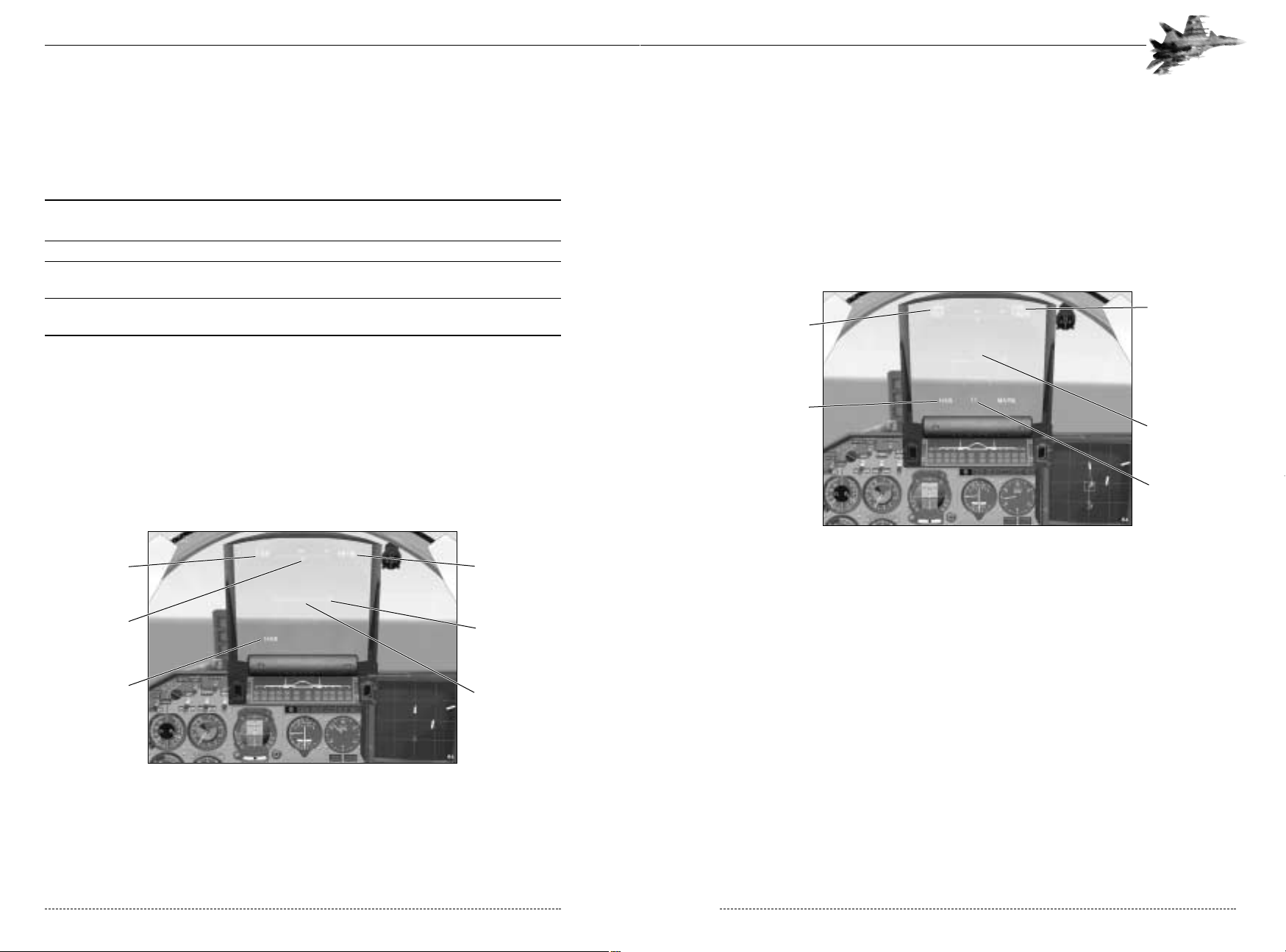
HEAD UP DISPLAY (HUD)
The most important multi-function instrument of the Flanker is the Heads-Up Display (HUD). The
HUD displays a wide variety of flight attitude, navigation, weapons, and targeting information
depending upon the selected avionics mode. Generally speaking, the HUD always displays your
airspeed (in km/hr), your altitude (in meters), your heading, and your flight attitude (pitch and
bank). The altitude display will vary between MSL (altitude above mean sea level) and radar AGL
(altitude above ground level). When displaying AGL, the symbol H (the Russian letter “R” for
“Radar Altimeter) appears next to the altitude display. Radar altimeter data is valid only when
banking less than 45 degrees or pitching less than 70 degrees. The HUD also displays the currently selected avionics mode in the lower left corner. By default, the mode name is displayed in
Russian; you can configure this to English via the Options menu. The possible modes are:
CHAPTER 3: Multi-Function Display (MFD) 37
Chaff/Flare Counter
Below the MFD is the Chaff/Flare Counter, which shows how many APP-50 combined chaff and flare dispensers remain at your disposal. The initial value of the
counter is 32 for the Su-27 and 51 for the Su-33. The counter reads zero if the
chaff/flare deployment system is damaged or you’ve run out of dispensers. Pressing the ALT-Q
toggles the continuous dispenser on or off. When activated, the dispenser will deploy chaff and
flares until either the player turns the dispenser off or the supply of chaff and flares is exhausted.
Threat Warning Display
In the lower right-hand corner of the cockpit is the Threat Warning Display (TWD). It depicts
information on enemy illumination sources detected by the SPO-15 ‘Beryoza’ Radar Warning
System. Such sources can be enemy aircraft, radar of SAM installations, AWACS, and so on.
Lights surrounding the aircraft’s silhouette show the approximate bearing of the illumination
source: if the aircraft falls within radar coverage, the corresponding light flashes at a frequency
characterizing the periodicity of illumination, and the audio alarm beeps. In the event of a “lock on”
the red Lock-On Indicator is continuously illuminated.
In the lower part of the TWD are 5 lights indicating the type of radar that has locked onto your aircraft. The Radar Warning System provides for the identification of the following types of radar:
1 - airborne radar
2 - radar of a long-range SAM system
3 - radar of a mid-range SAM system
4 - radar of a short-range SAM system
5 - early warning radar (airborne or ground-based).
FLANKER 2.0
FLANKER 2.0
36 CHAPTER 3: Instrument Panel
Ranging Lines
Your Aircraft Position
Mode-Specific Display
Ranging Scale
Threat Bearing Indicators
Radar Type Indicators
Lock-On Detected
CHAPTER 4: Introduction to Avionics & Combat Systems 39
INTRODUCTION TO AVIONICS &
COMBAT SYSTEMS
Flanker 2.0 offers a complex and realistic portrayal of the real-world avionics suite found in the
Su-27 and Su-33. By Western standards, these systems are generally regarded as inadequate,
creating high pilot workload. To get the most out of the Flanker, you must learn how to operate its
systems and how to cope with its design limitations.
All HUD displays fall into one of three categories: navigation, air-to-air combat, or air-to-ground
combat. Sub-modes organize and display different types of information. Generally speaking, it’s
not necessary to utilize every sub-mode for each category; however, each sub-mode is designed
for a particular task.
Russian vs English Displays
To create the most authentic simulation of a Russian aircraft, all displays and HUD indicators
default to the Russian language with Cyrillic characters. You may, however, switch the displays
between English and Russian language in the Options menu under “miscellaneous.” Please note:
regardless of the language used, all displays will still use metric units. Altitude is measured in
meters and airspeed is measured in Kilometers per hour.
CHAPTER 4
Avionics and Combat Systems
CHAPTER 4
Avionics and Combat Systems
RUSSIAN DESIGNATIONS ENGLISH DESIGNATIONS PURPOSE
YFD (NAV) NAV (Navigation) Basic navigation mode, heading + stopwatch.
SUBMODES: SUBMODES:
VFHY (MARSH) ENR (En-route) Follow flight path.
DJPD (VOSV) RTN (Return) Return to selected airfield.
GJC (POS) LNDG (Landing) Land on selected airfield. ILS approach.
YFD (DVB) BVR (Beyond Visual Range) Engage airborne targets at long ranges.
SUBMODES: SUBMODES:
J<P (SKAN) SCAN (Scan) Scans a mximum of 24 contacts.
CYG (SNP) TWS (Track While Scan) Tracks 8 contacts while scanning up to 16 contacts.
(DRLO) AWACS Displays contacts from AWACS datalink.
FNR (ATK) ATK (Attack) One target locked-up.
<D< (BVB) CAC (Close Air Combat) Dogfight at close range.
CNH (STR) BORE (Radar Bore Site) Aim using forward looking bore site of
radar beam.
ABJ (FIO) LNGT (Longitudinal Aim using the selected missile guidance system at
missile aiming) visual ranges.
IKTV (SHLEM) HMTD (Helmet-Mounted Engage agile targets using helmet-
Target Designator) mounted target designator.
PTVKZ (ZEMLYA) GND (Ground Attack) Destroy ground targets.
GH (PR) LA (Shoot) Authorized to fire weapon.
JND (OTV) NO LA (Don’t Shoot) Not Authorized to fire weapon.
Each avionics mode is described, complete with illustrations of the HUD symbology, in the
Avionics chapter.
FLANKER 2.0
FLANKER 2.0
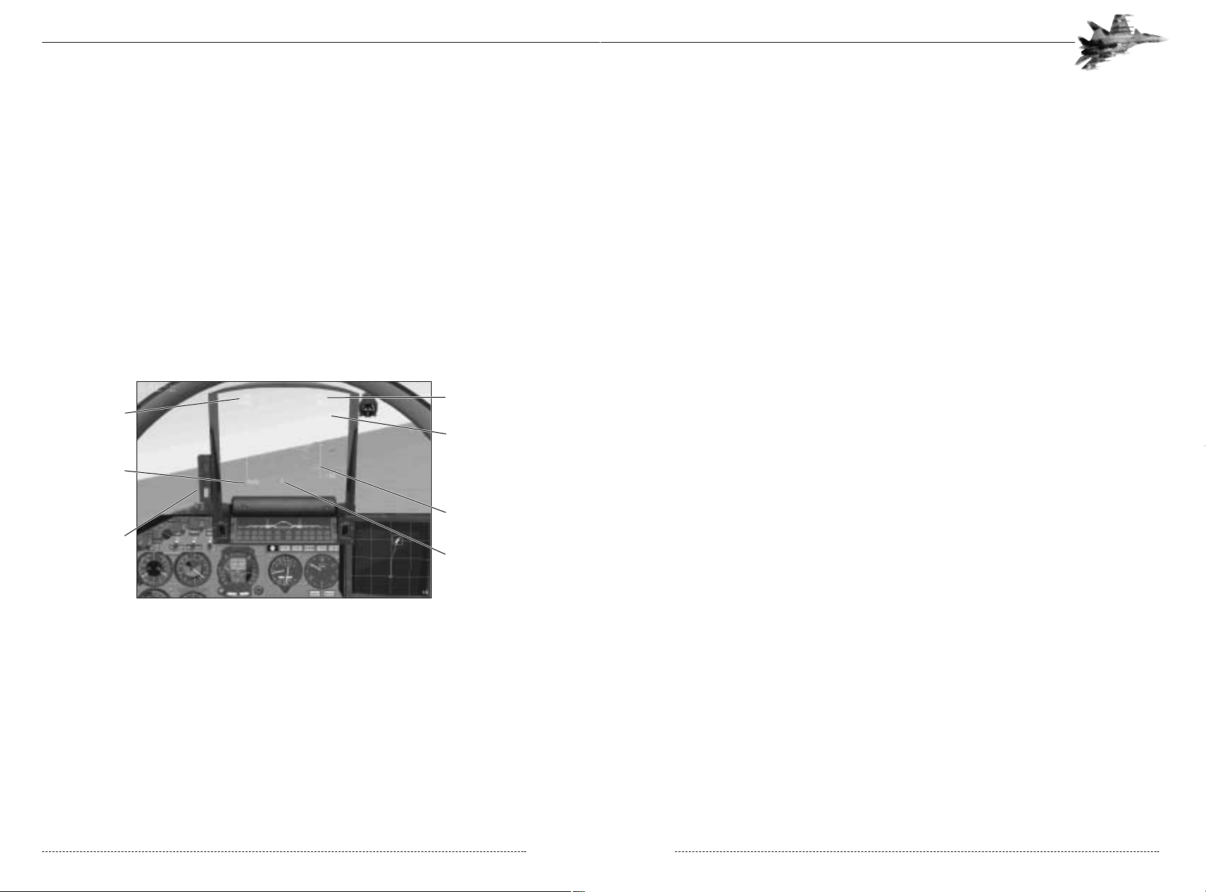
38 CHAPTER 3: Multi-Function Display (MFD)
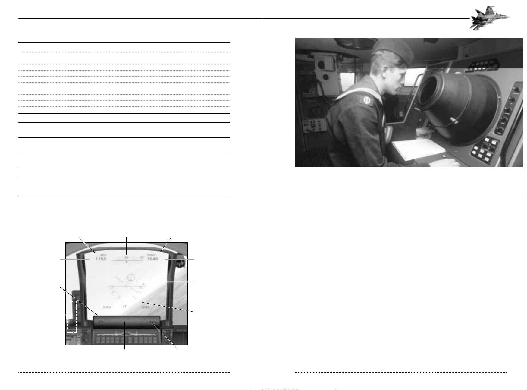
YOUR SPEED
YOUR ALTITUDE
FLIGHT PATH MARKER
CURRENT PITCH &
BANK DATA
HUD MODE
GLIDE PATH INDICATOR
LIGHTS (SU-33 ONLY)
RANGE TO SELECTED OBJECT
(TARGET, AIRFIELD, NAV POINT)
SUBMODE
REQUIRED SPEED HEADING REQUIRED ALTITUDE
Defense Visual Information Center - Department of Defense
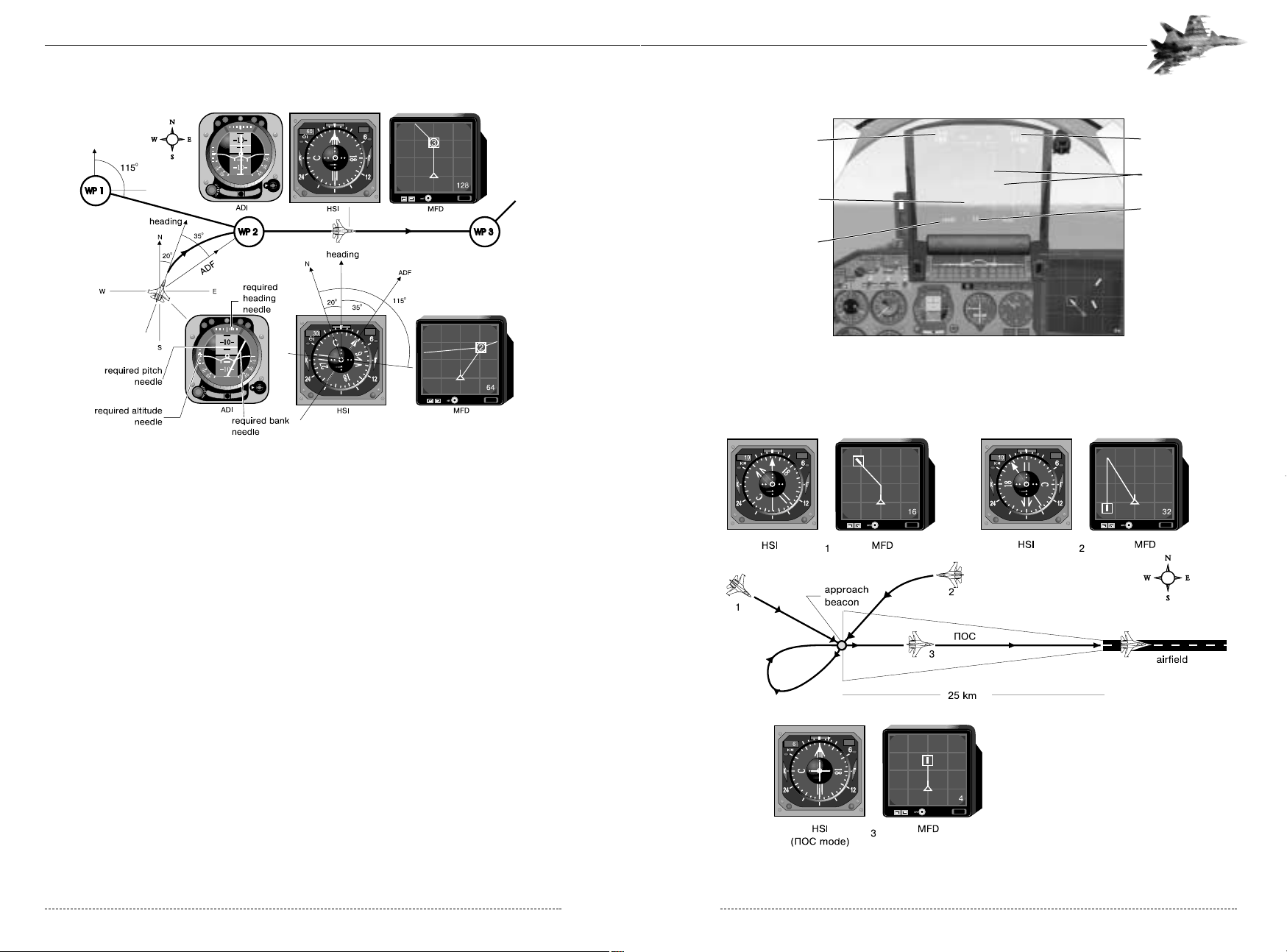
VFHI (ENR) - Enroute Submode
The VFHI (ENR) submode is the primary navigation submode, enabling the pilot to fly the predetermined mission flight profile. Select it by pressing the 1 key while in the initial NAV or Piloting
mode. Each waypoint is characterized by its coordinates on the ground, its altitude, and the
desired airspeed for that leg of the trip. This mode displays the required speed and altitude of the
waypoint in small characters located above the actual speed and altitude readouts of the aircraft.
A circle or navigation reticle, inside the HUD points the way to the next waypoint. Manoeuvre the
aircraft to center the navigation reticle in the HUD and you’re heading directly to the next
waypoint. Numbers in the center of the HUD’s bottom edge indicate the distance to the next
waypoint in kilometers.
4-2: The VFHI (ENR) Submode
Backup Instruments
The instrument panel also provides navigation information. The MFD symbolizes your position, the
waypoint , and the desired flight path to the next selected waypoint. The ADI yellow predictor bars
(“needles”) mark the desired bank and pitch angles while the HSI shows the required heading
and distance to the next waypoint. In general, if the HUD becomes unservicable, you can still navigate using the instrument panel.
The VFHI (ENR) submode provides no combat information. Generally speaking, select this
mode, set your course, and then select a more appropriate combat mode. Occasionally return to
VFHI (ENR) mode to verify your flight path. Press the ~ key to cycle through waypoints.
CHAPTER 4: Navigation 41
NAVIGATION
The navigation modes are your primary means of finding your way around the simulated battlefield. There are four navigation submodes.
RUSSIAN PRONOUNCED ENGLISH MODE TYPE PURPOSE
DESIGNATION DESIGNATION
YFD “nav” NAV Piloting Visual navigation with a compass and
stopwatch
VFHI “marsh” ENR Enroute Enroute navigation
DJPD “vosv” RTN Return Return to the Initial Approach Fix at
the home airbase.
GJC “pos” LNDG Landing Activates the Instrument Landing System (ILS)
and autoland feature (for carrier operations.)
To select the navigation category press the 1 key. This selects the default navigation mode, Piloting.
Cycle through the various individual navigational submodes by hitting the 1 key repeatedly.
YFD–(NAV) – Piloting Mode
The piloting mode is the initial navigation mode, automatically displayed whenever you first press the 1
key while in another mode. This mode provides only minimal information. The HUD shows airspeed,
altitude, and flight attitude information while the MFD shows airfields and the Admiral Kuznetzov
aircraft carrier, if present. Use this mode for free-form flying without any pre-determined plan.
4-1: The YFD (NAV) - Piloting Hud
FLANKER 2.0
FLANKER 2.0
40 CHAPTER 4: Navigation
Airspeed Altitude
Pitch Angle
Aircraft Datum
Heading
NAV Mode Selected
Required Airspeed
Required Altitude
Waypoint Steering Cue
Distance to Waypoint
On Route Mode Selected
4-4: The DJPD (RTN) - Return Submode
You select the DJPD (RTN) submode by pressing the 1-key twice from the initial NAV mode. You
may cycle through the available runways and their IAFs by pressing the ~ key.
4-5: Reading the DJPD (RTN) - Return Submode Instrumentation
CHAPTER 4: Navigation 43
4-3: Reading the VFHI (ENR) Submode instrumentation
In figure 4.3 the aircraft on approach to waypoint 2 is misaligned by about 35 degrees to the left.
This is reflected on the HSI (see the instruments at the bottom of the figure): the current heading
is 20 and the ADF arrow (the narrow needle) reads 55 degrees. The distance to waypoint 2 is
30km (upper left corner of the HSI). The desired radial, the desired flight path from waypoint 1 to
waypoint 2, is shown by the flight path marker (the wide needle). In other words, the ADF needle
points directly to the next waypoint while the flight path marker points to the pre-programmed
flight path to that same waypoint.
The ADI also shows the misalignment between the aircraft’s heading and the next waypoint. The
required bank needle points to the right, indicating the aircraft needs to turn to the right to reach
the next waypoint. If the aircraft were on course, the needle would point straight up. The required
altitude needle on the left of the ADI shows that the aircraft is quite close to the desired altitude.
If the aircraft is on the planned flight path, as is the aircraft between waypoints 2 and 3 in the
same figure, then the wide and narrow arrows on the HSI are aligned and pointing straight up.
Likewise, the required bank needle on the ADI is also pointing straight up.
DJPD (RTN) - Return Submode
The DJPD (RTN) submode directs you to the Initial Approach Fix (IAF) for the runway you are
landing at. Think of the IAF as the last waypoint before reaching the airbase, where you will intercept the Instrument Landing System (ILS) and begin your approach. For all intents and purposes,
DJPD (RTN) is identical to VFHI (ENR) except that DJPD (RTN) only has one waypoint: the
IAF for the runway.
FLANKER 2.0
FLANKER 2.0
42 CHAPTER 4: Navigation
Required Airspeed Required Altitude
Distance to Approach Point
Steering Cue
Return Mode Selected
ILS Bars
RADAR AND ELECTRO-OPTICAL SYSTEM
The weapons control system (WCS) of the Su-27 and the Su-33 integrates the weapon and target
data and parameters from the following components:
• The Zhuk-27 or Miech-33 airborne radar;
• The 36-Sh Electro-Optical System (EOS);
• The onboard weapons management software;
• Individual weapon targeting hardware and software;
• The data presentation system (MFD and the HUD);
• The Parol (Password) Identification Friend or Foe (IFF) interrogator which processes signals from
air and ground installations equipped with pertinent transponders;
• The Helmet-Mounted Target Designator (HMTD);
• Target data feed from AWACS.
Zhuk-27 radar (Su-27)
The Phazotron Zhuk-27 (Beetle) coherent pulse-Doppler jam-proof radar is fitted with a twist
cassegrain antenna of 700 mm in diameter and has the following features:
Air-to-air mode
• Look/down-shoot/down capability;
• Range-while-search of up to 24 contacts;
• Track-while-scan of up to 8 contacts;
Miech-33 radar (Su-33)
The Phazotron Miech-33 (Shield) is also a coherent pulse-Doppler jam-proof radar with the same airto-air characteristics as the Zhuk-27, but additionally offers a powerful air-to-surface mode.
Air-to-air mode
• Look/down-shoot/down capability;
• Range-while-search of up to 24 contacts;
• Track-while-scan of up to 8 contacts;
Air-to-surface mode
• Real beam ground mapping;
• Doppler beam sharpening;
• Synthetic aperture;
• Map enlargement/freezing capability;
• Detection and tracking of moving ground or seaborne targets;
• Air to surface ranging.
CHAPTER 4: Radar and Electro-Optical System 45
When flying towards the IAF, the wide arrow on the HSI always indicates he bearing from the beacon to the selected airfield and normally is the same as the runway heading. Figure 4-5 illustrates
the readings of the HSI and the MFD for three aircraft with different positions relative to the
approach beacon. Aircraft 1 is 10km from the beacon and flying a heading of 135, on track to the
IAF. Aircraft 2 is 10km from the IAF, flying a heading of 270. The misalignment between the current
heading and the required heading is 35 degrees. In other words, the pilot must turn 35 degrees to
the left to fly directly to the IAF. Aircraft 3 is flying the runway heading, between the runway and the
IAF. In this case, the MFD shows only a straight line from the runway to aircraft marker.
When the aircraft reaches the IAF, the navigation software automatically switches to the GJC
(LNDG), or landing, submode.
GJC (LNDG) Landing Submode
You can, however, switch directly to Landing submode by pressing the 1 key repeatedly until the
GJC (LNDG) indicator is displayed on the HUD. If the airfield is equipped with an ILS, the
Glideslope and Localizer bars are displayed. A vertical velocity scale will appears on the right side
of the HUD. The ideal touchdown should occur at a sink rate of 1 to 1.5 m/s.
4-6: The GJC–(LNDG) Landing Submode with ILS
For more information on landings, see the section on landings in Chapter 5, Ground School and
the appropriate training missions in Chapter 7, Training.
FLANKER 2.0
FLANKER 2.0
44 CHAPTER 4: Navigation
Required Airspeed
Required Altitude
Vertical Velocity Scale
Current Vertical Velocity
Distance to Runway
Return Mode Selected
AOA Indexer

To toggle the EOS, press the O key. The EOS Cue N (stands for ‘Thermal’) on the left side of the
HUD indicates that the EOS is active If the EOS Cue does not appear at all, this indicates that the
EOS is either damaged or not correctly selected.
The EOS, radar, or a missile’s seeker can be slaved to the pilot’s helmet-mounted target designator (HMTD) allowing the pilot to target simply by moving his head in the direction of the enemy
aircraft. This is extremely convenient for acquiring agile targets at visual ranges.
Since the principles of using the radar and the EOS are practically the same, we describe these
principles for the various combat modes in the same place, pointing out distinctions as needed.
Scan Cone Basics
To understand how the radar/EOS searches for targets, imagine walking through a forest with a
flashlight on a pitch-black, moonless night. You can only see objects illuminated by the flashlight
beam, and the beam grows weaker as it extends from the light bulb. This essentially describes the
problems using radar to search for targets. In simple terms, the radar extends something like a
cone in front of the transmitter. The farther it goes, the bigger the cone gets. Objects outside of
the cone will pass undetected. As a result, it is necessary to turn the aircraft occasionally and to
“slew” the scan cone using the Shift - ; (up)Shift - . (down) Shift - ‘ (left)Shift - / (right) keys,
much like moving the flashlight around the darkened forest.
Objects inside the cone will reflect radar energy back toward the transmitter. But, radar waves lose
power as they travel. If they travel far enough, they eventually dissipate. Consequently, contacts at
long range may not reflect enough radar energy; the reflected waves dissipate before making it
back to the transmitter. Therefore, if the radar energy can travel 150km, bounce off a target, and
return 150km to the source, then the radar energy is also capable of travelling at least 300km in a
straight line. This means that the enemy can detect your radar transmissions from well outside of
your effective search range!
The EOS works similarly, except that it is a passive system; instead of looking for reflected radar
waves, it looks for heat emitted by targets. As a general rule, hotter targets (fighters using afterburner) can be detected further away. Also, rear-aspect targets (with the heat source pointed at
the EOS) will generally be detected further away than nose-aspect targets (since the enemy aircraft is blocking the view of the engine exhaust).
CHAPTER 4: Radar and Electro-Optical System 47
Radar Cross Section (RCS) of the target, or the size of the reflecting surface of the target, has
a substantial impact on radar detection performance. In general, large targets reflect more radar
energy, so a B-52 can be detected farther away than an F-16. For a target with an effective RCS
of 3 m2 (a typical sized fighter) the Zhuk-27 has a maximum detection range of 150 km (93 miles)
when facing the target’s forward hemisphere and 55 km (34 miles) when facing the target’s
rear hemisphere.
The radar transmits radio pulses of nearly equal frequency (within the X-band) and phase (coherent radiation). The radar measures the range to the target by timing how long it takes for the
reflected waves to return to the transmitter. The greater the range, the longer it takes the waves to
return. When the pulses are reflected from a moving target, the frequency shifts due to the
Doppler effect. Pointing the radar at the ground, naturally, results in lots of radar reflections
appearing on the scope. These returns are called ground clutter. Most modern radar systems
take advantage of the Doppler effect and filter out any returns that are stationary, thus filtering out
the extra returns from ground clutter. This does have one side effect, however, an airborne target
that has no movement relative to the transmitter appears stationary and is filtered out. This condition typically occurs when the target moves perpendicular to the transmitter, and therefore
appears stationary (in terms of how fast the transmitter is closing on the target). This effect is
called “beaming” and is an effective defense against airborne radars.
You toggle the radar by pressing the I key. The Radar Cue B (Russian “I”, stands for ‘illumination’)
on the left of the HUD indicates that the radar is active. If the Radar Cue does not appear when
you enable the radar, this means that latter is damaged.
36-Sh Electro-Optical System
See EOS The radar is backed up by the 36-Sh electro-optical system (EOS) designed by the NPO
Geophysica. The EOS can acquire thermally contrasting targets with high accuracy. It combines a
laser rangefinder (effective tail-on range of 8 km/5 miles) and Infra-Red Search and Track (IRST)
system (maximum effective range of 50 km/31 miles). These use the same optics, which consist of
a periscopic system of mirrors and an articulated glass sensor ball mounted centrally in front of
the windscreen. The sensor ball moves in elevation (-15° down and +60° up) and in azimuth (60°
left and 60° right of center, respectively). The information update rate depends on the field of view
size and varies from 2 (search in wide area) to 0.05 (autotrack mode) seconds.
The EOS operates passively (emits no detectable signal) by receiving infra red emissions from the
target. This allows the pilot to prepare a surprise attack on the enemy. Maximum detection ranges
depend on the attack geometry. It changes from 15 km for forward-hemisphere attacks to 50 km
for attacks in the rear hemisphere. The range to a target can be accurately measured only at relatively close distances (from 200m to 3 km). In order to measure distances outside laser range
when a target is locked (TAB Key) the radar sends short strobe bursts or pules towards the contact. Once the contact comes within 9 Kilometers, the strobe pulse ceases and the laser
rangefinder takes over. These pulses are extremely short and difficult to detect with accuracy, thus
providing little opportunity to locate the source. You mainly use the EOS to provide targeting data
for air-to-air missiles with an IR seeker head and for tracking targets in a guns fight.
FLANKER 2.0
FLANKER 2.0
46 CHAPTER 4: Radar and Electro-Optical System

Air-to-Air Mode Summary
The following table lists the different avionics modes available for air-to-air combat. Note that they
fall into three categories: beyond visual range, close air combat, and longitudinal missile aiming.
FLIGHT / COMBAT MODE RUSSIAN ENGLISH KEY PURPOSE
Beyond Visual LD<-J<P BVR – SCAN 2 Acquire up to 24 tar
Range - Scan gets at 25 km to 150 km ranges.
Beyond Visual Range -Track LD<-CYG BVR - TWS 2 Tracking up to 8 contacts while scanning
While Scan up to 16 more.
Beyond Visual Range - LD<-LHKJ AWACS 2 Using AWACS information for attacking
AWACS Datalink targets when radar and EOS is off.
(Requires AWACS)
Close Air Combat – <<<-DC CAC – VS 3 Dogfight at ranges from visual to 25 km
Vertical Scan
Close Air Combat – <D<-CNH CAC – BORE 4 Aim using forward looking bore site of
Radar Bore Site radar beam.
Close Air Combat – <D<-IKTV CAC – HMTD 5 Aim using helmet-mounted target
Helmet designator.
Longitudional Aiming ABJ LNGT 6 Aiming using a missile’s seeker at ranges
from visual up to max IR/active range
of missile
Attack LD<-FNR BVR-ATK Tab Auto-tracking one target (Target Locked).
<D<-FNR CAC – ATK
ABJ-FNR FIO – ATK
LD< (BVR) Beyond Visual Range Mode
In LD< (BVR) Beyond Visual Range Mode, both the radar and the EOS scan in a limited area - the
scan cone has angular dimensions of 10° in the vertical plane (elevation scan angle) and 60° in the
horizontal plane (azimuth scan angle). You can move the radar/EOS scan zone within the gimbal
limits of the antenna/seeker. The scan zone dimensions of the radar are 120° x 120° , the EOS
dimensions are 120° horizontal, 60° up and 15° down (see the figure below). The radar beam
scans an area 2.5° tall, requiring four passes to the cover the entire scan cone. Each pass takes
about 0.5 seconds. Information on each radar contact, therefore, is updated every two seconds.
CHAPTER 4: Air-to-Air Combat 49
AIR-TO-AIR COMBAT
During an attack on an airborne target the pilot usually goes through the following steps: search,
locate, track, identify, and attack. He can accomplish these steps both with and without the radar
and/or the Electro-Optical System (EOS) . The selection of one or other type of weapon mainly
depends on the range to the target and the possibility of tracking the target using the onboard
radar or EOS.
The following table describes the main air-to-air HUD:
The table below is a summary of the keys you will often use in air to air combat.
KEY ACTION
I Toggle radar.
O Toggle EOS.
`
Select next AWACS contact on Multi-Functional Display (MFD)
Tab Place designated contact in Track While Scan from Scan
Ctrl-Tab Remove tracked contact from Track While Scan
Tab Lock tracked target to Attack Mode
Tab Lock/unlock target to Attack Mode in CAC submodes
; (Semicolon) Move HUD target designator UP
, (Comma) Move HUD target designator LEFT
. (Period) Move HUD target designator DOWN
/(Slash) Move HUD target designator RIGHT
Shift - ; (Semicolon) Move radar/EOS scan zone UP in BVR modes
Shift -, (Comma) Move radar/EOS scan zone LEFT in BVR modes
Shift -. (Period) Move radar/EOS scan zone DOWN in BVR modes
Shift - /(Slash) Move radar/EOS scan zone RIGHT in BVR modes
Ctrl+I Center radar antenna/ IRST ball
-(Minus) MFD/HUD Zoom in
+(Plus) MFD/HUD Zoom out
D Cycle through weapons
C Enable/disable cannon
Ctrl+V Toggle Salvo mode
Ctrl+W Jettison weapons/Load Weapons, step-by-step
FLANKER 2.0
FLANKER 2.0
48 CHAPTER 4: Air-to-Air Combat
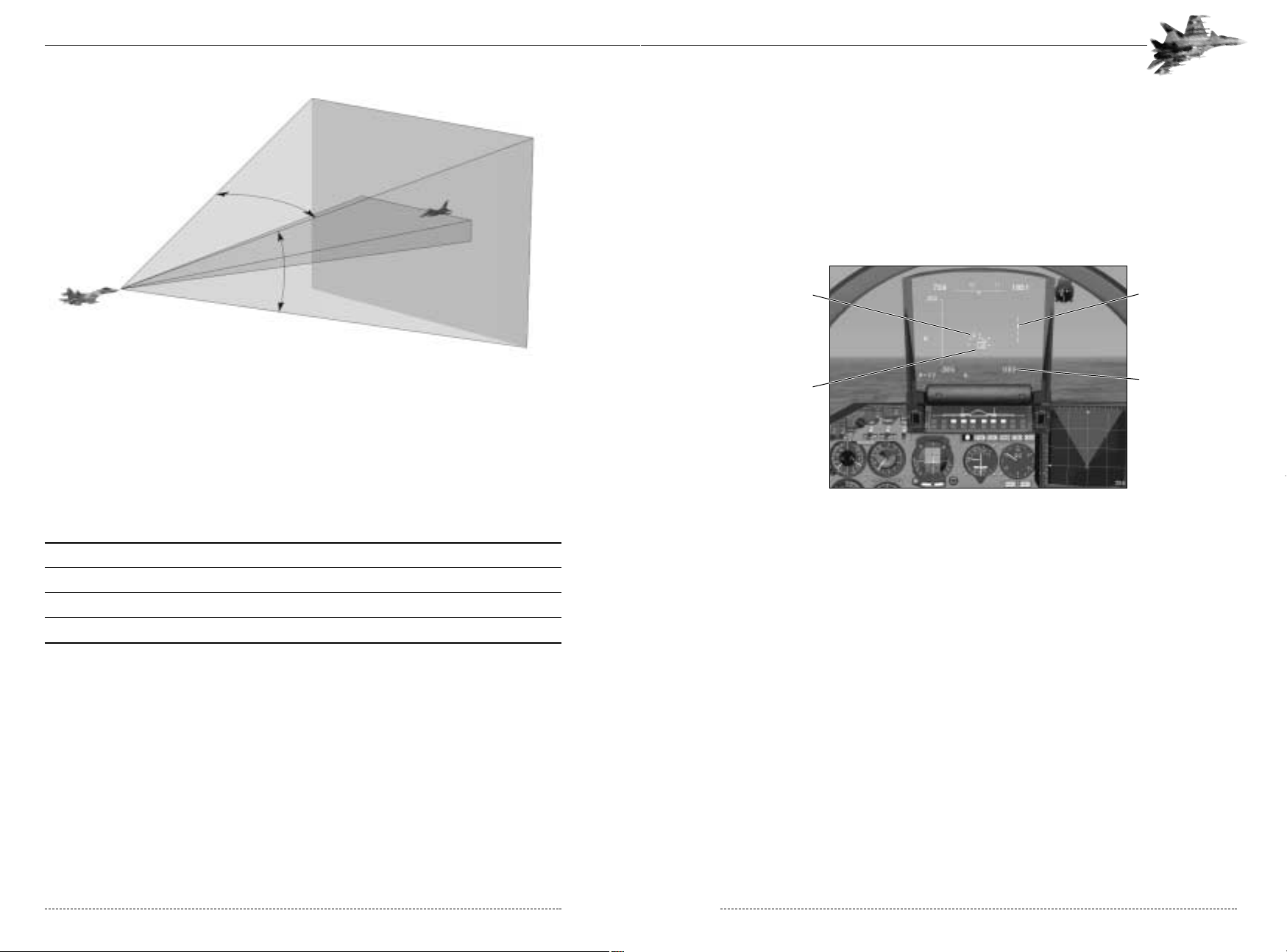
LD< – J<P (SCAN) Scan Submode
Pressing the 2 key selects LD< (BVR) mode in the J<P (SCAN) sub-mode of operation. This is
your primary, long-ranged search mode. It detects contacts (depending on RCS) from 25 to
150km away, displaying up to 24 contacts on the HUD. This mode does not provide any detailed
information about a specific contact. You’ll know the azimuth (how far the contact is off your nose)
and distance. You can also establish the contact’s elevation by the correlating the image return
and scan beam “illuminator” on the right side of the HUD.
4-8a: J<P (SCAN) Submode
To gather more information about specific contacts of interest, steer the HUD target designator
box over the desired contact (using the joystick coolie hat or the keyboard controls). Designate
the target by pressing Tab key. If the contact is within the track parameters of the radar, the HUD
switches to Track While Scan submode and the MFD will now display the designated contact.
Aspect information relating to the contact can now be viewed on the MFD. Alternatively, pressing
the 2 key immediately selects the eight closest contacts and switches to Track While Scan mode.
You cannot enter Track While Scan mode without designating at least one contact in Scan mode.
LD< – CYG (TWS) Track While Scan Submode
The
CYG
(TWS) Track While Scan submode focuses the radar/EOS “attention” on up to eight
contacts while continuing to scan and display range, azimuth, and elevation information on up to
16 others. The contacts on the MFD in TWS are continuously tracked by the radar.
On the HUD, a “tracked” contact changes from a dash to a small triangle. On the MFD, enemy
aircraft are displayed by triangle-like symbols, friendly aircraft are represented by circular symbols
and each tracked contact symbol has an aspect vector angle indicating direction and position relative to your aircraft. The MFD shows a top-down view of the area around your aircraft. Your
Flanker’s position is indicated by the aircraft symbol. The number in the upper corner of the MFD
indicates the distance in kilometers from the bottom edge of the MFD to the top edge. The closer
contacts are to the top edge, the farther away they are from your aircraft.
CHAPTER 4: Air-to-Air Combat 51
In BVR Mode, the radar antenna is stabilized in roll and pitch. This means that the direction of the
antenna axis does not change when the aircraft banks, pulls up or dives, providing that the aircraft
manoeuvres do not exceed the gimbal limits of the antenna. Unlike in many Western aircraft, the
beam shape of the Su-27’s radar is fixed and cannot be changed. The maximum detection
depends on the target’s characteristics (geometry, aspect angle, radar reflectivity, etc.). Typically,
the radar can detect a medium-size target such as a MiG-29 at a range of about 100-120 km.
Large targets such as strategic bombers can be detected at distances up to 150 km.
TARGET MAXIMUM DETECTION RANGE IN SCAN SUB-MODE, KM
B-52 150
F-111 80
F-16 50
F-117 @10
As with the radar, the field of search of the electro-optical system is stabilized in roll and pitch. The
EOS can detect medium-size targets located up to a maximum of 50 km. But, as described above,
cannot accurately measure the range to a target beyond 5 km.
Tracking data appears on both the HUD and the MFD, depending on the mode and submode
selected. In most cases, the MFD shows a top-down view of the area around your aircraft. Your
current position is indicated by the small aircraft symbol; the number in the corner indicates the
distance from the bottom edge to the top edge in kilometers. HUD and MFD symbology appropriate to each mode and submode are described in the following sections.
LD< (BVR) mode has three submodes of operation: Scan, Track While Scan, and Attack. The
following sections describe each mode.
FLANKER 2.0
FLANKER 2.0
50 CHAPTER 4: Air-to-Air Combat
Contacts
Range to Selected
Contact
Scan Sub Mode
Selected Contact
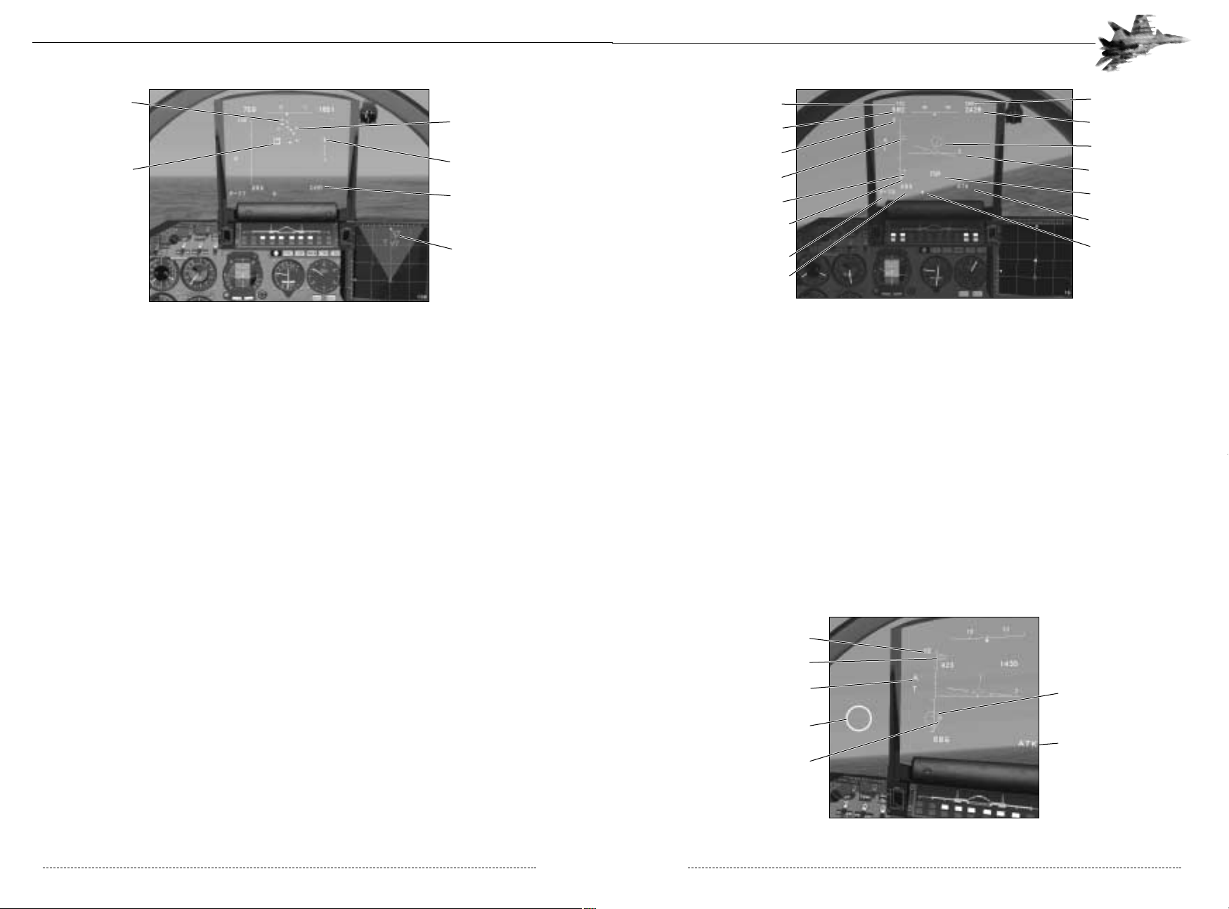
4-15: Autotrack Symbology with Radar Lock
Green lights on the Weapon Readiness Panel indicate which missiles at each weapons station are
ready for launch. The MFD displays a top-down view of the target, its aspect angle, and distanceinformation about the target. When you are tracking the target using the radar, target information
may disappear for some time if the target deploys ECM or decoy countermeasures.
The HUD will also display the GH (in English the designator will be LA for “Launch Authorized”)
Shoot Cue or JND (pronounced ‘o-te-ve’, stands for ‘TURN AWAY’ in Russian. In English the designator is No LA for “No Launch Authorized”) Reject Cue. The Shoot Cue informs you that the
selected missile is ready for launching and the target is within the missile’s reliable launch parameters. Fire the missile by pulling the trigger (Spacebar). The Reject Cue warns that you are too
close to the target and prohibits launch. If you lock onto friendly aircraft, the IFF (Ide CDJQ and
denotes “Ours”).
If the radar or the EOS switches to autotracking from Helmet Mode, cross-hairs superimpose on
the Targeting Circle (see the figure below). When the HUD gets the Shoot Cue, the Targeting
Circle flashes at a frequency of 2 Hz. If the onboard computer does not get target range information, the Targeting Circle flashes with a frequency of 1 Hz (this is common when using the EOS).
4-17: Autotrack Symbology with Helmet Mounted Sight
CHAPTER 4: Air-to-Air Combat 53
4-8a2:
CYG
(TWS) Submode
Attack (ATK) Submode
The Attack submode is common to all air to air modes. In short, you are requesting the radar to
focus all its energy onto one specific aircraft contact. Depending upon which mode you are operating (BVR, CAC), the method of selecting or designating that contact differs, but the end result is
the same: The radar/EOS will automatically track the aircraft contact, hence the term “auto-track.”
In common language this is called “the lock.” The radar/EOS receives all the necessary contact
parameters from the Weapons Control System to smoothly move the antenna in the direction of
flight for the contact. The following parameters are available on the HUD while the radar is in
auto-track:
• Aspect Angle relative to user aircraft • Azimuth/Elevation relative to user aircraft
• Distance relative to user aircraft • Speed of contact
Radar tracking area for a single target is 120°x 120° in elevation and in azimuth, and tracking
range for a medium-size target is from 55 km (rear hemisphere) to 100 km (forward hemisphere
for large aircraft). When operating in Attack Mode, the radar provides target designation for guided missiles, illuminates targets for missiles fitted with SARH seekers, and provides initial guidance
data for active missiles.
If you use the EOS, the tracking area coincides with its field of search and equals 75° in elevation
(15° down, 60° up) and 120° in azimuth. Tracking range depends on the type of target, strength
of the heat signatures, and the attack hemisphere. The EOS laser rangefinder measures distances
to the target for ranges from 0.2 to 3 km, with an accuracy of 10 meters and from 3 to 5 kilometers with and accuracy of 25 meters.
After the radar (EOS) has locked onto the target, the HUD shows the following information: the
‘À’ Autotrack Cue, the range scale with the minimum and maximum launch range marks, the
range to target mark, and the target aspect angle arrow. The HUD also displays the Aiming
Reticle, altitudes and true airspeeds of your aircraft and of the target, the aircraft datum and bank
scale, current combat mode, type of missile, quantity of missiles, and missile flight time. The target’s position is shown on the HUD as a point (the Target Marker) in angular coordinates scaled
to the dimensions of the tracking area (see the figure below).
FLANKER 2.0
FLANKER 2.0
52 CHAPTER 4: Air-to-Air Combat
Scanned Contacts
Selected Contact
Tracked Contacts
Tracked Contacts
Ranged Bar
Track While Scan Sub Mode
Target Airspeed
Target Altitude
Your Altitude
Target
Aircraft Datum
Shoot Cue
Autotrack Sub Mode
Weapon Quantity
Your Airspeed
5Km Range Scale
Target Range
Target Aspect
Weapon Minimum
Range Marker
Weapon Type
Master Mode
Helmet Mounted
Targeting Site
Autotrack Mode Active
Range to Target
10Km Range Scale
Target Designator Circle
(Remains Inside HUD Field
of View at All Times
Autotrack Sub Mode
Target’s Heading
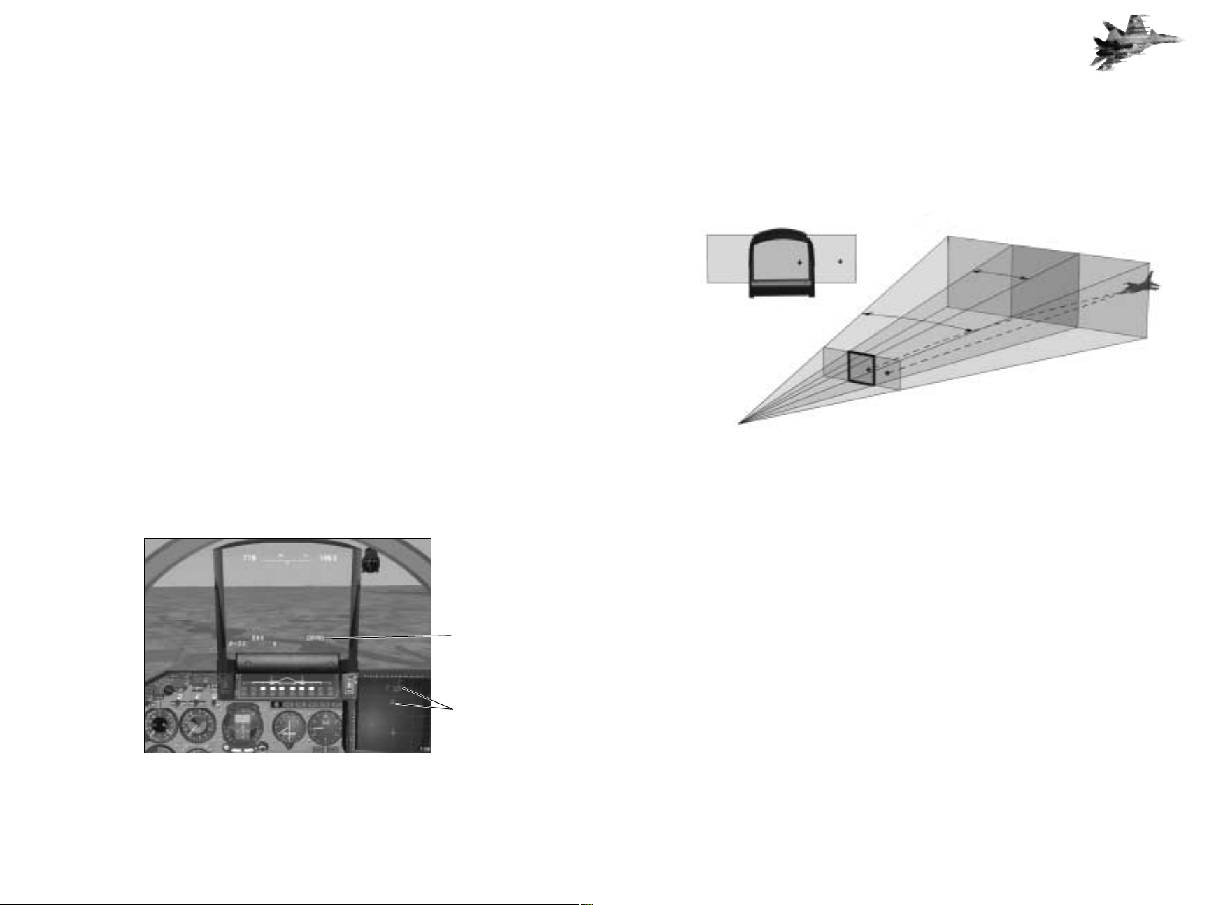
HUD Scaling Considerations
Keep in mind that the scan zone for sub modes is larger than the area covered by the HUD.
Targets are therefore “scaled” to fit the dimensions of the HUD. The target marker in the HUD,
consequently, points toward the target but is not an accurate indicator of the target’s azimuth and
elevation. The gimbal markers on the MFD will give you a better idea as to how close the gimbal
limit for the target is and you will easily interpret off boresight angle.
4-8b: Target Positions are Scaled to Fit the HUD
Acquiring A Target in LD< (BVR) Mode Step-by-Step
Let’s walk through the process of acquiring a BVR target.
Step 1. Switch to BVR Mode
Press the 2 key and check that the HUD Mode Indicator shows the notation of the LD< – J<P
(BVR - SCAN). If there is a friendly AWACS aircraft airborne J<P (SCAN) will be replaced by
LHKJ (AWACS). Use the + and – keys to adjust the range displayed on the MFD and the HUD.
If you have an AWACS datalink, then you will almost immediately receive contact data on the MFD:
Friend or foe, distance, and aspect angle. (See above for more on AWACS). If this is the case, you
can cycle through the contacts on your MFD by selecting the (~) key. Then go to step 5.
Step 2. Select a sensor.
Activate the radar or EOS. The notation at the left of the HUD should read B (I) or N (T) for the
radar and EOS, respectively. Alternatively, the HUD will display LHKJ (AWACS) if a friendly
AWACS aircraft is airborne and in range.
Step 3. Direct Scan Zone
Using the Shift - coolie hat on your joystick or the scan zone control keys, aim the scan cone in the
portion of airspace you wish to scan. The HUD will immediately show detected contacts, if any.
CHAPTER 4: Air-to-Air Combat 55
When tracking a target in Attack Mode, manoeuvre your aircraft so that the Aiming Reticle stays
close to the HUD centre datum. This eases your work load when the target is not very visible and
prevents the target from breaking the lock. Remember, if you use the EOS, the flashing of the Shoot
Cue with a frequency of 1 Hz warns you that the system is not measuring the range to the target.
Keep in mind that for SARH missiles, it is necessary to illuminate the target for the entire flight
time of the missile. After launch this will be represented by the A (Auto-track) cue flashing at 1
Mz. So know your missiles!
If the target leaves the tracking area, or you break the lock by pressing the Tab key, or the target is
destroyed, the radar (the EOS) returns to the submode which preceded the Auto-track. Similarly, if
the radar or EOS is damaged or you switch sensors off, the lock breaks and the radar returns to
the submode which proceeded the Auto-track.
LD< – LHKJ (AWACS) AWACS Datalink
The Flanker’s ability to datalink with AWACS aircraft allows pilots to locate, stalk, and engage targets without ever engaging onboard sensors. This form of “stealth” lets the Flanker close on its
prey without betraying its presence. A friendly AWACS aircraft (an A-50 or E-3) must be airborne
simultaneously to your aircraft. The datalink information can be viewed on the MFD in all combat
modes as well as the NAV modes, however, these contacts can only be selected for targeting
from the BVR mode, with the radar and the EOS off. While in BVR mode, if there is a friendly
AWACS aircraft airborne, a datalink will be established and contacts detected by the AWACS will
appear on the MFD as standard aircraft symbols (friendly and enemy). The AWACS contacts will
appear more subdued (less bright) than regular contacts. While in BVR mode you can use the ~
Key to cycle through AWACS contacts on the MFD. A selected contact will appear brighter. Use
the Tab Key to lock up a selected AWACS target in Auto-track. Once you hit the Tab Key your
radar will illuminate the target and you will no longer be passive.
4-8a3: LHKJ (AWACS) Submode
FLANKER 2.0
FLANKER 2.0
54 CHAPTER 4: Air-to-Air Combat
AWAC’s Datalink
Active
Contacts
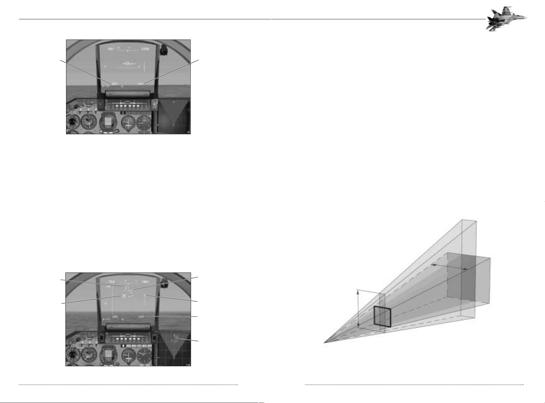
Step5. Lock onto the target
To lock onto the selected TWS contact, press the Tab Key. If the lock parameters are met (aspect
angle, Radar Cross Section, distance, speed, etc.), the radar (or the EOS) switches to Attack
Mode. The Autotrack Cue (A) appears above the Radar Cue or the EOS Cue.
To lock onto a target if you have an AWACS datalink, select the Tab key.
It is recommend that you lock onto a target at a range that is close to a reliable range of the
selected air-to-air missile. It gives the target less warning that it has been locked on and therefore
increases your probability of scoring a fast kill.
On the MFD the locked target will be illustrated by a solid triangle symbol, the target aircraft is
now being illuminated by a 2.5∞ radar beam.
Step 6. Select Air-to-Air Missile and Launch
Select the appropriate air-to-air missile for the range and type of target by pressing the D Key.
Consider range, manoeuvreability, size, and speed of the target. Once the target is within the
launch parameters of the weapon and the launch cue is displayed in the center of the HUD, your
are authorized to fire the weapon.
<D< /Close Air Combat Mode
The <D< (CAC) Close Air Combat mode is used for attacking targets which you have spotted
visually or which are known to be within close range (less than 25 km). The radar (the EOS) locks
onto a target in an area limited by the angular dimensions of the HUD, namely 20°x20° (±10° in
azimuth and ±10° in elevation). The IKTV (HMTD) submode permits the pilot to acquire targets with greater off boresight angles.
4-10c: The <D< Scan Cone
CHAPTER 4: Air-to-Air Combat 57
4-9: The J<P (SCAN) Submode Symbology
Step 4. Assigning Contacts to Track While Scan mode
To select a particular target, steer the HUD Target Designator Box (HTD Box) onto the contact of
interest and press the Tab key. The contact will switch from being scanned to tracked. This
method is called “manual selection” since you are selecting an individual contact to be tracked by
the radar. The Weapons Control System also offer an automatic contact analysis routine whereby
contacts with the highest closure speed/distance ration will become tracked contacts.
To automatically designate multiple scan contacts to the Track While Scan mode press the 2 key
when there are multiple scan contacts displayed on the HUD while you are in J<P (SCAN)
mode. Up to 8 of the scan contacts will now be designated as track contacts and will now be
displayed on the MFD.
To remove an individual contact from Track While Scan mode and place it back to scan, place the
HTD Box on the triangle symbol on the HUD and press the Ctrl-Tab Key. The contact will be
removed from the MFD and the triangle symbol will become a dash symbol on the HUD.
To remove all TWS contacts from the MFD and return to Scan mode press the 2 Key again and
restart the sequence.
4-8a2: The CYG (TWS) Submode Symbology
FLANKER 2.0
FLANKER 2.0
56 CHAPTER 4: Air-to-Air Combat
Track and Lock
Sub Mode Selected
BVR Mode Selected
Scanned Contacts
Range Bar
Tracked Contacts
Track While Scan Sub Mode
Tracked Contacts
Selected Contact
 Loading...