

Page 1

Chapter 11
Introduction to the Mission Editor
..........................................................................
175
Chapter 12
Planning Your Mission
..................................................................................................
185
Chapter 13
Building New Missions
................................................................................................
195
Chapter 14
Campaigns
..........................................................................................................................
209
Chapter 15
Multiplay
..............................................................................................................................
217
Chapter 16
Understanding SAMs and Countermeasures
..................................................
223
Russian Alphabet
............................................................................................................
247
Glossary
................................................................................................................................
248
Index
........................................................................................................................................
254
Table of Contents
Chapter 1
Introduction
......................................................................................................................
1
Chapter 2
Quick Start
..........................................................................................................................
5
Chapter 3
Cockpit
................................................................................................................................
27
Chapter 4
Avionics and Combat Systems
..................................................................................
39
Chapter 5
Ground School
..................................................................................................................
69
Chapter 6
Weapons
..............................................................................................................................
91
Chapter 7
Training
................................................................................................................................
127
Chapter 8
Emergency Procedures
................................................................................................
139
Chapter 9
Tactics
..................................................................................................................................
145
Chapter 10
Crimea
..................................................................................................................................
171
FLANKER 2.0
FLANKER 2.0
Table of Contents
Page 2
CHAPTER 1: Introduction 1
INTRODUCTION
Welcome to Flanker 2.0! This simulation is the result of a great amount of effort, by many people
from all over this planet. A development team in Russia, a publisher with staff located in the United
States and the United Kingdom, testers located in Canada, Scandinavia, Asia, the Balkans, all over
Europe, and just about every point in between. This has truly been an international effort. We thank
you for your purchase and hope that you enjoy this product as much as we enjoyed creating it.
FLANKER BRIEFING
The Su-27 Flanker and its descendants are some of the most impressive and capable aircraft in
the world. Born in the dying days of the cold war, the Flanker did not have an easy life and the initial design suffered from serious problems. The breakup of the Soviet Union and subsequent collapse of the Russian economy hindered its development, in many ways denying the Flanker an
opportunity to prove itself as the world’s greatest tactical aircraft.
History of the Flanker
The aircraft’s early history was so problematic that it faced outright cancellation on numerous
occasions. Conceived in 1967, both the Su-27 and MiG-31 were intended as long-ranged interceptors to replace the Tu-128, Su-15, and Yak-28P aircraft. More specifically, the design required
the Flanker to be capable of destroying enemy aircraft protecting enemy targets; a thinly disguised
directive to best the U.S.-built F-15 in air-to-air combat. The initial prototype, the T-10-1, conducted its maiden flight on May 20, 1977. Although photographed by Western intelligence satellites, no
clear pictures were available to the public until a TV documentary about the Sukhoi OKB (design
bureau) displayed still pictures of the Flanker in 1985. Given the basic blended body, twin tail fins,
and widely spaced engines, Western analysts inevitably pointed to the Su-27 as a copy of the
Western designs found in the F-16, F-15, and F-14. In truth, the similarities seem to be common
solutions to problems shared by Eastern and Western design requirements.
CHAPTER 1
Introduction
CHAPTER 1
Introduction
Defense Visual Information Center - Department of Defense
Page 3

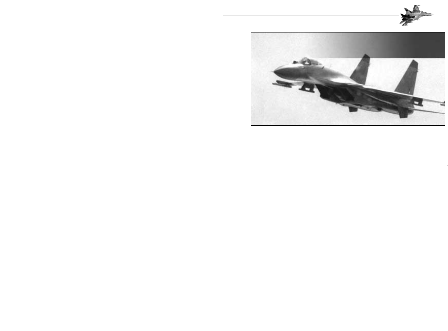
Su-33 – Originally designated the Su-27K, this variant is specifically designed for the demanding
role of carrier-based aviation. Equipped with canards for improved take off and landing performance, the first Su-27K made its maiden flight in 1985. The shortened tailcone, intended to
reduce risk of tail strike during high AOA landing, reduces the space for defensive equipment
(including chaff and flare dispensers). Whereas the Su-27 was tailored primarily as an air-to-air
interceptor, the Su-33 is a multi-role aircraft (a necessity of carrier based aviation operating far
from home bases). The Su-33 retains to a large extent the avionics and cockpit of the basic Su-27.
Su-34 – Also known as the Su-32FN, this aircraft is a two-seat (side by side cockpit), longrange, day/night fighter-bomber, intended to replace the MiG-27, Su-17, and Su-24. The Su-34
first flew on December 18, 1993. Canards improve manoeuvreability, and an elongated tailcone
reportedly houses aft facing missile guiding systems. The aircraft features an improved glass cockpit along with the traditional analog gauges. Besides having a unique ejection system and terrain
following radar, the aircraft actually has a toilet and sleeping facilities onboard.
Su-35 – Originally designated the Su-27M, this multi-role variant of the Su-27 features improved
avionics; a modern “glass cockpit” replacing the traditional analog gauges with multi-function displays and digital readouts. The collapse of the Soviet Union has hindered the deployment of the
Su-35, prototypes of which perform routinely at international airshows.
Su-37 – Having appeared at numerous airshows, this variant is basically an Su-35 equipped with
thrust vectoring engine exhausts for improved low-speed agility. Russia has stated that this will
eventually become the standard operating variant.
Ready For Action
This concludes our introduction to the Flanker family, arguably the most powerful and versatile
group of aircraft ever built. Chapter 2 will orient you with the simulation interface and explain how
to get airborne quickly.
CHAPTER 1: Flanker Briefing 3
The program, though, quickly began to experience problems. The second prototype, number T-102, suffered control system failure, and the pilot was killed during ejection. By 1979, additional prototypes were flying, but the program was failing to meet its performance requirements. Drag was
higher than expected, engine performance was low, fuel consumption was too high, and heavy
avionics in the nose decreased stability. Further, flutter problems required the addition of anti flutter weights in the tailfins, tailplanes, and wings. By this time, information about the F-15 indicated
the Flanker would be no match for the American jet in air-to-air combat. A redesign was needed.
Prototypes T-10-7 and T-10-8 were redesignated T-10S-1 and T-10S-2 and built to a substantially
improved design. An entirely new wing improved lift while offsetting the weight of the equipmentpacked nose. Anti-flutter weights, serving as wingtip missile launch rails, replaced the curved
wingtips of the early prototypes. The fuselage received substantial modifications, fins were
increased in size, and the airbrake was redesigned. The T-10S-1 first flew in 1981. Avionics problems continued to dog the program, though, and service deliveries didn’t begin until 1985, roughly
a decade after the F-15 entered service. One of the T-10S prototypes, redesignated as P-42, was
prepared to capture numerous aviation records from the F-15. Stripped of avionics and unnecessary gear, the P-42 was fitted with modified engines and set a total of 27 world records between
October 1986 and December 1988, including numerous time-to-height records.
Performance Characteristics
T-10-1 SU-27 SU-33 SU-34 SU-35
Powerplant
2 x AL-21F3 2 x AL-31F 2 x AL-35F 2 x AL35F 2 x AL-35F or AL-31MF
or AL-31MF or AL-31MF
Thrust Each Engine
11,220kg 12,522kg 14,029kg 14,029kg 14,029kg
Wingspan
14.8m 14.8m 14.8m 14.8m 15.1m
Height
5.92m 5.98m 5.95m 5.95m 6.42m
Max Takeoff Weight
25,786kg 30,000kg 30,000 kg. 44,400kg
Flanker Variants
Most legendary tactical aircraft share a common trait: versatility. The Flanker is no exception, with
numerous sub-variants arriving on the scene. Usually, aircraft variants are identified by adding a
letter to the base designation (F-16A, F-16B, F-16C, etc.), Sukhoi eventually abandoned this
method, giving each variant a new designation. Some speculate that this was intended to promote
the idea that each variant was a whole new aircraft, hopefully improving domestic funding as well
as overseas sales. Flanker operators include Belarus, Ukraine, Russia, India and China.
Su-30 – Initially called the Su-27PU, this is an improved version of the original Su-27UB two-seat
trainer. Unlike the Su-27UB, the Su-30 is a fully operational combat aircraft. It is optimized for missions lasting 10 or more hours, and would normally act as an airborne mission controller.
Su-30MK - This improved version of the Su-30 is optimized for delivery of precision-guided
munitions, some of which may have stand-off ranges of 120km (75 miles). The Su-30MK also features an improved navigation and weapons systems.
FLANKER 2.0
FLANKER 2.0
2 CHAPTER 1: Flanker Briefing
Page 4
CHAPTER 2: Quick Start 5
QUICK START
The main menu provides several options for becoming airborne. The three quickest ways to takeoff
are via the Instant Combat, Training, and Mission menu modes.
Installation
You must install Flanker 2.0 game files to your hard drive and have the Flanker 2.0 CD in your CDROM drive to play this game.
To install the game, insert the CD into the CD-ROM drive. When the pop-up window appears,
click on the Install option. If you have disabled the Windows Autorun, or if it does not function,
Explore the CD and double-click on the Setup icon. Follow all on-screen prompts to complete the
installation.
What Comes with this Game?
Your game box should contain this user manual, a pilot checklist and a Flanker 2.0 CD. This user
manual explains how to play and contains important information on menus, scenarios, and unit
classes and equipment.
System Requirements
To play Flanker 2.0, be sure your system meets the following system requirements:
• Pentium 200 MHz IBM PC or compatible
• 32 MB of RAM
• Windows® 95 or 98 - NOTE: This is a Windows 95 game and cannot be played on Windows®
NT systems. Multitasking is not recommended when playing Flanker 2.0
• An uncompressed hard drive with at least 600MB free
• 8 X CD-ROM drive or faster
• A DirectX compliant 3D accelerated video card with 4MB of memory and a Colour SVGA
Monitor
• A 100% Microsoft (or Logitech) compatible mouse
• Microsoft mouse driver version 9.00 or higher or Logitech mouse driver version 6.24 or higher
• 100% DirectX Compatible Sound Card
CHAPTER 2
Quick Start
CHAPTER 2
Quick Start
FLANKER 2.0
Defense Visual Information Center - Department of Defense
Page 5
Despite the differences in operating environments, as a Flanker pilot you will find very little
difference between the two aircraft. The cockpits, controls, and avionics are virtually identical. The
Su-33 is a little heavier than the Su-27. The Su-33 has more powerful engines, but this performance advantage is somewhat offset by increased fuel capacity (for longer range) and increased
maximum takeoff weight. Except for the rigors of carrier takeoffs and landings, you should have
little difficulty switching between the two aircraft.
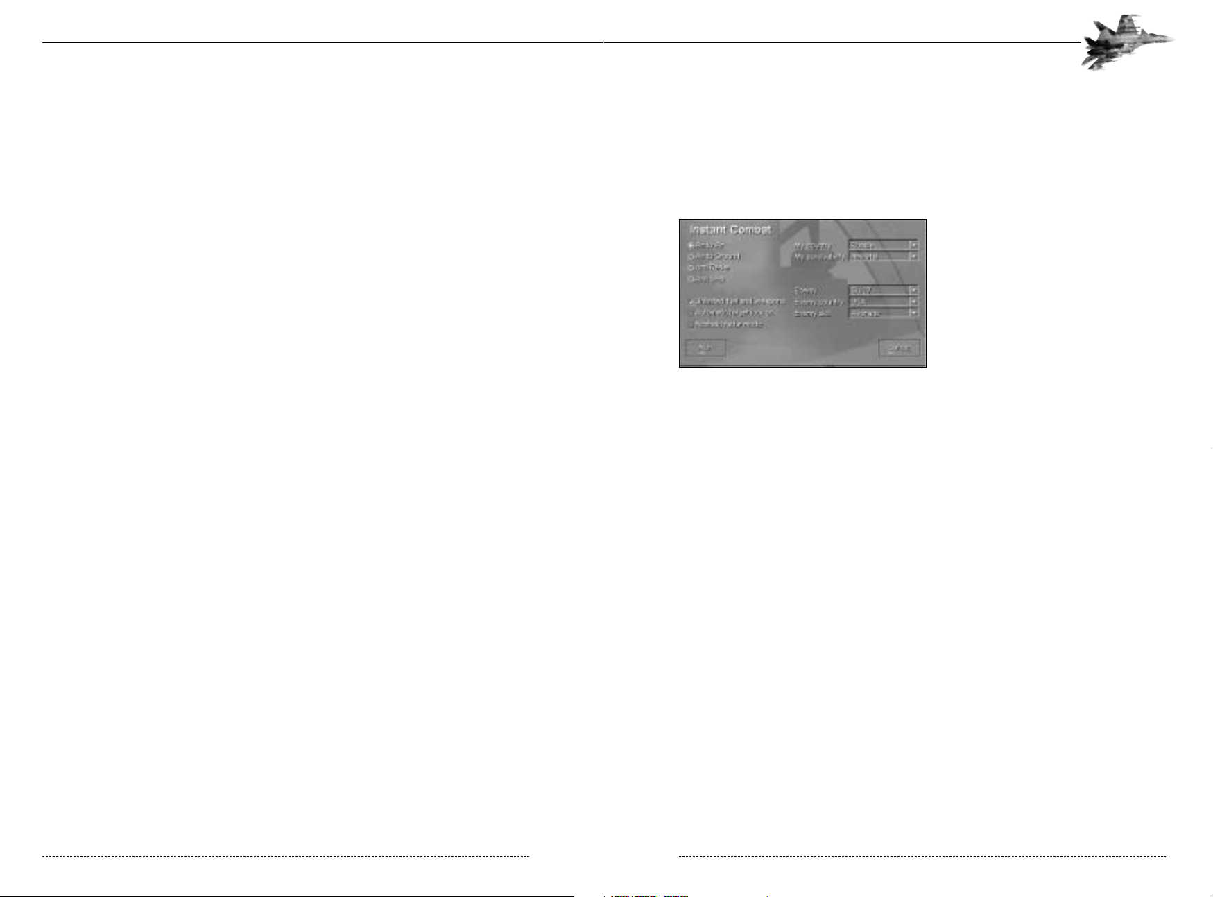
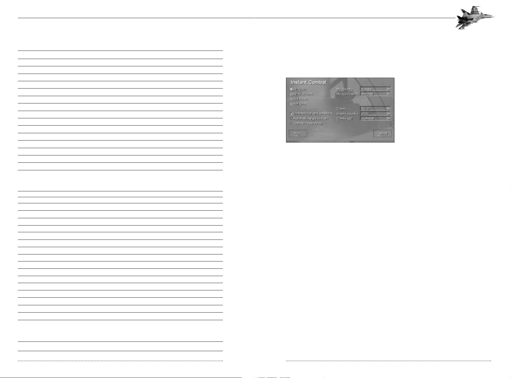
Instant Combat Mode
Instant Combat mode is the quickest way
to get airborne and take on an opponent.
It features a simplified radar and flight
model. From the main menu, select “Instant
Combat”, then select “Air-to-Air.” Check the
“unlimited fuel and weapons” and the
“automatic target lock-on” boxes. From the
pull-down menus, select “Russia” for my
country and “immortal” for my survivability.
For the enemy, select the type of aircraft you wish to fly against, select a country for it to fly for,
and specify the quality of the computer controlled pilot. When you’ve completed configuring the
scenario, select the “Run” button. You’ll be placed in a Flanker with an appropriate weapons load
out. The mission will generate a random number (1-6) of enemy targets. Manoeuvre toward your
target and engage!
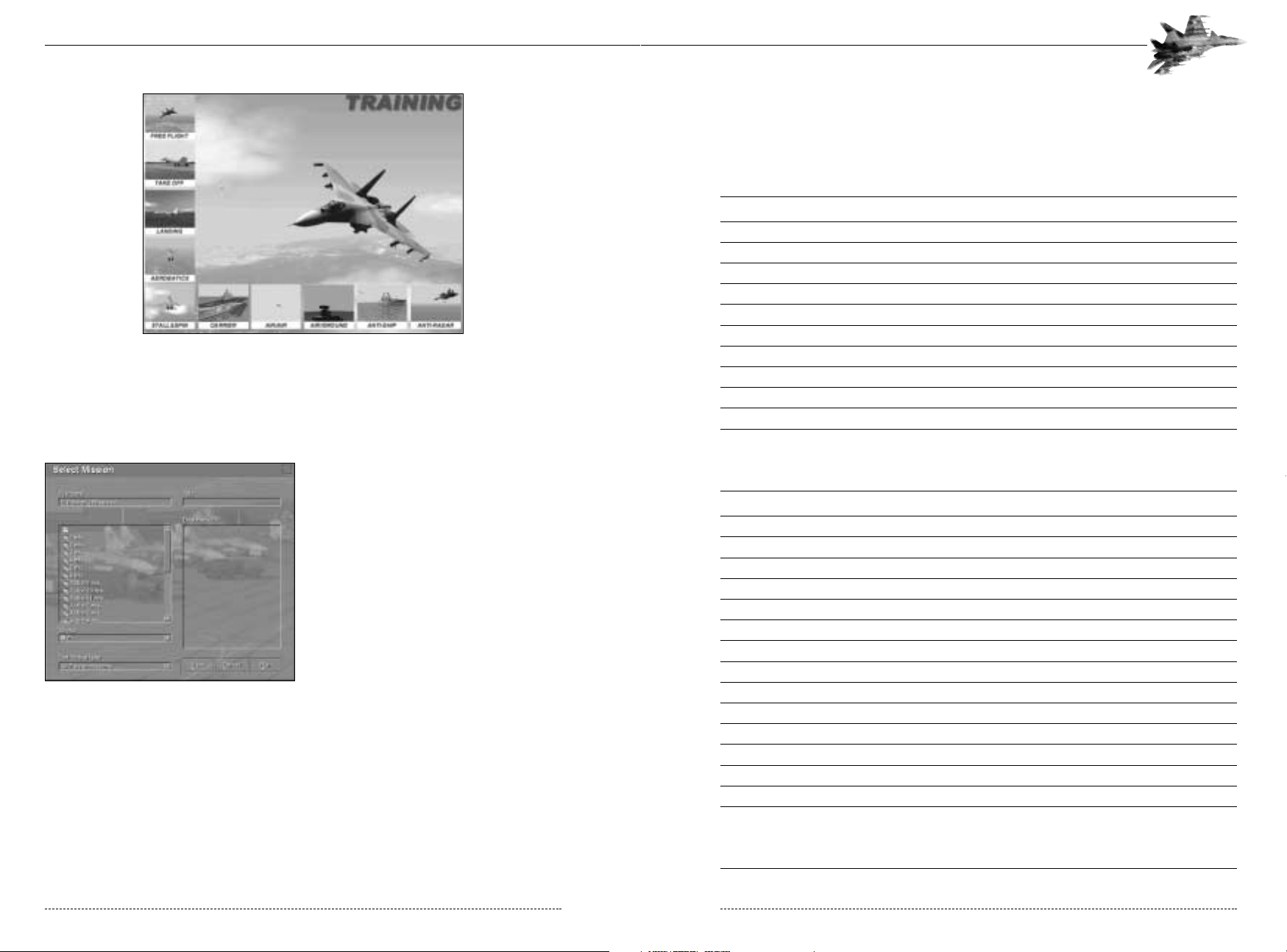
Training Mode
Training mode provides a series of pre-defined missions configured into ten categories. Each category may have several individual missions catering to specific training needs. Choose “Training”
from the main menu, the select the appropriate category (Free Flight, etc.) Next, select a specific
mission within that category group.
The pre-recorded training mission begins playing while the instructor pilot narrates. The instructor
will walk through the mission, explaining the procedure or task step-by-step. At anytime, you may
take control and complete the mission yourself by pressing the ESC key. We recommend allowing
the instructor to fully describe the task and complete the narration before taking manual control.
You may exit the mission by pressing the Ctrl-Q key.
CHAPTER 2: Overview 7
In addition to the basic system requirements, the game requires that DirectX 6.1 be installed to
your hard drive. The option to install DirectX 6.1 appears during the game installation. At the end
of installation, you are prompted to register Flanker 2.0 electronically. For network play, you need a
DirectPlay compatible network adapter.
Flanker 2.0 utilizes Microsoft DirectX sound and video drivers. DirectX is a programming tool created by Microsoft, and the installation of DirectX may cause video problems and system anomalies
with computers using video drivers that arenít DirectX compliant. DirectX is a Microsoft product,
and as such, this publisher cannot be responsible for changes that might occur to your computer
system due to its installation. For DirectX related problems that cannot be fixed by updating to
your video cardís latest Windows driver set, you must contact either Microsoft or the manufacturer
of your video card for further technical support or service.
Microsoft retains all intellectual property rights to DirectX. The user has been granted a limited
license to use DirectX with Microsoft operating system products.
Uninstalling the Game
To uninstall the game, select that option from the Autorun menu, or choose Settings from
the Windows 95 Start Button, and select Control Panel. In the Control Panel, select Add/Remove
Programs, left-click on Flanker 2.0,and click on the Add/Remove button. The game and all
of its components are then removed from your hard drive, except for your saved games or
edited scenarios.
OVERVIEW
We know you’re anxious to start flying, so this chapter is divided into two portions. The first portion describes how to get through the menus quickly, how to get airborne, and how to control the
aircraft. The second portion of this chapter explains each menu choice in more detail.
Su-27 vs Su-33
Flanker 2.0 lets you pilot either the Su-27 or Su-33. Your first question is probably, “What’s the difference?” The Su-33 is a navalized version of the basic Flanker; an aircraft designed to operate
from aircraft carriers. Whereas the Su-27 is a pure interceptor with no real secondary groundattack role, the nature of carrier-based aviation requires the Su-33 perform both ground-attack
and air-to-air duties. There may not a friendly airbase from which supporting Su-25’s can launch
and recover. The carrier’s Su-33s will have to perform both roles.
FLANKER 2.0
FLANKER 2.0
6 CHAPTER 2: Overview
2-1: The Four Forces of Flight
Page 6
Key Commands
Now that you’re in the cockpit you need to know the basic controls. The following table shows the
key commands necessary to control the simulation.
PROGRAM CONTROL
KEY ACTION
Ctrl-A
Accelerate program speed by 2 times.
Ctrl-Q
Quit program from Main Menu, also ends mission
Alt-X
Quit Mission Editor and return to Main Menu
Ctrl-S
Toggle Sound On or Off
Ctrl-T
Cancel Trim Settings
Shift-M
Reset Audible Warnings
S
Toggle Pause/Resume normal speed
Esc
Allows user to take control of aircraft while viewing a track file playback
0
(zero) [not Key Pad 0] Turns on microphone for recording mission playback
Ctrl-L
Starts network play game from Mission Editor
Ctrl-M
Chat feature for multi-player network games
FLIGHT CONTROL
KEY ACTION
Down Arrow
Nose up (without joystick)
Up Arrow
Nose down (without joystick)
Left Arrow
Bank left (without joystick)
Right Arrow
Bank right (without joystick)
Ctrl-.
(Period) Trim up
Ctrl-;
(Semi-colon) Trim down
Ctrl-,
(Comma) Trim left
Ctrl-/
(Slash) Trim right
Z
Rudder left (in flight), left turn (taxi)
X
Rudder right (in flight), right turn (taxi)
Ctrl-Z
Trim left rudder
Ctrl-X
Trim right rudder
H
Toggle altitude stabilization mode
J
Toggle auto-throttle
K
Execute “Pugachev’s Cobra”
CHAPTER 2: Overview 9
2-3: The Training Mission Screen
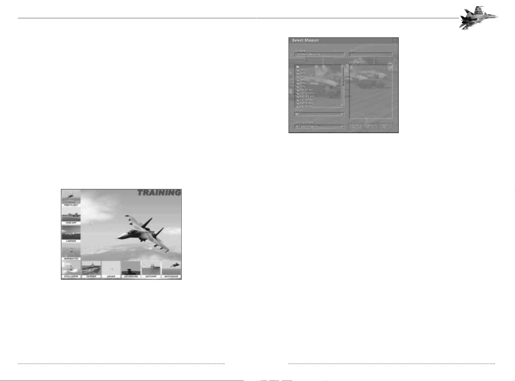
Missions Mode
From this menu you can review and load all
saved missions available in the game, including pre-defined missions that come with the
simulator as well as those you’ve added.
You can use the mission mode to begin a
campaign or simply fly an individual sortie.
Simply click on the desired mission and
click the Run button.
2-2: The Mission Mode Select Screen
FLANKER 2.0
FLANKER 2.0
8 CHAPTER 2: Overview
Page 7

KEY ACTION
6
Select Longitudinal Missile Aiming (LNGT/FIO) mode
7
Select Air-to-ground (GND/ZEMLYA) mode
`
Cycle through targets on MFD in AWACS and Ground Attack Modes
Tab
Place designated contact in Track While Scan from Scan
Ctrl-Tab
Remove tracked contact from Track While Scan
Tab
Lock tracked target to Attack Mode
Tab
Lock/unlock target to Attack Mode in CAC submodes
Ctrl-H
Cycle through Heads Up Display (HUD) intensities
WEAPONS
KEY ACTION
D
Cycle through weapons selection
C
Toggle cannon
Q
Dispense chaff & flare
Shift-Q
Continuously dispense chaff & flares (Note: until supply is exhausted)
Spacebar
Fire current weapon
Ctrl+W
Jettison weapons in pairs while airborne, reloads weapons while on the ground
RADAR & ELECTRO-OPTICAL SYSTEMS
KEY ACTION
I
Toggle radar illumination on or off
O
Toggle Electo-Optical System (EOS) or weapon TV seeker on or off
Ctrl-I
Center radar antenna/Infra-Red Scan and Track(ISRT) ball
-
(Minus) Multi-Functional Display (MFD) zoom in
+
(Plus) Multi-Functional Display zoom out
Ctrl-V
Toggle Salvo mode on or off
BEYOND VISUAL RANGE MODE
KEY ACTION
Shift-;
(Semicolon) Move radar/EOS scan zone DOWN while in BVR
Shift-,
(Comma) Move radar/EOS scan zone LEFT while in BVR
Shift-.
(Period) Move radar/EOS scan zone UP while in BVR
Shift-/
(Slash) Move radar/EOS scan zone RIGHT while in BVR
;
(Semicolon) Move HUD target designator Box DOWN (BVR only)
,
(Comma) Move HUD target designator Box LEFT (BVR only)
.
(Period) Move HUD target designator Box UP (BVR only)
/
(Slash) Move HUD target designator Box RIGHT (BVR only)
CHAPTER 2: Overview 11
THROTTLE CONTROL
KEY ACTION
Page Up
Increase Throttle in increments (without throttle option enabled )
Page Down
Decrease Throttle in increments (without throttle option enabled )
Key Pad +
(Plus) Increase Throttle smoothly (without throttle option enabled )
Key Pad -
(Minus) Decrease Throttle smoothly (without throttle option enabled )
MECHANICAL SYSTEMS CONTROL
KEY ACTION
B
Toggle airbrake
Shift-B
Airbrake out
Ctrl-B
Airbrake in
Ctrl-E,E,E
Eject (Note: hold down Ctrl key and hit E three times)
E
Toggle active jamming (requires ECM pods in loadout)
F
Toggle flaps up/down
Shift-F
Flaps down
Ctrl-F
Flaps up
G
Toggle landing gear up/down
Ctrl-G
Toggle arrestor hook down or up (Note: Su-33 only, not Su-27)
P
Release drogue chute (Note: Su-27 only, not Su-33)
Ctrl-P
Toggle folding wings (Note: Su-33 only, not Su-27)
L
Dump fuel (in flight) or refuel (ground) (Note: Hold down key)
W
Engage wheel brakes (ground) (Note: Hold down key)
T
Toggle wingtip smoke
Shift-M
Reset Current Audible Warning
NAVIGATION
KEY ACTION
`
Select next waypoint or airfield
A
Toggle autopilot
1
Toggle to set Navigation (NAV) submodes
COMBAT MODES
2
Toggle to set Beyond Visual Range (BVR/DVB) submodes
3
Select Close Air Combat – Vertical Scan (CAC/BVB – VS) submode
4
Select Close Air Combat – Bore (CAC/BVB – BORE/STR) submode
5 Select Close Air Combat – Helmet-Mounted Target Designator
(CAC/BVB – HMTD/SHLEM) mode
FLANKER 2.0
FLANKER 2.0
10 CHAPTER 2: Overview
Page 8

KEY ACTION
Shift-F8
Target View – Your Aircraft to Target
F9
Ship View
Alt-F9
Landing Signal Officer (LSO) View
F10
Theater View
F11
Tower & Terrain View
Ctrl-Key Pad 5
Returns to Tower & Terrain View starting point or ends Padlock View
F12
Static Objects View
VIEW MODIFIERS
KEY ACTION
Ctrl-Home
Places external views to Friendly only
Ctrl-End
Places external views to Enemy only
Ctrl-Delete
Places external views to All
Ctrl-Insert
Places external views to Unknown (non-aligned) only
Key Pad Delete
Toggle Padlock View (Note: for Alt-F9 LSO View & F11 Tower View only)
Ctrl-Key Pad + (plus)
Switch to Weapons Release and Track View for F2 External, F4 Chase, F7 Active Ground Targets,
and F9 Ship Views only
Y
External View Information Display Toggle
COCKPIT VIEW CONTROL
KEY ACTION
Key Pad 1
Move head down and left
Key Pad 2
Move head down
Key Pad 3
Move head down and right
Key Pad 4
Move head left
Key Pad 5
Front View
Key Pad 6
Move head right
Key Pad 7
Move head up and left
Key Pad 8
Move head up
Key Pad 9
Move head up and right
Key Pad *
(Asterisk) Toggle Padlock View (Note: Must be in Cockpit View and in visual range)
M
Move head to view right mirror
N
Move head to view left mirror
CHAPTER 2: Overview 13
CLOSE AIR COMBAT MODE
KEY ACTION
;
(Semicolon) Move radar/EOS scan zone DOWN while in BVR
,
(Comma) Move radar/EOS scan zone LEFT while in BVR
.
(Period) Move radar/EOS scan zone UP while in BVR
/
(Slash) Move radar/EOS scan zone RIGHT while in BVR
GROUND MODE
KEY ACTION
;
(Semicolon) Move radar/TV seeker scan zone UP
,
(Comma) Move radar/ TV seeker scan zone LEFT
.
(Period) Move radar/ TV seeker scan zone DOWN
/
(Slash) Move radar/ TV seeker scan zone RIGHT
WINGMAN COMMANDS
KEY ACTION
End
Dispatch wingman on mission & allow him to return to base afterwards
Del
Dispatch wingman on mission. On mission completion, join up
Home
Join up in formation
Ins
Toggle tight formation or loose formation
[
Attack my target
]
Cover my six o’clock (rear) position
VIEW SELECTION
KEY ACTION
F1
Cockpit View
Ctrl-F1
Natural Head Movement View
Key Pad *
(Asterisk) Padlock View (Note: Must be in Cockpit View and in visual range)
F2
External View – All Aircraft
F3
Fly-By View
F4
Chase View
F5
Air Combat View
F6
Weapons View
F7
Active Ground Objects View
F8
Target View
Ctrl-F8
Target View – Target to Your Aircraft
FLANKER 2.0
FLANKER 2.0
12 CHAPTER 2: Overview
Page 9
THE MAIN MENU
The main Flanker 2.0 menu provides access to five modes of play, an options screen and a
reference encyclopedia. This section describes each of these items.
Instant Combat
The Instant Combat mode provides a
quick way to fly an Su-27 or Su-33
against hostile forces. First select the
type of mission, air-to-air, air-to-ground,
anti-radar or anti-ship. As the names
imply, the mission types determine the
types of targets available during the
mission. Select anti-radar, for example,
to practice targeting various radar systems. Select anti-ship to practice
attacking different ships.
2-4: The Instant Combat Mode Setup Screen
Next, configure your aircraft. The “My Country” pull down menu specifies which country you’re
flying for. “My Survivability” indicates how resistant your aircraft is to damage. Configure who and
what you want to fly against in the mission and then select Run.
To exit a mission, simply select the Ctrl+Q key.
My country
You may choose to fly a Su-27 for Russia, the Ukraine, Turkey, the USA or Unknown.
My survivability
• Immortal: You cannot be killed. Your aircraft takes not damage and your aircraft will “bounce”
off the ground.
• Good: Your aircraft can be killed 3 times and then it will take damage normally.
• Realistic: Your aircraft will take damage normally.
Enemy
Depending upon the type of mission you select, this box will allow you to fight against all of the
types of opponents available in the game.
Enemy country
You can choose to fight against Russia, the Ukraine, Turkey, the USA or Unknown. This choice
does not limit what types of opponents you can select.
Enemy skill
You can select Average, Good, High, Excellent and Random.
Instant Combat Options
• Unlimited fuel and Weapons: This option gives you an unlimited amount of ordnance and fuel
to fight with.
CHAPTER 2: The Main Menu 15
EXTERNAL VIEW CONTROL
KEY ACTION
Key Pad 1 Move viewpoint down and left
Key Pad 2
Move viewpoint down
Key Pad 3
Move viewpoint down and right
Key Pad 4
Move viewpoint left
Key Pad 5
Centers view (Stops moving camera in F11 Tower & Terrain View)
Ctrl-Key Pad 5
Returns to starting point (F11Tower & Terrain View only)
Key Pad 6
Move viewpoint right
Key Pad 7
Move head up and left
Key Pad 8
Move viewpoint up
Key Pad 9
Move head up and right
Key Pad *
(Asterisk) Zoom in
Key Pad / (Slash) Zoom out
Key Pad 0
Jump to head-down cockpit view and back (Note: Hold down then release)
Alt-Key Pad *
(Asterisk) Starts moving camera forward (F11Tower & Terrain View only)
Alt-Key Pad / (Slash) Starts moving camera backward (F11Tower & Terrain View only)
Shift-(all view keys)
Moves viewpoints at a faster rate (Note: Hold down Shift and key)
MISSION EDITOR -
Hold down Ctrl to select multiple objects
KEY ACTION
FILE
Ctrl-N
Create new mission file
Ctrl-O
Open mission file
Ctrl-A
Save mission file
Alt-X
Exit Mission Editor and return to Main Menu
EDIT
Ctrl-Z
Undo last action
Ctrl-Y
Redo last action (cancel previous Undo)
Del
Delete selected object
VIEW
Ctrl-H
Hide objects
Ctrl-1
Crimean view
FLIGHT
Ctrl-B
Display Briefing
Ctrl-F
Start Mission
Ctrl-L
Network Play
Ctrl-M
Chat in Network Play
Ctrl-R
Record Track File
CAMPAIGN
KEY ACTION
Alt-Z
Remove objects from Condition
FLANKER 2.0
FLANKER 2.0
14 CHAPTER 2: Overview
Page 10
After you select the mission button on
the main screen, you will see the
Mission selection screen. The missions
are divided into directories, by mission
type. When you select a mission, the
mission briefing will appear in the
Description area on the right side of the
menu. As you will notice, you can
search for saved and previously built
missions from almost any location by
using the drive (if you have multiple drives or you are connected to a network).
Once you have selected a mission,
press the Run to button to go straight
into the mission. Select the View key to
view the mission within the Editor.
File Naming Convention
All of the playable files in Flanker have a naming convention which will automatically be created
when you save that file. You can search for files by type, by using the “List files of type” box on
the Select Mission menu. They file types are:
• Flanker Missions: *.mis
• Demo missions (tracks): *.trk
• Saved Missions: *.sav
• Debriefings: *.stt
Some basics about viewing your mission in the Editor:
• Your flight is shown in white. If you select it, you will see an Airgroup planning menu appear,
with all of the information about your flight. This information includes:
• Aircraft mission
• Payload
• Fuel
• Route with waypoint altitudes, speeds, tasks, estimated times and targets.
• Other flights and vehicles are shown in the colour of their nation. Selecting them will bring up a
menu showing their information.
• Selecting Met report from the Options (Alt+O) pull down menu in the Editor will allow you to
view the mission’s weather conditions.
• Selecting Skills from the Options (Alt+O) pull down menu in the Editor will allow you to view the
mission’s Skills settings
• Selecting the Edit (Alt+E) pull down menu in the Editor will allow you to see if the mission is
Classified. If the Classify selection is unavailable, then the mission is classified. This means that
you can look at the information in the mission, but you cannot change it.
• If you select to play a saved mission (*.sav) or a track (*.trk), you will also not be able to change
anything when you view it in the Editor.
CHAPTER 2: The Main Menu 17
• Automatic target lock on: This option means that when the mission starts with your radar locked
onto an enemy target.
• Realistic radar mode: In Instant Combat, the radar is defaulted to a simplified mode. You simply
manoeuvre your aircraft in the direction of the enemy and select the TAB key (assuming you do
not have the automatic target lock on option selected) to lock onto the target. To select another
target, use the (~) key to cycle through the targets.
If you select the Realistic radar mode, then you can select and use the real radar. The radar starts
off the mission in the simplified mode and then you can change to realistic ones as you play. For
more information on realistic radar, see Chapter 4. If you do not select this option, then your radar
will be locked into the simplified mode for the entire mission.
Next, configure your enemy aircraft. Select the type of aircraft you wish to fly against, which
country it flies for, and the quality of the computer controlled pilot.
Training
The training mode contains a series of customized, talking training missions focusing on specific
pilot procedures. The missions have been pre-recorded so you may either watch the procedure
performed by an experienced instructor pilot, or practice it yourself. The instructor will speak while
the mission plays, describing the situation and what you should be doing. The instructor will prompt
you to take control of the aircraft at your convenience by pressing the Esc Key or you can restart
the mission and take control at the beginning. To exit the mission, select the Control+Q key.
2-3: The Training Mission Screen>>
The individual training missions are described in Chapter 7.
Missions
Mission Mode provides direct access to all missions installed on your computer, including those
that ship with the game as well as ones you create or install later. This mode lets you view all missions, read their descriptions, and launch them without opening the mission editor.
FLANKER 2.0
FLANKER 2.0
16 CHAPTER 2: The Main Menu
Page 11
Options
Flanker 2.0 is designed for a wide range of computers. You
need to be away of the specifications of your computer and
what options will effect the performance while you play the
game. If you are playing an air to air mission, you might be
less concerned with the ground textures or the greenery
density, so you would turn these down to increase the
game’s performance.
Also, it is very important that you optimize your computer to get
the best performance. See the troubleshooting and recommended options sections at the end of this chapter and the
readme for more information on this.
2-8: The Options Screen
Graphics
The graphics section of the Options menu allows you to set your screen resolution and the major
items that effect your overall game graphics.
• Resoultion: Flanker 2.0 supports three resolutions: 640x480, 800x600, and 1024x768. Higher
resolutions look better, but require more CPU horsepower. Lower resolutions may not appear as
sharp, but will provide smoother frame rates on slower machines. Checking the “full screen” box
ensures the program runs in full screen mode instead of in a window and may help your game’s
performance.
• Texture Noise: An effect that adds raised, 3D textures to a texture map. An example might be
rivet on the side of an aircraft. This adds realism, but decreases performance.
• No Textures: This will turn off all of the 3D textures in the game. If the option is selected, ground,
objects, map, etc. are solid. You may also disable the editor textures (found in the Miscellaneous
section of the Options menu) when this is selected. This will option will greatly speed your
game’s performance, but also reduce all visual effects.
• Mipmapping: Specifies the use of textures. If the option is selected, several textures are used for
image of one object at various distances. If the option is unselected, only one texture is used. In
this case the distortions are greater. This option decreases performance.
• Primary display adapter: This allows you to choose to play the game using your primary or (if you
have on) a secondary card. Most people will have this box checked.
• 32 bit: This allows you to play the game in 32 bit colour. Be sure that your video card supports a
32 bit colour setting,
CHAPTER 2: The Main Menu 19
• Not all items in the mission may be viewed. In some cases the person who made the mission
may have Hidden units to add an element of surprise.
• Once you are done looking at your mission, select the Start mission button (Ctrl+F) or to record
the mission as a track (Ctrl+R).
• For more detailed information, see Chapter 10 on the Editor.
Campaign
Flanker 2.0 comes with a campaign consisting of a series of branching, inter-linked phases. By
using the campaign tools in the mission editor to create new campaigns, the number of possible
campaigns are limitless.
When you select the Campaign button on the Main Menu, the Select mission menu will be opened
to the campaign directory. Campaigns have the same file names as regular missions (*.mis).
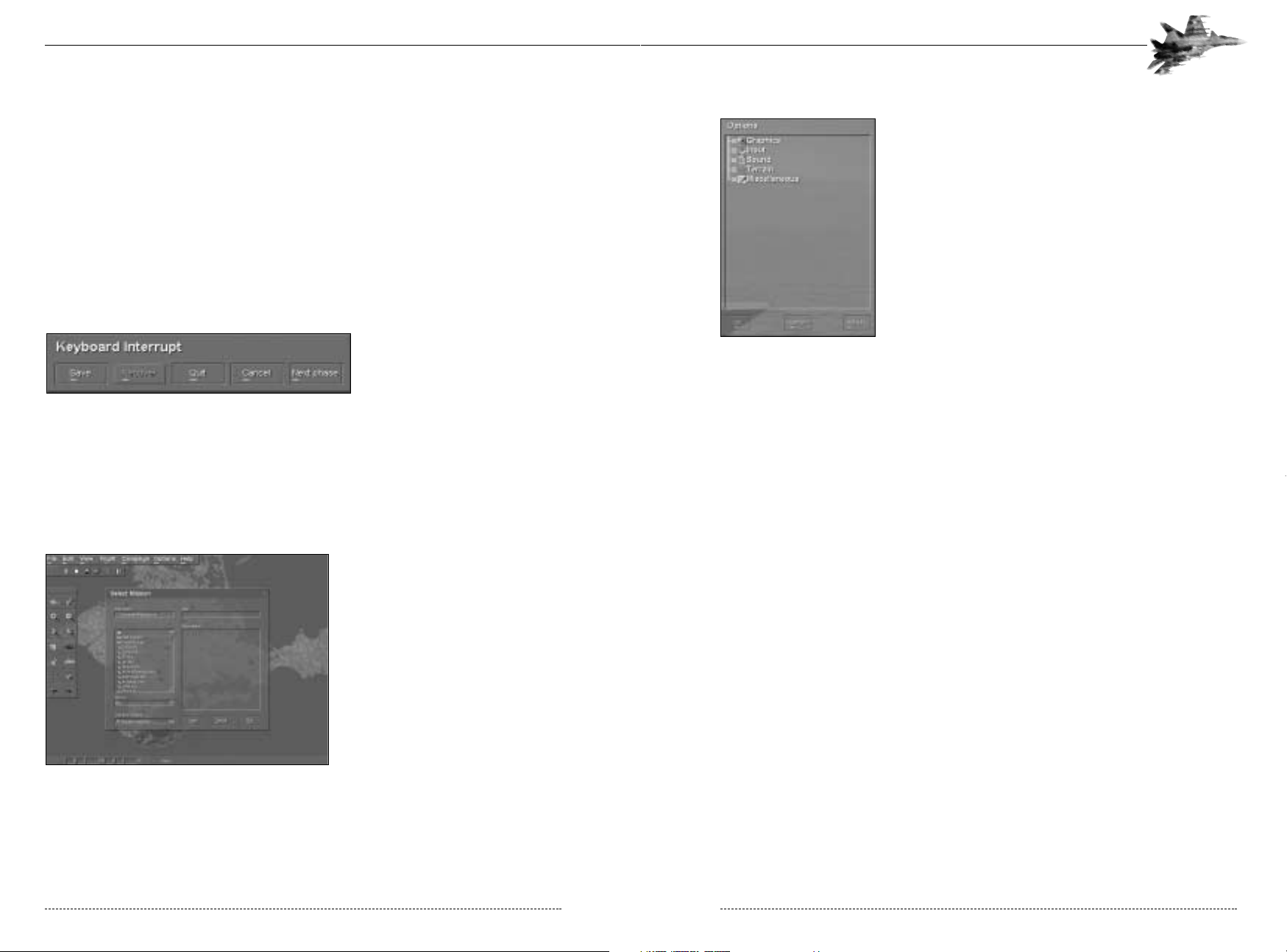
2-12: Next Phase Button
Campaigns initially play just like missions. At the end of the first phase in a campaign (select the
Ctrl+Q key to end the phase), you will get an option to go onto the next phase. When you select
that button, you will be taken to following phase of the campaign, if there is one and if you met the
conditions to do so.
Editor
Flanker 2.0 includes a powerful mission
editor, letting you create an infinite number of scenarios and campaigns that
can then be traded with your fellow
Flanker 2.0 pilots. Missions may be
“classified” or locked to prevent others
from editing them and viewing their
contents before flying. By ensuring that
the “surprise factor” is maintained, classified missions provide a stable base for
player-run competitions.
2-7: The Mission Editor
The mission editor is fully explained in Chapter 11.
FLANKER 2.0
FLANKER 2.0
18 CHAPTER 2: The Main Menu
Page 12
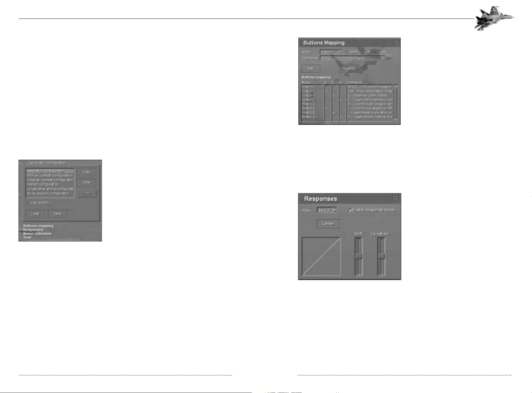
The Button Mapping menu shows all of the
buttons on your controller and the functions
that they have been assigned. The S, C, and
A columns signify if a Shift, Control, or Alt button needs to be depressed when this button
is pushed to perform this action. To remove
an action, highlight the desired button in the
window and then press the Remove button.
To add a button action, select the button you
want to add in the Button box at the top of
the menu, select whether you want to have
the Shift, Ctrl or Alt key depressed and then
select the action in the Command box. After
you have the action set the way you want it,
press the Add button. Once you have the
setup for that configuration the way you want
it, then close the Button Mapping menu and move onto the next configuration mode that you wish
to change. After you are done, press the Save button and save your new setup.
If you want to clear all actions from a configuration mode and start fresh, select the highlight the
configuration mode and then press the Clear key. This will wipe out all of your button actions for
that configuration mode. If you want to copy a configuration mode, select the configuration mode,
press the Copy key, select the new configuration mode and then press the Paste Key.
Selecting Responses brings up the
Responses menu and allows you to change
the shift and curvature on the X, Y, Z and R
axis for your controller in each of the configuration modes. Select the Enable Response
Curve box and then adjust the shift and curvature as desired. If you want to re-center it,
select the Center key. This means that if you
want a more responsive controller when your
aircraft is in the Close Air Combat mode than
in the Navigation mode, you can make that
change here.
2-15: Responses Menu
CHAPTER 2: The Main Menu 21
Input
The input menu lets you select what devices you have connected to your computer: joystick,
thrust controller, secondary thrust controller (for dual throttle control), and/or rudder pedals.
Joystick: Select this option if you are using a joystick. If you do select this option, then the keyboard commands for your basic flight options (right, left, up, down arrows, etc.) will not function.
Always insure that your joystick is calibrated and tested in Windows before you start Flanker 2.0.
Use joystick configuration:
This feature allows you to customize the configuration of your joystick within Flanker 2.0. This is a
very powerful feature which not only allows you to select what your controller does, but also what
it does when a certain combat mode is being used in a mission. Example: You may want button
1 on your joystick to select your next waypoint while your aircraft is flying in the navigation mode.
But when you select the Close Air Combat mode, you want that button to cycle through the onboard weapons. This can all be done using the joystick configuration.
To have the setup switch between configurations within the game, ensure that the Auto Switch
box is checked.
To load a pre-made setup, select the Load button on
Joystick Configuration menu. You will then get a
menu that lists a number of specific and generic controllers. Select the one that best fits your controller
and select the Load button. Your controller will now
use that setup. To view what action each button does
in each configuration mode, select the configuration
mode on the Joystick Configuration menu (Example:
Navigation, BVR, etc.) and then select Button
Mapping. This will bring up the Button Mapping
menu. All of the configurations modes (Navigation,
BVR, Close Air Combat, etc.) for the pre-made set-ups
are the same. Customize them to fit your likes.
2-13: Joystick Configuration
To have the setup switch between configurations within the game, ensure that the Auto Switch
box is checked.
FLANKER 2.0
FLANKER 2.0
20 CHAPTER 2: The Main Menu
Caption 2-14: Button Mapping Menu
Page 13
• Volume: Overall volume.
• Voice: Voices (Nagging Nadia, Instructor, Wingmen, etc.).
• Sound: Sound effects.
• Music: Music (Which only occurs while a mission is not progress).
• Recording: Your recordings within the game.
• Polyphony: Multiple sounds occurring at once.
Below the Sounds Level menu, there is a box to select your sound card driver.
Terrain
The terrain options menu lets you configure the visual quality and detail of the terrain and ground
objects, allowing you to customize performance for your computer and video card. You can adjust
detail levels for Textures, Objects, Greenery, and Roads/Rivers along with setting visibility ranges.
Higher/Farther settings will improve the graphics presentation, but reduce frame rate.
Lower/Nearer settings will decrease graphics quality, but will improve frame rate.
Misc
The miscellaneous options control how the program appears during play. Most of these options
configure the graphics and directly impact frame rate during game play. Users with slower
machines near the lower end of the recommended specifications may need to disable some of
these features to improve frame rate.
• HUD in Russian: If this is not selected, the HUD will be in English.
• G-Effects: When selected, you will see blackout and redout effects.
• Cockpit Mirrors: Enables/disables the mirrors position on the canopy rails.
• Cockpit Reflection: Enables a reflection on your canopy.
• Shadows: Enables aircraft shadows.
• Non-transparent Dialog Boxes: Toggles on opaque menus and dialogue boxes.
• Disable Editor Textures: Can only be selected if the “No Textures” option has been selected.
Turns off all textures in the Editor.
• Disable Buttons Animation: Enables/Disables all button animations in the game.
CHAPTER 2: The Main Menu 23
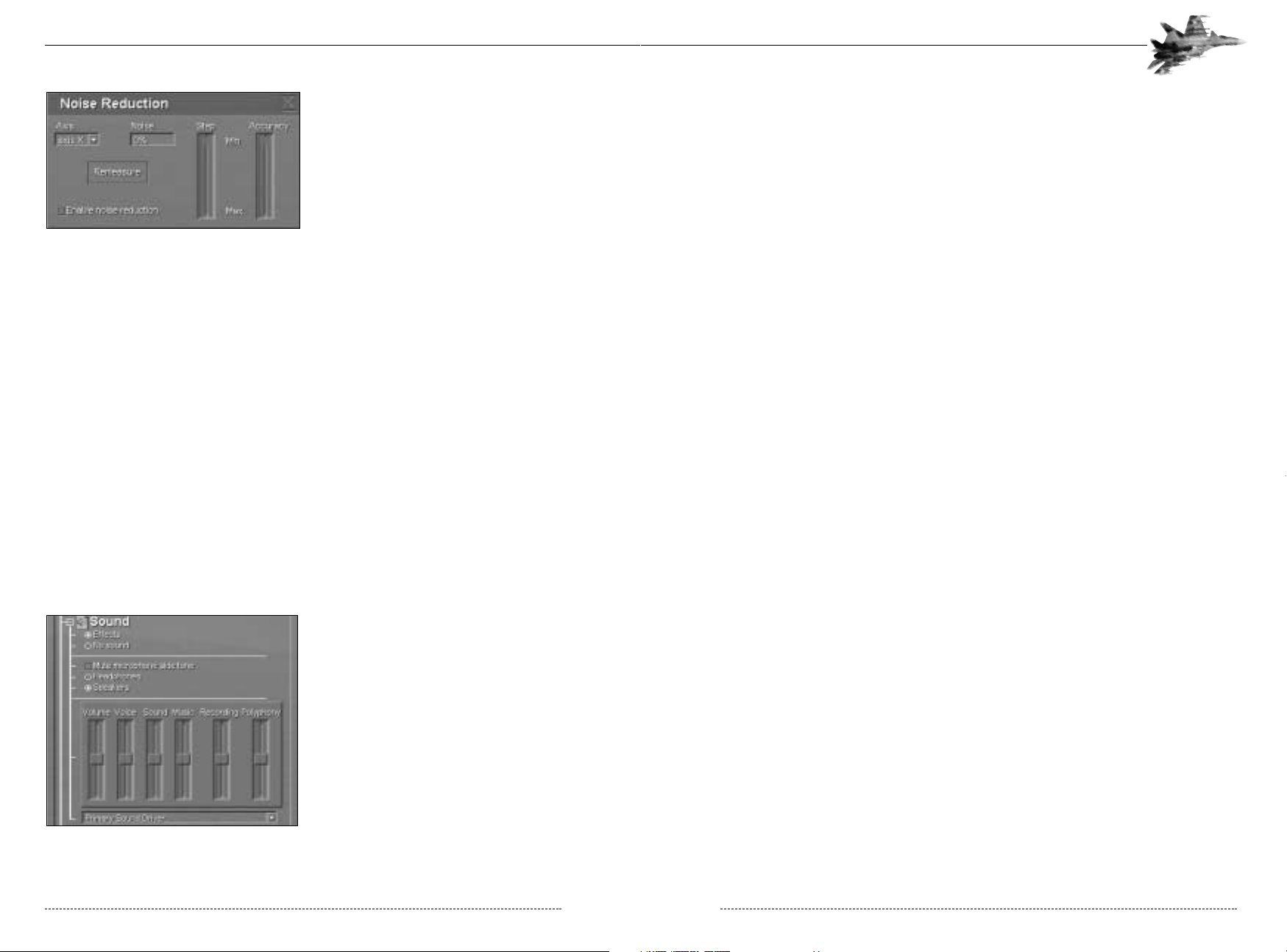
Selecting Noise Reduction brings up the
Noise Reduction menu and allows you to
change the Step and Accuracy on the X, Y,
Z and R axis for your controller in each of
the configuration modes. Select the Enable
Noise Reduction box and then adjust the
Step and Accuracy as desired. Move the
controller to measure the noise. If you want
to re-measure it, select the Re-measure key.
2-16: Noise Reduction Menu
Selecting Test allows you to see the range of motion on your controller, thrust and rudder pedals.
It also enables you to view the actions that buttons are set to when pressed.
Checking the Thrust, Second Thrust and Rudder Pedals allows you to use these controllers in
the game.
Sound
There are a variety of sounds in Flanker 2.0 that add to the overall experience and allow you to
immerse yourself more in the game. There are some important warnings and ambient sounds that
occur within the game (like an incoming missile warning). You will be at a serious disadvantage if
you are not able to hear them. You may also record your voice during missions (if you are using a
microphone). All of these options are set here.
• Effects/No Sounds: This turns all sounds on/off in the game.
• Mute microphone: The game will not record any sound coming from your microphone if this
is selected.
• Headphones/Speakers: Select the option you are using for better sound.
The Sound Levels menu found in the Options
menu, allows you to adjust the various audio
effects within the game.
2-17: Sound Levels Menu
FLANKER 2.0
FLANKER 2.0
22 CHAPTER 2: The Main Menu
Page 14
• Have no other programs running while playing the game. You may want to even disable some
applications that begin at startup. See the readme for more details.
• Ensure that you have at least 250MB of free hard drive space on your primary hard drive for
swap file space.
• Select the Options settings in the game that best fit your computer.
• In playing a 3D game, realize that the bigger the mission and the more objects that are in that
mission, the slower your performance will be. If you find that your performance is still slow after
optimizing your computer, then try running smaller missions.
Recommended Options Settings
Below are some recommended settings for various computer specifications. These selections
seem to be a good balance between game play and performance. Your mileage may vary.
CPU
200 MHZ PENTIUM 300 MHZ PENTIUM II 400MHZ PENTIUM II 500 MHZ PENTIUM III
RAM Memory
32 MB 64 MB 128 MB 256 MB
3D accelerated video card
4MB RAM 16MB RAM PCI 32MB AGP 32MB AGP
(Voodoo2 and above)
Resolution (Full Screen)
640x480 800x600 800x600 1024x768
Texture Noise
Off Off On On
No Texture
On Off Off Off
Mipmapping
Off Off On On
Texture Resolution
Low Medium High High
Objects Density
Empty Low Medium High
Greenery Density
Low Medium Medium High
Roads, Rivers
Empty Low High High
Details Visibility
Near Medium Far Far
Chimney Smoke
Off Off On On
G-Effects
Off On On On
Cockpit Mirrors
Off Off On On
Cockpit Reflection
Off On Off On
Shadows
Off Off On On
Non-transparent
On Off Off Off
dialog boxes
Disable Editor Textures
On Off Off Off
Disable Buttons Animation
On Off Off Off
CHAPTER 2: The Main Menu 25
Network Play
Network play allows you and your friends to fly together either via local area network or over the
internet, and supports both IPX and TCP/IP protocols. Details on hosting and connecting to
multiplayer hosts are provided in Chapter 11.
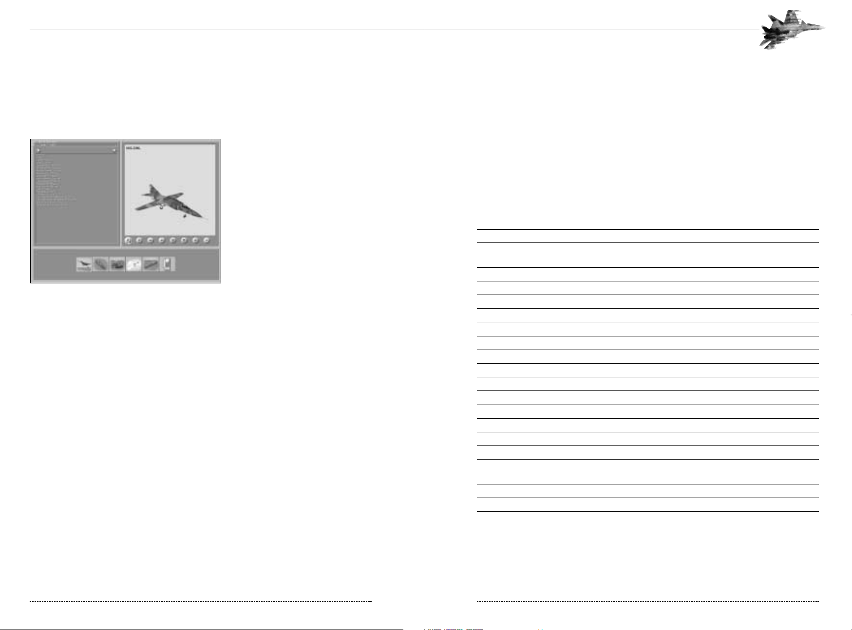
Encyclopedia
The encyclopedia provides an online
reference for all air, land, and sea vehicles used in the simulation. Begin by
clicking on the category button to
select the object category you’re interested in, then cycle through the available entries by selecting the drop
down menu below it. The controls in
the upper lright part of the menu allow
you to change your view of the model.
2-9: The Encyclopedia
Troubleshooting
Flanker 2.0 is a very complex game with a lot of features that can enhance your gameplay, but
also drag on your performance (frame rate, graphics, etc.). In order to ensure that you have the
most enjoyment possible, please take into consideration the following:
Game Play
• While there are almost always bugs in a game (even though we hate to admit it), the majority of
problems that players see are not actually problems, but simply that the player did not understand how the game works. Please read the manual and the readme thoroughly.
• Patches, new missions, campaigns and information can be found at the Flanker 2.0 website:
www.flanker2.com
Computer Setup
• Ensure that you have the latest drivers for all of your hardware. The number one cause of graphics problems is old video card drivers.
• Defrag your hard drive. This should be done prior to installation of Flanker 2.0. Sometimes
Windows will say that you have a low fragmentation percentage and that you do not need to run
the defragmentation program. Defrag your hard drive anyways and your should get better performance.
• Run Scan Disk before you install also. This will help insure a clean installation.
FLANKER 2.0
FLANKER 2.0
24 CHAPTER 2: The Main Menu
Page 15
CHAPTER 3: Instrument Panel 27
The cockpit of the Su-27 can be divided into two main sections: the Instrument Panel and the
Head Up Display (HUD). The panel contains most of the flight instruments. The HUD displays the
main navigational and combat information; its detailed description is given below in a separate
section. A number of indicators, buttons and levers, including the Throttle, are located on the side
panels of the cockpit, but this manual does not describe them because of their unimportance to
this package.
INSTRUMENT PANEL
Use the Numeric Keypad to move your head around. A front view of the Instrument Panel (pilot’s
head is lowered down) is shown in the figure below. The layout of the instruments, controls and
their operation almost completely correspond to those of the real Flanker.
The Instrument Panel
CHAPTER 3
Cockpit
CHAPTER 3
Cockpit
Defense Visual Information Center - Department of Defense
Page 16
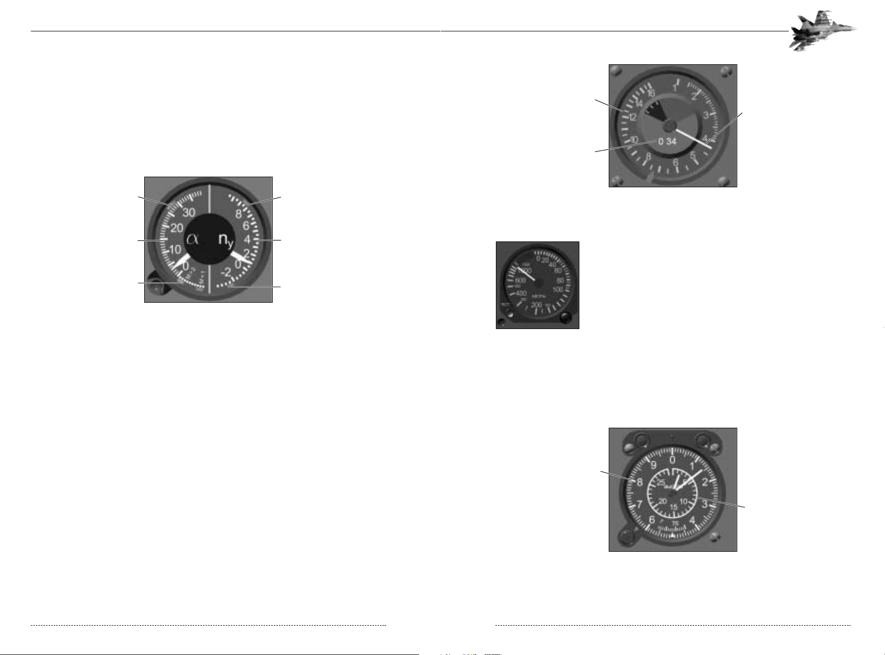
Radar Altimeter
The Radar Altimeter is right below the Combined G Meter & AOA
Indicator. It indicates the aircraft’s altitude in meters above the terrain.
The scale of the instrument is marked from 0 to 1000 meters and is
non-linear with larger spacing at lower altitude for increased precision.
Barometric Altimeter
Located below the ASI, the barometric altimeter measures the aircraft’s altitude above sea level.
The small needle uses the internal ring, ranging from 0 to 30km. The larger needle uses the
external ring and measures from 0 to 1,000m. Adding the two scales together shows the aircraft’s
altitude above sea level.
CHAPTER 3: Instrument Panel 29
Flight Instrumentation
Combined G Meter & AOA Indicator
This instrument is located in the upper left corner of the Instrument Panel. The scale of the AOA
Indicator (left side of the instrument) has uniform marks in the range from -20° to 40°. The red
mark on the scale marks the maximum operational angle of attack. On the right side of the instrument is the G-Load scale uniformly marked every 2 Gs from -4 to +10g.
Airspeed Indicator & Mach Meter (ASI)
The ASI is situated to the right of the G Meter and displays the current indicated airspeed (IAS)
and Mach number. While true airspeed (TAS) measures the aircraft’s speed against a fixed point,
IAS, on the other hand, takes into account the change in air pressure at altitude and how it affects
flight. At sea level, TAS and IAS are identical. At high altitude, IAS is much lower than TAS because
of the thinner atmosphere. A Flanker flying at 350km/hr IAS will have similar flight characteristics at
any altitude. IAS, in other words, accounts for the decreased pressure at higher altitude and the
subsequent decreased lifting capability of the wing. As a result, IAS provides a near constant
measure for stall speed, regardless of altitude.
The scale of the ASI is marked from 0 to 1600 km/h and is non-linear (the values of the scale
divisions grow with increase in speed). The three-digit Mach number indicator reflects the ratio of
true airspeed to the speed of sound under the given flight conditions.
FLANKER 2.0
FLANKER 2.0
28 CHAPTER 3: Instrument Panel
Maximum Positive AOA Maximum Positve G
G Load Scale
Maximum Negative G
AOA Scale
Maximum Negative AOA
Indicated Airspeed Scale
Airspeed Indicator Needle
Mach Number
Outer Scale
(0 to 1 km)
Inner Scale
(0 to 30 km)
Page 17
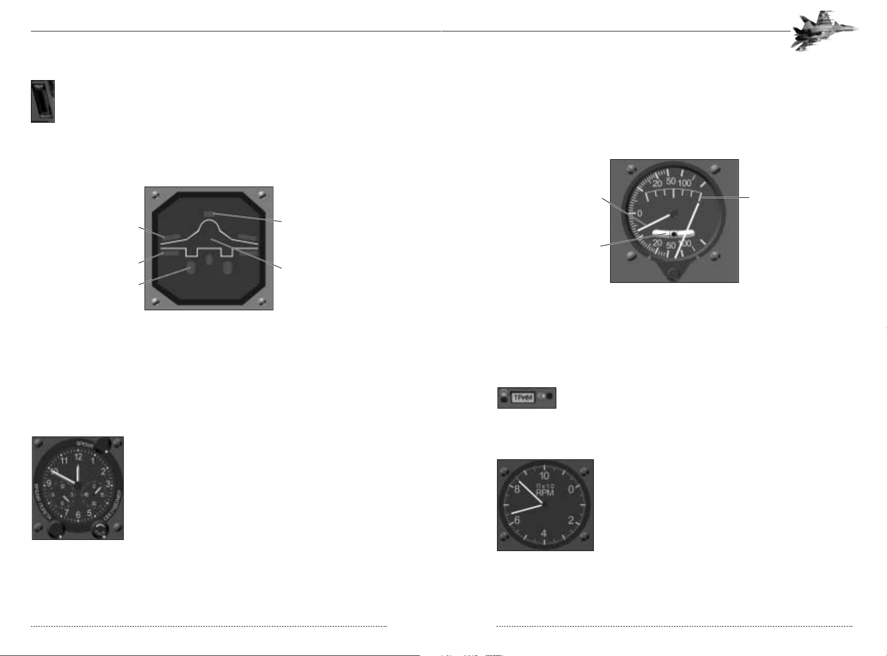
Variometer
The Variometer is situated between the Attitude Direction Indicator and the RPM Indicator and
shows your current rate of climb and turn. The scale of the instrument is non-linear ranging from
200 m/s (climb) to -200 m/s (dive). Thus, in the area of zero vertical speed the scale has the highest accuracy. The rate of turn scale ranges from 3°/sec left to 3°/sec right with a 1-degree interval.
The small ball on the sideslip scale slides in the direction of the aircraft’s sideslip. This indicator is
used to coordinate the input of rudder to help to coordinate turns. The pilot “steps on the ball”
(applies rudder on the same side as the ball) to center it in the indicator...
Neutral Trim Indicator
This indicator is located right below the Horizontal Situation Indicator. The
highlighting of the Neutral Trim Indicator means that the trimmer is in the
neutral position. As soon as you start to trim using the joystick coolie hat or
the trim control keys, the light is disabled.
RPM Indicator
The RPM Indicator is located to the left of the MFD. The scale of
the indicator is graduated from 0 to 110% in tens of percent. Two
separate needles measure port and starboard engine thrust. When
both engines are operating at the same thrust, it will appear that
only one needle is visible.
CHAPTER 3: Instrument Panel 31
Slats Indicator
The Slats (or leading edge flaps) Indicator is to the left of the Radio Altimeter. The white
portion of the bar indicates the position of the slats. The lower the white needle, the
farther the slats are released. Note that the slats on the Flanker are controlled automatically by the flight control system and configure to the optimum angle for the aircraft’s
attitude, angle of attack, speed, weight, and altitude.
Configuration Display
In the lower left-hand corner of the Instrument Panel below the Radar Altimeter is the
Configuration Display. It shows information about the positions of the landing gear, flaps, anti-FOD
screens, air brake and drogue chute (and the tailhook in the case of the Su-33). Illumination of
any indicator by a green light means that the corresponding control is in the active position, i.e.
deployed. A flashing green light means that the control is in movement. The anti-FOD screens are
automatically actuated on take-off and landing.
Clock
The clock shows the current time within
the simulation.
FLANKER 2.0
FLANKER 2.0
30 CHAPTER 3: Instrument Panel
Anti-FOD Screen
Speed Brake
Drogue Chute
Flaps
Landing Gear
Vertical Speed Indicator
Turn Rate Scale
Slip Indicator
Page 18
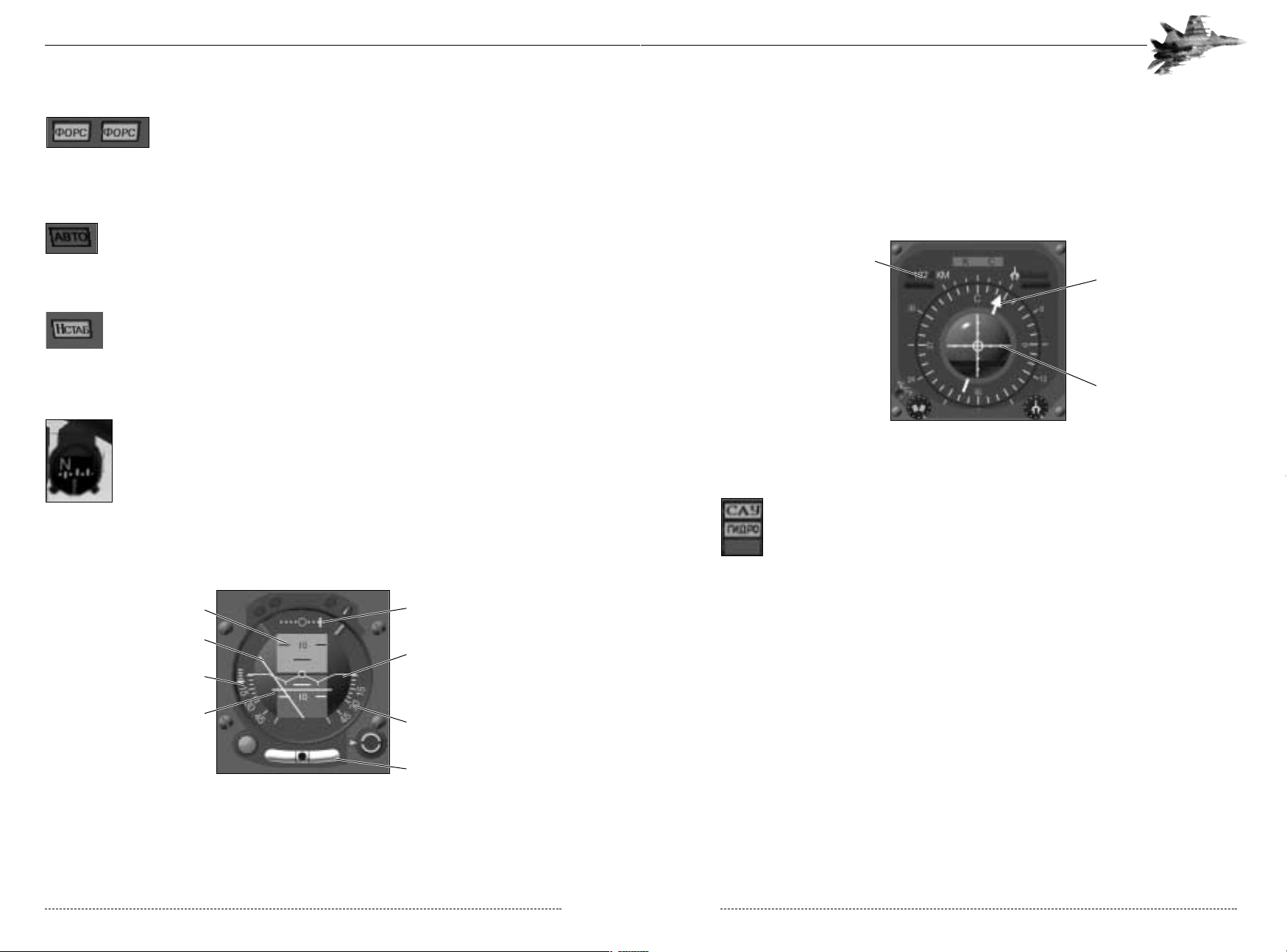
The mobile Pitch Scale and the Aircraft Datum (symbolic image of the aircraft in the center) show
the aircraft’s spatial orientation with respect to the horizon. The ADI also receives control information on the pitch angle, bank, heading, and altitude required to reach the next navigation waypoint.
This information is supplied by the navigation system, and it enables the pilot to manually fly the
Flanker and follow a specific flight plan.
Horizontal Situation Indicator (HSI)
Automatic Control System Failure Indicator
The illumination of the ACS Failure Indicator CFE (pronounced “sau,” stands
for Automatic Control System) located to the right of the HSI signifies a failure of
the Automatic Control System. This indicates a disturbance and/or failure in the
operation of Autopilot and Altitude Stabilization systems.
Hydraulic System Failure Indicator
The Hydraulic System Failure Indicator UBLHJ (pronounced “gid-ro,” stands for HYDRO) is just
below the ACS Failure Indicator. This kind of failure results in the loss of control of the flaps, slats,
and the air brake, plus diminished authority of elevator, rudder and flaperons.
CHAPTER 3: Instrument Panel 33
Afterburner Engaged Indicators
The Afterburner Engaged Indicators are right above the RPM indicator.
They are highlighted when the afterburner lights and engine RPM exceeds
100%. The word AJHC on the indicators (pronounced “fors”) which is
short for “forsazh) denotes “afterburner” in Russian.
Autopilot Engaged Indicator
Illumination of this indicator located to the right of the Configuration Display designates operation of the Automatic Control System in autopilot mode. The Russian
FDNJ (pronounced ‘af-to’) denotes autopilot, and is toggled by the A key.
Altitude Stabilization Indicator
The Altitude Stabilization Indicator is to the right of the Autopilot Engaged Indicator
below the Barometric Altimeter.The Russian Y-CNF< (pronounced ‘ash-stab’.)
denotes that the Automatic Control System is in altitude stabilization mode. Toggle
the altitude stabilization mode with the H key.
Magnetic Compass
The forward frame of the cockpit canopy houses three rearview mirrors and the
Magnetic Compass. The compass consists of a ball with a scale, which is
enclosed in a casing and plunged in a liquid. The scale on the ball is marked in
30° increments and has designations of the cardinal points (North, West, South
and East).
Attitude Direction Indicator (ADI)
In the center of the Instrument Panel just below the Weapon Readiness Indicator is the Attitude
Direction Indicator (ADI) or artificial horizon. It is the main navigational instrument, especially in
zero visibility conditions.
FLANKER 2.0
FLANKER 2.0
32 CHAPTER 3: Instrument Panel
Pitch Scale Required Heading Indicator
Aircraft Datum
Bank Scale
Slip Indicator
Required Bank Indicator
Required Altitude Indicator
Required Pitch Indicator
Distance To Beacon
Heading to Beacon
ILS Lines
Page 19
Combat Instrumentation
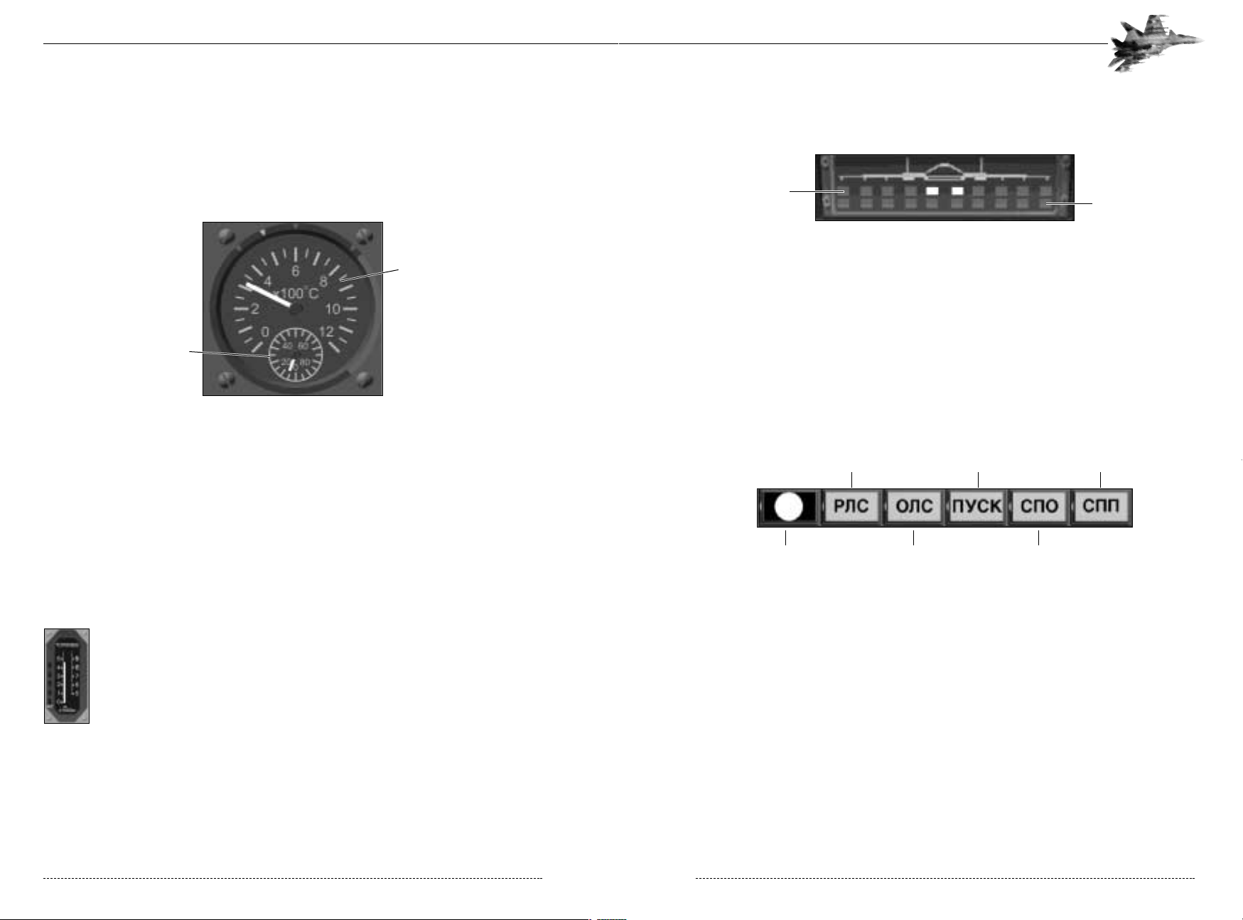
Weapons Readiness Panel.
This indicator is located just below the HUD and shows the location and readiness of the available
weapons hanging on 10 underwing and fuselage pylons. The illuminated lights in the upper row
indicate the presence of weapons on the pylons, and those in the lower row the readiness of the
corresponding weapons to instant use. Note that such readiness is governed not only by the
selection of the weapon, but also by the specific combat situation.
Master Warning Panel Failure Lights
Located just below the Weapons Readiness Panel, the Warning Panel provides visual and audible
alerts to system failures and launch warnings. It consists of five indicators:
• Master Warning Light: The flashing red Master Warning Light accompanied by beeps
attracts your attention to vital information such as ground proximity, stall, damage to any systems
of the aircraft, low fuel, illumination of your aircraft by radar and others. The Master Warning
Light is the main form of notification when the following system damage failures, or other events
occur: gear up of down, launch authorization, Gmax or AOA max, out of fuel, or minimum or
maximum speed reached.
• HKC(“rls”) Radar Failure
• JKC(“ols”) Electro-Optical System Failure
• GECR(“pusk”) Missile Launch Warning
• CGJ(“spo”) Radar Warning System Failure
• CGG(“spp”) Missile Launch Warning System Failure
CHAPTER 3: Instrument Panel 35
Jet Pipe Temperature Indicators
The two indicators located to the right of the HSI show jet pipe temperature of gases at the turbine exhaust of both AL-31F engines. Each indicator consists of two circular scales, the large
scale ranging from 0 up to 1000° Celsius and showing the temperature in hundreds of degrees.
The small scale renders more precise the reading taken from the large scale and has a range of
100°C in tens of degrees. Exact temperature is read by combining the two scales.
Maximum Engine Temperature Indicators
Located just below the Jet Pipe Temperature Indicators are the Max Engine Temperature
Indicators. Critical jet pipe temperatures are symptoms of impending engine failure, engine compressor failure, missile strike, etc.
A failure of the power plant often leads to a spontaneous increase of gas temperature at the turbine exit and a drop in RPM. This situation is immediately reflected on the RPM Indicator and the
Jet Pipe Temperature Indicators.. An engine on fire or suffering catastrophic failure will shut down
automatically and a powerful halogen extinguisher will be released into the engine area.
Fuel Gauge
The Fuel Gauge is to the right of the Jet Pipe Temperature Indicators. It indicates
total fuel remaining in the tanks. The vertical scale of the instrument is marked in
tons and uses two scales to measure from 0 to 9 tons. The scale on the left marks 0
to 5 tons; the scale on the right marks 5 to 9 tons.
At the top of the Fuel Gauge is the NJHKBJ light (denotes “fuel” in Russian, should
be pronounced “top-li-vo”). When this is highlighted, you are on your reserve fuel,
and its definitely time to return to base as things could be going awfully quiet soon.
But don’t panic too much as the reserve guarantees successful flight to the nearest diversion
airfield in case a landing is impossible on the initial airfield (runway destroyed, poor visibility, etc.).
FLANKER 2.0
FLANKER 2.0
34 CHAPTER 3: Instrument Panel
Inner Scale
Outer Scale
Position Loaded Lights
Position Active Lights
Master Warning Light
Radar Failure
Missile Launch
Warning
Missile Launch Warning
System Failure
EOS Failure
Radar Warning
System Failure
Page 20

Active Jamming Indicator
Below the Chaff/Flare Counter is the Active Jamming Indicator FG (“ap”). This
indicator shows activity of the built-in and/or additional Sorbtsiya active jamming
system. If the indicator is not highlighted, your active jamming system is damaged
or turned off. The active jamming system is toggled by the E key.
MULTI-FUNCTION DISPLAY (MFD)
The Multi-Function Display (MFD) dominates the right-hand side of the instrument panel. The
MFD is the most versatile of all instrumentation in the Flanker, displaying different types of data
depending on the selected avionics mode. The MFD generally displays a “top down” view, with
the symbology and objects displayed varying depending on the selected avionics mode.
Each avionics mode is described, complete with illustrations of the MFD symbology, in the
Avionics chapter.
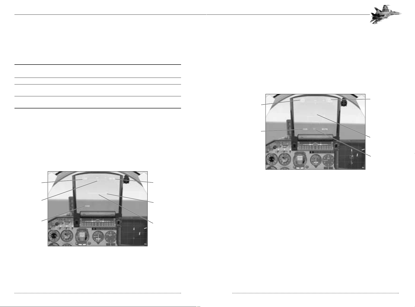
HEAD UP DISPLAY (HUD)
The most important multi-function instrument of the Flanker is the Heads-Up Display (HUD). The
HUD displays a wide variety of flight attitude, navigation, weapons, and targeting information
depending upon the selected avionics mode. Generally speaking, the HUD always displays your
airspeed (in km/hr), your altitude (in meters), your heading, and your flight attitude (pitch and
bank). The altitude display will vary between MSL (altitude above mean sea level) and radar AGL
(altitude above ground level). When displaying AGL, the symbol H (the Russian letter “R” for
“Radar Altimeter) appears next to the altitude display. Radar altimeter data is valid only when
banking less than 45 degrees or pitching less than 70 degrees. The HUD also displays the currently selected avionics mode in the lower left corner. By default, the mode name is displayed in
Russian; you can configure this to English via the Options menu. The possible modes are:
CHAPTER 3: Multi-Function Display (MFD) 37
Chaff/Flare Counter
Below the MFD is the Chaff/Flare Counter, which shows how many APP-50 combined chaff and flare dispensers remain at your disposal. The initial value of the
counter is 32 for the Su-27 and 51 for the Su-33. The counter reads zero if the
chaff/flare deployment system is damaged or you’ve run out of dispensers. Pressing the ALT-Q
toggles the continuous dispenser on or off. When activated, the dispenser will deploy chaff and
flares until either the player turns the dispenser off or the supply of chaff and flares is exhausted.
Threat Warning Display
In the lower right-hand corner of the cockpit is the Threat Warning Display (TWD). It depicts
information on enemy illumination sources detected by the SPO-15 ‘Beryoza’ Radar Warning
System. Such sources can be enemy aircraft, radar of SAM installations, AWACS, and so on.
Lights surrounding the aircraft’s silhouette show the approximate bearing of the illumination
source: if the aircraft falls within radar coverage, the corresponding light flashes at a frequency
characterizing the periodicity of illumination, and the audio alarm beeps. In the event of a “lock on”
the red Lock-On Indicator is continuously illuminated.
In the lower part of the TWD are 5 lights indicating the type of radar that has locked onto your aircraft. The Radar Warning System provides for the identification of the following types of radar:
1 - airborne radar
2 - radar of a long-range SAM system
3 - radar of a mid-range SAM system
4 - radar of a short-range SAM system
5 - early warning radar (airborne or ground-based).
FLANKER 2.0
FLANKER 2.0
36 CHAPTER 3: Instrument Panel
Ranging Lines
Your Aircraft Position
Mode-Specific Display
Ranging Scale
Threat Bearing Indicators
Radar Type Indicators
Lock-On Detected
Page 21
CHAPTER 4: Introduction to Avionics & Combat Systems 39
INTRODUCTION TO AVIONICS &
COMBAT SYSTEMS
Flanker 2.0 offers a complex and realistic portrayal of the real-world avionics suite found in the
Su-27 and Su-33. By Western standards, these systems are generally regarded as inadequate,
creating high pilot workload. To get the most out of the Flanker, you must learn how to operate its
systems and how to cope with its design limitations.
All HUD displays fall into one of three categories: navigation, air-to-air combat, or air-to-ground
combat. Sub-modes organize and display different types of information. Generally speaking, it’s
not necessary to utilize every sub-mode for each category; however, each sub-mode is designed
for a particular task.
Russian vs English Displays
To create the most authentic simulation of a Russian aircraft, all displays and HUD indicators
default to the Russian language with Cyrillic characters. You may, however, switch the displays
between English and Russian language in the Options menu under “miscellaneous.” Please note:
regardless of the language used, all displays will still use metric units. Altitude is measured in
meters and airspeed is measured in Kilometers per hour.
CHAPTER 4
Avionics and Combat Systems
CHAPTER 4
Avionics and Combat Systems
RUSSIAN DESIGNATIONS ENGLISH DESIGNATIONS PURPOSE
YFD (NAV) NAV (Navigation) Basic navigation mode, heading + stopwatch.
SUBMODES: SUBMODES:
VFHY (MARSH) ENR (En-route) Follow flight path.
DJPD (VOSV) RTN (Return) Return to selected airfield.
GJC (POS) LNDG (Landing) Land on selected airfield. ILS approach.
YFD (DVB) BVR (Beyond Visual Range) Engage airborne targets at long ranges.
SUBMODES: SUBMODES:
J<P (SKAN) SCAN (Scan) Scans a mximum of 24 contacts.
CYG (SNP) TWS (Track While Scan) Tracks 8 contacts while scanning up to 16 contacts.
(DRLO) AWACS Displays contacts from AWACS datalink.
FNR (ATK) ATK (Attack) One target locked-up.
<D< (BVB) CAC (Close Air Combat) Dogfight at close range.
CNH (STR) BORE (Radar Bore Site) Aim using forward looking bore site of
radar beam.
ABJ (FIO) LNGT (Longitudinal Aim using the selected missile guidance system at
missile aiming) visual ranges.
IKTV (SHLEM) HMTD (Helmet-Mounted Engage agile targets using helmet-
Target Designator) mounted target designator.
PTVKZ (ZEMLYA) GND (Ground Attack) Destroy ground targets.
GH (PR) LA (Shoot) Authorized to fire weapon.
JND (OTV) NO LA (Don’t Shoot) Not Authorized to fire weapon.
Each avionics mode is described, complete with illustrations of the HUD symbology, in the
Avionics chapter.
FLANKER 2.0
FLANKER 2.0
38 CHAPTER 3: Multi-Function Display (MFD)
YOUR SPEED
YOUR ALTITUDE
FLIGHT PATH MARKER
CURRENT PITCH &
BANK DATA
HUD MODE
GLIDE PATH INDICATOR
LIGHTS (SU-33 ONLY)
RANGE TO SELECTED OBJECT
(TARGET, AIRFIELD, NAV POINT)
SUBMODE
REQUIRED SPEED HEADING REQUIRED ALTITUDE
Defense Visual Information Center - Department of Defense
Page 22
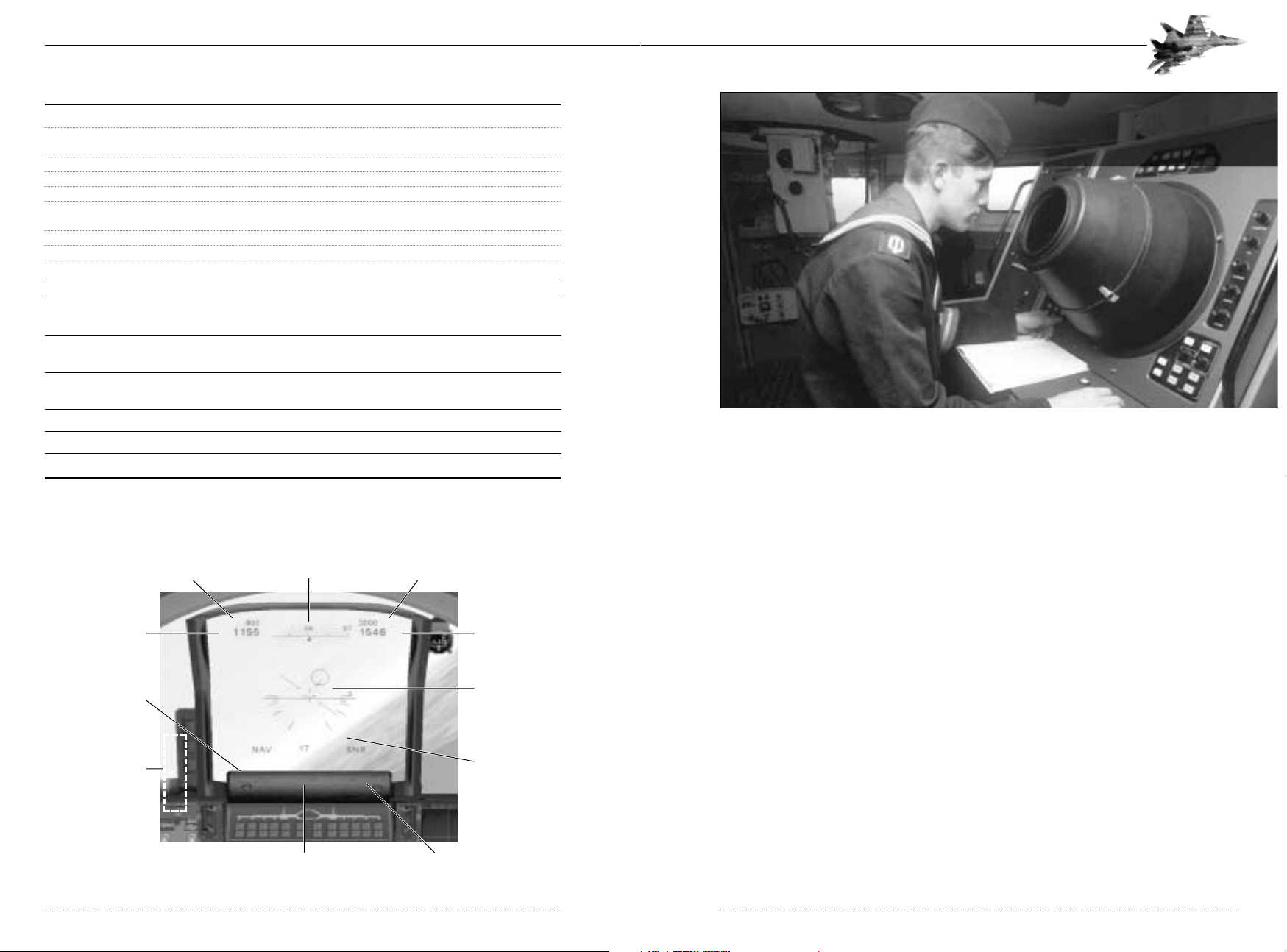
VFHI (ENR) - Enroute Submode
The VFHI (ENR) submode is the primary navigation submode, enabling the pilot to fly the predetermined mission flight profile. Select it by pressing the 1 key while in the initial NAV or Piloting
mode. Each waypoint is characterized by its coordinates on the ground, its altitude, and the
desired airspeed for that leg of the trip. This mode displays the required speed and altitude of the
waypoint in small characters located above the actual speed and altitude readouts of the aircraft.
A circle or navigation reticle, inside the HUD points the way to the next waypoint. Manoeuvre the
aircraft to center the navigation reticle in the HUD and you’re heading directly to the next
waypoint. Numbers in the center of the HUD’s bottom edge indicate the distance to the next
waypoint in kilometers.
4-2: The VFHI (ENR) Submode
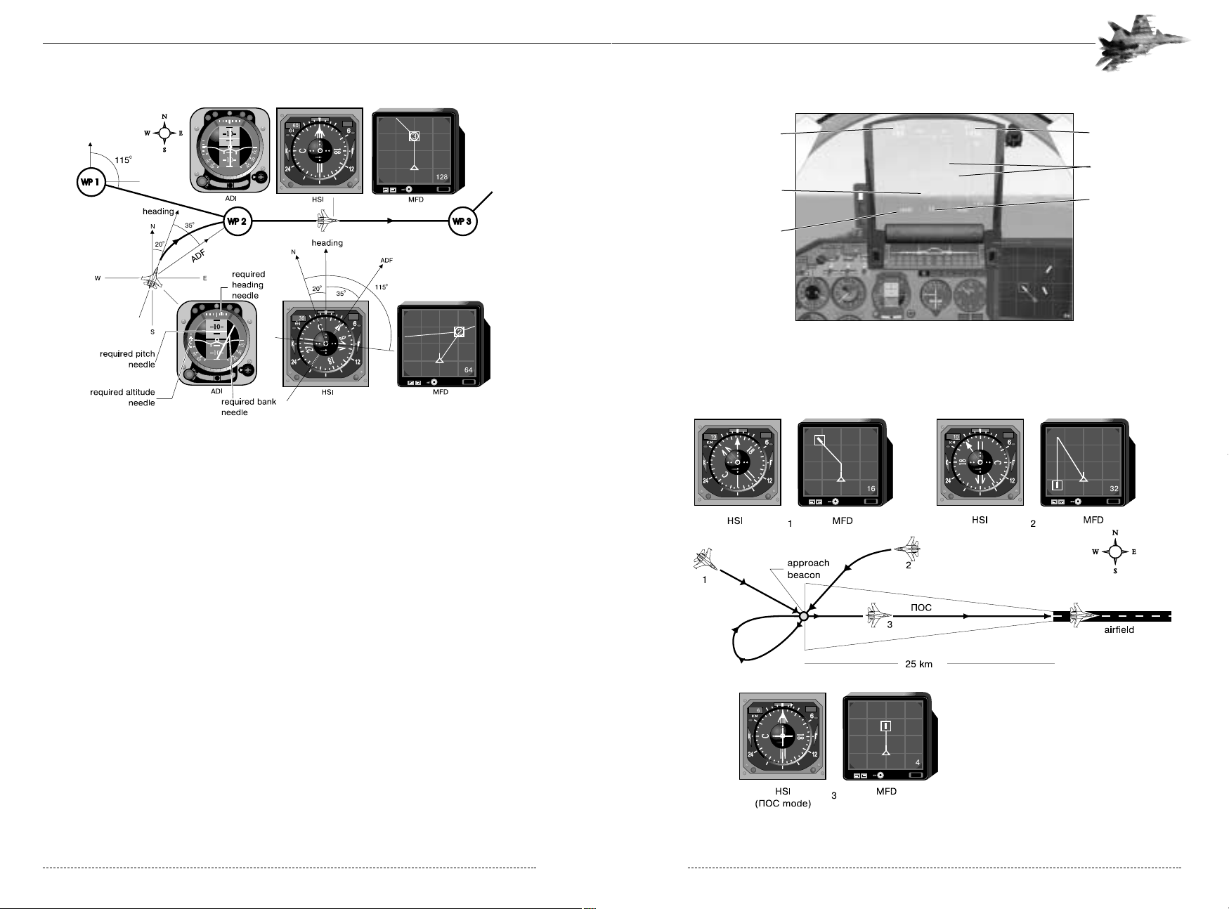
Backup Instruments
The instrument panel also provides navigation information. The MFD symbolizes your position, the
waypoint , and the desired flight path to the next selected waypoint. The ADI yellow predictor bars
(“needles”) mark the desired bank and pitch angles while the HSI shows the required heading
and distance to the next waypoint. In general, if the HUD becomes unservicable, you can still navigate using the instrument panel.
The VFHI (ENR) submode provides no combat information. Generally speaking, select this
mode, set your course, and then select a more appropriate combat mode. Occasionally return to
VFHI (ENR) mode to verify your flight path. Press the ~ key to cycle through waypoints.
CHAPTER 4: Navigation 41
NAVIGATION
The navigation modes are your primary means of finding your way around the simulated battlefield. There are four navigation submodes.
RUSSIAN PRONOUNCED ENGLISH MODE TYPE PURPOSE
DESIGNATION DESIGNATION
YFD “nav” NAV Piloting Visual navigation with a compass and
stopwatch
VFHI “marsh” ENR Enroute Enroute navigation
DJPD “vosv” RTN Return Return to the Initial Approach Fix at
the home airbase.
GJC “pos” LNDG Landing Activates the Instrument Landing System (ILS)
and autoland feature (for carrier operations.)
To select the navigation category press the 1 key. This selects the default navigation mode, Piloting.
Cycle through the various individual navigational submodes by hitting the 1 key repeatedly.
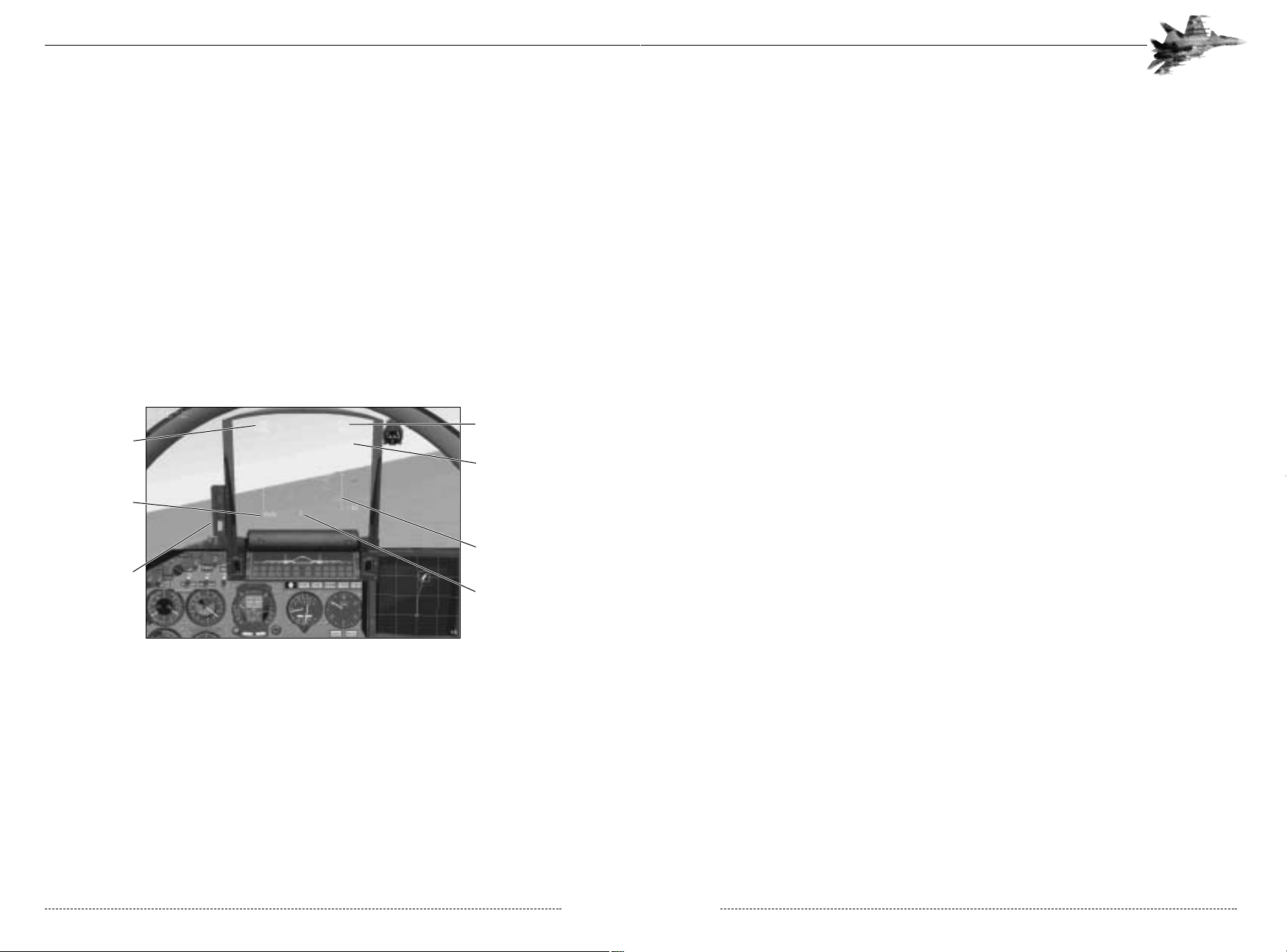
YFD–(NAV) – Piloting Mode
The piloting mode is the initial navigation mode, automatically displayed whenever you first press the 1
key while in another mode. This mode provides only minimal information. The HUD shows airspeed,
altitude, and flight attitude information while the MFD shows airfields and the Admiral Kuznetzov
aircraft carrier, if present. Use this mode for free-form flying without any pre-determined plan.
4-1: The YFD (NAV) - Piloting Hud
FLANKER 2.0
FLANKER 2.0
40 CHAPTER 4: Navigation
Airspeed Altitude
Pitch Angle
Aircraft Datum
Heading
NAV Mode Selected
Required Airspeed
Required Altitude
Waypoint Steering Cue
Distance to Waypoint
On Route Mode Selected
Page 23
4-4: The DJPD (RTN) - Return Submode
You select the DJPD (RTN) submode by pressing the 1-key twice from the initial NAV mode. You
may cycle through the available runways and their IAFs by pressing the ~ key.
4-5: Reading the DJPD (RTN) - Return Submode Instrumentation
CHAPTER 4: Navigation 43
4-3: Reading the VFHI (ENR) Submode instrumentation
In figure 4.3 the aircraft on approach to waypoint 2 is misaligned by about 35 degrees to the left.
This is reflected on the HSI (see the instruments at the bottom of the figure): the current heading
is 20 and the ADF arrow (the narrow needle) reads 55 degrees. The distance to waypoint 2 is
30km (upper left corner of the HSI). The desired radial, the desired flight path from waypoint 1 to
waypoint 2, is shown by the flight path marker (the wide needle). In other words, the ADF needle
points directly to the next waypoint while the flight path marker points to the pre-programmed
flight path to that same waypoint.
The ADI also shows the misalignment between the aircraft’s heading and the next waypoint. The
required bank needle points to the right, indicating the aircraft needs to turn to the right to reach
the next waypoint. If the aircraft were on course, the needle would point straight up. The required
altitude needle on the left of the ADI shows that the aircraft is quite close to the desired altitude.
If the aircraft is on the planned flight path, as is the aircraft between waypoints 2 and 3 in the
same figure, then the wide and narrow arrows on the HSI are aligned and pointing straight up.
Likewise, the required bank needle on the ADI is also pointing straight up.
DJPD (RTN) - Return Submode
The DJPD (RTN) submode directs you to the Initial Approach Fix (IAF) for the runway you are
landing at. Think of the IAF as the last waypoint before reaching the airbase, where you will intercept the Instrument Landing System (ILS) and begin your approach. For all intents and purposes,
DJPD (RTN) is identical to VFHI (ENR) except that DJPD (RTN) only has one waypoint: the
IAF for the runway.
FLANKER 2.0
FLANKER 2.0
42 CHAPTER 4: Navigation
Required Airspeed Required Altitude
Distance to Approach Point
Steering Cue
Return Mode Selected
ILS Bars
Page 24
RADAR AND ELECTRO-OPTICAL SYSTEM
The weapons control system (WCS) of the Su-27 and the Su-33 integrates the weapon and target
data and parameters from the following components:
• The Zhuk-27 or Miech-33 airborne radar;
• The 36-Sh Electro-Optical System (EOS);
• The onboard weapons management software;
• Individual weapon targeting hardware and software;
• The data presentation system (MFD and the HUD);
• The Parol (Password) Identification Friend or Foe (IFF) interrogator which processes signals from
air and ground installations equipped with pertinent transponders;
• The Helmet-Mounted Target Designator (HMTD);
• Target data feed from AWACS.
Zhuk-27 radar (Su-27)
The Phazotron Zhuk-27 (Beetle) coherent pulse-Doppler jam-proof radar is fitted with a twist
cassegrain antenna of 700 mm in diameter and has the following features:
Air-to-air mode
• Look/down-shoot/down capability;
• Range-while-search of up to 24 contacts;
• Track-while-scan of up to 8 contacts;
Miech-33 radar (Su-33)
The Phazotron Miech-33 (Shield) is also a coherent pulse-Doppler jam-proof radar with the same airto-air characteristics as the Zhuk-27, but additionally offers a powerful air-to-surface mode.
Air-to-air mode
• Look/down-shoot/down capability;
• Range-while-search of up to 24 contacts;
• Track-while-scan of up to 8 contacts;
Air-to-surface mode
• Real beam ground mapping;
• Doppler beam sharpening;
• Synthetic aperture;
• Map enlargement/freezing capability;
• Detection and tracking of moving ground or seaborne targets;
• Air to surface ranging.
CHAPTER 4: Radar and Electro-Optical System 45
When flying towards the IAF, the wide arrow on the HSI always indicates he bearing from the beacon to the selected airfield and normally is the same as the runway heading. Figure 4-5 illustrates
the readings of the HSI and the MFD for three aircraft with different positions relative to the
approach beacon. Aircraft 1 is 10km from the beacon and flying a heading of 135, on track to the
IAF. Aircraft 2 is 10km from the IAF, flying a heading of 270. The misalignment between the current
heading and the required heading is 35 degrees. In other words, the pilot must turn 35 degrees to
the left to fly directly to the IAF. Aircraft 3 is flying the runway heading, between the runway and the
IAF. In this case, the MFD shows only a straight line from the runway to aircraft marker.
When the aircraft reaches the IAF, the navigation software automatically switches to the GJC
(LNDG), or landing, submode.
GJC (LNDG) Landing Submode
You can, however, switch directly to Landing submode by pressing the 1 key repeatedly until the
GJC (LNDG) indicator is displayed on the HUD. If the airfield is equipped with an ILS, the
Glideslope and Localizer bars are displayed. A vertical velocity scale will appears on the right side
of the HUD. The ideal touchdown should occur at a sink rate of 1 to 1.5 m/s.
4-6: The GJC–(LNDG) Landing Submode with ILS
For more information on landings, see the section on landings in Chapter 5, Ground School and
the appropriate training missions in Chapter 7, Training.
FLANKER 2.0
FLANKER 2.0
44 CHAPTER 4: Navigation
Required Airspeed
Required Altitude
Vertical Velocity Scale
Current Vertical Velocity
Distance to Runway
Return Mode Selected
AOA Indexer
Page 25

To toggle the EOS, press the O key. The EOS Cue N (stands for ‘Thermal’) on the left side of the
HUD indicates that the EOS is active If the EOS Cue does not appear at all, this indicates that the
EOS is either damaged or not correctly selected.
The EOS, radar, or a missile’s seeker can be slaved to the pilot’s helmet-mounted target designator (HMTD) allowing the pilot to target simply by moving his head in the direction of the enemy
aircraft. This is extremely convenient for acquiring agile targets at visual ranges.
Since the principles of using the radar and the EOS are practically the same, we describe these
principles for the various combat modes in the same place, pointing out distinctions as needed.
Scan Cone Basics
To understand how the radar/EOS searches for targets, imagine walking through a forest with a
flashlight on a pitch-black, moonless night. You can only see objects illuminated by the flashlight
beam, and the beam grows weaker as it extends from the light bulb. This essentially describes the
problems using radar to search for targets. In simple terms, the radar extends something like a
cone in front of the transmitter. The farther it goes, the bigger the cone gets. Objects outside of
the cone will pass undetected. As a result, it is necessary to turn the aircraft occasionally and to
“slew” the scan cone using the Shift - ; (up)Shift - . (down) Shift - ‘ (left)Shift - / (right) keys,
much like moving the flashlight around the darkened forest.
Objects inside the cone will reflect radar energy back toward the transmitter. But, radar waves lose
power as they travel. If they travel far enough, they eventually dissipate. Consequently, contacts at
long range may not reflect enough radar energy; the reflected waves dissipate before making it
back to the transmitter. Therefore, if the radar energy can travel 150km, bounce off a target, and
return 150km to the source, then the radar energy is also capable of travelling at least 300km in a
straight line. This means that the enemy can detect your radar transmissions from well outside of
your effective search range!
The EOS works similarly, except that it is a passive system; instead of looking for reflected radar
waves, it looks for heat emitted by targets. As a general rule, hotter targets (fighters using afterburner) can be detected further away. Also, rear-aspect targets (with the heat source pointed at
the EOS) will generally be detected further away than nose-aspect targets (since the enemy aircraft is blocking the view of the engine exhaust).
CHAPTER 4: Radar and Electro-Optical System 47
Radar Cross Section (RCS) of the target, or the size of the reflecting surface of the target, has
a substantial impact on radar detection performance. In general, large targets reflect more radar
energy, so a B-52 can be detected farther away than an F-16. For a target with an effective RCS
of 3 m2 (a typical sized fighter) the Zhuk-27 has a maximum detection range of 150 km (93 miles)
when facing the target’s forward hemisphere and 55 km (34 miles) when facing the target’s
rear hemisphere.
The radar transmits radio pulses of nearly equal frequency (within the X-band) and phase (coherent radiation). The radar measures the range to the target by timing how long it takes for the
reflected waves to return to the transmitter. The greater the range, the longer it takes the waves to
return. When the pulses are reflected from a moving target, the frequency shifts due to the
Doppler effect. Pointing the radar at the ground, naturally, results in lots of radar reflections
appearing on the scope. These returns are called ground clutter. Most modern radar systems
take advantage of the Doppler effect and filter out any returns that are stationary, thus filtering out
the extra returns from ground clutter. This does have one side effect, however, an airborne target
that has no movement relative to the transmitter appears stationary and is filtered out. This condition typically occurs when the target moves perpendicular to the transmitter, and therefore
appears stationary (in terms of how fast the transmitter is closing on the target). This effect is
called “beaming” and is an effective defense against airborne radars.
You toggle the radar by pressing the I key. The Radar Cue B (Russian “I”, stands for ‘illumination’)
on the left of the HUD indicates that the radar is active. If the Radar Cue does not appear when
you enable the radar, this means that latter is damaged.
36-Sh Electro-Optical System
See EOS The radar is backed up by the 36-Sh electro-optical system (EOS) designed by the NPO
Geophysica. The EOS can acquire thermally contrasting targets with high accuracy. It combines a
laser rangefinder (effective tail-on range of 8 km/5 miles) and Infra-Red Search and Track (IRST)
system (maximum effective range of 50 km/31 miles). These use the same optics, which consist of
a periscopic system of mirrors and an articulated glass sensor ball mounted centrally in front of
the windscreen. The sensor ball moves in elevation (-15° down and +60° up) and in azimuth (60°
left and 60° right of center, respectively). The information update rate depends on the field of view
size and varies from 2 (search in wide area) to 0.05 (autotrack mode) seconds.
The EOS operates passively (emits no detectable signal) by receiving infra red emissions from the
target. This allows the pilot to prepare a surprise attack on the enemy. Maximum detection ranges
depend on the attack geometry. It changes from 15 km for forward-hemisphere attacks to 50 km
for attacks in the rear hemisphere. The range to a target can be accurately measured only at relatively close distances (from 200m to 3 km). In order to measure distances outside laser range
when a target is locked (TAB Key) the radar sends short strobe bursts or pules towards the contact. Once the contact comes within 9 Kilometers, the strobe pulse ceases and the laser
rangefinder takes over. These pulses are extremely short and difficult to detect with accuracy, thus
providing little opportunity to locate the source. You mainly use the EOS to provide targeting data
for air-to-air missiles with an IR seeker head and for tracking targets in a guns fight.
FLANKER 2.0
FLANKER 2.0
46 CHAPTER 4: Radar and Electro-Optical System
Page 26

Air-to-Air Mode Summary
The following table lists the different avionics modes available for air-to-air combat. Note that they
fall into three categories: beyond visual range, close air combat, and longitudinal missile aiming.
FLIGHT / COMBAT MODE RUSSIAN ENGLISH KEY PURPOSE
Beyond Visual LD<-J<P BVR – SCAN 2 Acquire up to 24 tar
Range - Scan gets at 25 km to 150 km ranges.
Beyond Visual Range -Track LD<-CYG BVR - TWS 2 Tracking up to 8 contacts while scanning
While Scan up to 16 more.
Beyond Visual Range - LD<-LHKJ AWACS 2 Using AWACS information for attacking
AWACS Datalink targets when radar and EOS is off.
(Requires AWACS)
Close Air Combat – <<<-DC CAC – VS 3 Dogfight at ranges from visual to 25 km
Vertical Scan
Close Air Combat – <D<-CNH CAC – BORE 4 Aim using forward looking bore site of
Radar Bore Site radar beam.
Close Air Combat – <D<-IKTV CAC – HMTD 5 Aim using helmet-mounted target
Helmet designator.
Longitudional Aiming ABJ LNGT 6 Aiming using a missile’s seeker at ranges
from visual up to max IR/active range
of missile
Attack LD<-FNR BVR-ATK Tab Auto-tracking one target (Target Locked).
<D<-FNR CAC – ATK
ABJ-FNR FIO – ATK
LD< (BVR) Beyond Visual Range Mode
In LD< (BVR) Beyond Visual Range Mode, both the radar and the EOS scan in a limited area - the
scan cone has angular dimensions of 10° in the vertical plane (elevation scan angle) and 60° in the
horizontal plane (azimuth scan angle). You can move the radar/EOS scan zone within the gimbal
limits of the antenna/seeker. The scan zone dimensions of the radar are 120° x 120° , the EOS
dimensions are 120° horizontal, 60° up and 15° down (see the figure below). The radar beam
scans an area 2.5° tall, requiring four passes to the cover the entire scan cone. Each pass takes
about 0.5 seconds. Information on each radar contact, therefore, is updated every two seconds.
CHAPTER 4: Air-to-Air Combat 49
AIR-TO-AIR COMBAT
During an attack on an airborne target the pilot usually goes through the following steps: search,
locate, track, identify, and attack. He can accomplish these steps both with and without the radar
and/or the Electro-Optical System (EOS) . The selection of one or other type of weapon mainly
depends on the range to the target and the possibility of tracking the target using the onboard
radar or EOS.
The following table describes the main air-to-air HUD:
The table below is a summary of the keys you will often use in air to air combat.
KEY ACTION
I Toggle radar.
O Toggle EOS.
`
Select next AWACS contact on Multi-Functional Display (MFD)
Tab Place designated contact in Track While Scan from Scan
Ctrl-Tab Remove tracked contact from Track While Scan
Tab Lock tracked target to Attack Mode
Tab Lock/unlock target to Attack Mode in CAC submodes
; (Semicolon) Move HUD target designator UP
, (Comma) Move HUD target designator LEFT
. (Period) Move HUD target designator DOWN
/(Slash) Move HUD target designator RIGHT
Shift - ; (Semicolon) Move radar/EOS scan zone UP in BVR modes
Shift -, (Comma) Move radar/EOS scan zone LEFT in BVR modes
Shift -. (Period) Move radar/EOS scan zone DOWN in BVR modes
Shift - /(Slash) Move radar/EOS scan zone RIGHT in BVR modes
Ctrl+I Center radar antenna/ IRST ball
-(Minus) MFD/HUD Zoom in
+(Plus) MFD/HUD Zoom out
D Cycle through weapons
C Enable/disable cannon
Ctrl+V Toggle Salvo mode
Ctrl+W Jettison weapons/Load Weapons, step-by-step
FLANKER 2.0
FLANKER 2.0
48 CHAPTER 4: Air-to-Air Combat
Page 27
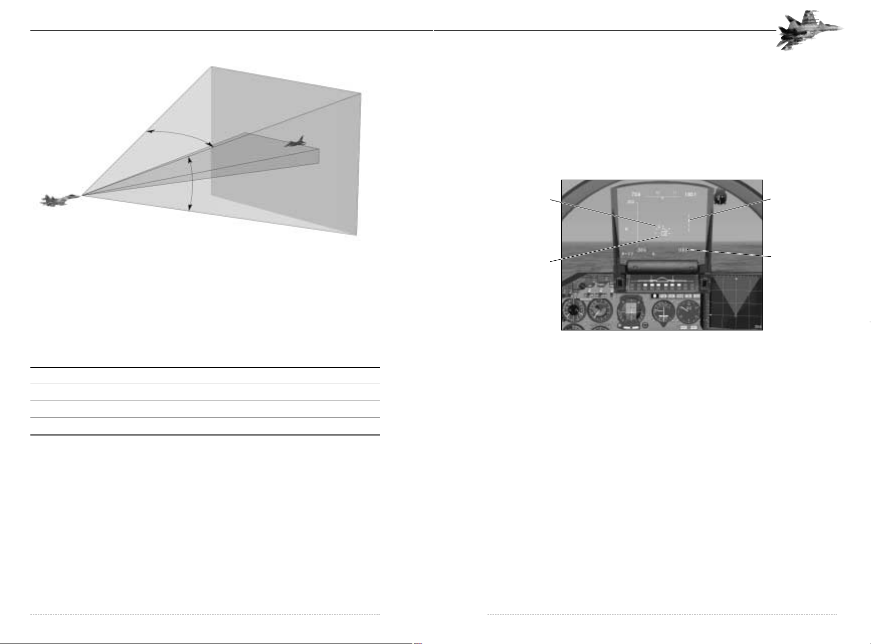
LD< – J<P (SCAN) Scan Submode
Pressing the 2 key selects LD< (BVR) mode in the J<P (SCAN) sub-mode of operation. This is
your primary, long-ranged search mode. It detects contacts (depending on RCS) from 25 to
150km away, displaying up to 24 contacts on the HUD. This mode does not provide any detailed
information about a specific contact. You’ll know the azimuth (how far the contact is off your nose)
and distance. You can also establish the contact’s elevation by the correlating the image return
and scan beam “illuminator” on the right side of the HUD.
4-8a: J<P (SCAN) Submode
To gather more information about specific contacts of interest, steer the HUD target designator
box over the desired contact (using the joystick coolie hat or the keyboard controls). Designate
the target by pressing Tab key. If the contact is within the track parameters of the radar, the HUD
switches to Track While Scan submode and the MFD will now display the designated contact.
Aspect information relating to the contact can now be viewed on the MFD. Alternatively, pressing
the 2 key immediately selects the eight closest contacts and switches to Track While Scan mode.
You cannot enter Track While Scan mode without designating at least one contact in Scan mode.
LD< – CYG (TWS) Track While Scan Submode
The
CYG
(TWS) Track While Scan submode focuses the radar/EOS “attention” on up to eight
contacts while continuing to scan and display range, azimuth, and elevation information on up to
16 others. The contacts on the MFD in TWS are continuously tracked by the radar.
On the HUD, a “tracked” contact changes from a dash to a small triangle. On the MFD, enemy
aircraft are displayed by triangle-like symbols, friendly aircraft are represented by circular symbols
and each tracked contact symbol has an aspect vector angle indicating direction and position relative to your aircraft. The MFD shows a top-down view of the area around your aircraft. Your
Flanker’s position is indicated by the aircraft symbol. The number in the upper corner of the MFD
indicates the distance in kilometers from the bottom edge of the MFD to the top edge. The closer
contacts are to the top edge, the farther away they are from your aircraft.
CHAPTER 4: Air-to-Air Combat 51
In BVR Mode, the radar antenna is stabilized in roll and pitch. This means that the direction of the
antenna axis does not change when the aircraft banks, pulls up or dives, providing that the aircraft
manoeuvres do not exceed the gimbal limits of the antenna. Unlike in many Western aircraft, the
beam shape of the Su-27’s radar is fixed and cannot be changed. The maximum detection
depends on the target’s characteristics (geometry, aspect angle, radar reflectivity, etc.). Typically,
the radar can detect a medium-size target such as a MiG-29 at a range of about 100-120 km.
Large targets such as strategic bombers can be detected at distances up to 150 km.
TARGET MAXIMUM DETECTION RANGE IN SCAN SUB-MODE, KM
B-52 150
F-111 80
F-16 50
F-117 @10
As with the radar, the field of search of the electro-optical system is stabilized in roll and pitch. The
EOS can detect medium-size targets located up to a maximum of 50 km. But, as described above,
cannot accurately measure the range to a target beyond 5 km.
Tracking data appears on both the HUD and the MFD, depending on the mode and submode
selected. In most cases, the MFD shows a top-down view of the area around your aircraft. Your
current position is indicated by the small aircraft symbol; the number in the corner indicates the
distance from the bottom edge to the top edge in kilometers. HUD and MFD symbology appropriate to each mode and submode are described in the following sections.
LD< (BVR) mode has three submodes of operation: Scan, Track While Scan, and Attack. The
following sections describe each mode.
FLANKER 2.0
FLANKER 2.0
50 CHAPTER 4: Air-to-Air Combat
Contacts
Range to Selected
Contact
Scan Sub Mode
Selected Contact
Page 28
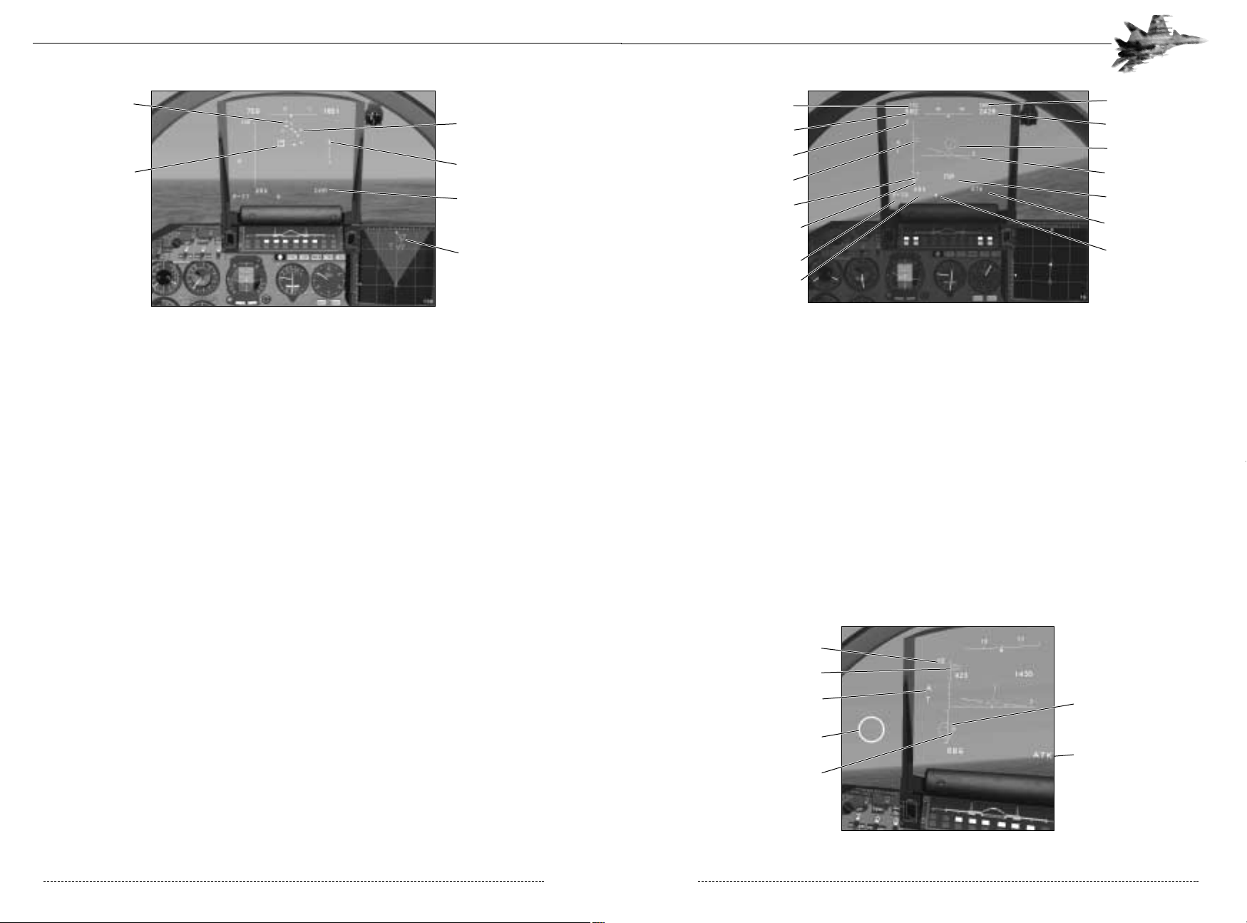
4-15: Autotrack Symbology with Radar Lock
Green lights on the Weapon Readiness Panel indicate which missiles at each weapons station are
ready for launch. The MFD displays a top-down view of the target, its aspect angle, and distanceinformation about the target. When you are tracking the target using the radar, target information
may disappear for some time if the target deploys ECM or decoy countermeasures.
The HUD will also display the GH (in English the designator will be LA for “Launch Authorized”)
Shoot Cue or JND (pronounced ‘o-te-ve’, stands for ‘TURN AWAY’ in Russian. In English the designator is No LA for “No Launch Authorized”) Reject Cue. The Shoot Cue informs you that the
selected missile is ready for launching and the target is within the missile’s reliable launch parameters. Fire the missile by pulling the trigger (Spacebar). The Reject Cue warns that you are too
close to the target and prohibits launch. If you lock onto friendly aircraft, the IFF (Ide CDJQ and
denotes “Ours”).
If the radar or the EOS switches to autotracking from Helmet Mode, cross-hairs superimpose on
the Targeting Circle (see the figure below). When the HUD gets the Shoot Cue, the Targeting
Circle flashes at a frequency of 2 Hz. If the onboard computer does not get target range information, the Targeting Circle flashes with a frequency of 1 Hz (this is common when using the EOS).
4-17: Autotrack Symbology with Helmet Mounted Sight
CHAPTER 4: Air-to-Air Combat 53
4-8a2:
CYG
(TWS) Submode
Attack (ATK) Submode
The Attack submode is common to all air to air modes. In short, you are requesting the radar to
focus all its energy onto one specific aircraft contact. Depending upon which mode you are operating (BVR, CAC), the method of selecting or designating that contact differs, but the end result is
the same: The radar/EOS will automatically track the aircraft contact, hence the term “auto-track.”
In common language this is called “the lock.” The radar/EOS receives all the necessary contact
parameters from the Weapons Control System to smoothly move the antenna in the direction of
flight for the contact. The following parameters are available on the HUD while the radar is in
auto-track:
• Aspect Angle relative to user aircraft • Azimuth/Elevation relative to user aircraft
• Distance relative to user aircraft • Speed of contact
Radar tracking area for a single target is 120°x 120° in elevation and in azimuth, and tracking
range for a medium-size target is from 55 km (rear hemisphere) to 100 km (forward hemisphere
for large aircraft). When operating in Attack Mode, the radar provides target designation for guided missiles, illuminates targets for missiles fitted with SARH seekers, and provides initial guidance
data for active missiles.
If you use the EOS, the tracking area coincides with its field of search and equals 75° in elevation
(15° down, 60° up) and 120° in azimuth. Tracking range depends on the type of target, strength
of the heat signatures, and the attack hemisphere. The EOS laser rangefinder measures distances
to the target for ranges from 0.2 to 3 km, with an accuracy of 10 meters and from 3 to 5 kilometers with and accuracy of 25 meters.
After the radar (EOS) has locked onto the target, the HUD shows the following information: the
‘À’ Autotrack Cue, the range scale with the minimum and maximum launch range marks, the
range to target mark, and the target aspect angle arrow. The HUD also displays the Aiming
Reticle, altitudes and true airspeeds of your aircraft and of the target, the aircraft datum and bank
scale, current combat mode, type of missile, quantity of missiles, and missile flight time. The target’s position is shown on the HUD as a point (the Target Marker) in angular coordinates scaled
to the dimensions of the tracking area (see the figure below).
FLANKER 2.0
FLANKER 2.0
52 CHAPTER 4: Air-to-Air Combat
Scanned Contacts
Selected Contact
Tracked Contacts
Tracked Contacts
Ranged Bar
Track While Scan Sub Mode
Target Airspeed
Target Altitude
Your Altitude
Target
Aircraft Datum
Shoot Cue
Autotrack Sub Mode
Weapon Quantity
Your Airspeed
5Km Range Scale
Target Range
Target Aspect
Weapon Minimum
Range Marker
Weapon Type
Master Mode
Helmet Mounted
Targeting Site
Autotrack Mode Active
Range to Target
10Km Range Scale
Target Designator Circle
(Remains Inside HUD Field
of View at All Times
Autotrack Sub Mode
Target’s Heading
Page 29
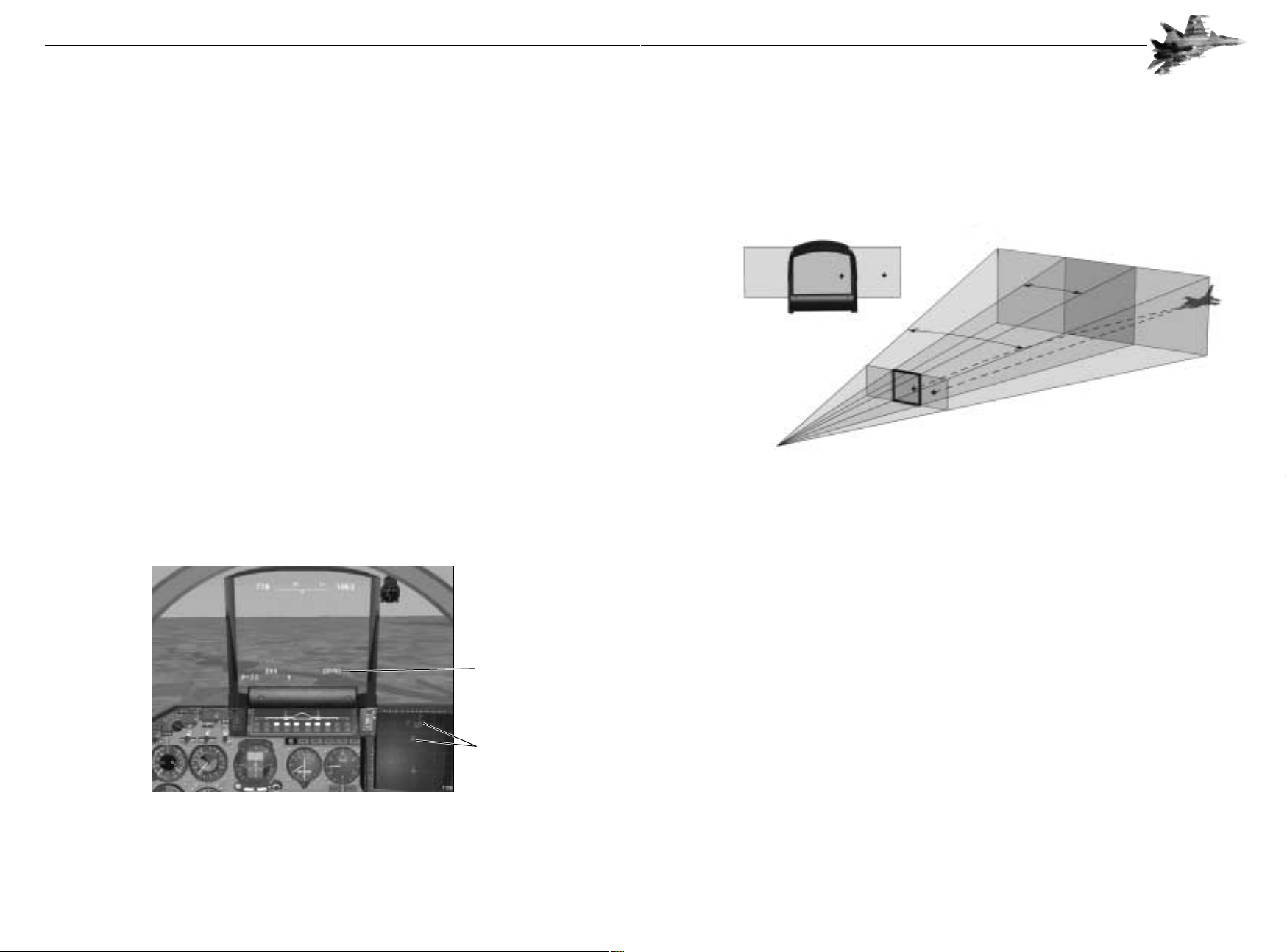
HUD Scaling Considerations
Keep in mind that the scan zone for sub modes is larger than the area covered by the HUD.
Targets are therefore “scaled” to fit the dimensions of the HUD. The target marker in the HUD,
consequently, points toward the target but is not an accurate indicator of the target’s azimuth and
elevation. The gimbal markers on the MFD will give you a better idea as to how close the gimbal
limit for the target is and you will easily interpret off boresight angle.
4-8b: Target Positions are Scaled to Fit the HUD
Acquiring A Target in LD< (BVR) Mode Step-by-Step
Let’s walk through the process of acquiring a BVR target.
Step 1. Switch to BVR Mode
Press the 2 key and check that the HUD Mode Indicator shows the notation of the LD< – J<P
(BVR - SCAN). If there is a friendly AWACS aircraft airborne J<P (SCAN) will be replaced by
LHKJ (AWACS). Use the + and – keys to adjust the range displayed on the MFD and the HUD.
If you have an AWACS datalink, then you will almost immediately receive contact data on the MFD:
Friend or foe, distance, and aspect angle. (See above for more on AWACS). If this is the case, you
can cycle through the contacts on your MFD by selecting the (~) key. Then go to step 5.
Step 2. Select a sensor.
Activate the radar or EOS. The notation at the left of the HUD should read B (I) or N (T) for the
radar and EOS, respectively. Alternatively, the HUD will display LHKJ (AWACS) if a friendly
AWACS aircraft is airborne and in range.
Step 3. Direct Scan Zone
Using the Shift - coolie hat on your joystick or the scan zone control keys, aim the scan cone in the
portion of airspace you wish to scan. The HUD will immediately show detected contacts, if any.
CHAPTER 4: Air-to-Air Combat 55
When tracking a target in Attack Mode, manoeuvre your aircraft so that the Aiming Reticle stays
close to the HUD centre datum. This eases your work load when the target is not very visible and
prevents the target from breaking the lock. Remember, if you use the EOS, the flashing of the Shoot
Cue with a frequency of 1 Hz warns you that the system is not measuring the range to the target.
Keep in mind that for SARH missiles, it is necessary to illuminate the target for the entire flight
time of the missile. After launch this will be represented by the A (Auto-track) cue flashing at 1
Mz. So know your missiles!
If the target leaves the tracking area, or you break the lock by pressing the Tab key, or the target is
destroyed, the radar (the EOS) returns to the submode which preceded the Auto-track. Similarly, if
the radar or EOS is damaged or you switch sensors off, the lock breaks and the radar returns to
the submode which proceeded the Auto-track.
LD< – LHKJ (AWACS) AWACS Datalink
The Flanker’s ability to datalink with AWACS aircraft allows pilots to locate, stalk, and engage targets without ever engaging onboard sensors. This form of “stealth” lets the Flanker close on its
prey without betraying its presence. A friendly AWACS aircraft (an A-50 or E-3) must be airborne
simultaneously to your aircraft. The datalink information can be viewed on the MFD in all combat
modes as well as the NAV modes, however, these contacts can only be selected for targeting
from the BVR mode, with the radar and the EOS off. While in BVR mode, if there is a friendly
AWACS aircraft airborne, a datalink will be established and contacts detected by the AWACS will
appear on the MFD as standard aircraft symbols (friendly and enemy). The AWACS contacts will
appear more subdued (less bright) than regular contacts. While in BVR mode you can use the ~
Key to cycle through AWACS contacts on the MFD. A selected contact will appear brighter. Use
the Tab Key to lock up a selected AWACS target in Auto-track. Once you hit the Tab Key your
radar will illuminate the target and you will no longer be passive.
4-8a3: LHKJ (AWACS) Submode
FLANKER 2.0
FLANKER 2.0
54 CHAPTER 4: Air-to-Air Combat
AWAC’s Datalink
Active
Contacts
Page 30
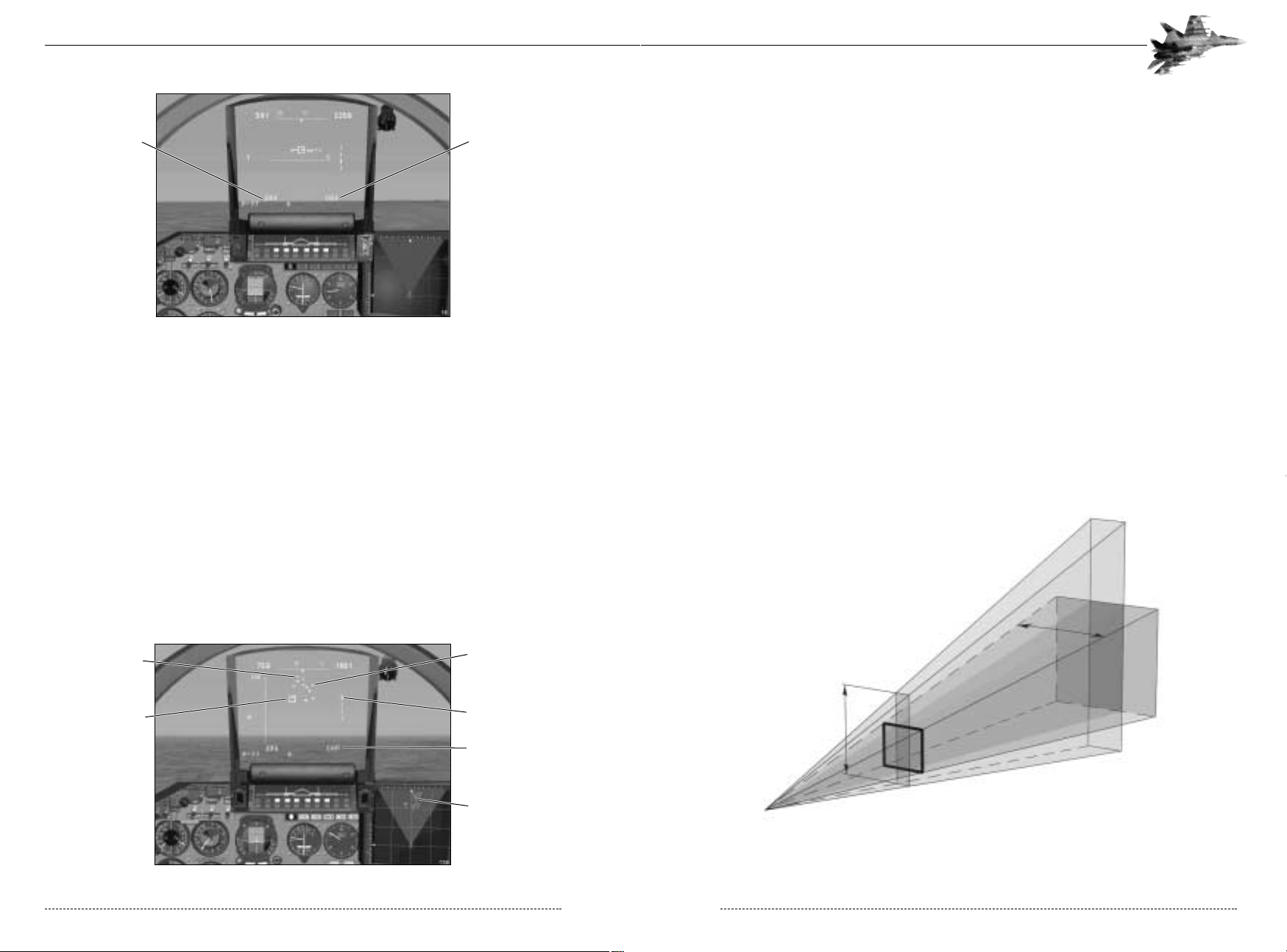
Step5. Lock onto the target
To lock onto the selected TWS contact, press the Tab Key. If the lock parameters are met (aspect
angle, Radar Cross Section, distance, speed, etc.), the radar (or the EOS) switches to Attack
Mode. The Autotrack Cue (A) appears above the Radar Cue or the EOS Cue.
To lock onto a target if you have an AWACS datalink, select the Tab key.
It is recommend that you lock onto a target at a range that is close to a reliable range of the
selected air-to-air missile. It gives the target less warning that it has been locked on and therefore
increases your probability of scoring a fast kill.
On the MFD the locked target will be illustrated by a solid triangle symbol, the target aircraft is
now being illuminated by a 2.5∞ radar beam.
Step 6. Select Air-to-Air Missile and Launch
Select the appropriate air-to-air missile for the range and type of target by pressing the D Key.
Consider range, manoeuvreability, size, and speed of the target. Once the target is within the
launch parameters of the weapon and the launch cue is displayed in the center of the HUD, your
are authorized to fire the weapon.
<D< /Close Air Combat Mode
The <D< (CAC) Close Air Combat mode is used for attacking targets which you have spotted
visually or which are known to be within close range (less than 25 km). The radar (the EOS) locks
onto a target in an area limited by the angular dimensions of the HUD, namely 20°x20° (±10° in
azimuth and ±10° in elevation). The IKTV (HMTD) submode permits the pilot to acquire targets with greater off boresight angles.
4-10c: The <D< Scan Cone
CHAPTER 4: Air-to-Air Combat 57
4-9: The J<P (SCAN) Submode Symbology
Step 4. Assigning Contacts to Track While Scan mode
To select a particular target, steer the HUD Target Designator Box (HTD Box) onto the contact of
interest and press the Tab key. The contact will switch from being scanned to tracked. This
method is called “manual selection” since you are selecting an individual contact to be tracked by
the radar. The Weapons Control System also offer an automatic contact analysis routine whereby
contacts with the highest closure speed/distance ration will become tracked contacts.
To automatically designate multiple scan contacts to the Track While Scan mode press the 2 key
when there are multiple scan contacts displayed on the HUD while you are in J<P (SCAN)
mode. Up to 8 of the scan contacts will now be designated as track contacts and will now be
displayed on the MFD.
To remove an individual contact from Track While Scan mode and place it back to scan, place the
HTD Box on the triangle symbol on the HUD and press the Ctrl-Tab Key. The contact will be
removed from the MFD and the triangle symbol will become a dash symbol on the HUD.
To remove all TWS contacts from the MFD and return to Scan mode press the 2 Key again and
restart the sequence.
4-8a2: The CYG (TWS) Submode Symbology
FLANKER 2.0
FLANKER 2.0
56 CHAPTER 4: Air-to-Air Combat
Track and Lock
Sub Mode Selected
BVR Mode Selected
Scanned Contacts
Range Bar
Tracked Contacts
Track While Scan Sub Mode
Tracked Contacts
Selected Contact
Page 31

4-10b: The Radar Bore Site Mode Close Air Combat Symbology
Acquiring A Target
To acquire a target at close ranges, proceed as follows.
Step 1. Switch to CAC Mode
Press the either 3 or 4 to select the desired appropriate <D< (CAC) submode. Make sure that the
HUD Mode Indicator shows the <D< (CAC) notation.
Step 2. Select a target
Once you have visually spotted a target, place it in the field of view of the HUD by manoeuvreing
your aircraft and/or Vertical Scan or Boresight scan cones.
4-11: Moving the Scan Cone to the Target
Step 3. Lock onto the target
To lock onto the target, press Tab. Failing locking conditions, the Autotrack Cue flashes at a frequency of 2 Hz. In this case press Tab until A turns permanent. The radar/EOS switches to
Autotrack Mode as evidenced by the change of information on the HUD and MFD. If several targets are within the field of view of the HUD, the equipment tracks the target that has been detected earliest. You may have to press Tab several times to obtain a lock.
CHAPTER 4: Air-to-Air Combat 59
<D<-BC (VS) Vertical Scan Submode
The first sub mode, called Vertical Scan submode and is depicted on the HUD by a narrow vertical
band. This submode can be selected by pressing the 3 key. It is designed to acquire targets in a
dogfight. Both radar and EOS are active, but this mode is very stealthy as the radar is not constantly emitting. It is “primed” and ready in a stand-by mode ready to send a very stong and fast
scan along the 25∞/60∞ Vertical Scan cone. The HUD will display a P (which is the Russian R) on
the left side of the HUD to denote “ready” or standby as well as the T for the EOS. Any contact
detected and designated (locked) within the cone will immediately stop the scan process and
focus a 2.5∞ circular beam on the target switching the submode to Attack (ATK).
Manoeuvre your aircraft so as to position the visually acquired target within the limits of the
Vertical Scan Bar portrayed in the center of the HUD. The actual scan cone extends 20∞ above
and behind the HUD. This means that you can lock a target even if you position it within that
imaginary extended band. You can also steer the Vertical Scan cone (band) left and right 10∞ by
using the target designator key commands.
4-10a: The Vertical Scan Mode Close Air Combat Symbology
<D<-CNH (BORE) Boresight Submode
The second sub-mode, entitled Radar Bore Site scans in a narrow 2.5∞ circular beam, which can
be steered up, down, left, and right (using the target designator controls) within the angular limits
of the HUD, 20∞ x 20∞. This mode is used to focus the radar on a specific target, and is especially useful in crowded airspace. Activate the CNH (BORE) submode by pressing the 4 key. By
steering the beam directly to the desired target, you reduce the risk of accidentally locking the
wrong target. Similar to the Vertical Scan submode, the radar is not illuminating continuously but is
on standby and primed to send out a strong circular pulse to the target. If the radar receives a
return pulse the system switches immediately to Attack mode.
FLANKER 2.0
FLANKER 2.0
58 CHAPTER 4: Air-to-Air Combat
EOS Cue Band Mode Selected
Close Air Combat
Mode Selected
Selected Weapon Type
Close Air Combat
Mode Selected
Circle Sub Mode
Selected
Boresight Sub Mode
Page 32
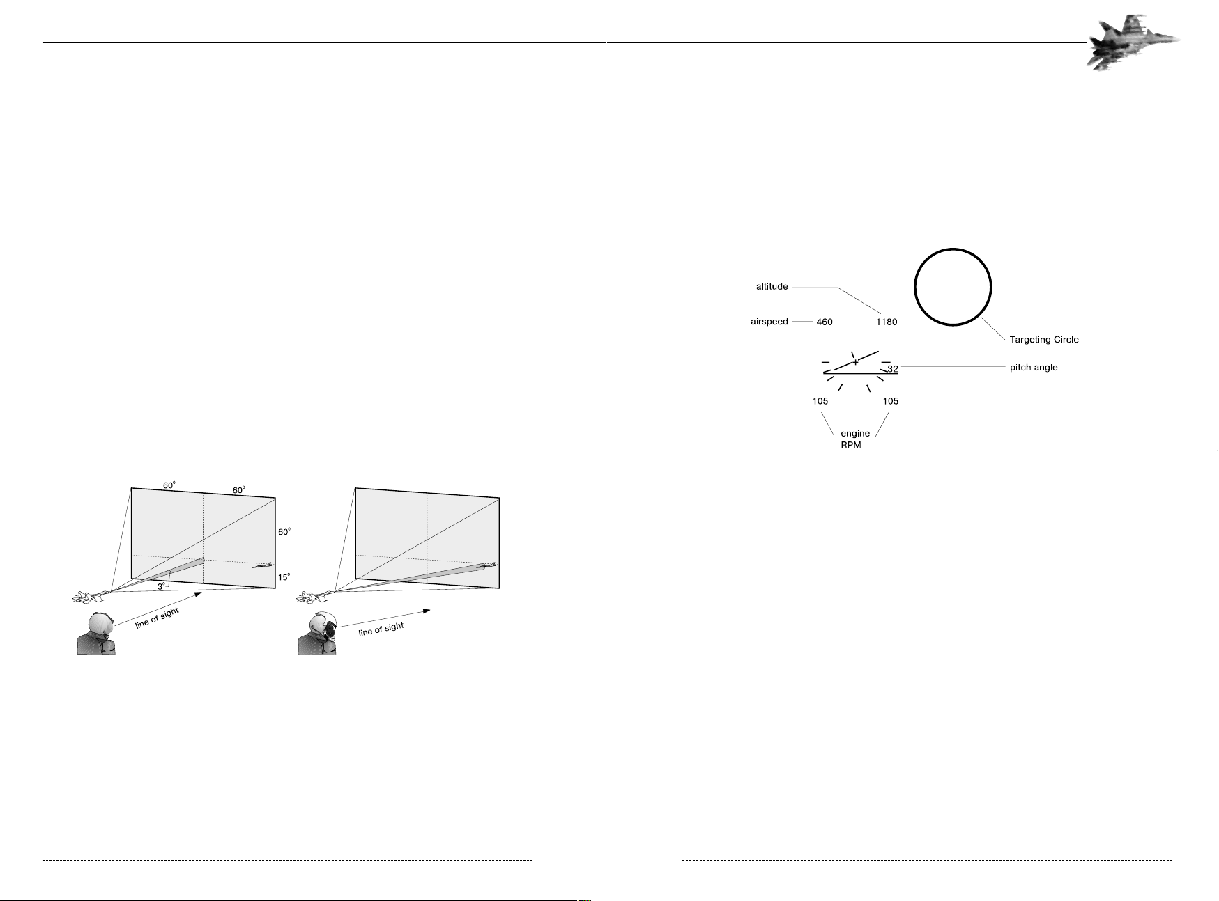
Step 3. Lock onto the target.
To place the HMTD onto the padlocked target, use either the joystick coolie hat or the scan cone
keys. Once the circle is on the target press the Tab key. They HMTD is now padlocked to the target (along with your eyes) and the Weapons Control System is put into the Auto-track mode.
If the HUD gets out of view, a set of visual cues appears next to the Targeting Circle. These cues
indicate your airspeed and altitude, the aircraft datum and pitch angle, and the engines RPMs
(105% for both engines in the figure below).
Caption 4-14: Visual Steering Cues with the Helmet Mounted Sight
ABJ /Longitudinal Missile Aiming Mode
Should the radar or the EOS be damaged, you can still use the direct targeting capability of missiles
fitted with IR or active radar seeker heads. This requires placing the target into the seeker’s field of
vision and locking on. The seeker tracks the target in an area limited by its gimbal limits and by the
tracking range. The latter depends on the type of missile, type of target, and attack geometry.
Longitudinal Missile Aiming
You use the ABJ (LMA) Mode for attacking a visible airborne target in a dogfight, by selecting
the 6 key. The missile seeker locks onto the target in an area limited by the angular dimensions of
the seeker’s field of vision (about 3°), which is aligned along the longitudinal axis of the aircraft.
The seeker head locks onto the target within 2-3 seconds.
To lock onto a target in ABJ (LMA) Mode, perform the following steps:
Step 1. Switch to Longitudinal Missile Aiming Mode
To do this, press the 6 key. If the selected missile has a seeker head of an appropriate type, the
HUD shows the fixed Aiming Reticle (3°) and the seeker aligns itself along the longitudinal axis of
the aircraft. The Weapon Readiness Panel shows the selected missiles.
CHAPTER 4: Air-to-Air Combat 61
IKTV (HMTD) Helmet Mode
This is also a Close Air submode that, while visually similar to the Boresight submode, is very
different. This sub-mode can be activated by selecting the 5 key. The Helmet-Mounted Target
Designation (HMTD) system frees the pilot from having to boresight his enemy by slaving the
radar and the EOS to the helmet-mounted sight. Once you have acquired the target, the Helmet
Mode allows you to keep your eye on the target at all times by turning your head in the direction
of the target’s motion. The real world system works by using a pair of head position sensors on
the cockpit panel, on each side of the HUD.
The radar (the EOS) locks onto the target in an area limited by the 2.5∞ scan cone. The pilot
should keep the cone within the limits of the radar/EOS field of search. That means that you
cannot use your helmet-mounted sight to acquire and lock onto targets beyond the gimbal limits
of the radar antenna or the IRST sensor ball.
Acquiring a Target
Use the following procedure to lock a target with the IKTV (HMTD) mode:
Step 1. Switch to Helmet Mode
Press the 5 key. The HUD submode Indicator displays the notation IKTV (HMTD) (pronounced
‘shlem’, denotes ‘HELMET’ in Russian) on the lower right corner of the HUD. The Targeting Circle
appears in front of you and follows the movement of your head.
Step 2. Select a target
Caption 4-13: Steering the Scan Pattern with the Helmet Mounted Sight
Once you have visually spotted a target, place it within the Targeting Circle by manoeuvreing the
aircraft and turning your head in the direction of the target. You can move your head using the joystick coolie hat or the numeric keys on the keypad. In so doing, the Targeting Circle moves with
you head. The figure above illustrates how you search for a target when the EOS is slaved to the
HMTD system. To padlock your eyes onto the target, press * (asterisk) on the keypad.
FLANKER 2.0
FLANKER 2.0
60 CHAPTER 4: Air-to-Air Combat
Page 33
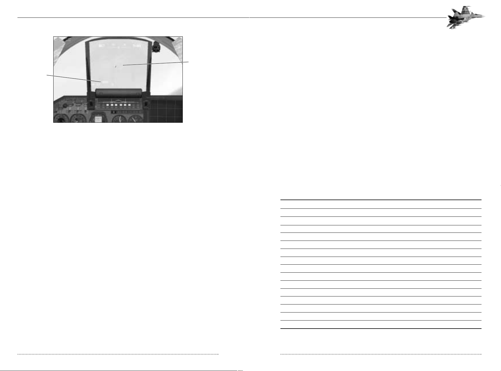
Using the GSh-301 Cannon
Regardless of the combat mode selected, (BVR, CAC, LMA, or Helmet), you can enable your
GSh-301 cannon at any time by pressing the C key. Depending on whether or not the radar
(EOS) has been locked onto the target, the gunnery with the cannon can be performed:
• with targeting from the radar or the EOS
• without assistance from the radar or the EOS.
For more information on using the cannon, refer to the “Weapons” chapter.
AIR-TO-GROUND COMBAT
The Su-27, is primarily an interceptor The carrier-based Su-33, however, is designed as a multirole, aircraft.
• Ground target work may be conventionally divided into the following steps: search, identify, and
attack. If a target you are searching for cannot be spotted visually, use your radar, which helps to
acquire targets at long ranges and where appropriate download the target coordinates into the
Weapons Control System (WCS). The appropriate aircraft bomb and missile payload depends
very much on the type of mission planned and expected targets. For information on using air-toground weapons, see the “Weapons” chapter.
To switch the onboard systems to Air-to-Ground (A2G) Mode, you should press the 7 key and
check that the HUD Mode Indicator reads PTVKZ (Russian designation for GROUND, pronounced ‘zem-lja’). To control your weapons and onboard systems in A2G Mode, you use nearly
the same keys as in the air-to-air modes:
KEY ACTION
I Toggle radar
O Toggle TV Seeker On/Off (if TV guided missile is present)
`
Select next assigned target on MFD
Tab Lock on/off target
; (Semicolon) Move radar/TV scan zone DOWN
, (Comma) Move radar/TV scan zone LEFT
. (Period) Move radar/TV scan zone UP
/ (Slash) Move radar/TV scan zone RIGHT
Ctrl+I Center radar antenna/IRST ball
- (Minus) MFD zoom in
+ MFD zoom out
D Cycle through weapons
C Activate/deactivate cannon
Ctrl+V Toggle Salvo mode
Ctrl+W Jettison all weapons
Spacebar Fire current weapon
*Note that selecting the cannon temporarily disables all other ground weapons systems and targeting.
CHAPTER 4: Air-to-Ground Combat 63
Caption 4-18: Longitudinal Aiming Mode Symbology
Step 2. Select a target
Once you have visually spotted a target, place it within the Aiming Reticle by manoeuvreing
your aircraft.
Step 3. Lock onto the target
Enter targeting data into the seeker head by pressing the Tab key. If the locking conditions are
met, the seeker locks onto the target and starts tracking it. We’ll describe the Seeker Track Mode
in a separate section below.
Seeker Track Mode
After a missile seeker has locked onto the target, it switches to track mode continuously keeping
the target within the seeker’s field of view. The dimensions of the single target tracking area
depend on the type of missile and are limited by the gimbal limits of the seeker head and sensor
sensitivity. Gimbal limits may range from 20° (the R-60 Aphid) to 80° (the R-77 Adder). Tracking
range depends on type of target and specifications of the seeker head and may vary between
5 km and 30 km.
When the seeker tracks a target the HUD shows the following information: altitude and true airspeed of your aircraft, aircraft datum and bank scale, type of missile and quantity. The HUD Mode
Indicator displays ABJ (LMA). Lock onto the target is evidenced by the movable Aiming Reticle
showing an angular position of the seeker head and by the Shoot Cue GH.
You should manoeuvre the aircraft so that the movable Aiming Reticle stays close to the HUD
center datum. This eases aiming at the target and prevents the target from breaking the lock.
If the target leaves the tracking area of the seeker head, or you break the lock by pressing Tab, or
the target is destroyed, the HUD returns to the mode which immediately preceded the track mode
ABJ (LMA).
FLANKER 2.0
FLANKER 2.0
62 CHAPTER 4: Air-to-Air Combat
Mode Indicator
Aiming Reticle
Page 34
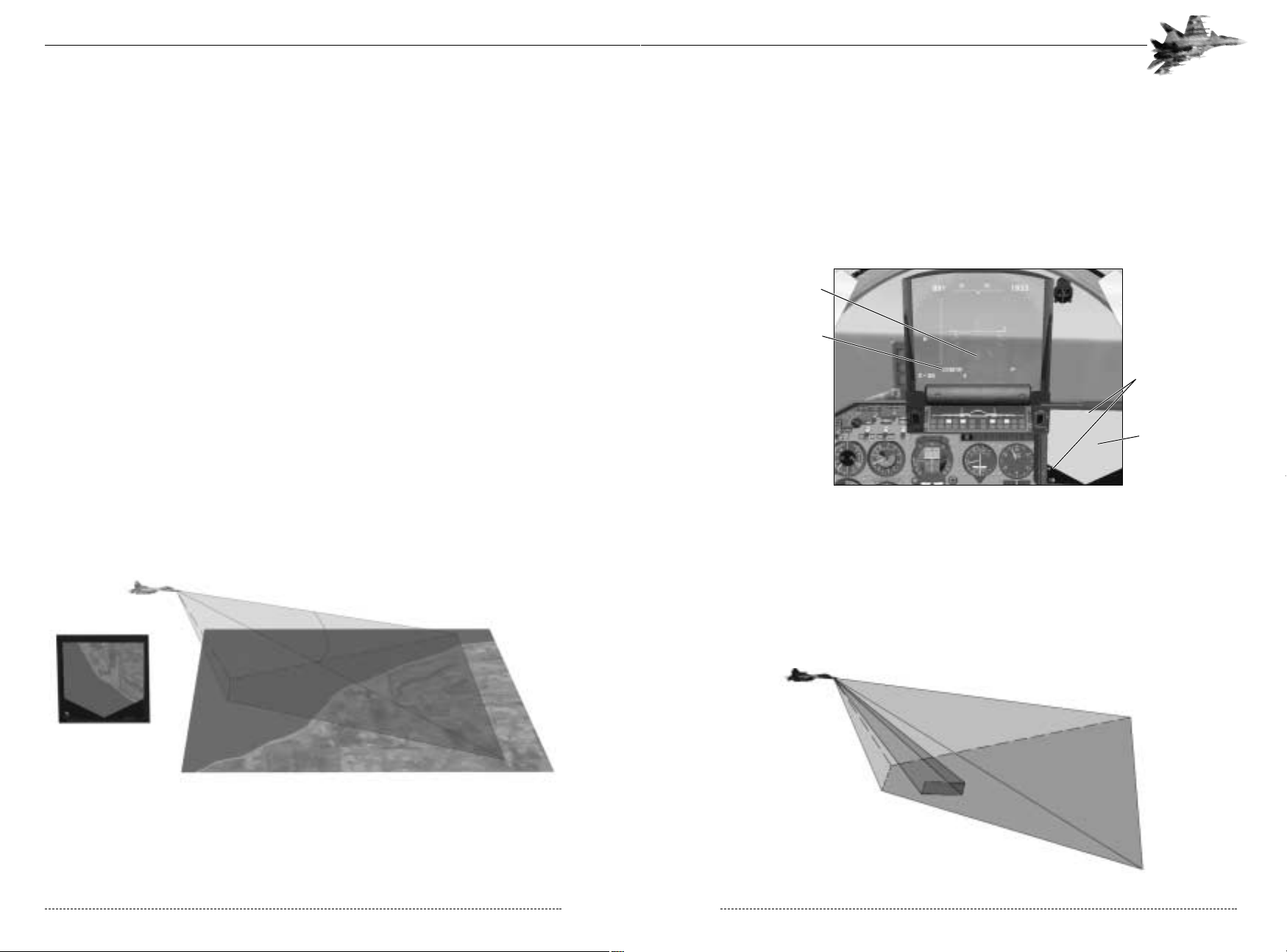
The MFD processes radar information into a synthesized image of the terrain as if you were looking at the ground map from above. Two V-shaped indexes, one to the left and another at the top
of the MFD, show the position of the scan zone center with respect to the aircraft’s longitudinal
axis. Distance to the center of the scan zone in kilometers is shown in the lower left-hand corner
of the MFD. You can move the scan zone center farther or nearer with the coolie hat on your joystick or with the vertical radar/TV scan zone control keys Period (.) and Semicolon (;).
The diamond-shaped Radar Target Designator on the HUD represents the direction of the scan
zone center. If the Radar Target Designator goes beyond the limits of the HUD, the diamond is
overlapped by the ‘X’ symbol and stays near the edge of the HUD.
4-23: The Scan Mode Symbology
After you have selected an area of interest using information shown on the MFD, you can narrow
your search by switching the radar to Search in Wide Area (SWA). To do this, press the + key.
Search in Wide Area (SWA)
Pressing the + key in scan mode focuses the surface mapping mode on a smaller area, magnifying
the view 20 times.. In the SWA Mode the radar scan zone has angular dimensions of about
10°x10° and moves with the aircraft.
CHAPTER 4: Air-to-Ground Combat 65
PTVKZ (GRND) Air-to-Ground Mode
In A2G Mode the Miech-33 radar scans ground surface within the limits of its field of search of
angular dimensions of 120°x120° in a range of 3-150 km. The maximum size of the scan zone along
the flight path is limited both by the maximum deflection angle of the radar antenna (60°) and by its
inclination angle with respect to the horizon (3°). Linear dimensions of the field of search depend
on your altitude - the lower you fly, the smaller the dimensions of the field of search.
The A2G mode offers three different scan patterns designed to scan different size areas at varying
degrees of resolution. These three scan patterns cycle from a broad, low-resolution search beam
to a highly-focused, high-resolution pattern. Use the + and - keys to switch between resolutions.
When you activate the radar in A2G Mode (the I key), the B Radar Cue and the Radar Designator
diamond appears on the HUD. The radar starts operating in a Scan Mode.
MFD
If the radar is not active, the MFD shows a navigation display, similar to the one used by the
VFHI (ENR) navigation mode. Besides waypoint and flight path markers, predesignated targets
are also displayed. Use the ` key to cycle through the targets. Once the radar is activated, the
MFD displays a radar-generated map. The following sections describe the details of the MFD
ground radar display for each submode.
Scan Submode
This mode provides for coarse mapping of the terrain laying dead ahead. In the Scan Mode the
60∞ scan cone can be controlled by orienting the radar antenna (the scan cone) in the vertical
plane +/- 30∞ and in the horizontal +/- 30∞. The antenna is stabilized in roll and pitch. However
as your heading changes, the scan zone moves so that its center is always lined up with the aircraft’s longitudinal axis.
4-22: The Scan Mode Search Pattern
FLANKER 2.0
FLANKER 2.0
64 CHAPTER 4: Air-to-Ground Combat
4-24: The SWA Search Pattern Within the Total Scannable Area
Diamond Indicates Where
Radar is Looking
Ground Attack
Mode Selected
Scan Mode’s
Map Display
Antenna Position
Indicators
Page 35

4-27: The SNA Symbology
The MFD shows a synthesized image of the terrain with cross-hairs in the center of the search
area. Using information on the MFD, you select a target (building, bridge, vehicle, etc.) by placing
the cross-hairs on the target with the joystick coolie hat or the radar/TV scan zone control keys.
You can also target visually by superimposing the Radar Target Designator on a target of interest.
Thus, the diamond in the SNA Mode always points to the designated target.
Once you have placed the cross-hairs on the target, lock the position by pressing the TAB key.
You can break the lock by pressing the TAB key a second time.
CHAPTER 4: Air-to-Ground Combat 67
Information on the HUD is similar to that of the Scan Mode. The MFD shows an enlarged synthesized image of the terrain with the Narrow Search Area (NSA) frame (see below) in the center.
Again, the number in the lower left-hand corner of the MFD shows distance to the center of the
scan zone. (center of the NSA frame).
4-25: The SWA Symbology
You can control the position of the scan zone center as to angles in vertical and horizontal planes
with the radar/TV scan zone control keys. Once you have placed the NSA frame on your desired
search area, switch the radar to Search in Narrow Area (SNA) Mode by pressing the + key again.
You may return to Scan mode by pressing the – key.
Search in Narrow Area (SNA)
SNA is the most focused, detailed ground mapping mode, magnifying the display 64 times and is
used to locate and lock ground targets. In the SNA Mode the angular dimensions of the scan
zone are 3°x 3. You control the scan zone in much the same way as in SWA Mode, however, the
scan zone center does not move with movements of the aircraft, since the radar tracks a certain
point on the ground or water surface.
The SNA Mode refers the position of your aircraft to the selected coordinates on the ground. Even
if the line of sight to the selected point moves beyond the field of search, the radar will resume
tracking that point as soon as this becomes possible. Locking on a point provides accurate target
designation for anti-ship missiles and facilitates sighting for other types of ASMs, bombs and
unguided rockets in conditions of poor visibility or at night.
FLANKER 2.0
FLANKER 2.0
66 CHAPTER 4: Air-to-Ground Combat
Ground Map Magnified
20 Times
Target Object
SNA Frame
Diamond Indicates
Radar’s Focus
Map Magnified
64 Times
Target Object
Movable Targeting
Cross-hair
Page 36

CHAPTER 5: Ground School 69
If you have no flight simulator expertise or if you have any difficulties piloting the Flanker, this
chapter is just what you need. In this chapter we’ll not take too close a look at the theory of flight,
but we shall give you the minimum of information necessary to understand the terminology and
the description of techniques and nuances of piloting.Though we do not have intentions to prepare you for demonstration flights during exhibitions in Le Bourge, in this chapter we do explain
how to execute some aerobatics on the Su-27. Here you can obtain further insight into the
delights of a realistic flight simulation and will be able to feel yourself not only as a first-rate hunter,
but as a real jet jockey. The Su-27 lets you work wonders in the air. You will see it yourself when
you manage to do such famous aerobatics manoeuvres as the “tail slide” and “Pugachev’s Cobra”.
The latter manoeuvre not only has aesthetic value, but can also be effectively used in air combat.
Primary Forces and Angles
Figure 5-1: The Four Forces of Flight
You’ve probably read all about the four forces of flight: lift, drag, thrust, and weight, as illustrated in
Figure 5-1. Working within the limitations imposed by these forces, the pilot manoeuvres the aircraft through space by manipulating pitch, roll, and yaw. Figure 5-2 illustrates these three motions
and the angles used to measure them.
CHAPTER 5
Ground School
CHAPTER 5
Ground School
Defense Visual Information Center - Department of Defense
Page 37
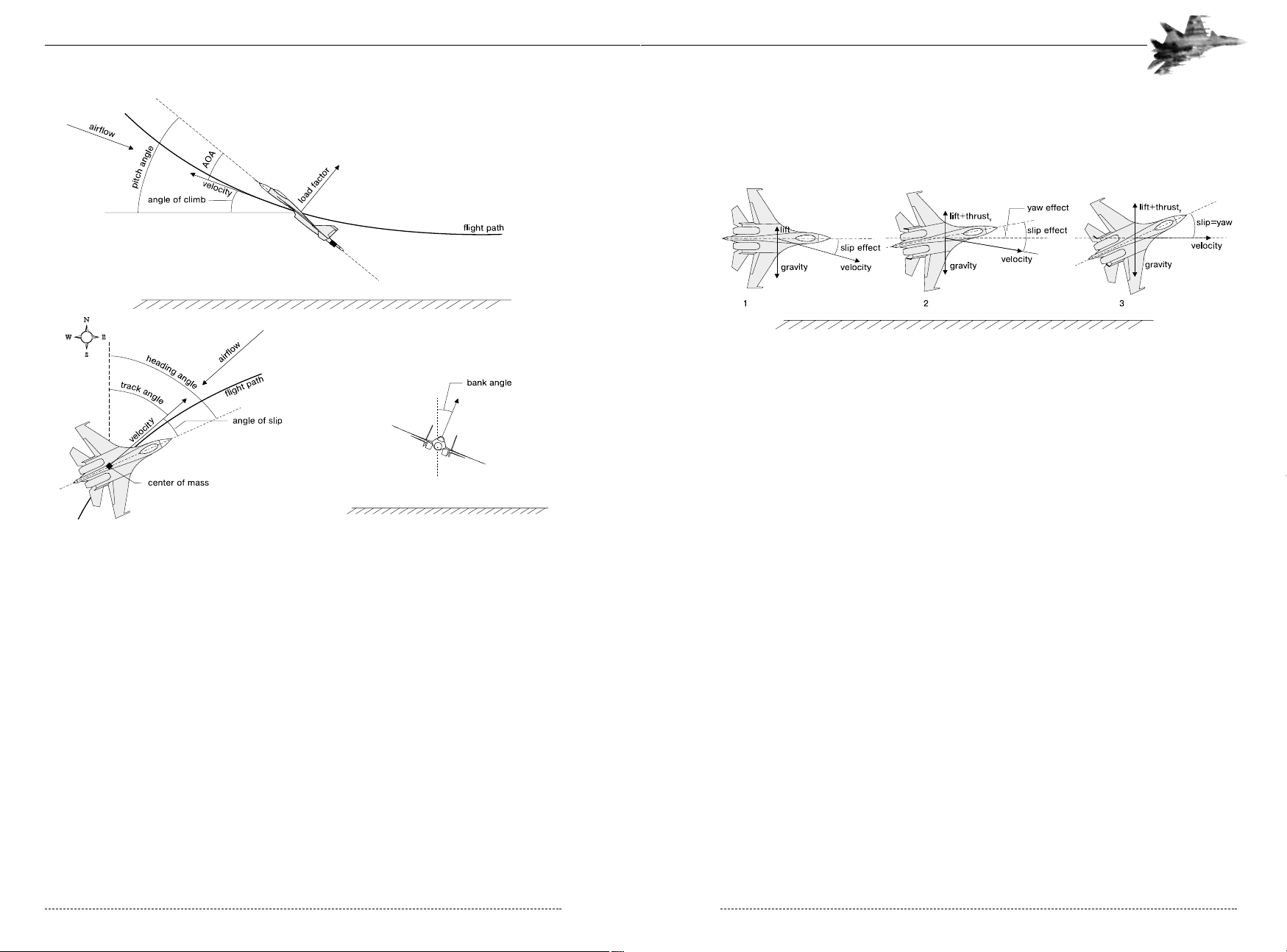
Slip angle is another important angle describing aircraft motion. This angle characterizes the asymmetry of airflow passing over the aircraft. This angle sometimes may coincide with the yaw angle.
The difference between these two angles is illustrated in the figure below.
Figure 5-3: Slip Angle
All three aircraft are flying in the vertical plane in knife edge. Aircraft 1 is sideslipping towards the
ground since the gravity force is greater than lift. The pilot in Aircraft 2 applied some left rudder so
that the vertical component of thrust is added to lift and the aircraft develops yaw. Here the aircraft is still going towards the ground but slower. The pilot of Aircraft 3 deflected the rudders farther so that the aircraft is moving straight and level (the gravity is fully compensated by thrust and
lift). In the third case the slip effect coincides with the yaw effect.
The Edge of the Envelope
A combat pilot, simulated or otherwise, does not whip out a slide rule during a dogfight and calculate the variables influencing the outcome. The pilot, does, however, need to understand the
basic principals which dictate the flight envelope and what actions on his part will improve or
degrade flight performance.
Angle of Attack and Stalls
As explained earlier, angle of attack (AOA) represents the difference between where the aircraft is
pointed and where it’s actually going, and is largely the result of momentum. AOA increases anytime the pilot pitches the aircraft, including when initiating a climb or dive. Moving the control surfaces causes the aircraft to rotate about its pitch axis and point in a new direction. Momentum
keeps the aircraft moving along its original heading until the thrust from the engines and lift can
push the aircraft in the new direction. Decreasing engine power during level flight also increases
AOA. As the aircraft slows, it generates less lift and gravity begins to pull it down while the nose
remains pointed near the horizon.
AOA and airspeed impact the amount of lift (g load) generated by the wings. Generally speaking,
if the wing isn’t stalled, then increasing AOA will increase the amount of lift being generated.
Likewise, increasing speed while holding a constant AOA will also increase lift.
CHAPTER 5: Ground School 71
Figure 5-2: Pitch, Yaw, and Roll
To describe these various angles, it is more convenient to use the vector of velocity rather than
direction of air flow as a frame of reference. The velocity of the aircraft is always opposite to the
direction of the air flow and equal to it in the absolute value. The flight path is a trajectory of
motion of the aircraft’s center of mass, that is the point where all the forces acting upon the aircraft are applied. As you can see, the direction of motion at any particular moment doesn’t always
coincide with the aircraft’s longitudinal axis.
The angle of attack (AOA) is the angle between the aircraft’s longitudinal axis and the direction of
its motion, i.e. the velocity vector. Up to a certain degree, the greater the AOA, the greater the lift
and drag, and hence the increase in thrust required to maintain a constant speed. If the aircraft
flies at a high AOA, the airflow cannot conform to the upper surface of the wing and forms turbulent vortices. The wing starts to lose its performance, maybe resulting in a dangerous stall or spin
and, probably, in a catastrophe.
The pitch angle measures the angle between the horizon and the aircraft’s longitudinal axis. Note
that pitch angle is not the same as the angle of climb which indicates the angle between the air
flow (or velocity vector) and the horizon. This angle is also called flight path angle, which when
added together with the AOA constitute the pitch angle. Therefore, in level flight the angle of climb
or flight path angle is equal to zero.
FLANKER 2.0
FLANKER 2.0
70 CHAPTER 5: Ground School
Page 38
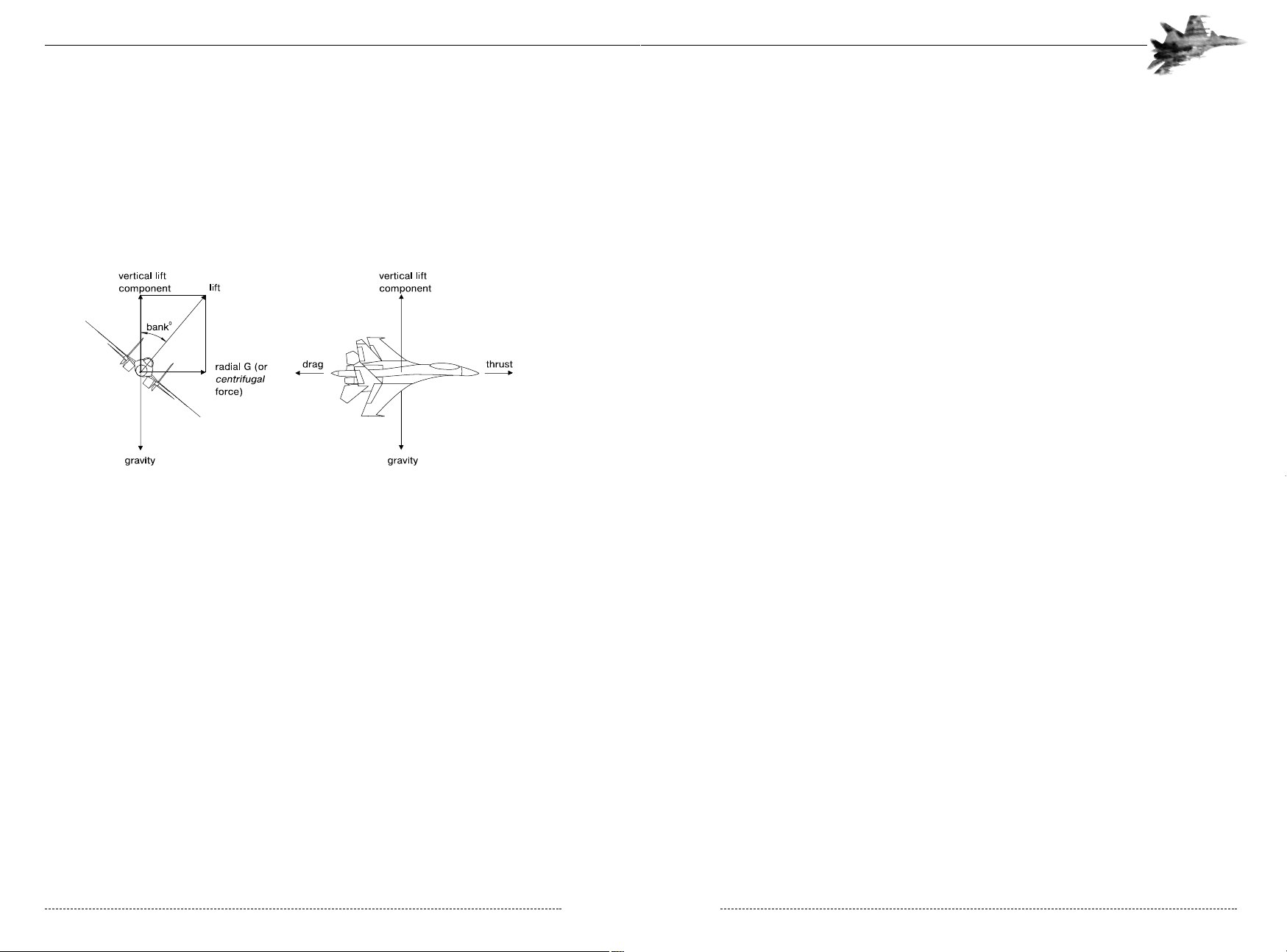
Airspeed, meanwhile, is a two-edged sword. For a given AOA, increasing airspeed increases the
amount of g-load being generated. That helps turn performance. Unfortunately, as we see from
the turn rate and turn radius equations, increasing airspeed actually decreases turn performance.
Further, keep in mind that lift is a “bounded” quantity; the pilot and airplane can only handle so
much g-load before blacking out or breaking, respectively. We can see from the equations that
pulling 8g at 1000 km/hr will result in worse turn performance than pulling 8g at only 750 km/hr.
Increases in speed while g-load remains constant can only hurt turn performance.
Energy Management
This brings us to the topic of energy management. No pilot whips out a slide rule during battle to
calculate turn performance. Instead, the pilot relies on an understanding of the concepts presented here and how to utilize them in the real world. In other words, the pilot learns to manage the
aircraft’s energy by applying the principles discussed thus far.
What is Energy?
So, what exactly do we mean by “energy,” anyway? By and large, “energy” refers to either airspeed (kinetic energy) or the ability to increase airspeed by diving from a higher altitude (potential
energy). Despite the fact that airspeed degrades turn performance, we have to have sufficient airspeed to generate g-load. The goal, therefore, of energy management has two parts. First, we
want to have enough airspeed available to generate the desired amount of g-load when we need
it. Second, we want to keep airspeed to the bare minimum needed to achieve that desired g-load.
Instantaneous and Sustained Performance
The question, of course, is how exactly does one manage energy? Try thinking of energy as the
“money” that the aircraft uses to “buy” manoeuvres. Like most of us, the aircraft has a very limited
budget. Through careful allocation of funds, we can buy the staples we need as well as an occasional large item, like a car or television set. Carelessly spending funds with little forethought usually leaves us broke just when we need money the worst. We’ll now examine the types of energy
the aircraft has to spend and the various ways to distribute it.
The aircraft has two main sources of energy. Airspeed, or kinetic energy represents “cash” in our
money analogy. Manoeuvreing requires speed, which comes primarily from the engines’ thrust.
Altitude, or potential energy, can be quickly converted to additional airspeed by diving.
When it comes to “spending” that energy, we talk about Instantaneous and Sustained performance. Instantaneous performance refers to the maximum turn performance the aircraft is capable
of, usually at the maximum g-load available. It only lasts for a brief moment, though, as high gloads generate substantial drag, which quickly slows the aircraft. Sustained performance refers to
the “steady state” performance of the aircraft when engine thrust reaches equilibrium with drag.
Sustained performance will be well below the instantaneous performance; theoretically, the aircraft
could maintain this steady state until it runs out of fuel.
CHAPTER 5: Ground School 73
Increasing AOA too much, though, will disrupt the airflow over the wing and reduce the amount of
lift being generated. This is called a stall. A stall can occur at any altitude, airspeed, and flight attitude. An aircraft travelling at 1000 km/hr will stall if the pilot exceeds critical AOA. The pilot wants
to maximize the amount of lift being generated, and subsequently tries to increase AOA. Pushing
just a fraction too far, though, stalls the wing and greatly decreases lift.
Lift, Turn Rate, and Turn Radius
The lift vector (the direction of the generated g load) is perpendicular to the wings. Banking the
aircraft, as shown in figure 5-3, reduces the amount of lift directly opposing gravity.
Figure 5-4: How bank angle affects g-load
Turn performance is generally described in terms of turn rate and turn radius, both of which are
dependent upon the aircraft’s speed and the amount of lift, or g-load, being produced. Turn rate
measures the speed at which the nose is moving around the circle, typically measured in degrees
per second. A high turn rate, therefore, means the aircraft could complete a 360-degree turn very
quickly. Turn radius, as the name implies, measures the size of the aircraft’s turn. The ideal fighter
would have a very high turn rate coupled with a very small turn radius.
Turn rate is largely determined by g-load divided by airspeed. A high g-load increases turn rate
while a high airspeed decreases it. Turn radius is primarily determined by airspeed squared divided by g-load.
Therefore, increasing airspeed quickly increases the turn radius while increasing g-load reduces
turn radius.
Putting It All Together
We can now see how all the pieces fit together. Increasing the AOA increases the amount of lift
being generated until the wing finally stalls. Increasing the g-load, meanwhile, improves both turn
rate and turn radius. Unfortunately, increasing AOA also increases drag, and slows the aircraft
down. This in turn reduces the g-load available and decreases turn performance.
FLANKER 2.0
FLANKER 2.0
72 CHAPTER 5: Ground School
Page 39

have to lower the g by letting up on the stick a little bit. If the speed starts to climb I can then
increase the back pressure and g-load again. If my speed still increases, then I pull back on the
power a little. After I shoot him down, I’ll still be moving at a reasonable speed and able to execute
defensive manoeuvres (or escape). Of course, everything has a tradeoff: since it takes longer for
me to bring the cannon to the target, I’m giving other potential adversaries more time to attack me.
Now, let’s add a twist to the scenario, with target Su-27 moving at 650 km/hr. I have the same
choices as before: spend all of my energy in one shot or not. I can still pull hard on the stick in
one last-ditch effort to bring the nose to bear, but I don’t have much (if any) energy advantage
now. If I can’t bring the nose to bear before I stall out, or if I happen to miss the shot, I’m left in a
sorry position against a strong adversary. In this case, I might decide to keep my speed around
700 km/hr and be patient. If I don’t make a mistake, I’ll gain angles slowly but surely (probably
using yo-yo manoeuvres to expedite the process) until I either gain enough to take a shot or he
makes a mistake and gives me a decisive advantage. As with the second example, this process
consumes time but conserves energy. Flying patiently, I can slowly gain angles on the target. Then,
at the last minute I can pull harder to bring the guns to bear. I’ll still bleed speed when I increase
the turn, but not nearly as much as in the first target.
Suppose, however, the target has the energy advantage or is a nimble dogfighter like an F-16.
Entering a sustained turning fight is the last thing I want to do. I’ll be pulling max g and losing
speed like crazy while he “walks” up my canopy toward my six o’clock position. In this case, I
decide to keep my speed high, execute low-g slashing attacks. I become very gentle with the
stick, being very careful not to pull to many g and waste speed. An F-16 pilot will often bleed all of
his speed in one or two early turns as described above in the first example. The F-16 is a great
dogfighter, and this tactic often works well for it. If, however, I can keep my energy high and make
him waste his advantage early, I have him right where I want him. As he executes a high-g turn
toward me, I light my afterburners and begin a hard climbing turn. Because he bleeds so much
energy in his turn, he has a hard time bringing his nose up to climb with me. I maintain just
enough turn to keep the aspect angle high enough that he can’t shoot a Sidewinder missile at me.
The longer he keeps his nose high, the more he decelerates. Eventually, he’ll have to either push
the nose down or stall. As his nose points toward the ground, I roll in behind and finish him off.
Too Much Energy
Energy management isn’t just about keeping speed high. While in most cases a combat pilot can’t
get enough energy, occasionally a pilot winds up with more energy than he knows what to do
with. For example, suppose I’m flying very efficiently and maintaining the desired 700 km/hr but
the bad guy is gaining angles on me. It’s great that I’m managing my energy so well, but it’s obviously not winning the fight and I need to think about working the aircraft harder.
In another case, after the fight I find that I’m still doing 500 km/hr at 5,000m. Looking down, I see
another F-16 about 1,000m above the ground. These dogfights are wearing me out, and I’m not
thinking too clearly now. I light the afterburners and execute a slit-S toward the unwary F-16.
Unfortunately, I’m not paying much attention to my airspeed and I quickly accelerate to 1,000
km/hr. Such high speed causes me to have a very large turn radius, so I pull back harder on the
stick to increase g-load. Several things happen. First, I start blacking out under the g-load. This is
not going to help the situation. Second, gravity is now opposing me. It’s helping me accelerate
more plus it’s pulling against the g being generated by my wings, both of which degrade my turn
performance. I’m making a huge arc in the sky as I dive on this F-16, and as I approach 3,000m I
realize I’m not turning near tight enough. It’s clear that I’ll pass beneath the F-16. If I pull harder,
though, I’ll black out completely.
CHAPTER 5: Ground School 75
h G-load Limits
The FLCS of the Flanker limits positive and negative Gs to +8.5 and -2.5, respectively. However, the aircraft can be flown to +9 and -3 Gs and has design structural
limitations of +15 and -5 Gs (though the aircraft’s systems will surely be damaged
of such high G-loads).
Corner Speed
Corner speed is the airspeed which produces the highest turn rate with the smallest turn radius. It
doesn’t necessarily produce either the best turn rate or turn radius, but rather the best combination of the two. Pilots generally try to maintain this speed during a turning fight (see Energy
Management Examples later in this chapter). This speed varies as a function of weight and external stores drag, but in general, is situated between 550-680 km/hr.
Energy Management Examples
Let’s take an example of how all of this impacts a dogfight. As an engineer and simulated combat
pilot, I’m probably more interested in estimations than exact figures. We’ll begin with guns-only
examples while we examine some basic aerodynamics of dogfighting, then we’ll see how off-boresight missile capability affects things
Generally, I begin by setting a target airspeed. The exact value varies based on the type of fight
I’m in and my goals. Suppose I’m in a guns-only fight against a single Su-27.I’m in a fairly offensive
position, with my opponent being roughly 45 degrees off my nose. My airspeed is 850 km/hr and
we’re in a nose-low turn. The target wasted much of his energy earlier in the fight and is moving
much slower than I am, say around 400 km/hr. I have a fair amount of energy in this situation, so I
make the decision to pull hard on the stick. I’m pulling maximum g, my speed is bleeding off, but
my nose is rapidly pulling toward my adversary. I pull him into view and shoot the GSh-301 30mm cannon.
This tactic relies on the instantaneous turn performance. I set my target airspeed as being around
my stall speed and used the excess speed and spend all my energy to purchase one hard turn. If I
can pull 9g but the target can only pull 2.5g, then I have a huge turn performance advantage
which I can utilize to quickly bring the nose to bear. Now I have to make that turn count. Basically,
I’m trading all the energy I have available for one hard turn toward the target. This is going to
bleed a lot of speed and leave me without much energy. If I manage to down my adversary, then
it’s not much of an issue. If I miss the target, or if he has a wingman sneaking into position behind
me, then I have a big problem. I’m left wallowing around the sky at or near stall speed. If there are
no other bandits, then it doesn’t really matter much. In a combat situation, though, you never
know when another bandit or a SAM site will suddenly pop up and start taking pot-shots at you.
Although I may have won this particular engagement, this is not necessarily the smartest tactic.
Backing up to the start of this scenario, I change my mind and decide not to bleed away all of my
energy. I instead decide hold my airspeed at or near corner speed. I decide that I need to maintain
about 700 km/hr. Therefore, I can’t pull as much g. If I do, the extra drag will slow my aircraft below
the desired speed. In this example, perhaps I can pull 5g without bleeding below the desired airspeed. I should still have a turn performance advantage, but it’ll take longer to bring the nose to the
target. If my speed starts to bleed away, I increase power. If I’m already at full afterburner, then I
FLANKER 2.0
FLANKER 2.0
74 CHAPTER 5: Ground School
Page 40
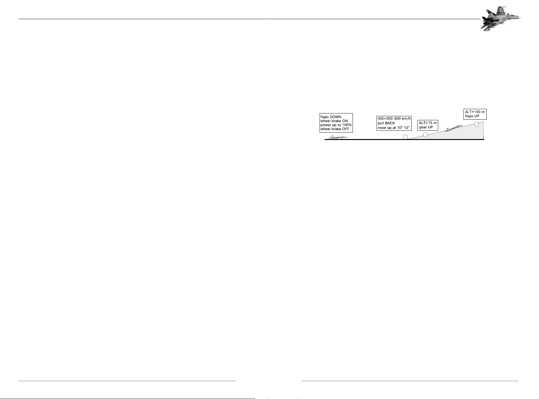
COMMON FLIGHT TASKS
Pilots must learn their aircraft inside and out. We’ve included checklists for most procedures and
emergencies you’re likely to encounter. To practice these procedures, fly the training missions. For
more information, see Flight Training later in this chapter.
Takeoffs
Figure 5-5: Typical Takeoff
Normal Checklist
Takeoff does not usually present too many difficulties, even to beginners. In due course, this procedure will become second nature and will not require much attention. To practice takeoffs, refer
to the appropriate training mission in the Flight Training section.
Normal Takeoff Procedure:
1. If vehicle weight exceeds 25,000kg, extend flaps to take-off position (15 degrees down)
2. Engage wheelbrakes
3. Increase throttle to full military power, or the VFRC position.
4. At 100% RPM, release wheel brakes
5. If vehicle weight under 25,000kg, rotate at 250km/hr. Main gear should lift at 280km/hr.
6. If vehicle weight exceeds 25,000kg, rotate at 280km/hr. Main gear should lift at 320km/hr.
7. Raise gear when altimeter shows a positive rate of climb.
8. When altitude reaches 100m, raise flaps.
Engine Failure on Takeoff
Single-engine takeoffs are extremely dangerous. You can over run the runway without getting airborne or crash shortly after takeoff due to insufficient lift. Should an engine fail during takeoff,
depend on the takeoff weight of the aircraft, length of runway remaining, and the height of obstacles beyond the opposite end of the runway. The following table shows the likelihood of completing a takeoff based on takeoff weight. As you can see, the odds are poor in the best of conditions
and get increasingly worse as weight increases.
CHAPTER 5: Ground School 77
About this time, I realize that the ground is coming up awfully fast. I realize that with this speed, I
can’t physically handle the g-load necessary for a safe turn. My turn radius is too large and I smack
right into the ground. In this case, I blew the energy management by converting my altitude (potential energy) into too much speed (kinetic energy). My turn performance suffered and I crashed.
Energy Management in a Furball
The Western term, “furball” describes a large, multi-aircraft, chaotic dogfight. It’s generally safe to
assume that while you’re stalking one target, one of his companions is stalking you. In such a fight
you need to ensure that you’ve got the energy to make defensive manoeuvres when needed.
Further, separating from the fight is far from a given. Just because you decide you’ve had enough
and want to head home doesn’t mean the bandit on your six is willing to let you go. Opportunities
to escape are few and far between; when one presents itself you’d better have enough energy to
take advantage of it.
Let’s throw three more F-16s and three more Su-27s into the fray described earlier. Now, I have to
keep my eyes peeled both forwards and backwards. It’s not enough to watch the target that I’m
tracking; I must keep an eye out for the bandit sneaking up behind me. The most basic of defensive manoeuvres, the break turn, relies on instantaneous turn capability to quickly increase the
aspect angle between the defender and the attacker. If I’m floundering at 200 km/hr with a bandit
moving in for the kill, I simply don’t have enough energy to execute any kind of reasonable break
turn. Therefore, I choose to maintain an airspeed at or near corner speed throughout the fight. If
I’m saddling up on a target and starting to increase the g-load, I carefully watch my airspeed. If
speed drops too much, I’ll increase power. If speed continues to drop, I have no choice but to
relax the g, roll out, and accelerate, even though it means letting the target escape. By keeping my
speed up, I have the energy to execute hard defensive turns when necessary.
When defensive, try not to over react. Just because there’s a bandit behind me doesn’t necessarily
mean I need to execute a 9g break turn. Imagine an F-15 chasing my Su-27 around a turn circle.
The bandit’s nose position indicates how high a threat he presents. If his nose is pointed well behind
mine, then he most likely is lagging behind me and unable to take a shot. As his nose moves toward
me (and eventually points ahead of my flight path), I know he’s moving into position for a gun shot.
I’ll relax the stick, lower the g-load and accelerate while his nose is “off.” As I see his nose pulling up
for the shot, then I increase aft stick and tighten my turn. As soon as I see his nose fall back, I again
release the stick and accelerate. By using my energy efficiently, I can stave off the F-15’s attack for
quite some time. If I can keep him at bay for just 20 more seconds, maybe he’ll run out of fuel,
maybe he’ll see an exit window and leave the fight, or maybe my wingman will come to my rescue.
Helmet Mounted Sight and Off-Boresight Missiles
Finally, these examples should illustrate the huge tactical advantage IKTV head-tracking avionics
coupled with the R-73 (AA-11). The IKTV mode lets you lock onto targets well above your
nose, and the R-73 (AA-11) missile can engage targets up to 60 degrees aspect angle, giving the
Su-27 a huge energy advantage in a knife fight. While I must still manoeuvre reasonably well, the
decisions I faced in the first two examples diminish. Rather than expending energy in a hard turn to
set up a shot, I simply lock the target using IKTV and fire an R-73 (AA-11). I pull fewer g’s during the fight, keep my speed higher, and have more energy available for subsequent manoeuvreing.
The IKTV system is by no means the be-all and end-all of air combat. The Su-27 is far from
invincible (as demonstrated by repeated dogfights with IKTV -equipped, West German MiG29s), but the system reduces the energy/manoeuvreing demands encountered during a dogfight.
FLANKER 2.0
FLANKER 2.0
76 CHAPTER 5: Ground School
Page 41

9. After reaching 1,500m, evaluate the situation. If possible, execute a 1.2g turn back to the
airbase and land (Use 330 km/hr as the minimum approach speed).
10. If speed drops below 250km/hr, eject immediately.
h Fly the plane first
Although pilots should try to notify the tower of their situation, the pilot’s first
responsibility is to the safety of the aircrew and aircraft. If you’re too busy to talk,
then don’t. Fly the plane first and worry about everything else later.
Landing
Landings often distinguish the good pilots from the mediocre pilots. Landing is often considered
the most difficult and critical part of flying. In the flanker, if the selected airfield is equipped with
the Automatic Landing System (ALS), the autopilot can take care of most landing functions for
you. If the airfield isn’t equipped with the ALS system or your navigation equipment is damaged,
you’ll have to land the old fashioned way. To practice landings, see the landing training mission
described in the Flight Training section.
h Remember: The secret to all good landings is the approach!
For information on locating an airbase, see the “Return Mode” in Chapter 4.
h Move the stick as little and as smoothly as possible!
Automatic Landing
To land the aircraft in automatic mode, engage the autopilot and switch to Return mode. The
autopilot will fly the aircraft to the approach beacon and then switch to the Landing mode (GJC).
Then the autopilot will bring the aircraft down the ILS glide path right to the runway threshold. As
soon as you fly over the runway threshold, the autopilot will change to bank stabilization mode in
which it maintains zero bank angle and damps vertical speed. The autopilot disengages on the
touchdown; 15 seconds after the bank stabilization mode is enable; or when the navigation system loses the ALS beam.
Keep very tight control of your airspeed! Don’t forget to select timely deployment of the aircraft’s
mechanics (gear, flaps, and airbrake) and to brake to a full stop after touchdown. When close to
the threshold you can resume manual control. Both fixed airbases and aircraft carriers are
equipped with ALS systems.
CHAPTER 5: Ground School 79
Table 5-1: Single-Engine Takeoff Success Probabilities Based on Gross Weight
VEHICLE WEIGHT PROBABILITY OF SUCCESS
Under 20,000kg Good
20,000kg to 25,000kg Remote
over 25,000kg Extremely Unlikely
Under 25,000kg the aircraft will usually become airborne. The problem is keeping it airborne long
enough to land again. A single engine barely has enough power to keep the aircraft aloft, turning
or climbing only makes the situation worse. As long as airspeed remains over 320km/hr the aircraft will probably remain airborne. Pilots must fly very carefully with very smooth stick inputs and
the rudder trim correcting for dead engine yaw. The slightest over correction or mistake will result
in disaster. Remember, keep the turn-and-slip indicator’s ball centered.
The best option is to abort the takeoff roll. An Su-27 requires a 620m landing roll. To prevent
running off the far end of the runway, reduce acceleration immediately. The following checklist
describes the procedure for decelerating:
Aborting Takeoff Procedure
1. If less than 600m of runway remains or speed exceeds 270 km/hr, either proceed with take
off or eject.
2. Immediately reduce power.
3. Engage wheelbrake.
4. Deploy drag chute.
5. Deploy flaps and airbrake
If aborting the takeoff is not an option, increase to full power and use all available runway to
accelerate. Do not rotate until the last moment. Once airborne, jettison all external stores immediately and climb. Use the following checklist to maximize chances for success:
Single Engine Takeoff Procedure
1. Lower flaps to takeoff position. Increase all specified speeds by 30 km/hr if flaps are
unavailable.
2. Apply full power.
3. For launch weights under 25,000kg, rotate at 280km/hr. Main gear should lift at 320km/hr.
4. For launch weights over 25,000kg, rotate at 320km/hr. Main gear should lift at 360km/hr.
Single engine takeoffs are not recommended for aircraft weighing over 25,000kg.
5. Apply rudder toward the good engine to counter yaw.
6. Raise gear at positive rate of climb (ROC).
7. Immediately jettison all stores (clear of built up areas).
8. Maintain a level climb to 1,500m. Do not bank the aircraft.
FLANKER 2.0
FLANKER 2.0
78 CHAPTER 5: Ground School
Page 42

h Hold the glide path, keep the intersection of the two ILS bars in the center of the
HUD. Manoeuvre the aircraft gently and control your airspeed to match the
required airspeed displayed.
The HUD also indicates the distance to the beacon. Note that the beacon is not situated at the
runway threshold but at about 300 meters in. This is to ensure that the pilot won’t land short. The
vertical scale to the right indicates your rate of descent (or climb). The MFD shows a symbol of
your aircraft connected with the airfield by a line. The airfield chosen for landing is enclosed in the
square lock frame.
Figure 5-7: HUD symbology in Landing mode with the ALS
You should control airspeed and aircraft configuration as described in the section below.
Visual Approach
If an airfield does not have ILS or the aircraft is beyond the operating range of this system, you
should guide the aircraft to the airfield using information on bearing to the radio beacon, distance to
run and runway heading. In this mode the HUD displays the guidance reticle showing the deviation
of your current heading from the required one, which coincides with the bearing to the radio beacon (see the figure below). Besides, the rate of descent scale to the right helps you control your
vertical speed. At the bottom of the HUD the distance to the airfield radio beacon is displayed.
CHAPTER 5: Ground School 81
Instrument Landing System
After you have reached the approach beacon the navigation system automatically switches to
Landing mode, evidenced by the HUD switching from DJPD to GJC (LANDING) and the aircraft’s Instrument Landing System (ILS) activating. The operating mode of the navigation system
depends on the information being received from the landing systems of a chosen airfield. An airfield can have an automatic landing system and/or a glide path landing system. Depending on
these circumstances, there are two methods of semiautomatic landing.
Many airfields are equipped with the Instrument Landing SystemSee ALS. The ILS generates the
optimum approach trajectory (the glide path) with the help of two mutually perpendicular fanshaped radio beams: Glideslope (horizontal) and Localizer (vertical). The range of the system is
equal to about 25-30 km.
Figure 5-6: The ILS system.
In the figure, the aircraft is flying within the glide path cone, but slight to the right of the runway
center line and a little above the desired glideslope. The ILS bars point the direction to the center
of the runway. The LD bar is displayed along the left side of the HUD indicating the pilot needs to
come left. The GS bar is below the center of the hud, showing the pilot needs to descend. In
other words, fly toward the ILS bars.
During a semiautomatic landing, you can pilot the aircraft using the information displayed on the
HUD, the HSI, and the ADI.
Get on the glide slope early on and hold the aircraft on the glide path. Use the ADI to assist your
approach. It shows information on bank and pitch angles and mismatching heading and altitude.
When landing, you should keep the required bank needle upright and the required pitch indicator
at about the zero position.
FLANKER 2.0
FLANKER 2.0
80 CHAPTER 5: Ground School
Required Airspeed
Required Altitude
Vertical Velocity Scale
ILS Bar
Current Vertical Velocity
Distance To Runway
Return Mode Selected
AOA Indexer
Page 43

Taxiing
If necessary, release the stick and wheel brakes, and taxi along the runway using the rudder
pedals. Retract the air brake and flaps. Relax!
Figure 5-10: Final Approach
Carrier Landings
Carrier landings are the most demanding and dangerous task any nation asks its pilots to perform.
The challenges of landing an aircraft moving 300km/hr on to a moving ship as it pitches and rolls
with the seas requires incredible skill, concentration, and precision. The slightest mistake spells
disaster, placing the aircraft, the aircrew, and the entire ship at risk.
To improve carrier landing success, we suggest you practice the carrier approach pattern at landbased airfield until you can nail the landing every time. Then, once you’re confident you can appropriately control the aircraft, move on to carrier landings.
The carrier landing begins like any other landing. Select the DJPD navigation mode, fly to the
approach point. As you near the initial approach fix, the navigation software automatically switches to the Landing mode. You may perform an automatic landing by engaging the autopilot with the
A key.
Manual Approach
As with all landings, the key to carrier landings lies in the approach, smoothly following the ILS from
the approach point down to the carrier’s deck. It’s very important to stay alert and detect any deviation from the flight path instantly. Flight path corrections must be immediate and aggressive, yet
smooth; do not allow yourself to get “behind” the airplane (that is, let the airplane deviate too far
from the desired flight path). Move the control stick with a graceful motion which flow from one
position to the next. Poor stick control leads to over-corrections and pilot-induced oscillation (PIO).
Above all else, trust your instruments. The ILS displayed on the HUD works the same for carrier
landings as it does for field landings. The ILS will align you with the ship, indicate the required
speed, and display the required altitude. Use the predictor bar on the ADI. These are very precise
and will give you the exact degree of bank and pitch required for the perfect approach.
CHAPTER 5: Ground School 83
A visual approach and landing should be usually made according to the following procedure (see
the figure below).
Figure 5-9: Visual approach landing pattern
Initial Approach
Starting about 10km from the runway, maintain an airspeed of 500 to 600 km /hr at an altitude of
500 to 600m. Align the aircraft with the runway. Arrive over the runway at an altitude of 300m and
an airspeed of 450 to 500 km / hr. As you reach the middle of the runway, execute a 180° turn to
the right (or left as desired) at a 60° to 80° bank angle. You’ll now be heading parallel to the runway but on an opposite heading.
Continue this heading until about 5km from the runway threshold. Lower the landing gear and
extend the speed brake. Decelerate to 400 km / hr, then lower the flaps. Execute the turn to the
base leg (perpendicular to the runway) in the same direction as the last turn. As the runway
approaches your wingtip, turn toward the runway, adjusting the turn rate as necessary to align
with the runway center. Roll out when you’re heading directly down the runway.
Final Approach
At about 5km from the runway, reduce speed to 350 km / hr at an altitude of 250 to 300 meters
and proceed toward the runway. Ideally, cross the runway threshold at 270 to 280 km / hr at an
altitude of 10 to 15 m. You can successfully land, however, after crossing the runway threshold as
slow as 250 km/hr or as high as 50m. Smoothly flair the aircraft while keeping AOA at approximately 10 degrees with a sink rate (rate of descent) about 1 to 1.5 m/s. Sink rates higher than
3.8m/s risks damaging the landing gear on touchdown. If the aircraft sinks too fast, increase
throttle immediately.
The aircraft should touch down at 220 to 250 km / hr. Deploy the drogue chute and cut the
engines to idle. Apply the wheelbrakes. Maintain back pressure on the control stick to keep the
nose up; this uses the aircraft’s airframe as a giant speed brake. Stop or taxi as required.
FLANKER 2.0
FLANKER 2.0
82 CHAPTER 5: Ground School
Page 44

With the appropriate approach path, the
arresting hook should catch one of the
arresting wires strung across the deck.
Multiple wires are stretched across the
landing surface to increase your chances
of connecting with one. It may be difficult
to tell if you’ve caught a wire or not; even
upon successful arrestment the aircraft
will continue forward several meters. As a
precaution, increase throttle to full military
(non-afterburner) thrust and retract the
speed brake as soon as the wheels touch
the deck. If the hook catches a cable, the
aircraft will slow to a stop. If the hook
misses all cables, the increased throttle
ensures you have sufficient power to
become airborne again.
Crosswind Landings
In a crosswind, the task becomes a little more difficult since it is necessary to consider the drift of
the aircraft with respect to the runway heading. To land properly, it is required that the aircraft’s
velocity with respect to the ground should be parallel to the runway heading. This can be achieved
in two ways.
To maintain translational movement in the direction of the ground speed vector (GS), the pilot
should bank a little to the windward wing side while flying towards the runway and flare with a
slight deflection of the stick in the direction of the wind. An increase in crosswind speed as well as
decrease in the aircraft’s true airspeed results in an increase in the slip angle required to compensate for drift. Intense crosswind may lead to maximum deflection of rudders and flaps, which could
make landing impossible.
In the second case, the aircraft develops a heading lead angle and moves without sideslip with
respect to the runway. Hence, there is no need in controlling the position of the rudder and flaps
while closing in to the runway. Right before the touchdown or on the touchdown, line up the aircraft with the runway. As opposed to the first method, this method makes it possible to land at
higher crosswind speeds, yet is more complicated in the piloting technique.
Single Engine Landings
Single engine landings are inherently dangerous. You’re low, slow, and lack the power to climb
away if something goes wrong. You have to fly the correct approach the entire way. A single mistake is often fatal.
Like all landings, success or failure depends on the approach. Using the Return (DJPD) HUD
mode, intercept the initial approach point at 1,000m altitude and 450 km/hr airspeed. Since your
ability to climb is severely limited, fly a little high throughout the entire glidepath and keep your
speed up. Generally, keep your speed and altitude 10% to 20% higher than normal. If you slow
down or drop below the glidepath, you probably don’t have enough thrust to recover. This means
you’ll land “long,” or farther than normal down the runway, but that’s better than crashing in the
grass short of the threshold.
CHAPTER 5: Ground School 85
DJPD navigation mode places your aircraft about 7 to 8km from the ship, flying at an altitude of
approximately 700m and an airspeed of 350 to 400km/hr. Once in GJC mode, lower the gear,
drop the flaps, extend the hook, then turn to center the ILS course deviation bar on the HUD.
Proceeding directly toward the carrier, extend the speed brake to help control airspeed. Follow the
cues displayed on the HUD, keeping the ILS bars centered while maintaining the specified altitude and airspeed.
Continue following the ILS display until
you’re 1km from the ship. At this point,
your airspeed should be down to between
290-310 km/hr, depending upon your
gross weight, at an altitude of roughly 70
meters. Markings on the ship should be
visible by now, giving you additional lineup
cues. Make sure the Glide Path indexer on
the left side of the HUD shows the green,
center light. If your approach is too low the
red light will illuminate. If your approach is
too high, the yellow light will illuminate. If
you are on the glide, the green light will
illuminate. If you’re more than 10 meters
above or below the specified altitude, apply
full power, retract the speed brake, and go
around for another pass.
Figure 5-11b. The Meatball director lights
The final moments of the landing are fast and furious; you’ll touch down at a speed of approximately 310 km/hr. Note the vertical velocity indicator along the right side of the HUD. At touch
down, you should be descending about 6 m/s.
FLANKER 2.0
FLANKER 2.0
84 CHAPTER 5: Ground School
Yellow Light Indicates Moderate Lineup Error
Green Light Indicates Acceptable Alignment
Red Light Indicates Dangerous Lineup Error
figure 5-11c: The final seconds of a carrier approach
Figure 5-11a: 1km From the Ship
Page 45

For speed less than 350 km/hr, the AOA limiter will attempt to keep the Su-27 below 27.5
degrees, and the Su-33 below 30 degrees AOA. Above 350 km/hr, the AOA limiter attempts to
keep both aircraft below 27.5 degrees AOA. These limits can be defeated, though. The limiter can
be disabled using the K key, the pilot can exceed the limits by applying more aft stick when the
limit is reached, and (in some cases) the AOA limiter may not be able to adequately control the
AOA value. Nose-high, low-speed conditions are especially dangerous.
Spin Recognition and Recovery
If the nose yaws during a stall a spin may develop. Depending on the pitch angle at the time of
entry, a spin can be steep or flat. An aircraft in a steep spin rotates with a yaw rate of roughly 110
degrees per second, holds an AOA of roughly 40 to 45 degrees, and pitches down about –30 to
–40 degrees below the horizon. A flat spin is characterized by a high yaw rate of 110 to 140
degrees per second with an AOA in excess of 45 degrees and pitches down about 10-20 degrees
below the horizon.
To recover from a spin:
1) Ensure that power is back to flight idle
2) Centralize the stick.
3) Apply opposite rudder (If the slip ball is right then you are spinning left, so step on the right
rudder. Ball right, step on right rudder).
4) As the rotation slows to zero, centralize the rudder and apply gentle forward pressure to the
stick until the AOA is normal.
5) Add power and accelerate from critical airspeeds and angles.
Typical Steep and Flat Spin Profiles
CHAPTER 5: Ground School 87
h If the aircraft stalls or airspeed falls well below the glideslope, eject immediately!
Ctrl+E 3 times!
Stalls and Spins
As explained earlier, a stall occurs when AOA increases to the point of disrupting airflow over the
wing. This situation will not cease until AOA is reduced. If significant yaw is present during the
stall, a departure from controlled flight called a spin may occur. Pilots pushing their aircraft to the
edge of the performance envelope must always endeavor to avoid these conditions since they
effectively take the pilot out of combat until recovery is completed.
h When passing through 1,500m in an out-of-control situation, eject!
The flight control system will normally limit the aircraft to 27.5 degrees AOA, with stall AOA occurring at 33 degrees. Under normal circumstances, this should keep the aircraft out of trouble; however, there are ways to defeat the system. First, the pilot can override the AOA limiter either by disabling the system or applying an extra 15kg of force to the stick and “pulling through” the limiter.
Also, rudder is generally used to assist turns, especially at low airspeed. However, keep in mind:
1. An intensive rotation in the lateral and directional channels produces a destabilizing pitch
moment which may cause an increase in AOA beyond the permissible limit.
2. High slip angles develop at an AOA approaching the maximum operational value may lead to
an earlier stall.
3. Deflecting the stick in the roll channel at AOAs approaching the maximum operational value
may result in the reverse action (you move the stick left but the aircraft banks right) and possibly an earlier stall.
Stall Recognition and Recovery
At high AOA, the aircraft will start to buffet in the pitch axis, with the intensity increasing at
extreme AOA due to the disruption of airflow over the wing. This buffeting provides an indication
of how close you are to stall AOA. Light buffet indicates you are near the edge of the envelope
and probably achieving maximum turn performance.
When an aircraft stalls, lift is greatly reduced. As explained above, turn performance depends
greatly on g-load. Consequently, a stalled aircraft generally stops turning. Momentum causes the
aircraft to move in a straight line tangent to the original turn circle. This can be disastrous in a
dogfight or when attempting to evade an incoming missile. Buffet, therefore, is the “warning” that
you’re pushing the edge of the envelope and are risking a stall.
In flying at high AOA and low speeds, be very careful and very gentle with the stick inputs. Even
the slightest pitch increase could result in a stall. Be very smooth with the stick inputs. If buffet
increases in intensity, reduce back pressure on the stick.
FLANKER 2.0
FLANKER 2.0
86 CHAPTER 5: Ground School
Page 46

The tailslide
This manoeuvre is demonstrated by the Flanker at air shows and is arguably considered of little
combat value. However, the experts assert that when an aircraft slows down at the top of the tail
slide, it effectively “beams” all modern enemy radar systems (at the expense of all its airspeed).
Along with the famous Cobra manoeuvre, the tail slide dramatically demonstrates the Flanker’s
staggering capability to remain stable at high angles of attack and low airspeeds and definitely
shows superb engine design.
A typical tail slide is shown on the diagram below:
1. Start a climb to the near vertical (70° pitch angle).
2. Once established on a stable 70 degree nose up trajectory, reduce power to idle and maintain the 70 degree angle. Extra care should be exercised if the pitch angles go beyond 75, as
excessive pulling back on the stick may result in an overshoot in pitch beyond the vertical
and potential deceleration into high negative AOAs.
3. After the aircraft has begun to fall (develops negative vertical velocity), bring the stick
smoothly back.
4. The aircraft will fall forward and nose down. Compensate for any tendency to spin right with
the left rudder (the Z key). This tendency right is due to the gyroscopic effect generated by
the engines. In the real aircraft you would also use some right engine input to compensate for
this effect, but unfortunately only a few of you will have split throttles connected to your PC.
5. Bring the power up to 100% and let the aircraft accelerate to approximately 500 km/h, then
level off normally.
FLIGHT TRAINING
Now that you understand the concepts behind air combat, it’s time to see them in practice. In the
next chapter, we’ve developed a series of training missions designed to talk you through basic
flight manoeuvres while our instructor pilot talks you through them.
CHAPTER 5: Ground School 89
Aerobatics
A testament to the quality of its design, the Su-27 and subsequent variants have substantial aerobatic capabilities. While the combat effectiveness of some of the more exotic manoeuvres remains
a topic of debate, such performances are crowd favorites at airshows around the world.
Pugachev’s Cobra
Pugachev’s Cobra or dynamic braking is a manoeuvre in which within 3-4 seconds the nose of the
aircraft is pulled up to high angles of attack (80-110°) and then returned to normal horizontal
flight. This causes intensive loss of airspeed. You can execute this manoeuvre from level flight at
various altitudes and at indicated airspeeds of 350-450 km/h. The figure below illustrates a typical
Cobra manoeuvre:
Cobra Manoeuvre
In level flight at the appropriate entry speed of 350 to 450 km/h, disable the AOA limiter by pressing the K key. Execute the cobra by pulling the stick fully aft. As the nose reaches the vertical
(pointed straight up) allow the stick to go to neutral and let the nose fall back down to level flight.
Smoothly increase thrust towards the end of the manoeuvre. The AOA limiter will automatically reengage after executing the cobra.
Tailslide
A tail slide (also known as the “bell” in Russian) is a zoom manoeuvre executed at a high pitch
angle (70-75°). It results in a drop of vertical speed to zero though the horizontal airspeed remains
above zero at 10-20 km/h. Then the aircraft will slide downwards for up to 100 m and then executes a turn in pitch with a recovery to level flight. A typical tail slide may be executed starting at
different altitudes and at airspeeds of 500-800 km/h.
FLANKER 2.0
FLANKER 2.0
88 CHAPTER 5: Ground School
Page 47

CHAPTER 6: Introduction to Flanker Weapons 91
INTRODUCTION TO FLANKER WEAPONS
From somewhat modest beginnings in WWI, airpower quickly gained acceptance and thoroughly
changed the nature of combat. While ground troops are required to take and hold territory, support from the air (whether releasing weapons, delivering supplies, or deploying forward troops)
has become instrumental in every major military’s operational doctrine. Obtaining air superiority
and denying the enemy usage of his aircraft has become one of their prime objectives. With the
ability to cover hundreds of miles in only a few hours, aircraft have also changed the nature of
power projection. A floating runway called an aircraft carrier can have aircraft on station mere
hours after an outbreak of trouble! Air power assumes many roles on the modern battlefield, and
the Flanker family is well-designed to accomplish those roles. The Su-27’s primary mission is air
superiority; the Su-33 multi-role fighter handles both air-to-air and air-to-ground tasks admirably.
In any case, the ultimate role of a fighter aircraft is to deliver weapons on target and return safely.
In this chapter we’ll teach you how to do exactly that. Here we’ll examine the capabilities of the
weapons on hand and how to best employ them.
AIR-TO-AIR WEAPONS
The Flanker carries a mixture of radar-guided air-to-air missiles, heat-seeking air-to-air missiles, and
30mm cannon, giving it the ability to engage airborne targets under a wide variety of circumstances.
Each weapon type has strength and weaknesses along with performance nuances. Successful airto-air combat depends on a thorough understanding of the weapons and their limitations.
The GSh-301 Cannon
The gun is the most basic of air combat weapons. Although many believed the advent of air-to-air
guided missiles would make the gun obsolete, repeated experience has shown that the gun
remains an integral part of an aircraft’s weapons package. The Flanker carries 150 rounds of
30mm ammunition capable of inflicting serious damage on an enemy aircraft. Activate the cannon
mode by pressing the C key from any air-to-air mode or while in air-to-ground mode.
CHAPTER 6
Weapons
CHAPTER 6
Weapons
Defense Visual Information Center - Department of Defense
Page 48

As you close inside 1,400 meters, the symbology changes. The range bar disappears and aiming
crosshairs, also called the “pipper”, appear. The circle around the aiming crosshairs now represents
the range to the target; the arc of the circle recedes counterclockwise as you get closer. The smaller the arc, the closer you are to the target. A full circle indicates the target is 1400 meters away.
To shoot the target, manoeuvre the pipper over the aiming reticle. When the computer calculates
that you’re in range, the shoot cue will appear. If you approach the target too close, the HUD may
show the Reject Cue JND.
If the target manages to break the tracking lock, the HUD switches to the standard gun funnel
mode. To re-establish the lock, disable the cannon by pressing C and repeat the target lock
sequence using either the radar.
Using the Cannon Funnel
In the event that the radar and EOS are unavailable or your are unable to achieve a lock, you can use
the funnel display to manually aim the guns. The funnel appears whenever you enable the cannon
(by pressing C) without having first acquired a lock. The funnel is designed to indicate the required
amount of lead angle when firing at a fighter-sized target 200m to 800m away.
The funnel consists of two curved lines. The distance between the two lines represents a width of
15m (the approximate wingspan of many fighter-sized targets) at varying ranges from 200m (top
of the funnel) to 800m (bottom of the funnel). To use the funnel, bank your aircraft until the horizontal line in the middle is parallel to the target’s wings (indicating you are in the same plane of
manoeuvre as the target). Pull lead until the wingtips of the target just touch the two outer edges
of the funnel. The further away the target is, the smaller its wingspan appears, so the further down
the funnel you place it, thereby increasing the amount of lead you’re pulling. Rounds fired now will
impact the target.
6-5: The Gunnery Funnel
CHAPTER 6: Air-to-Air Weapons 93
Using Radar or Electro-Optical System (EOS) Targeting
Fortunately, the radar and EOS simplify the task of aerial gunnery by accurately measuring the
range to the target and providing helpful cues on the HUD. Locking a target in Close Air Combat
or Helmet Mounted Sight modes greatly improves the chances of hitting the target.
Once the target has been locked, extra cues appear on the HUD. The left side of the HUD shows
the “Autotrack” cue (indicating the system is operational and tracking a target) along with a vertical range bar. The range bar provides three types of information at once:
1. Range to target – The arrow symbol along the right side of the range bar indicates how far
away the target is. The marks along the left side of the bar help estimate the distance.
2. Effective cannon range – The marks along the right side of the bar indicate the cannon’s maximum and minimum firing ranges.
3. Aspect angle - The pointed arrow affixed to the bottom of the range bar shows the target’s
heading relative to yours. If the arrow points straight up, you’re directly behind the target. If
the arrow points straight down, the target is heading directly at you.
6-3: The Autotrack HUD Symbology (Range > 1400 meters)
As usual when locking a target, the target’s airspeed and altitude are displayed above your own.
The number of cannon rounds remaining is displayed in the lower right corner of the HUD. The
aiming reticle is superimposed over the target as long as you maintain the lock.
h In general, steer your aircraft to keep the aiming reticle near the center of the
HUD; this prevents the target from breaking the lock with a sudden manoeuvre.
FLANKER 2.0
FLANKER 2.0
92 CHAPTER 6: Air-to-Air Weapons
Page 49
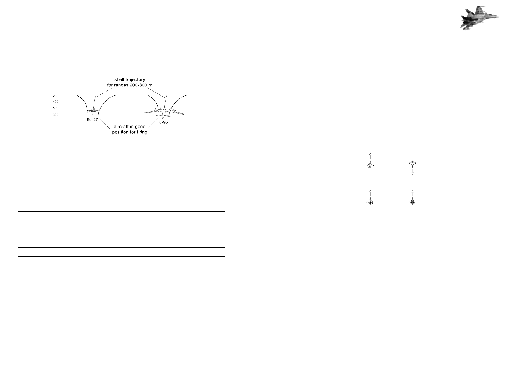
Kinematic Range Against Non-Manoeuvreing Targets
Like aircraft, a missile’s biggest problem is thrust. Missiles have a very limited amount of space for
onboard fuel. Consequently, a missile’s engine burns for a very short time (just a few seconds in
some cases) and quickly accelerates the missile to maximum speed. The motor then burns out and
the missile relies on its rapidly decaying momentum to reach the target. As with aircraft, the missile’s turn performance is dependent upon how many g’s it can pull. The slower the missile is, the
less g’s it can pull. The maximum range at which the missile is effective against a non-manoeuvreing target is called its kinematic range. As we’ll see later, however, “range” is a very elusive topic.
Target aspect angle has a large impact on the missile’s effective range. As shown in figure 6-7, a
target heading directly at the missile covers part of the range. The shooter can fire the missile earlier since the target flies toward the missile, shortening the missile’s time of flight. Conversely, a tail
aspect greatly reduces missile range since the target is running away from the missile. Suppose
the missile is fired at a target 10km away. It takes the missile several seconds to travel that distance. By the time the missile has flown 10km, the target may have moved another one or two
kilometers further away. Missiles are substantially faster than aircraft, but run out of fuel much
faster as well.
6-7: Effects of Head and Tail Aspect Angles on Missile Kinematic Range
The left-hand illustration in figure 6-8 shows a typical envelope for a missile fired at a nonmanoeuvreing target (in the center of the diagram). The grey zone represents the ranges from
which the missile may be fired based on aspect angle. Notice that when fired head-on, the range
is significantly longer than when fired from behind. The white area around target defines the minimum range requirements for the missile. Since directly hitting the target is unlikely, most missile
warheads are designed to emit some form of shrapnel in order to damage nearby aircraft. To prevent the launching aircraft from inadvertently being damaged by the missile explosion, the missile
does not arm until it has flown a safe distance from the shooter. Also, the missile seeker or guidance system may require some amount of time to engage the target. The distance the missile must
fly is known as the minimum range.
CHAPTER 6: Air-to-Air Weapons 95
What happens if the target’s wingspan is greater than (or less than) 15m? The funnel specifically
represents a wingspan of 15m; against larger or smaller targets you’ll have to estimate the difference. For example, a large target like a Tu-95 has a wingspan of roughly 50m and will overlap the
funnel. Figure 6-6 illustrates, comparing an Su-27 and a Tu-95 700m away:
6-6: Comparing Target Wingspans with the Targeting Funnel
The following table shows the wingspans (minimum and maximum for variable-geometry aircraft)
that you’re likely to encounter. When engaging a target smaller or larger than 15m, remember to
adjust the funnel accordingly. If the target is smaller, don’t pull as much lead. If the target is larger,
pull more lead than indicated by the funnel.
AIRCRAFT WINGSPAN, M AIRCRAFT WINGSPAN, M
MiG-23 7.8/14 Tu-22 23.6
MiG-27 7.8/14 Tu-95 50.05
MiG-29 11.36 Tu-142 51.1
MiG-31 13.46 Il-76 50.3
Su-24 10.36/17.63 A-50 50.3
Su-25 14.36 F-15 13.1
Su-27 14.72 F-16 9.4
Air-to-Air Missiles
Missiles:Air-to-air;Missiles are not “magic bullets” by any stretch of the imagination. Like aircraft,
they must obey the laws of physics and have very specific flight envelopes. When fired within the
appropriate parameters, missiles have a deadly performance advantage over aircraft. When fired in
marginal situations, however, the missile’s chances of success goes down dramatically.
FLANKER 2.0
FLANKER 2.0
94 CHAPTER 6: Air-to-Air Weapons
Page 50
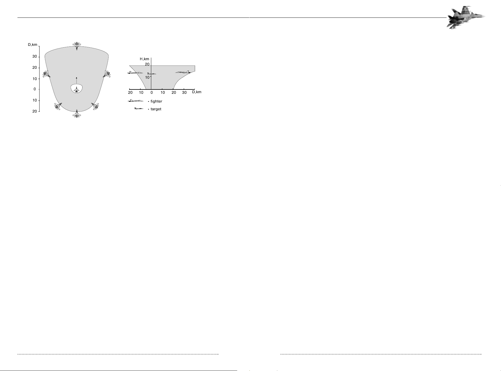
aircraft in the world can turn fast enough and accelerate fast enough to escape. That same missile,
though, may be unable to catch an aircraft performing a 6.5g drag turn 25km away.
The target may also attempt to “beam” the missile by turning toward the missile to place the
inbound missile at either the 3 o’clock or 9 o’clock position, then maintaining a sufficient turn to
keep the missile there. This forces the missile to execute a continuous turn, bleeding speed and
energy all the while. The target may also turn away to place the missile at the beam position as
well. In any event, the target is trying to make the missile expend as much energy as possible,
which shortens its range and its manoeuvreability.
Conclusion
From this we see that “missile range” is a very complex topic. Merely knowing that a missile
has a 30km range doesn’t do much good… when fired from what altitude? When the target is
at what altitude? Against what aspect angle? At what airspeed? Overall, we can draw two
main conclusions:
1. The closer you are to the target when you shoot, the better the chances that your missile will
hit the target. Missiles fired at or near their maximum range (for the given circumstances) are
not very likely to hit.
2. Launching from higher airspeed and altitudes significantly increases the missile’s effective
range.
Missile Guidance
The missile’s guidance systems provide inputs to the missile’s control system, which in turn
manoeuvres the missile to intercept the target. Most modern AAMs are based on homing guidance. When homing, the guidance law is formed in the missile’s computer using information on
target motion. There are three types of homing: passive, semi-active, and active.
The simplest of these types, passive homing relies on emissions given off by the target itself (radio,
heat, light, sound). In case of active and semi-active homing, the target is illuminated (usually by
radar or laser), and the homing system guides on the illumination energy reflected off the target.
For active homing guidance the missile itself illuminates and tracks the target. Semi-active homing
implies that some source external to the missile (for example, the radar of the launching platform)
illuminates the target.
Some missiles, especially long range ones, use combined guidance: inertial radio-corrected guidance and homing on the terminal part of flight. To implement inertial guidance, the launching aircraft computer feeds into the missile’s control system information on target coordinates, trajectory
and relative speed.
After the missile has started, its guidance system uses the information about the relative position
of the missile and the interception point computed by the navigation system. During the flight of
the missile, the interception point may significantly change. For this reason, radio correction supplements the inertial guidance. This increases the accuracy with which the missile reaches the
target area. Upon approaching to the target, the guidance system switches to homing, passive
or active.
CHAPTER 6: Air-to-Air Weapons 97
6-8: A Typical Missile Envelope Against a Co-altitude, Non-manoeuvreing Target
Notice the right-hand illustration in figure 6-8. This shows the second major factor in missile
range: altitude. Generally speaking, a missile’s kinematic range doubles for each 6,100m (20,000
feet) that altitude is increased. For example, if the missile’s kinematic range is 20km at sea level, it
will double to approximately 40km when fired at a co-altitude target 6,100m higher. At 12,200m
(approximately 40,000 feet), missile range would increase to 80km. When fired at a higher or
lower target, the missile’s range is generally associated with the median altitude between the
shooter and the target (assuming the missile can climb high enough when fired at a higher altitude target).
Finally, the speed of the launching aircraft greatly impacts missile kinematic range. The slower the
launcher is moving, the longer the missile will take to reach maximum speed. More of its limited
motor burn will be spent accelerating to cruise speed. If the missile is launched at a higher speed,
it will reach cruise speed and altitude faster, saving more of the motor burn for the “cruise” portion
of the flight. Likewise, the speed of the target impacts the missile range as well. The faster the target is moving, the more distance it will cover during the missile’s time of flight. In a tail-chase scenario, the target may escape the missile’s maximum range. In a head-on scenario, the target may
close inside the missile’s minimum range!
Manoeuvreing Targets and Missile Evasion
Unfortunately, target aircraft rarely cooperate with your plans and often attempt to evade your missiles. So far, we have not discussed how target manoeuvreing affects missile performance. When
fired at a manoeuvreing target, the missile will follow a curved trajectory to the target. This increases drag, bleeds speed, and reduces the missile’s effective range.
The target may attempt to “drag” the missile; in this case the target executes a high-g turn until it
facing directly away from the missile, then unload to 1g and accelerate directly away from the
incoming missile. In this case, the target is attempting to place the missile in the shorter “tail
aspect” portion of its flight envelope. Success depends primarily on how quickly the target can
turn (a light fighter may execute an 8g or 9g turn, a heavily laden attack aircraft may be limited to
5g or 6g) and how quickly it can accelerate after bleeding speed away in that turn. Modern,
more-capable missiles may have a no-escape zone; that is, at a given range (say 10km), no
FLANKER 2.0
FLANKER 2.0
96 CHAPTER 6: Air-to-Air Weapons
Page 51
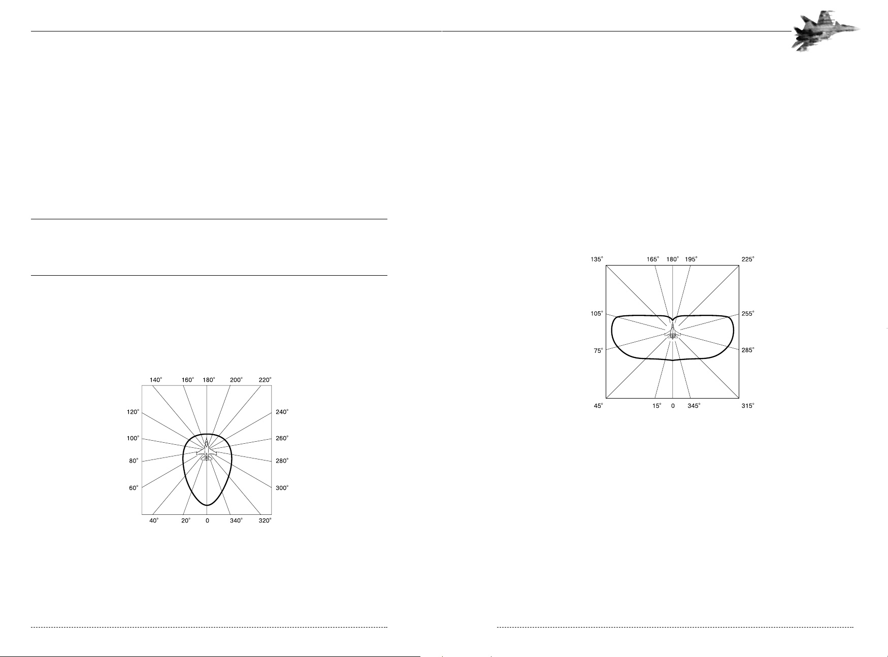
One of the major drawbacks of passive homing is its dependence on a “cooperative” target that
continues to emit the energy required for homing. Besides, IR energy is absorbed and dissipated
by water vapor, making heat seekers all but useless in clouds or rain. Discrimination between the
target and background radiation generated by the sun, reflections off water, snow, clouds and hot
terrain such as deserts can also be a problem for IR seekers.
Semi-active and Active Homing
For semi-active and active homing, a missile uses a radar seeker head. Radar-guided missiles are
currently the most widely used all-weather AAMs. Here the power of radio emission from a target
and the sensitivity of the receiver determine the missile’s ability to track the target. As this case
involves reflected radiation, its intensity depends on the power of the illuminating source and on
the target’s ability to reflect radio waves; i.e., it’s radar cross section (RCS). This ability significantly
depends on the aspect angle of the target. Besides aspect angle, the reflection of radio waves
depends on the size, shape and details of construction of the target. The figure below shows a
typical diagram of reflected signal intensity:
6-10: Radar Cross Section Illustrated
Although semi-active homing provides acquisition of uncooperative targets and is good for long
distances, one of its major problems is greatly increased complexity which results in reduced reliability. Essentially this technique requires two separate tracking systems to be successful (one in
the missile, the other in the guidance platform). Another serious drawback is the requirement for
target illumination by the guidance platform throughout the missile’s flight. This requirement makes
the illuminator vulnerable to passive-homing weapons, and with airborne illuminators it often
restricts the manoeuvreing option of the aircraft providing target illumination.
Although active homing requires a more complex, larger and more expensive missile, the total
guidance system is no more involved than that of the semi-active system, and in some ways it is
simpler and more reliable. It also gives the launching platform “fire-and-forget” capability, as do
passive systems. One disadvantage, however, is the possibility of reduced target detection and
tracking ranges. Since the range of target acquisition is proportional to the area of the illuminating
CHAPTER 6: Air-to-Air Weapons 99
To home, a missile needs a device that will receive radiation from a target (sense it) and track the
target. This device, known as a seeker, is located in the nose of the missile. However, semi-active
homers may include a rear receiver for reception of information from the illuminating platform.
Active homers contain a transmitter and receiver generally located forward. Depending on the
type of radiation received by the missile, the seeker may be of infrared or radar type.
Passive Homing
Most seekers with passive homing are infrared (IR) seekers reacting to heat-radiating objects.
This device contains a material sensitive to heat (IR radiation) that is produced primarily by the
target’s propulsion system. The detector is often cryogenically cooled to eliminate internally generated temperature and allow detection of even very small amounts of IR energy coming from an
external source.
h Passive seekers have an inherent advantage in their maximum range because
their received power is inversely proportional to the square of the target range. The
maximum range of active and semi-active systems varies inversely with the fourth
power of the transmitter strength.
The range at which an IR seeker can see a target depends on the intensity of IR-radiation emitted
by the target in the direction of the sensor and the seeker sensitivity. Therefore, the track range of
the IR seeker depends very much on the engine operating mode of the aircraft being tracked and
on the aspect angle, reaching its maximum value for attacks in the rear quarter.
The figure below presents a diagram of the IR-radiation intensity by a single-engined aircraft in the
horizontal plane.
6-9: IR Radiation Intensity
After the launch, a missile using passive homing becomes completely autonomous and is known
as “fire-and-forget”. If an IR seeker provides tracking of a target at any aspect angle, the seeker is
said to be all-aspect, otherwise it is a rear-aspect seeker.
FLANKER 2.0
FLANKER 2.0
98 CHAPTER 6: Air-to-Air Weapons
Page 52
The purpose of a missile fuse system is to cause the detonation of the warhead at the time that
produces the maximum target damage. Fuses can be classified as contact, time delay, command,
and proximity. Contact fuses are activated upon contact with the target. This type of fuze is often
used in combination with another type. Time-delay fuses are pre-set before launch to explode at a
given time that is calculated to place the missile in the vicinity of the target. Command fuses are
activated by radio commands from the guidance platform when the tracking system indicates that
the missile has reached its closest point to the target.
Modern AAMs mostly use proximity fuses which are probably the most effective against manoeuvreing targets. They come in many designs including active, semi-active, and passive. An active
fuze sends out some sort of signal and activates when it receives a reflection from the target.
Semi-active fuses generally function on an interaction between the guidance system and the target. Passive fuses rely for their activation on a phenomenon associated with the target. This might
be noise, heat, radio emissions, etc.
Proximity fuses are usually tailored to the guidance trajectory of the missile, the most probable target, and the most likely intercept geometry. They determine the closure rate, bearing, distance to
the target, and other parameters. This ensures high combat efficiency of the warhead by rationally
matching a fuze detonation area and a fragment spread area generally forming a cone-shaped
lethal volume ahead of the warhead detonation point.
6-11: Fuze Detonation Patterns
Note that modern AAMs contain a self-destruct mechanism in case the missile loses lock or control.
The pilot selects a particular type of missile depending on distance to the target and its manoeuvreability. Considering these characteristics, AA missiles can be divided into long-range, mediumrange, and close air combat missiles.
CHAPTER 6: Air-to-Air Weapons 101
antenna, all other factors being equal, the tracking range of the aircraft radar greatly surpasses
that of the missile. Therefore, semi-active homing is possible at considerably greater distances
than active homing. That is why active homing is frequently used in a combination with inertial
guidance or semi-active homing and sometimes passive homing.
Target Tracking
A variety of guidance laws are implemented in modern AAMs. Most missiles that employ proportional navigation techniques require a moveable seeker to keep track of the target. Such seekers
have physical stops in all directions, called gimbal limits, which restrict their field of vision and
therefore limit the amount of lead the missile may develop. If the seeker hits the gimbal limit, the
missile usually loses its guidance capability, i.e. “goes ballistic”. Such a situation most often develops when the line of sight to the target moves fast and the missile’s speed advantage over the
target is low.
Using onboard systems, the pilot searches, detects and acquires a target, then feeds the targeting
data into the selected weapon. The missile can be launched if the current targeting data fit the
characteristics of the guidance system of the chosen type of missiles. (For example, the aspect
angle to the target falls within the gimbal limits of the seeker, and the intensity of radiation from
the target is within the sensitivity limits of the seeker).
The pilot can launch the missile when it falls within the limits of the possible launch zone, which is
usually calculated by the aircraft’s onboard computer. The computer displays on the HUD information about the maximum and minimum range of launch and lights the GH– shoot cue (Russian
designation for Launch Allowed, pronounced ‘pe-er’) when the missile is ready.
Target Destruction
The warheads used in AAMs are typically blast-fragmentation, creating a cloud of incendiary/explosive pellets or an expanding metal rod. Blast fragmentation warheads cause damage through the
combined effects of the explosive shock wave and high-velocity fragments (usually pieces of the
warhead casing). Pellet designs are similar, except some of the fragments are actually small
bomblets that explode or burn on contact with, or penetration of, the target. The damage to airborne targets from blast effect alone is not usually great unless the missile actually hits the target.
Fragments tend to spread out from the point of the explosion, rapidly losing killing power as miss
distance increases. Pellets reduce this problem somewhat since a single hit can do more damage.
The expanding-rod warheads have metal rods densely packed on the lateral surface of an explosive
charge in one or several layers. The ends of these rods are welded in pairs so that while spreading
after the explosion of the charge they form a solid extending spiral-shaped ring.
The lethality of a warhead depends largely on the amount of explosive material and the number
and size of the fragments. Larger expected miss distances and imprecise fuses require bigger
warheads. The greater the weight of the warhead, the more effectively it destroys the target.
However, the larger the warhead the greater the overall weight of the missile and hence the less
manoeuvreable it is.
FLANKER 2.0
FLANKER 2.0
100 CHAPTER 6: Air-to-Air Weapons
Page 53

The R-27 is effective against highly manoeuvreable aircraft, helicopters, and cruise missiles. It can
destroy targets at any aspect angle, both in daylight and at night, in good or bad weather. Its
guidance system is resistant to natural interference and ECM, and capable of tracking targets
against ground and water clutter. The R-27 can engage targets ranging in altitude from 25 m to
20 km with elevation up to 10 km. The targets can fly at speeds up to 3500 km/h and with g-load
up to 8 Gs.
The R-27 has a large number of versions equipped with various seeker heads. The basic semiactive radar homing (SARH) version is the R-27R (‘Alamo-A’), often carried in conjunction with an
R-27T (‘Alamo-B’) IR-homing missile so that pairs of SARH and IR-homing missiles can be “ripple-fired” for improved kill probability. Long-range versions of both missiles have a new boost sustain motor and are externally recognizable by their increased body length and a slightly “fattened”
rear fuselage. These are designated R-27Re and R-27TE respectively. Two other variants are the
R-27EM with an improved SARH seeker for better performance against low-flying and sea-skimming missiles, and the R-27AE with active radar terminal homing. The Su-27 standard warload
includes six R-27s.
MAXIMUM RANGE AT HIGH
VERSION RUSSIAN GUIDANCE ALTITUDE/LOW ALTITUDE, KM
R-27R P-27 Inertial radio-corrected guidance and 80/10
semi-active radar terminal homing
R-27T P-27 All-aspect passive infrared homing 72/10
R-27RE P-27 The same as in R-27R 170/30
R-27TE P-27 The same as in R-27T 120/15
R-27EM P-27BV Inertial radio-corrected guidance and 120/20
semi-active radar terminal homing
(able to destroy cruise missiles at a
height of 3 m above water surface)
R-27AE P-27FB Inertial radio-corrected guidance and 120/20
active radar terminal homing
R-77 / AA-12 Adder
The Vympel R-77 (AA-12 ‘Adder’) is a new-generation medium-range AAM. This missile is unofficially dubbed “AMRAAMski” in the West. The R-77 entered limited production in 1992 and is primarily intended for the new advanced versions of the Su-27 and MiG-29. The missile employs
radio command guidance on the initial part of flight and active radar homing on approach to the
target (15 km and less).
Æ
Æ
CHAPTER 6: Air-to-Air Weapons 103
Long Range Missiles
R-33E / AA-9 Amos
The R-33E (USA/NATO designation: AA-9/’Amos’) designed by the Vympel OKB is a long range
guided missile with an operating range up to 160 km. The missile employs inertial control and
semi-active radar guidance on the terminal segment of flight. The R-33E is used to intercept aircraft and cruise missiles, that is why it is the principal missile of the MiG-31 Foxhound. The missile
is capable of destroying targets ranging in altitude from 25 m to 28 km and flying at speeds up to
Mach 3.5. Relative difference in altitudes of the missile and the target can be up to 10 km. The
R-33E flies at Mach 4.5.
Medium Range Missiles
R-23 / AA-7 Apex
The Vympel R-23 (AA-7 ‘Apex’) medium-range missile comes in two modifications with different
seeker types. The R-23R (‘AA-7A’) has a semi-active radar seeker while the R-23T (‘AA-7B’) has
an IR seeker. Both the missiles have a maximum range of about 25-35 km. An older missile, the
R-23 is often replaced by the more powerful and intelligent R-27 ‘Alamo’.
R-27 / AA-10 Alamo
AA-10 Alamo (See Also AA-10; R-27;The Vympel R-27 (AA-10 ‘Alamo’) is the primary mediumrange AAM for the Su-27 and is available in several variants. The R-27 entered production in 1982
specifically for use on the new MiG-29 and Su-27 in place of the R-23 ‘Apex’ used by the MiG-23.
FLANKER 2.0
FLANKER 2.0
102 CHAPTER 6: Air-to-Air Weapons
Page 54
The table below contains the comparative characteristics of various types of modern Russian
AAMs. The maximum number of a specific type of weapon that can be carried is shown next to
the aircraft designation in parentheses.
RANGE, KM
(MAXIMUM RANGE
TYPE RUSSIAN USA/NATO CARRIER (#) WEIGHT, KG SEEKER AT HIGH ALTITUDE)
R-23R P-23H AA-7A/Apex MiG-23 (2) 223 SARH 35/25
R-23T P-23N AA-7B/ Apex MiG-23 (2) 217 IR 35/25
R-27R P-27H AA-10A/Alamo-A MiG-29 (4), 253 SARH 80
Su-27 (6),
Su-33
R-27T P-27N AA-10B/Alamo-B MiG-29 (4), 254 IR 72
Su-27 (6),
Su-33
R-27RE P-27H AA-10C/Alamo-C MiG-29 (4), 350 SARH 170
Su-27 (6),
Su-33
R-27TE P-27N AA-10D/Alamo-D MiG-29 (4), 343 IR 120
Su-27 (6),
Su-33
R-33A P-33F AA-9/Amos MiG-31 (6) 490 SARH 160
R-60 P-60 AA-8/Aphid Su-24 (2), 45 IR 10
Su-25 (2),
MiG-23 (4),
MiG-27 (2)
R-73 P-73 AA-11/Archer MiG-29 (6), 110 IR 30
MiG-31 (4),
Su-24 (2),
Su-25 (2),
Su-27 (10),
Su-33
R-77 P-77 AA-12/Adder MiG-29 (6), 175 Radio 90
MiG-31 (4), command
Su-25 (2), +ARH
Su-27 (10),
Su-33
Æ
Æ
CHAPTER 6: Air-to-Air Weapons 105
The R-77 can be effectively used against highly manoeuvreable aircraft, cruise missiles, AAMs and
SAMs, strategic bombers, helicopters (including helicopters in hover mode). It can destroy targets
moving in any direction and at any aspect angle, in daytime and at night, in good or bad weather.
Its guidance system is resistant to ECM and is capable of tracking targets against ground and
water clutter. Maximum operating range is 90 km. The missile can attack targets at aspect angles
up to 90°. The R-77 has a maximum speed at high altitude of Mach 4.0.
Close Air Combat Missiles
R-60 / AA-8 Aphid
The R-60 (AA-8 ‘Aphid’) missile is a close air combat missile with all-aspect infrared passive homing. The maximum operating range is 10 km. The missile normally flies at Mach 2. The R-60 can be
carried practically by any Russian combat aircraft and by many helicopters, though it is now considered obsolete and often replaced by the more intelligent R-73.
R-73 / AA-11 Archer
The Vympel R-73 (AA-11 ‘Archer’) was developed as a replacement for the R-60 and is the first of
a new generation of highly manoeuvreable missiles for close air combat. The missile employs IR
passive homing and has been described as being “a decade ahead of current Sidewinder” variants, and as the most sophisticated IR-guided AAM in service. The R-73 has a new level of agility
and is capable of off-axis launch from all aspects. It has a very wide-angle sensor which can be
slaved to the pilot’s helmet-mounted sight, allowing the missile to be locked up at targets up to
60° from the aircraft axis. The missile can be launched from aircraft pulling up to 8.5 Gs.
The R-73 employs aerodynamic control combined with vectored thrust. Tremendous manoeuvreability (up to 12 Gs) is conferred by the missile’s combination of forward-mounted canard fins,
rudderons on the fixed tailfins, and deflector vanes in the rocket nozzle.
The missile has a 7.4-kg expanding rod warhead and can destroy targets at altitudes of as low as
5 meters and at ranges up to 30 km. The R-73 normally flies at Mach 2.5.
FLANKER 2.0
FLANKER 2.0
104 CHAPTER 6: Air-to-Air Weapons
Page 55

6-12: Laser Designation Scenarios
Kh-29 / AS-14 Kedge
The most common air-to-ground guided missile is the Kh-29 (AS-14 ‘Kedge’). The weapon is
effective against hardened targets (such as reinforced concrete shelters, concrete runways, major
railway and highway bridges) and sea-based targets (ships and surfaced submarines). The
weapon should be launched from an altitude between 200 meters and 5 km. Maximum launch
range for the Kh-29 is about 10-12 km and maximum speed is 3000 km/h. The Kh-29 comes in
the following major versions:
VERSION GUIDANCE WARHEAD, KG RANGE, KM
X-29L Semi-active laser homing 317 8-10
X-29TE TV or passive IR homing. 320 20-30
The Kh-29T fire-and-forget version is capable of destroying large tonnage ships (up to 10000-ton
displacement) such as torpedo boat or cruiser.
CHAPTER 6: Air-to-Ground Weapons 107
AIR-TO-GROUND WEAPONS
While the Su-27 was originally designed as an air-to-air interceptor, the carrier-based multi-role
Su-33 carries a wide variety of air-to-ground ordnance including missiles, unguided rockets, and
free-fall bombs. In this chapter we examine the different weapons, their capabilities, and their
intended roles.
h Use the right tool for the right job! Each weapon type is designed for a specific
purpose. An anti-radiation missile is useless against trucks and vans. High-explosive, penetrating bombs aren’t very effective against dispersed SAM sites. Before
executing a mission, research the target and carry weapons appropriate for the
task at hand.
Air-to-ground Missiles
Just as air-to-air missiles are tailored for long, medium, and close ranges, air-to-ground missiles
are tailored to specific target types. The warheads and seekers are usually designed for specific
purposes, such as attacking hostile radar sites and enemy ships; however, a few missiles are
designed as “general purpose” weapons.
General purpose tactical missiles
General purpose tactical missiles include the Kh-29 and Kh-25 families. These missiles can destroy
field fortifications, railway and highway bridges, runways, bunkers, fortified missile launchers, ships,
and surfaced submarines. The missiles are powered by solid-propellant rocket motors, which have
a burn of some seconds and ensures initial boost up to speeds of about 2000-2300 km/h.
Guidance Types
Air-to-ground missiles use a variety of guidance types. Passive (non-emitting) systems use television or infrared guidance. For television guidance, the pilot designates the target via a picture displayed on the MFD and the missile guides to that object. Heat-seeking, IR systems, on the other
hand, work like their air-to-air counterparts and home in on the heat generated by the target.
Active (emitting) systems transmit either a radar or laser beam to the target, then the missile follows the reflections from the target. In the case of the laser guided weapons, the laser designator
may be “onboard” or “offboard.” In the first case, the aircraft carries the necessary laser designator
and the pilot locks it to the desired target. In the latter case, a separate system (possibly another
aircraft or possibly troops on the ground) carries the designator and chooses the target.
To guide an air-to-ground missile, passive homing (TV or IR) or semi-active homing (radar or
laser) can be employed. In case of semi-active homing, a target is illuminated by aircraft equipped
with special opto-electronic systems, or by ground-based laser designators. The seeker head
locks onto the illuminated target before missile launch.
FLANKER 2.0
FLANKER 2.0
106 CHAPTER 6: Air-to-Ground Weapons
Page 56
This missile can be launched from a beam or drum launcher. After the launch, the Kh-55 flips out
the wings and lowers the engine from its body, then descends to an altitude of about 100 meters.
Typically, the pilot can launch the Kh-55 missile at a range of 50-250 km and at altitudes of 20012000 m. The missile’s trajectory can be corrected by the satellite.
6-13: Kh-55 Flight Profile
Kh-59 / AS-13 Kingbolt
The Kh-59 (AS-13 ‘Kingbolt’) is a tactical missile intended for destroying targets with known coordinates and located at ranges up to 115 km from the point of launch. The dual-flow turbojet
engine allows the missile to fly at a cruising speed of about 1000 km/h maintaining an altitude of
100 meters above the ground. The Kh-59 uses inertial guidance during the main part of flight and
TV homing on approach to the target.
The navigator onboard the launching aircraft receives the image of the terrain seen by the missile’s
TV seeker, and can correct the missile’s trajectory using the map stored onboard . When the
Kh-59 approaches the target area, the navigator identifies the target and guides the missile
directly to it. This method ensures very high accuracy (about 2-3 m).
CHAPTER 6: Air-to-Ground Weapons 109
Kh-25 / AS-9 Karen
The Kh-25 (AS-9 ‘Karen’) is another widely used air-to-ground missile, with a smaller warhead
and shorter range than the Kh-29. The family includes both IR and Laser guided variants:
VERSION GUIDANCE WARHEAD, KG RANGE, KM
X-25T Passive IR homing 90 2-20
X-25L Semi-active laser homing 90 10-20
X-25MP Anti-Radar Missile 90 40-60
The X-25L missile, fitted with a laser guidance system, is designed to engage a wide range of
small targets, such as radar sites, command posts and tactical missile launchers. In terms of performance characteristics it can be compared to the American AGM-65E ‘Maverick’. The target
under attack can be illuminated by both the airborne and ground-based designation stations. The
Kh-25MP anti-radar version is described separately in the anti-radar missile section.
All the Kh-25 missiles share a common aerodynamic configuration and are fired from an APU-68
airborne launcher. The missiles can fly at up to 3200 km/h.
Kh-55 / AS-15 Kent
The Kh-55 (AS-15 ‘Kent’) designed by the Raduga (Rainbow) OKB is a subsonic cruise missile
flying at Mach 0.5-0.75. The missile can destroy fixed ground targets with known coordinates at
ranges up to 300 km.
The Kh-55 is fitted with a dual-flow turbojet engine. Its inertial guidance with terrain following integrated with a satellite navigation system allows the missile to fly at altitudes of 40-110 meters and
to hit targets with an accuracy of 18-26 meters.
FLANKER 2.0
FLANKER 2.0
108 CHAPTER 6: Air-to-Ground Weapons
Page 57
The Kh-31P uses an integral powerplant fitted with a combined solid-propellant/ramjet engine
developed by the OKB Soyuz (Union). The combustion chamber of the mid-flight ramjet engine
houses a solid-propellant booster which, after the Kh-31P leaves the aircraft, accelerates the missile to the ramjet sustainer minimum ignite speed (about 1000 km/h). After the booster has finished its task, it is ejected from the combustion chamber of the ramjet sustainer.
The Kh-31P is arguably the most sophisticated missile of its type currently in service. It can gain
the upper hand of any enemy SAM launcher in a “dueling situation” as its high speed makes the
missile hard to detect. The missile uses a passive radar seeker capable of acting in a broad band
of frequencies. The onboard electronic equipment of the Kh-31P can employ several seeker
modes including automatic search and guidance mode. After launch the missile is completely
autonomous. The Kh-31P missile can fly at a maximum speed of about 4700 km/h. Typically, the
pilot can launch the missile at ranges of 5-100 km and at altitudes of 50-15000 m.
Kh-25MP / AS-10 Karen
The Kh-25MP (AS-10 ‘Karen’) anti-radar missile belongs to the Kh-25 family, has a passive radar
seeker and engages enemy radar at a distance of 40-60 km. The maximum speed of the missile is
about 3200 km/h. The Kh-25MP can be compared to the American ‘Harm’ missile, however it has
a more powerful warhead and slightly shorter range.
6-15: The Kh-25MP Launch Envelope
CHAPTER 6: Air-to-Ground Weapons 111
6-
14: Kh-59 Flight Profile
Anti-radar Missiles
Technically speaking, anti-radar missiles are semi-active guided, homing in on the transmissions
from someone else’s radar. The idea is simple: blind the enemy by taking away his most effective
search mechanism. Anti-radiation missiles (ARMs) may engage a wide variety of targets including
early-warning radars, SAM search/guidance radars, and air traffic control radars.
Anti-radar missiles are “suppression” devices designed to keep the enemy from using his radar
systems. Actually destroying those systems, however, is an elusive goal. Many of the target radar
systems are capable of detecting the inbound missiles as soon as they separate from the launching aircraft. The radar system will usually shut down well before the missile can home in. In some
cases the missile may remember the location of the transmitter and continue in, but if it misses by
more than a few meters the radar transmitter may go unharmed. Nonetheless, forcing the system
to shut down results in a “mission kill” that prevented it from acting against friendly aircraft.
Kh-31P / AS-12 Kegler
The Kh-31P (AS-12 ‘Kegler’) anti-radar missile is derived from the Kh-31A anti-ship missile
(described separately). The weapon is effective against all existing types of long-range and medium-range air defense radar, air traffic control radar, and early warning radar. The Kh-31P was
created to overcome air defenses, in particular those equipped with the U.S.-built ‘Patriot’ air
defense missile system.
FLANKER 2.0
FLANKER 2.0
110 CHAPTER 6: Air-to-Ground Weapons
Page 58

Kh-31A / AS-12 Kegler
The construction of the Zvezda Kh-31A (AS-12 ‘Kegler’) supersonic anti-ship missile is similar to
that of the Kh-31P. The Kh-31A employs an active radar homing system, and a more powerful
warhead. The missile can be launched at stand-off ranges and is capable of destroying targets in
conditions of ECM and under any meteorological conditions.
The Kh-31A is fitted with a 90-kg piercing warhead to effectively destroy surface vessels with displacement of up to 4,500 tons. Typically, the pilot launches the Kh-31A at ranges of 5- 50 km and
at altitudes of 50-15000 m.
Kh-35 / AS-17 Krypton
The Kh-35 (AS-17 ‘Krypton’) is an anti-ship missile flying at transonic speeds (1100 km/h). The
Kh-35 has a two-stage configuration: the missile is fired from the launcher by a solid-propellant
motor, then the small-size cruise turbojet engine, operating on aviation kerosene, takes over its
sustainer flight. For better handling the size of the missile was reduced by creating folding wings,
control surfaces and stabilizers. The aerodynamic surfaces of the missile open up, as soon as it
leaves the launching platform.
The Kh-35 employs combined guidance: during the initial part of flight an inertial guidance system
guides the missile to a pre-programmed point provided by the navigation system or AWACS. In
the terminal part of flight, the missile engages its active radar homing system, which can work in
conditions of severe ECM and enemy fire. The missile cruises at extremely low altitudes (3-15
meters, depending on sea conditions), which greatly hampers interception by shipborne antimissile systems. The 145-kg piercing blast-fragmentation warhead allows reliable engagement of surface vessels up to cruiser class. The missile is normally fired at a stand-off range within its launch
envelope (see the figure below).
CHAPTER 6: Air-to-Ground Weapons 113
Anti-ship missiles
As the name implies, anti-ship missiles are designed for use against naval vessels. Anti-ship missiles must generally fly relatively long ranges, survive defenses designed specifically to down
incoming missiles, and do substantial damage to the target. Because of the great threat posed by
an anti-ship missile, naval vessels use a combination of SAMs and high rate-of-fire cannons situated on multiple ships to knock inbound missiles out of the sky. Consequently, anti-ship missiles are
usually launched in large volleys in hopes that one or two missiles actually penetrate the defensive
screen and strike the target.
Kh-15 / AS-16 Kickback
The Kh-15 (AS-16 ‘Kickback’) is a supersonic aeroballistic missile intended for destroying ships
such as cruisers or destroyers and can also be utilized against ground targets. The missile has a
solid-propellant rocket motor. During cruise flight (normally, at Mach 5), the missile climbs, and at
the terminal part of flight it follows a ballistic trajectory.
The Kh-15 is fed targeting data by the launch platform and uses inertial guidance and active radar
homing at the terminal part of flight. It has a launch range from 50 to 160 km. This missile can be
launched from a beam or drum launcher.
6-16: The Kh-15 Launch Envelope and Flight Profile
FLANKER 2.0
FLANKER 2.0
112 CHAPTER 6: Air-to-Ground Weapons
Page 59

Kh-65
The construction of the Kh-65 (NATO and USA designations are unknown) anti-ship missile is
similar to that of the Kh-55. The Kh-65 can destroy ships such as cruisers or destroyers using targeting data relayed from the launch platform.
The missile can engage targets stand-off, without the launching aircraft entering into the ships air
defence area. While cruising, the Kh-65 travels at altitudes of 40-110 meters at Mach 0.5-0.75.
Unlike the Kh-55, the Kh-65 switches to homing upon approach to the target. For this purpose it
has an active radar seeker, ensuring high precision guidance on the final approach to the target.
Typically, the pilot can launch the Kh-65 missile at ranges of 50-250 km and at altitudes of 20012000 m. This missile can be launched from a beam or drum launcher.
6-18: Kh-65 Launch Envelope and Flight Profile
CHAPTER 6: Air-to-Ground Weapons 115
6-17: The Kh-35 Launch Envelope and Flight Profile
Kh-41
One of the most deadly anti-ship missiles in the Russian arsenal, the Kh-41 can be launched from
both aircraft and ships. A supersonic missile, it is effective against large, cruiser-class ships, even
in the presence of heavy electronic countermeasures. Being very manoeuvreable and flying at very
low altitude, the missile is difficult to detect and intercept.
The Kh-41 uses inertial guidance coupled with an active radar seeker, giving the missile true fireand-forget capability. The missile can also track active jamming sources. The air-launched version
has a range of 200km ( the ship-launched version can travel 250km) at speeds ranging from
mach 2.1 to mach 3. The Su-33 can carry only one Kh-41, but it is easily the most sophisticated
missile available.
FLANKER 2.0
FLANKER 2.0
114 CHAPTER 6: Air-to-Ground Weapons
No Picture Available
Page 60

Bombs
Bombs are used for destroying comparatively large and fortified targets. After the release the
bomb either follows a ballistic trajectory (free-fall bombs), or moves under control of its guidance
system (guided bombs).
A typical bomb consists of a cylindrical body equipped with stabilizers, a charge of explosive, and
a fuze. The most common bombs are blast (Russian designation FAB), fragmentation (OAB), concrete piercing (BetAB) and incendiary (ZAB) bombs, and combined action bombs, for example,
blast-fragmentation (OFAB) bombs. All these types of bombs can be monolithic or cassette.
Free-fall bombs
Free-fall bombs have no guidance or control capabilities, falling along a relatively predictable path
depending on the flight profile of the aircraft at the time of release.
FAB-250, FAB-500, FAB-1500 General Purpose Bombs
The FAB-250, FAB-500, FAB-1500 general purpose bombs contain charges of high explosive. FAB
stands for Blast Aviation Bomb in Russian, and the number in the bomb designation denotes its
caliber in kilograms: 250, 500, and 1500 kg, correspondingly. These bombs damage targets mainly
by shock wave, and they are effective against defense facilities, industrial facilities, railway junctions, ships, and soft targets.
General purpose bombs are the cheapest of all major air-to-ground munitions and can be delivered using any of the bombing methods described above. For effective delivery it is desirable to
release general purpose bombs at a speed of 500-1000 km/h and at altitudes of 300-5000 m.
CHAPTER 6: Air-to-Ground Weapons 117
The table below contains the main characteristics of various types of Russian air-to-ground missiles.
<<NOTE: The ranges in this table do not match the text above. Which figures are correct?>
TYPE USA/NATO CARRIER (#) WEIGHT, KG RANGE, KM TARGETS
Kh-15 AS-16/Kickback Tu-95 (6), 1200 150 ships
Tu-142 (6),
Tu-22M3 (8)
Kh-25MP AS-9/Karen MiG-27 (2) 300 10 radar
Kh-25MT AS-9/Karen MiG-27 (2), 300 20 ground targets
Su-24 (4),
Su-25 (4)
Kh-25MTL AS-9/Karen MiG-27 (2), 300 20 ground targets
Su-24 (4),
Su-25 (4)
Kh-29TE AS-14/Kedge MiG-27 (2), 680 12 ground targets, ships
Su-24 (3),
Su-25 (4),
Su-33 (4)
Kh-31P AS-12/Kegler MiG-27 (2), 600 100 radar
Su-24 (2),
Su-25 (2),
Su-33 (6)
Kh-31A AS-12/Kegler MiG-27 (2), 600 50 ships
Su-25 (2),
Su-33 (6)
Kh-35 AS-17/Krypton MiG-27 (2), 600 130 ships
Su-33 (6),
Tu-142 (8)
Kh-55 AS-15/Kent Tu-95 (4) 1250 300 ground targets
Kh-59m AS-13/Kingbolt Su-24 (2), 920 115 ground targets
Su-33 (2)
Kh-65 Unknown Tu-142 (6) 1250 280 ships
Kh-41 Su-33 (1) 4500 200 ships
FLANKER 2.0
FLANKER 2.0
116 CHAPTER 6: Air-to-Ground Weapons
Page 61

BetAB-500ShP Concrete Penetrating Bomb
The BetAB-500ShP concrete penetrating bomb (BetAB stands for Concrete-Piercing Aviation
Bomb in Russian) is a special purpose bomb effective against reinforced concrete bunkers and
runways. As opposed to a general purpose bomb, the BetAB has a stronger frame and a hardened nose. Given sufficient kinetic energy, the bomb penetrates through the concrete and then
explodes. The BetAB-500ShP is fitted with a drogue chute and a solid-propellant booster. The
parachute initially slows the bomb down giving the aircraft more time to clear the impact zone. The
parachute is then released as the booster ignites accelerating the bomb to the speed necessary to
penetrate hardened concrete.
Deliver the weapon from altitudes of 150-500 m at airspeeds from 550 to 1100 km/h.
ZAB-500 Incendiary Bomb
The ZAB-500 is a 500-kg incendiary bomb (ZAB stands for Incendiary Aviation Bomb in Russian)
used against enemy personnel, industrial facilities, railway stations, etc. Its casing is filled with a
combustible mixture based on thickened petrochemicals. To spread viscous mixture and ignite it,
the bomb uses a bursting charge and an igniting cartridge.
CHAPTER 6: Air-to-Ground Weapons 119
OFAB-250 Blast-fragmentation Bomb
The OFAB-250 is a 250kg blast-fragmentation bomb (OFAB stands for Blast Fragmentation
Aviation Bomb in Russian) that combines the effects of both the general purpose and fragmentation bombs. The blast creates a cloud of small fragments and shrapnel. This weapon is effective
against personnel and lightly armored vehicles. It is released at airspeeds from 500 to 1000 km/h
and at altitudes from 500 to 5000 meters using any delivery method.
PB-250 Retarded Bomb
The PB-250 is a 250kg blast-fragmentation bomb fitted with a drogue chute deployed when the
bomb is released. The parachute increases air resistance of the bomb and, consequently, greatly
reduces its speed. This allows the pilot to bomb from low altitudes, since the aircraft will have
enough time to leave the blast radius before the weapon detonates.
The bomb contains a blast-acting charge, the required fragmentation being provided by special
design of the bomb casing. The PB-250 is effective against personnel, lightly armored vehicles,
truck convoys, parked aircraft on airfields, etc. Delivery the weapon from low altitudes of 100-300
meters and at airspeeds of 500-1000 km/h.
FLANKER 2.0
FLANKER 2.0
118 CHAPTER 6: Air-to-Ground Weapons
Page 62

KAB-500KR/L TV/IR Guided Bomb
The KAB-500 guided blast bomb (KAB stands for Controlled Aviation Bomb in Russian) employs
TV or IR homing. The TV-guided KAB-500KR is normally used in daytime in conditions of fair visibility whilst the IR-guided KAB-500L is mostly applied at night and against camouflaged targets.
The warhead can be either armor-piercing or blast. The TV seeker head includes a TV camera, a
microprocessor and a power supply unit. The angular field of vision of the TV seeker is equal to 23°. After lock onto a target and release, the bomb becomes completely autonomous. To correct its
trajectory, the bomb uses control surfaces, which ensure accuracy of about 3-4 meters.
The KAB-500 is normally delivered using a shallow dive bombing technique. Typically, the pilot
releases this bomb at airspeeds of 550-1100 km/h and at altitudes of 500-5000 meters.
KAB-1500L Laser Guided Bomb
Front-line and long-range aircraft often carry the powerful KAB-1500L laser-guided bomb. It is
effective against super-hardened targets, hardened fortification installations, nuclear storage
bunkers, strategic command centers, etc. The KAB-1500L employs semi-active laser homing with
impact accuracy of about 1-2 meters. The bomb is fitted with either a penetrating warhead (capable of penetrating up to 2 meters of concrete), or an explosive warhead (which blasts a crater
wider than 20m in diameter). The pilot can employ the bomb at altitudes from 500 to 5000 meters
while flying at airspeeds of 550-1100 km/h.
CHAPTER 6: Air-to-Ground Weapons 121
RBK-500 Cluster Bomb
Cluster bomb dispensers are actually thin-walled casings containing small-sized fragmentation,
antitank, incendiary, concrete-piercing bomblets. Each bomblet weighs up to 25kg.
Release of the RBK-500 bomb (RBK stands for Expendable Bomb Cassette in Russian) arms a proximity fuze, which detonates within pre-set time at a pre-set altitude. The casing breaks apart into two
halves and ejects the bomblets in a dense cloud. The bomblets cover an area which depends on the
speed and altitude at which the casing breaks apart. Thus, unlike a usual bomb, a cluster bomb
destroys targets in a considerably wide area. Delivered at low altitude for maximum effect.
KMGU Cluster Bomb
Bomblets can also be dispensed from an aircraft-mounted multi-purpose nondrop pod (Russian
designation KMGU stands for Unified Container of Small Loads) containing up to four compartments. The pilot can dispense submunitions from two compartments at a time or from all the compartments simultaneously. The submunitions should be dispensed in level flight at low altitudes
(50-150 m) and at airspeeds of 500-900 km/h.
Guided bombs
Guided bombs are among the most effective and “smart” types of air-to-ground weapons, combining high efficiency of target destruction with relatively low cost. This kind of weapon is effective
against fixed ground targets (railway bridges, fortifications, communications, junctions) and is fitted with a blast or armour-piercing warhead.
Like air-to-ground missiles, guided bombs use TV, IR, and laser targeting techniques. As with missiles, weather and moisture degrade targeting capability.
FLANKER 2.0
FLANKER 2.0
120 CHAPTER 6: Air-to-Ground Weapons
Page 63

Unguided Rockets
Despite the existence of high accuracy weapons, unguided rockets remain a powerful and flexible
air-to-ground weapon, combining high combat efficiency and simplicity of use with low cost. An
unguided rocket has a relatively simple design and consists of a fuse and a warhead in the nose
part followed by the rocket body with a solid-propellant motor and stabilizer. Unguided rockets are
usually placed in special rocket pods.
The rocket motor begins to operate at the moment of launch. Due to thrust provided by the motor,
which usually operates from 0.7 to 1.1 seconds depending on the rocket type, the rocket accelerates to 2100-2800 km/h. After the motor burns out, the rocket coasts, gradually slowing down
because of air resistance. Like a projectile, the unguided rocket follows a ballistic trajectory. To
provide steady flight, a rocket has a stabilizer located in its tail part. It serves to align the longitudinal axis of the rocket with its velocity vector. As unguided rockets are usually carried in launching
pods, the stabilizer fins are kept folded inside the launch tubes of the pod. When the pilot launches the rocket, the stabilizer fins flip out into a fixed position.
Some types of unguided rockets stabilize by spinning themselves about the longitudinal axis. To
spin, a rocket can utilize specially shaped stabilizer fins (for small caliber rockets), or rifled nozzles
in the launch tubes. Angular velocity of rotation ranges between 450 rpm and 1500 rpm and
develops within a short interval after the launch.
Depending on combat tasks, the pilot can employ unguided rockets of different caliber (from
57mm up to 370mm in diameter), fitted with fuses and warheads of appropriate types. A fuse can
detonate on hitting the target, as, for example, in the case of an armor-piercing warhead, or at a
certain distance from the launching platform, as in the case of a flare warhead.
Hit accuracy is characterized by an effective range, which depends on the type of unguided
rocket. Since a rocket flies without any guidance, its accuracy decreases as the distance to the
target increases.
Each type of unguided rocket has a specific possible launch zone limited by effective launch range
and by safety range. The safety range depends on the warhead type and weight and should prevent the launching aircraft from being damaged by the debris after the warhead explosion.
The pilot mostly employs unguided rockets at airspeeds of 600-1000 km/h while diving 10-30°.
By manoeuvreing the aircraft, the pilot should line up on the target. Before the aircraft enters the
rocket launch envelope, the pilot should place the Aiming Reticle on the target and on entering
the launch envelope pull the trigger to launch.
CHAPTER 6: Air-to-Ground Weapons 123
The table below contains specification of some popular bombs:
TYPE CARRIER (#) WEIGHT, KG WARHEAD WEIGHT, KG WARHEAD TYPE
FAB-250, Su-33 (12), 250 230 blast
OFAB-250, Su-24 (18), blast-fragm.
PB-250 Su-25 (10), blast-fragm.
MiG-27 (8),
MiG-29 (8),
Tu-95 (60)
FAB-500 Su-33 (6), 500 450 blast
Su-24 (8),
Su-25 (8),
MiG-27 (4),
MiG-29 (4),
Tu-95 (30)
FAB-1500 MiG-27 (2), 1400 1200 blast
Tu-95 (18)
BetAB-500 MiG-27 (2) 425 350 concrete-penetrating
ShP
ZAB-500 Su-33 (6), 500 480 incendiary
Su-24 (7),
Su-25 (8),
MiG-27 (4),
MiG-29 (4)
RBK-500 Su-33 (6), 380 290 cluster/fragm.
Su-24 (8),
Su-25 (8),
MiG-27 (4),
MiG-29 (4)
KAB-500 Su-33 (6), 560 380 armour-piercing
Su-24 (4), or blast
Su-25 (8),
MiG-27 (2)
KAB-1500L Su-24 (2), 1500 1100 blast
MiG-27 (1)
KAB-1500 KR Su-33
FLANKER 2.0
FLANKER 2.0
122 CHAPTER 6: Air-to-Ground Weapons
Page 64
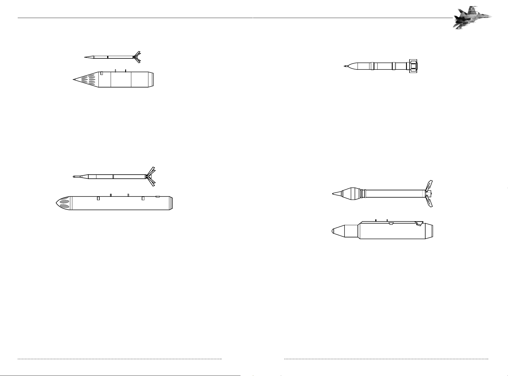
S-24 Rocket
The S-24 is a large caliber (240-mm) unguided rocket fitted with a powerful solid fuel rocket
motor. The motor operates for 1.1 seconds accelerating the rocket and providing a stabilizing spin.
The S-24 rocket can be fitted with a blast fragmentation warhead containing 23.5 kg of high
explosive. The body of the warhead is perforated and offers special induction hardening that provides very even fragmentation. After detonation, the body breaks up into 4000 fragments having
an effective radius of 300-400 meters.
The rocket is usually fitted with a proximity fuse, detonating over the target at an altitude of about
30 meters. To destroy hardened targets, the S-24 may carry a delay-after-impact fuse. The warhead housed into a strong casing pierces the covering of the target and detonates inside.
S-25 Rocket
The S-25 is a super-heavy unguided rocket housed in an expendable container. Inside its container, the rocket’s four stabilizer fins are folded between four skewed jet nozzles providing stabilization spin-up.
There are several versions of the S-25 rocket in service with varying warheads effective against
different target types. The S-25-O fitted with a fragmentation warhead and a radio proximity fuse is
effective against personnel, transport, parked aircraft, and other soft targets. The S-25-OF with a
blast fragmentation warhead destroys lightly armored vehicles, buildings, and personnel. The
S-25-OFM has a modernized strengthened penetrating warhead, which is effective against hardened facilities and warehouses, shelters and other protected targets. The S-25 has an effective
range of 2000 meters with a margin of error of about 0.3% of launch range (rockets fired at
maximum of 2000m will land within a 6m diameter).
CHAPTER 6: Air-to-Ground Weapons 125
S-8 Rocket
The S-8 is a medium-caliber, unguided rocket (80-mm in diameter) placed into the twenty-canister B-8 rocket pod. The S-8 has an effective range of 2000m. The margin of error is roughly 0.3%
of launch range; rockets fired at a range of 2000m hit within a circle of 6m in diameter. The S-8 is
normally deployed with a shaped-charge fragmentation warhead effective against soft targets.
Armor-piercing (capable of penetrating 0.8m of reinforced concrete) and fragmentation warheads
are also available. warhead
S-13 Rocket
The S-13 is a 132mm, unguided rocket placed in the five-round B-13 rocket pod. It is effective
against fortified installations and hardened facilities (fixed emplacements, bunkers, hardened aircraft shelters, and runways). These unguided rockets can be fitted with warheads of various types.
The concrete-piercing warhead can penetrate 3m of ground cover or 1m of reinforced concrete.
The S-13 has an effective range of 3000m.
The S-13T variant carries a two-stage penetrating warhead which detonates inside the target after
piercing the protective covering (up to 6m of ground cover or up to 2 m of reinforced concrete).
When the rocket hits a runway, it damages an area of about 20 square meters. The blastfragmentation warhead of the S-13OF version produces about 450 fragments weighing 25-35
grams each, effective against lightly-armored vehicles.
FLANKER 2.0
FLANKER 2.0
124 CHAPTER 6: Air-to-Ground Weapons
Page 65
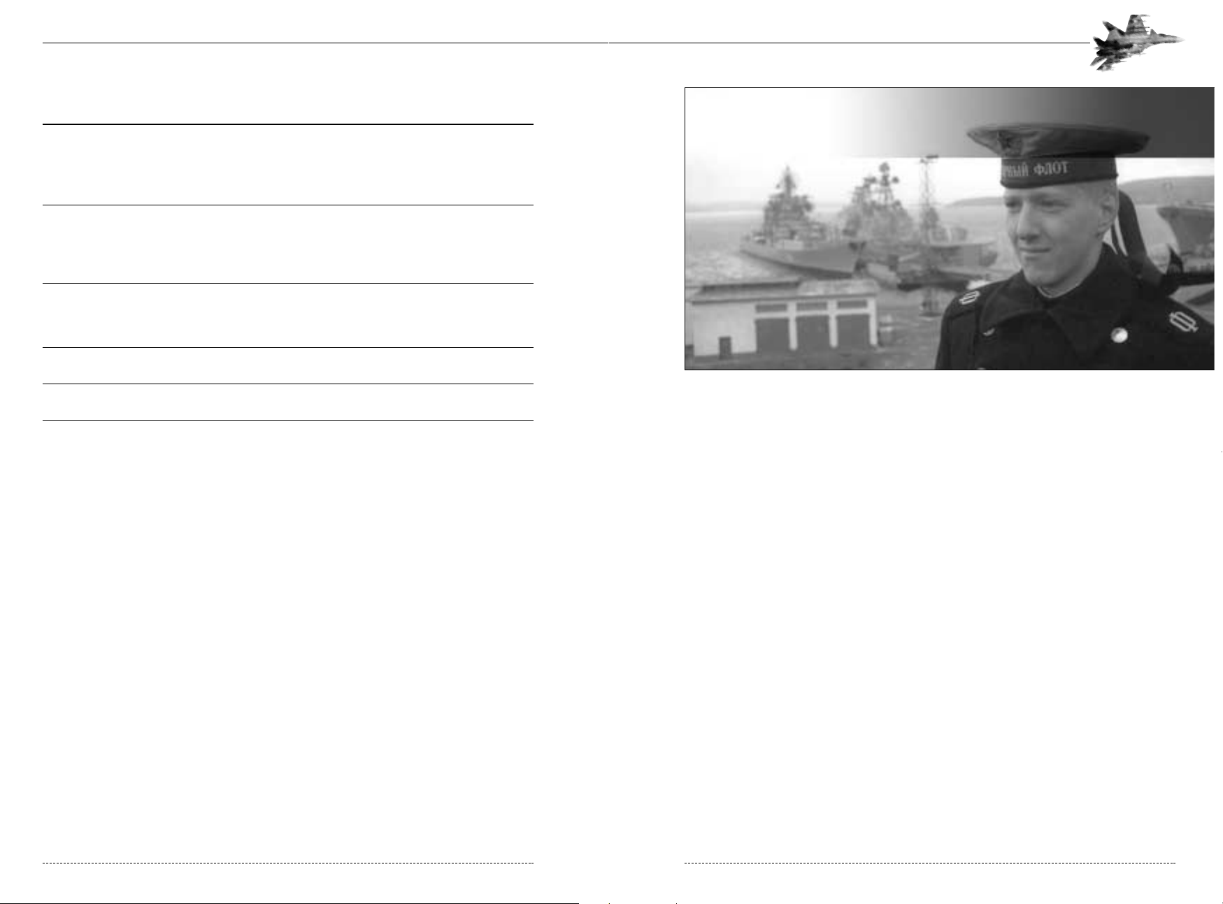
CHAPTER 7: Training Missions 127
TRAINING MISSIONS
Learning to fly a modern combat jet is no easy task. To assist you, Flanker 2.0 contains a series of
narrated training missions. Each individual mission consists of a pre-recorded track file. Playing the
track file lets you watch an experienced instructor pilot demonstrate the specific task while audibly
describing the procedure. These training missions are designed to teach you the basics on how
to successfully operate the Su-27 and Su-33 Flanker aircraft. It is by no means designed to teach
you all that you need to know about the hundreds of combinations of weapons systems, payloads
and situations you will be presented with. Reading the entire manual will allow you to become
more familiar with your aircraft and it’s capabilities.
Certain instruments and skills are covered in detail and then referred to in later training missions,
so it is advisable to go through the training missions in order. It will be assumed in later missions
that you are familiar with the workings of the controls shown in previous missions.
At a minimum, you should review the training on:
• Heads-up Display (HUD)
• Multi-Functional Display (MFD)
• Instrument Modes
• Beyond Visual Range (BVR) mode
• Searching for Surface Targets
There are additional instructions for creating your own training missions in the README.TXT file.
CHAPTER 7
Training
CHAPTER 7
Training
The table below contains specification for various types of unguided rockets:
TYPE CARRIER (#) RANGE, KM WEIGHT, KG WARHEAD TYPE
S-8B MiG-27 (80), 2.2 15.2 concrete-piercing
MiG-29 (80),
Su-24 (120),
Su-25 (160),
Su-33 (120)
S-13OF/S-13T MiG-27 (20), 2.5 68/67 blast-fragmentation/
MiG-29 (20), penetrating
Su-24 (30),
Su-25 (40),
Su-33 (30)
S-24B MiG-27 (4), 2 235 blast-fragmentation
MiG-29 (4),
Su-24 (4),
Su-25 (8)
S-25OF Su-24 (6), 3 380 blast-fragmentation
Su-33 (6)
S-25OFM Su-24 (6), 3 480 penetrating
Su-33 (6)
Cannon Straffing
The cannon is located in the starboard wing root extension and is normally used in conjunction
with the laser rangefinder. The cannon is extremely accurate, having a fire rate of 1,500 rounds per
minute, with 150 rounds ammunition. The barrel of the GSh-301 has a 2,000-round life, equivalent
to 80 seconds of fire at usual 1500 rpm. The cannon is fixed in the forward direction.
During an attack on ground targets, the cannon and unguided rockets are employed in effectively
the same way. The main differences are the maximum effective range and the minimum range
(dictated by firing safety), which for GSh-301 are 1800 and 700 meters, respectively.
FLANKER 2.0
FLANKER 2.0
126 CHAPTER 6: Air-to-Ground Weapons
Defense Visual Information Center - Department of Defense
Page 66

• The tailerons are located at the rear of the aircraft and provide the pilot with the ability to change
the angle of pitch.
• The white tailcone located between the two engine nacelles reduces drag and is used to store
the braking parachute and the chaff/flare dispenser.
• Currently moving on the back portion of the wing are the differential flaps or flaperons. These
provide extra lift for take offs and drag for landings.
• On the front edge of the wing is the leading edge flaps or slats, which are automatically driven.
These provide extra lift when manoeuvreing and during take off and landing.
• The airbrake is used to reduce airspeed quickly during manoeuvres or to reduce pitch angle on
approach and the length of the landing.
• The Flanker has 10 weapons pylons and can carry a large combination of air-to-air and air to
ground ordnance.
• The Su-33 is the naval variant of the Flanker. The most apparent difference is the canard
winglets located below and to the rear of the cockpit. The Su-33 also has folding wings, a tailhook and a 10-ton internal fuel capacity.
Heads-up Display (HUD):
This training mission will go over the basics of the Heads-Up Display. Read about the HUD in
chapter 3.
Introduction to the Instrument Panel:
This mission reviews the location of the major instruments in the cockpit. Read about the instruments in chapter 3.
Multi-Functional Display (MFD):
This mission reviews the location of the Multi-Functional Display. Read about the MFD in chapter 3.
CHAPTER 7: Training Missions 129
7-1: Training Mission Screen
While playing a training mission you may take command of the aircraft at any time by pressing ESC,
but we recommend you wait until either the instructor You may also restart the mission in order to
take control from the beginning. You may end a training mission at any time by pressing the
Control+Q keys.
The missions are divided into ten categories. Each category may contain multiple missions. Below
is a narrative of each of the training missions.
Free Flight
This section introduces you to the basics of the Flanker.
Introduction to the Flanker:
• The Su-27 Flanker is a supersonic all-weather air-superiority fighter. It has a lookdown/shootdown weapons system, complemented by beyond visual range air-to-air missiles.
• It is 72 feet in length, with a wingspan of 48 feet.
• It can reach speeds in excess of mach 2, has a range of 2100 miles and can attain an altitude of
59,000 feet.
• The Su-27 has broken a number of speed records set by the American F-15 Eagle.
• It can out-turn and accelerate faster than any variant of the F-18 Hornet in a dogfight (As reported by Inside the Pentagon, 11 Feb 99).
• The Flanker is being used in the air forces of Russia, the Ukraine, Byelorussia, Georgia, China,
India and Vietnam.
• Rudders are located on the rear part of the two vertical tailfins. These will allow the aircraft to
yaw smoothly right or left. They are also used to control the direction of movement when the aircraft is taxiing on the ground.
FLANKER 2.0
FLANKER 2.0
128 CHAPTER 7: Training Missions
Page 67
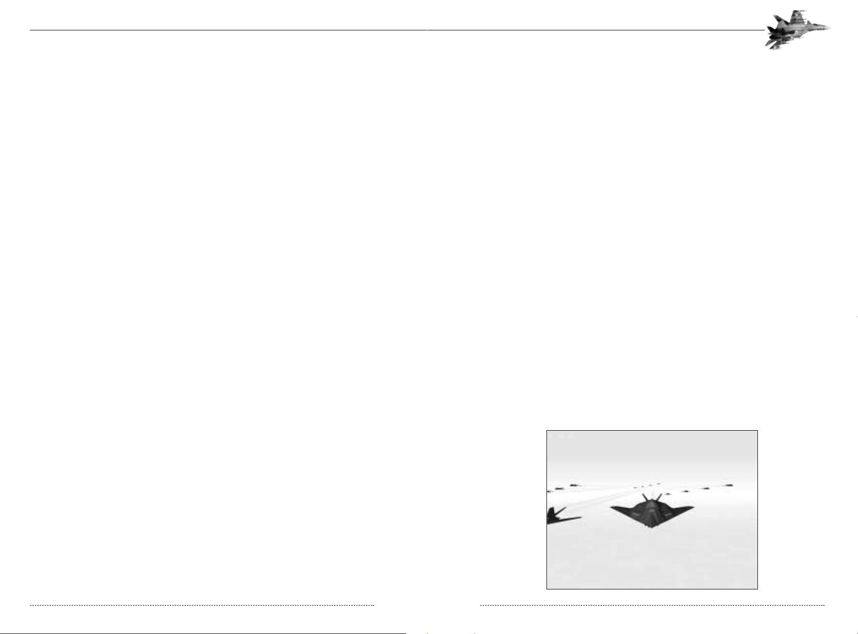
Landing
This category lets users practice landings.
Automatic Landing (with the the autoland option turned on):
This mission reviews the steps to perform an automatic landing. This mission starts out with the
aircraft currently being flown manually.
• Insure that you are in Navigation mode by selecting the 1 key.
• Turn on the autopilot by selecting the A key.
• Select the Return mode by cycling through the modes using the 1 key. This mode will be indicated in the lower left corner of the HUD.
• Look at the MFD. Select the Minus key to zoom out and view the airfield that your aircraft is to
land at. A line should be connecting your aircraft with the field.
• If you want to change airfields, use the( `) key to change the airfield you wish to land at.
• Once your aircraft has detected the approach beacon, the autopilot will change to Landing
mode. This is seen on the HUD.
• The autopilot will automatically lower your landing gear and flaps and engage the airbrake as
seen on the configuration display.
• Once your aircraft has touched down you might need to steer down the runway using the rudders. The rudder keys are Z and X. Also ensure that the throttle is at zero power by selecting
the Page Down or minus key on the number pad.
• Release the drogue chute (if you are in an Su-27) by selecting the P key. Engage the wheelbrakes by depressing the W key until the aircraft comes to a complete stop.
• Once your aircraft has touched down you will need to steer down the using the rudders. The
rudder keys are Z and X. Also ensure that the throttle is at zero power by selecting the Page
Down or minus key (-) on the number pad.
• Release the drogue chute (if you are in an Su-27) by selecting the P key. Engage the wheelbrakes by depressing the W key until the aircraft comes to a complete stop.
CHAPTER 7: Training Missions 131
Take Off
These missions start the user on the ground, ready for takeoff.
Light Takeoff:
This mission reviews the steps to perform a light take-off. A light payload is a takeoff weight of
less than 22,000 kilograms.
• Engage the wheel brakes by holding down the W key.
• Missions start with the engine already on. Increase throttle to full military power by pressing the
Page Up key or the Plus key on your number pad until the RPM gauge reaches 100%.
• At 100% power, release the wheel brakes with the W key.
• Move straight down the runway. If necessary, use your rudders to steer. The rudder keys are the
Z and X keys.
• At a speed of 250 kilometers, rotate by pulling back smoothly on the stick.
• Raise the gear when the altimeter shows a positive rate of climb by selecting the G key. If you
do not raise the gear, an audio reminder will sound.
Heavy Takeoff:
This mission reviews the steps to perform a heavy take-off. A heavy payload is a takeoff weight of
more than 28,000 kilograms.
• A heavy payload is a takeoff weight of more than 28,000 kilograms.
• Engage the wheel brakes by holding down the W key.
• To engage the flaps you would select the F key. The configuration display will show green below
the aircraft figure when they are engaged.
• Missions start with the engine already on. Increase throttle to full military power by pressing the
Page Up key or the Plus key on your number pad until the RPM gauge reaches 100%.
• At 100% power, release the wheel brakes.
• Increase power to maximum afterburner.
• Move straight down the runway. If necessary, use your rudders to steer. The rudder keys are the
Z and X keys.
• At a speed of 280 kilometers, rotate by pulling back smoothly on the stick.
• Raise the gear when the altimeter shows a positive rate of climb by selecting the G key. If you
do not raise the gear, an audio reminder will sound.
• When the altitude reaches 100 meters, raise the flaps by selecting the F key.
FLANKER 2.0
FLANKER 2.0
130 CHAPTER 7: Training Missions
Page 68
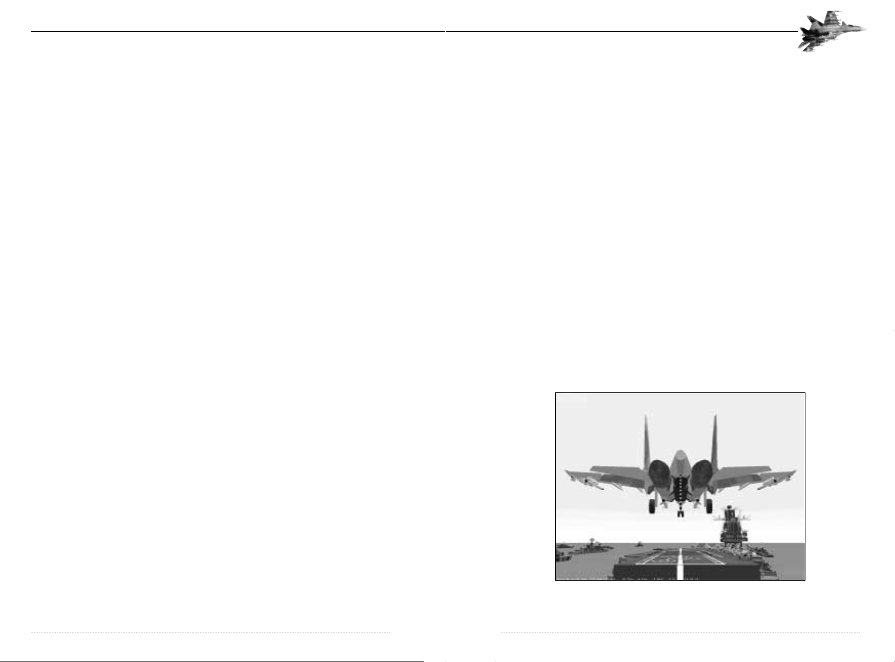
• As the nose goes past 70∞ nose up, return the stick to neutral.
• With the aircraft returning to level flight, add power as the nose comes to 30∞ pitch up angle.
Stalls and Spins
Learn how to recognize, avoid, and recover from dangerous stalls and spins.
Recovery from Spins and Stalls
In order to stay airborne an aircraft must produce enough lift. Flying at low airspeeds or high
angles of attack may prevent the aircraft from generating enough lift and this may result in a stall.
Coarse use of bank input or rudder at high angles of attack may result in a spin. If you experience
a spin at an altitude of less than 2000 meters, eject immediately, as recovery is highly unlikely.
• Once you notice that the aircraft responds badly and the angle of attack is high, place the stick
and the rudders in the neutral position and wait for the angle of attack to start to drop.
• If the aircraft starts to yaw and enters a spin, counter it by pressing the rudder pedal of the
opposite direction. Slightly push the stick forward and throttle back to idle.
• If this does not work, push the stick farther forward and continue the opposite rudder.
• If the spin does not stop within 5-6 seconds, deflect the stick in the direction of the spin.
• If this does not help and your altitude is less than 1500 meters eject!
• As the rotation slows, release the rudder pedals and the stick to the neutral position at once.
Any delay may result in a spin in the opposite direction.
• After you gain control of the aircraft, wait until it has reached a speed of at least 350 kilometers
per hour, then power up and level off.
CHAPTER 7: Training Missions 133
Aerobatics
These missions allow you to practice standard manoeuvres.
Roll
• While maintaining an airspeed of 400 to 800 kilometers per hour, smoothly pull back on the stick
until you have a nose up pitch angle of about 13 degrees.
• Deflect the stick to the desired direction of rotation, keeping a rate of rotation of about 60
degrees per second.
• Recover the wings level and pitch angle of about zero degrees.
Loop
• Ensure that your airspeed is between 600 and 900 kilometers per hour and your wings are level.
• Increase your throttle to full military power and pull back to a pitch angle of about 70 degrees.
• As you go past vertical, try to maintain a 15 degree angle of attack.
• Also correct any bank that developed during the ascending part of the manoeuvre.
• Look for the horizon. As it goes past, throttle back to 100% or less.
Half Loop
The half-loop is an excellent way to change direction and gain altitude.
• Ensure that your airspeed is between 600 and 900 kilometers per hour and your wings are level.
• Increase your throttle to full military power and pull back to a pitch angle of about 70 degrees.
• As you go past vertical, try to maintain an angle of attack of 15 degrees
• At the upper most point relax the stick to neutral and execute a half roll.
• Ensure that your angle of pitch is around zero degrees.
Reverse Turn
The reverse turn or Split-S is an excellent way to change direction quickly, while losing altitude. Do
not try this manoeuvre unless you start at an altitude of at least 3000 meters.
• At an airspeed of between 400 and 900 kilometers per hour execute a half roll. Be sure to
check the horizon.
• Smoothly pull back on the stick until you are flying level again.
Pugachev’s Cobra
In this manoeuvre the Flanker is pulled to a high angle of attack and then returned to horizontal
flight within 3-4 seconds. This causes an intensive loss of airspeed.
• Ensure that you have an airspeed of 350-450 kilometers per hour with the engine RPMs at 75%.
• Take the angle of attack and G limiter offline by selecting the K key.
• Pull back on the stick sharply to a pitch angle of 105 degrees and maintain it for about 3 seconds.
FLANKER 2.0
FLANKER 2.0
132 CHAPTER 7: Training Missions
Page 69
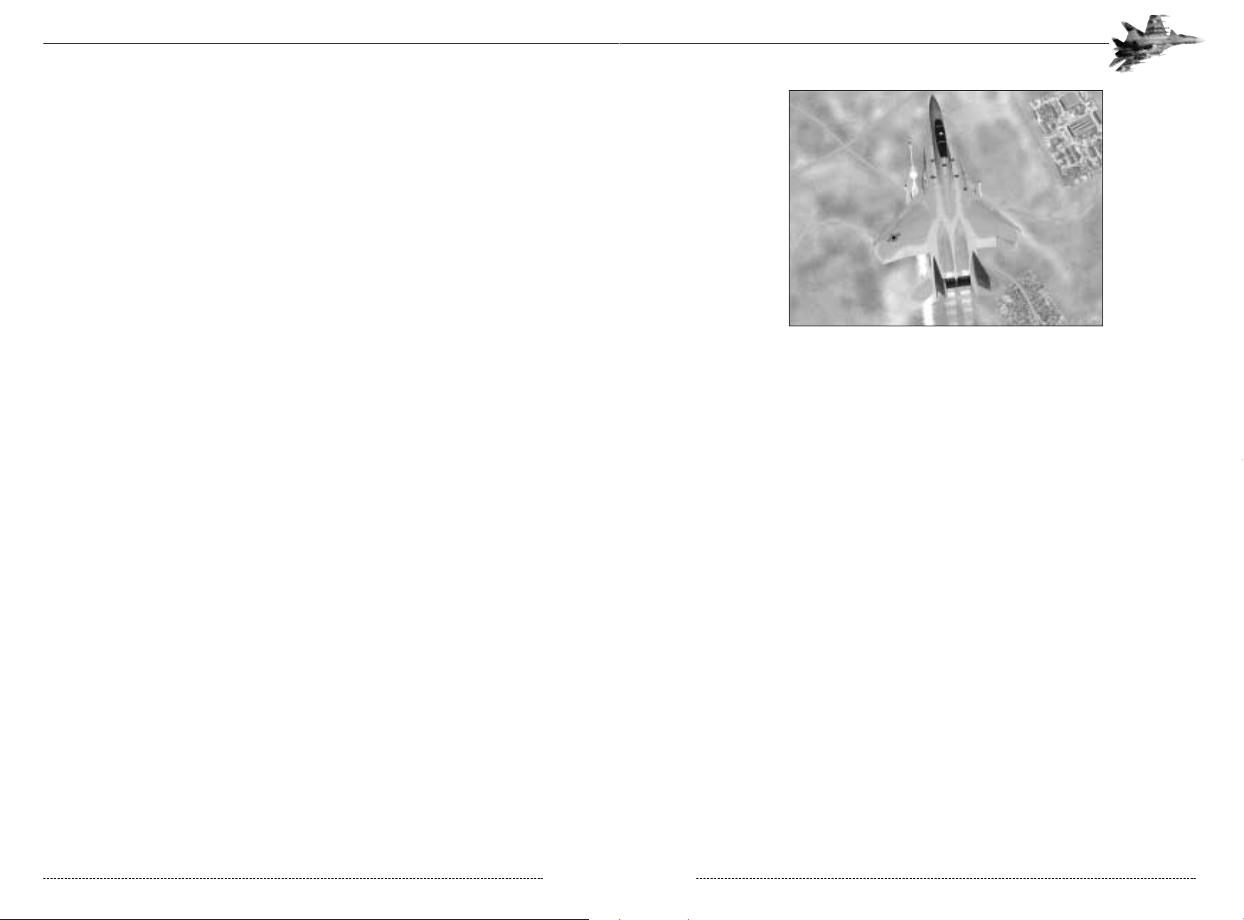
Air-to-Air
Basic Air Combat Modes
Beyond Visual Range (BVR) mode:
The BVR mode is used to acquire and engage targets at ranges of 25 to 150 kilometers.
• Press the 2 key to select this mode.
• Ensure that the radar is on. An “I” should appear on the left side of the HUD.
• You will see a box in the middle of the HUD that is your designator. You can use this to individually select targets to track or to lock on to.
• On the right of the HUD are 4 vertical lines. You will see them lighting up in sequence. This
shows what vertical area your radar is currently scanning.
• Objects that your radar detects will appear as dashes on the HUD.
• You may cycle through the onboard weapons by selecting the D key.
• On the MFD you will see a cone that represents your radar coverage.
• The radar is in scan mode. Press the 2 key again to select the track while scan sub-mode. The
weapons control system will automatically select the closest and fastest 8 scan contacts. These
contacts will appear as triangles on the HUD.
• To lock onto a target, move the designator using the scan zone controls and select the Tab key.
The vertical scan controls are the semi-colon (;) and period (.) period keys. The horizontal controls are the comma and forward slash keys.
• You will see the heading and velocity of the selected target.
• Once you have a launch authorized cue (LA) on your HUD, you may shoot.
• After your target has been destroyed, the system will revert to the scan mode.
• To unlock from a target press the TAB key again.
CHAPTER 7: Training Missions 135
Carrier
Practice basic carrier operations with your Su-33.
Carrier Take-Off
• To engage the flaps you would select the F key. The configuration display will show green below
the aircraft figure when they are engaged.
• Increase the throttle to afterburner. By pressing the Page Up key or the Plus (+) key on your
number pad.
• Rotate by smoothly pulling back on the stick.
• Raise the gear when altimeter shows a positive rate of climb by selecting the G key. If you do
not raise the gear, an audio reminder will sound.
• When the altitude reaches 100 meters, raise the flaps by selecting the F key.
Automatic Carrier Landing
This mission reviews the steps to perform an automatic carrier landing. This mission starts out
with the aircraft currently being flown manually.
• Ensure that you are in Navigation mode by selecting the 1 key.
• Turn on the autopilot by selecting the A key.
• Select the Return mode by cycling through the modes using the 1 key. This mode will be indicated in the lower left corner of the HUD.
• Look at the MFD. Select the Minus key to zoom out and view the carrier that your aircraft is to
land at.
• A line should be connecting your aircraft with the carrier.
• If the line connects you to another landing location, use the ` key to cycle through the landing
locations until the carrier is selected.
• Once your aircraft has detected the approach beacon, the autopilot will change to Landing
mode. This is seen on the HUD.
• The autopilot will automatically lower your landing gear, arrestor hook, flaps and engage the
airbrake as seen on the configuration display.
• The number in the lower center of the HUD is the distance to the carrier in kilometers.
FLANKER 2.0
FLANKER 2.0
134 CHAPTER 7: Training Missions
Page 70

Longitudinal Aiming Mode:
The longitudinal aiming mode is used to acquire and engage visual targets using the seeker on a
missile. Press the 6 key to select this mode.
• A circle will appear in the center of the HUD. Your objective is to manoeuvre your aircraft to
place the target in that circle. To lock onto a target, select the TAB key.
• Once you have a launch authorized cue (LA) on your HUD, you may shoot.
• To unlock from a target select the TAB key again.
Air-to-Ground
This category shows you how to find surface targets.
Searching for surface targets:
• Press the 7 key to select the Air to Ground mode.
• Press the “I” key to turn the radar on.
• A diamond will appear on the HUD. The diamond is the radar target designator, which shows
where your radar is aimed. The circle is the Continuous Computed Impact Point or CCIP.
• Your task is to acquire and lock onto the target with your radar and then place the CCIP on the
diamond by manoeuvreing your aircraft.
• You may cycle through the onboard weapons by selecting the D key.
• The MFD is in scan mode. Use the vertical control keys to move the scan zone up and down.
The vertical scan controls are the semi-colon (;) and period (.) keys.
• Notice that the diamond is moving on the HUD.
• Once you are in the general vicinity of the target, go to the Wide Search mode by selecting
the + key.
• Continue to search for the target with both the vertical and the horizontal scan controls. The horizontal controls are the comma (,) and forward slash (/) keys.
• Once you have the surface target in the box on the MFD, select the + key again to go to the
Narrow Search mode.
• To lock onto a target, select the TAB key.
• Now manoeuvre your aircraft to place the CCIP over the diamond on the HUD.
• Ensure that you are in range using the range scale on the HUD.
• Once you have a launch authorized cue (LA) on your HUD, you may shoot.
• You have acquired the target. There are many different weapons that can be used in the Air to
Ground mode, so please familiarize yourself with each weapon’s abilities.
• To unlock from a target select the TAB key again.
CHAPTER 7: Training Missions 137
Close Air Combat (CAC) mode:
The CAC mode is used to acquire and engage visual targets at ranges of 25 kilometers or less.
• Press the 3 key to select this mode. A band will appear in the center of the HUD. Your objective
is to manoeuvre your aircraft to place the target in that band.
• You may cycle through the onboard weapons by selecting the D key.
• You can move the band side to side with the comma (,) and forward slash (/)keys.
• To lock onto a target, select the TAB key.
• Once you have a launch authorized cue (LA) on your HUD, you may shoot.
• The C key toggles your cannon on and off. Once the target is in gun range, a target reticle
will appear. Manoeuvre your aircraft so that the crosshairs line up with the target.
• To unlock from a target select the TAB key again.
Helmet Mode:
The Helmet mode is used to acquire and engage visual targets using the aiming reticule on
your helmet.
• Press the 5 key to select this mode. A thick circle will appear in the center of the HUD. Using
the number pad keys, you can move this circle onto a target.
• You may cycle through the onboard weapons by selecting the key.
• To lock onto a target, select the TAB key.
• Once you have a launch authorized cue (LA) on your HUD, you may shoot.
• To unlock from a target select the TAB key again.
Bore Site Mode:
The Radar Bore Site mode is used to acquire and engage visual targets at ranges of 25 kilometers
or less.
• Press the 4 key to select this mode. A circle will appear in the center of the HUD. Your objective
is to manoeuvre your aircraft to place the target in that band.
• You may also move the Bore circle using the scan controls. The vertical scan controls are the
semi-colon (;) and period (.) keys. The horizontal controls are the comma (,) and forward
slash (/) keys.
• You may cycle through the onboard weapons by selecting the D key.
• To lock onto a target, select the TAB key.
• Once you have a launch authorized cue (LA) on your HUD, you may shoot.
• To unlock from a target select the TAB key again.
FLANKER 2.0
FLANKER 2.0
136 CHAPTER 7: Training Missions
Page 71
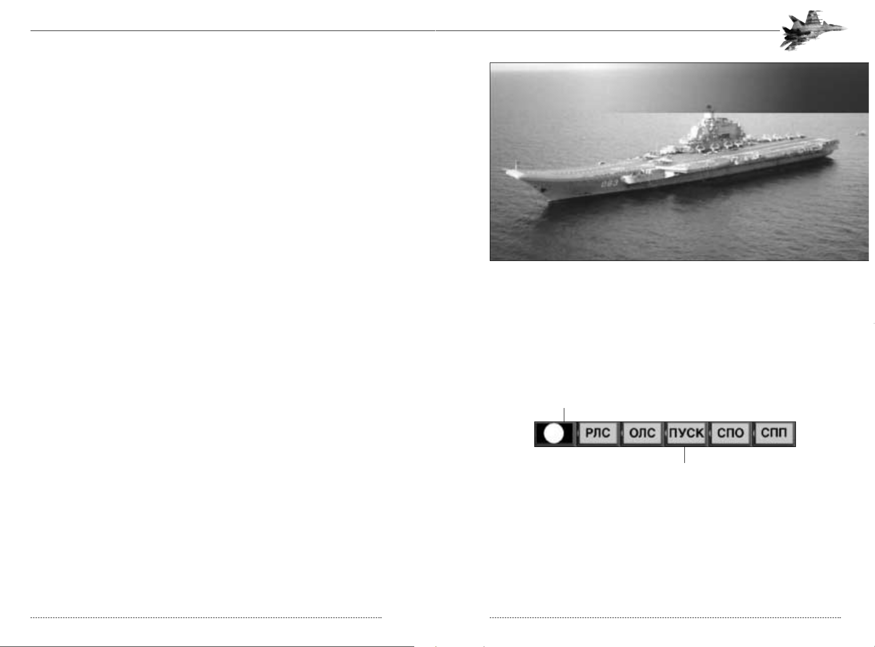
CHAPTER 8: Master Warning System 139
Onboard warning systems call your attention to battle damage, system malfunctions, enemy
threats, or other dangerous situations. Correct interpretation of warning signals may save your
aircraft, or at least save your life by providing sufficient time to eject.
MASTER WARNING SYSTEM
The Master Warning System (MSW) is designed to attract your attention to a specific failure. A
Master Warning Light will flash and an alarm tone will draw your attention to the instrument panel.
The MWS indicates that one of the following has occurred:
• Impact with the ground is imminent – Accompanied by an “X” symbol on the HUD, your current
flight path will result in a collision. The light flashes at 1 Hz and emits an audible alarm. Pull up
immediately.
• Low fuel – The MWS light flashes at 1 Hz and is accompanied by an alarm beep for 10 seconds.
The red NJGKBDJ light on the fuel gauge also illuminates. Land as soon as possible.
Master Warning Light
Missile Launch Warning
CHAPTER 8
Emergency Procedures
CHAPTER 8
Emergency Procedures
Anti-Ship
Learn the basics for successfully attacking ships.
Anti-Ship:
• Selecting the 7 key will place you in the Air to Ground mode. This is the mode that is used to
engage ships.
• Selecting the I key to turns the radar on.
• The MFD is in scan mode. Use the vertical control keys to move the scan zone up and down.
The vertical scan controls are the semi-colon (;) and period (.) keys.
• Notice that the diamond is moving on the HUD.
• Once you are in the general vicinity of the target, go to the Wide Search mode by selecting the +key.
• Continue to search for the target with both the vertical and the horizontal scan controls. The
horizontal controls are the comma (,) and forward slash (/) keys.
• Once you have the surface target in the box on the MFD, select the + key again to go to the
Narrow Search mode.
• You will now see that there are crosshairs in the MFD. Once you have moved the crosshairs
over the target select the Tab key to lock in on the target.
• Once you have a launch authorized cue (LA) on your HUD, you may shoot.
• To unlock from a target select the TAB key again.
Anti-Radar
Practice destroying hostile radar sites with this mission.
Anti-Radar:
• The Threat Warning System senses a SAM radar, manoeuvre your aircraft towards the general
direction of the source.
• Press the 7 key to select the Air to Ground mode.
• You may cycle through the onboard weapons by selecting the D key.
• To lock onto a target, select the TAB key.
• If the SAM’s radar is strong enough, and the missile’s range parameters are met, you should get
the launch authorized (LA) on your HUD.
• Once you have the launch authorized cue (LA) on your HUD, you may shoot.
• To unlock from a target select the TAB key again.
See the README.TXT file for instructions on creating your own training missions.
FLANKER 2.0
FLANKER 2.0
138 CHAPTER 7: Training Missions
Defense Visual Information Center - Department of Defense
Page 72

All Russian aircraft are equipped with an Identification Friend or Foe (IFF) system, allowing the
RWS to distinguish between friendly and hostile radar sources. This system also replies to friendly
emitters, alerting them that you’re not a hostile target.
MISSILE LAUNCH WARNING SYSTEM
The infrared MLWS detects the hot emissions produced by incoming missiles. A totally passive
system, it watches for the type of heat produced by solid-propellant rocket motors. Its effective
range varies depending on the intensity of the heat emission, but can generally spot inbound
missiles up to 15 km away.
When the MLWS detects an inbound missile, the GECR symbol (meaning “launch” in Russian)
illuminates and produces a warning beep at 2 Hz for five seconds. The MLS light also illuminates.
After five seconds the audio alarm silences, but the warning light remains on until the system
loses contact with the missile.
h When the MLWS illuminates, take evasive action immediately!
The voice messaging system also provides audible cues indicating where the missile is coming
from. The system will announce “Missile at…” followed by a clock position such as “12 high”
or “6 low.”
CHAPTER 8: Missile Launch Warning System 141
• Landing gear is still deployed at a high airspeed – The warning light flashes at 1Hz and is
accompanied by a warning beep. Both alarms cease when you retract the landing gear.
• Some onboard equipment has failed or taken battle damage – Check the instrument panel for
individual warnings or failure indicators, such as a failed engine, failed hydraulic system, or malfunctioning radar. See later sections for more information on handling specific failures.
• Your aircraft is being painted by enemy radar – The MWS flashes at 5 Hz when the RWS detects
enemy emissions. Flashing changes to 1 Hz when a lock-on has been detected. Check the
threat warning display in the lower right corner of the instrument panel. Take evasive action as
appropriate.
• The Missile Launch Warning System has detected an inbound missile – The MWS light is
accompanied by the Missile Launch Warning light. Take evasive action immediately.
To reset the MWS, press the shift + M key.
RADAR WARNING SYSTEM
The SPO-15 “Beryoza” Radar Warning System (RWS) detects enemy radar signals and operates
like any radar detector used in automobiles to locate police radar. Thanks to a more complicated
antenna system (fitted in the tailcone) and more processing power, the RWS not only detects
radar, but also indicates the bearing to the transmitter and the type of radar detected. A totally
passive system, it merely listens for other’s emissions. This system is used in a variety of Russian
aircraft including the MiG-29 Fulcrum , MiG-31 Foxhound, and Mi24P Hind.
The ten lights surrounding the MiG-21 picture illuminate to indicate the bearing to the transmiter.
A flashing light indicates your aircraft is being painted occasionally by the emitter. A solid light
indicates that a transmitter is tracking your aircraft. A red light surrounding the silhouette indicates a lock onto your aircraft. The six lights along the bottom of the RWS correspond, from left to
right, to five categories of radar signals:
• Airborne radar
• Short-ranged SAM
• Medium-ranged SAM
• Long-ranged SAM
• Early warning radar
• AWACS
FLANKER 2.0
FLANKER 2.0
140 CHAPTER 8: Radar Warning System
Threat Bearing Indicators
Radar Type Indicators
Lock-On Detected
Page 73
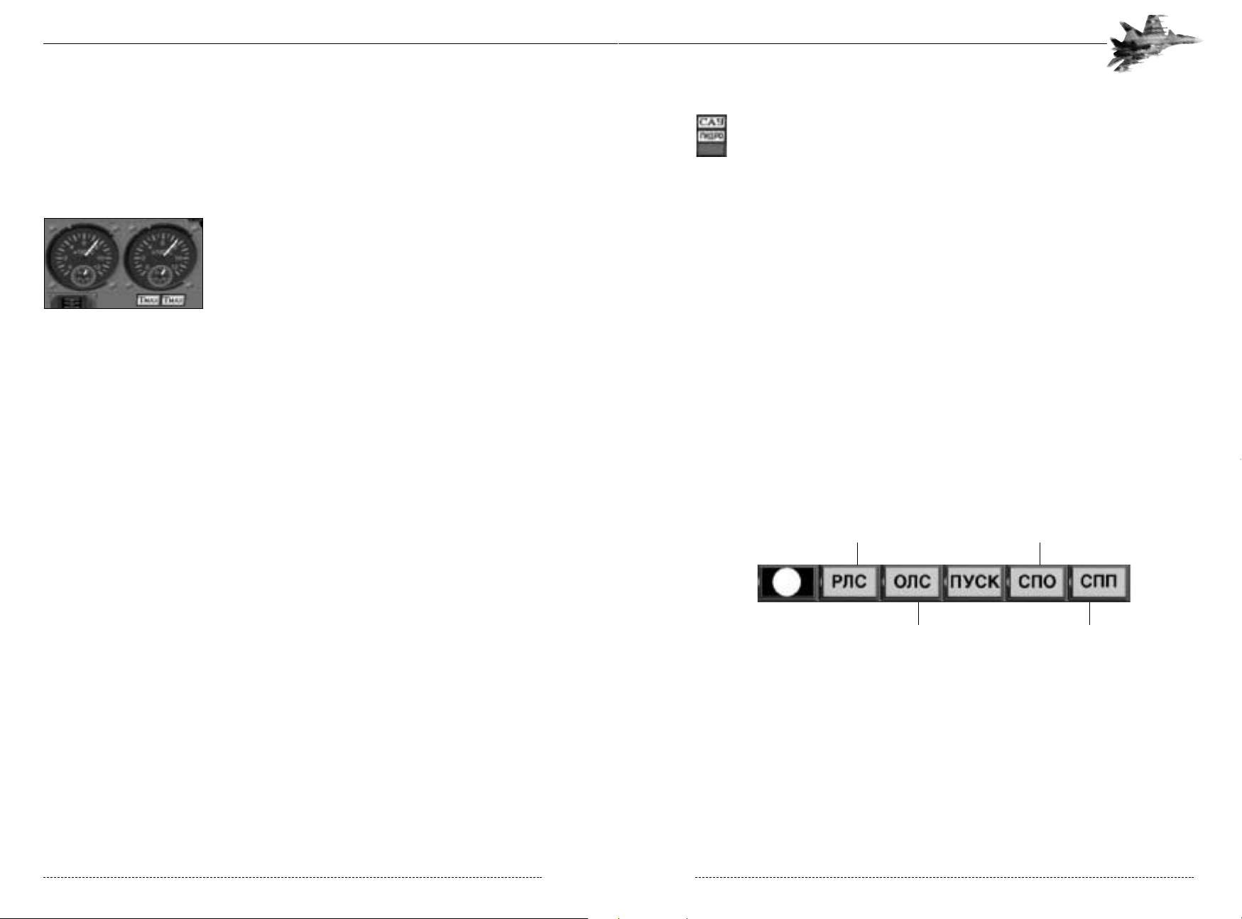
Flight Control System Failure
The flight control system can suffer three types of failures:
• Hydraulic System Failure – Indicated by the UBLHJ warning light, this kind of failure results in
loss of control of flaperons, slats and the airbrake along with reduced aileron and rudder authority.
• Automatic Control System (ACS) Failure – Indicated by the CFE warning light, this type of failure
renders the autopilot and the Altitude Stabilization mode inoperable. You must disable any automatic flight mode and assume manual control of the aircraft.
• Automatic Control Regulation System Failure – Also indicated by the CFE warning light, this
failure switched the Flight Control System to “rigid link” operation. In this backup mode of operation, the FCS computer applies proportional control: moving the stick a certain percentage of total
travel moves the control surfaces the same percentage of their maximum movement. The aircraft
becomes very unstable at slow speeds and reacts badly to stick movements at high speeds.
Disable the autopilot if necessary and assume manual flight control. Maintain forward airspeed
of 500 to 600 km/hr and head for the nearest airbase. Fly the approach at 400 km/hr and touchdown at 270 km/hr.
Special Systems
Individual instruments may also be damaged. The most common items to take damage are the
HUD, the MFD, the Radar, RWS, and MLWS. Most of these failures are indicated on the MWS
caution lights. If any of these systems fail, they will be unusable for the remainder of the mission.
Other Failures
If the pitot head is damaged, the airspeed indicator and the barometric altimeter will display
erroneous results. The ACS may be erratic, engine RPM may drop, and forward airspeed
may decrease.
If the ECM system fails you will have no active jamming system for the remainder of the mission.
The Helmet Mounted Target Designation (HMTD) may also be damaged. The Targeting circle
disappears and you will be unable to designate targets in Helmet mode.
CHAPTER 8: System Failures 143
SYSTEM FAILURES
Eventually, all mechanical items, even modern, high-tech jet fighters, eventually break down especially when constantly exposed to enemy fire. Knowing how to respond to common failures will
help you bring a damaged jet home safely. The MWS monitors many of the aircraft systems. The
system can’t monitor every aspect of the aircraft, but it will alert you when it detects a malfunction.
Engine failure
Engine failures are commonly caused by missile hits. Typically,
the damaged engine shows an increased jet pipe temperature coupled with a loss of RPM. When the temperature
increases beyond the permissible threshold, the corresponding Maximum Jet Pipe Temperature (TMAX) indicator illuminates. When this happens, fire extinguishers automatically
deploy and the damaged engine automatically shuts down.
Single Engine Failure
It is possible to fly the Flanker on a single engine. Because the engines are not aligned with the
aircraft’s centerline, though, the offset thrust of a single engine will cause the nose to roll or yaw in
the direction of the bad engine, especially at higher thrust levels. A heavy aircraft will be more difficult to control, especially with asymmetric stores. Try jettisoning unnecessary fuel and weapons.
In all cases, center the slip ball using the rudder and trim the aircraft.
If the nose of the aircraft begins to roll uncontrollably toward the bad engine, quickly reduce
power and apply more opposite rudder. For example, if the left engine dies, the aircraft may try to
roll to the left. Reduce power and apply right rudder to stop the roll.
It is quite possible to land the aircraft on a single engine, but fine use of the rudder is required. The
asymmetric thrust will complete alignment and you’ll need to use the rudders to keep the aircraft
pointed down the runway. Also remember that you only have 50% as much thrust. If you get a little
too low or too slow during the approach you won’t have the power available to correct the situation. Try flying a little higher than the normal approach path to give yourself more margin for error.
Dual Engine Failure
If both engines fail, the Flanker becomes a very expensive and very heavy glider. Immediately jettison all ordnance and fuel. In such circumstances, ejection is preferred over trying to ditch the aircraft; however, if you have sufficient altitude you may wish to glide back to friendly territory before
ejecting . As a rule, you can generally glide one to two kilometers for each 1,000 meters of altitude. For example, a Flanker at 3,000 meters should be able to glide 3 to 6 km.
FLANKER 2.0
FLANKER 2.0
142 CHAPTER 8: System Failures
Radar Failure RWS Failure
MLWS FailureEOS Failure
Page 74

CHAPTER 9: Strategy and Tactics Overview 145
STRATEGY AND TACTICS OVERVIEW
Modern technology has completely revolutionized the battlefield in less than a century. Aircraft in
particular have advanced from little more than motor-powered kites to modern combat jets in just
a few decades. Defense contractors and military officials often cite the strengths of their vehicles,
but rarely mention the major shortcomings in public. Consequently, many people develop an opinion that aircraft (and other battlefield platforms) are more capable than they really are.
The primary reason flight simulator pilots get shot down is inappropriate usage of their platform.
Keep in mind that surface-to-air defenses and enemy aircraft have made the same technological
leaps. True, today’s aircraft are significantly more powerful and survivable than their WWII counterparts; at the same time, enemy gunfire is much more accurate, powerful, and able to fire at longer
ranges. In short, the battlefield is a more dangerous place than ever before.
UNDERSTANDING ENEMY AIR DEFENSES
Enemy air defenses, including surface-to-air missiles and anti-aircraft artillery are an integral part of
the modern battlefield. Interlinked defense nets let defense sites across the battlefield communicate and share information. Pilots must possess a thorough knowledge of (and a strong respect
for) such systems, or they’ll find themselves riding a parachute with alarming frequency.
AAA
In general, Anti-Aircraft Artillery (AAA) is effective against low-flying targets and mainly serves for
covering troops from enemy aircraft. Many armies have multi-barreled mobile AAA systems fitted
with radar and a fire control system that provide effective operation in any meteorological conditions. In distinction to Ground Forces, ship-borne artillery usually has a multipurpose character and
fighting against airborne targets is just one of their several functions.
CHAPTER 9
Tactics
CHAPTER 9
Tactics
Defense Visual Information Center - Department of Defense
Page 75

9-x: A Typical Defense Network
If the SAM itself can track the target, it measures and processes the parameters of the target’s
motion and sends them to the control post through radio data link. The coordinates of the SAM
itself are measured by a ground-based tracking radar. Again, after comparing the coordinates of
the SAM and of the target, the control post sends guidance commands to the SAM. Long-range
SAM systems such as the S-300 (SA-10B ‘’Grumble’) usually employ this type of command guidance in mid-course.
9-Y: Command guidance sends course updates to the missile.
CHAPTER 9: Understanding Enemy Air Defense 147
An AAA shell consists of a warhead, an impact fuse that detonates at the moment of contact with
the target, and a “time fuse” which detonates after a particular flight time. The target is generally
destroyed by the fragments produced by the warhead on detonation.
Land-based systems, like the ZSU-23-4 Shilka (pronounced ‘shil-ka’) employ mutli-barreled cannons, off-road mobility, and high rate of fire. Usually equipped with its own radar, self-propelled
AAA usually has some backup aiming method, such as an IR or optical seeker.
To destroy low-flying airborne targets, combat ships use multipurpose guns that can also be used
against enemy ships and coastal defense. For the most part, shipborne artillery is classed as 100
to 130-mm guns (heavy caliber), 57 to 76-mm guns (medium caliber) and 20 to 40-mm guns
(small caliber). All guns have a high degree of automation of aiming, loading, and firing. Automatic
small-caliber (20-40 mm) anti-aircraft guns are mainly effective against low-flying aircraft and
cruise missiles. Since SAMs normally have a substantial minimum range (within which airborne
targets cannot be hit) ship-borne AAA is used as a short-ranged, point defense weapon. Firing
around 1,000 rpm per barrel, such weapons create a nearly impenetrable cloud of metal between
the target and the ship. Such 30-mm guns have an effective range of 5,000 meters; however,
range is less important than rate and density of fire.
SAMs
Surface-to-air missiles (SAMs) form the backbone of the air defense network, integrating each
individual search and track sensor with every unit on that network. Short-ranged, Man Portable Air
Defense Systems (MANPADS) carried by infantry troops fill any gaps.
The main elements of a SAM (airframe, guidance system, fuse, warhead, and rocket motor) are
similar in design and functions to those of AAMs. In addition, some SAMs utilize exhaust-deflector
vanes for additional manoeuvreability.
The flight trajectory of a SAM, as well as the composition and principle of operation of the autopilot are governed by the guidance method employed. The autopilot on its own or with the help of
ground facilities continuously calculates relative positions of the SAM and the target and provides
commands to the control surfaces. Guidance for SAMs can be classified as one of the following:
command, semi-active beam-rider guidance, homing and combined guidance.
Command guidance
Command guidance may be compared to classic remote control. During the SAM’s flight the positions of both the target and the missile are monitored from the ground or by the missile’s onboard
equipment.
If a SAM is guided by the ground facilities (see the figure below), the latter are responsible for
detecting the target, measuring its coordinates and those of the SAM. After processing the coordinates the control post forms encoded guidance instructions and transmits them to the missile by
radio data link, which is susceptible to jamming. After decoding by the missile’s onboard equipment the commands are sent to the autopilot. This type of command guidance is normally
employed in short-range and medium-range SAM systems (such as the SA-15 and SA-8) since
the guidance accuracy decreases as the range increases.
FLANKER 2.0
FLANKER 2.0
146 CHAPTER 9: Understanding Enemy Air Defense
Page 76

Combined guidance
As the name implies, some missiles combine guidance methods to improve performance. The Kub
(Cube) SAM system (SA-6A ‘Gainful’) is an example of a system with combined guidance. This
system employs radio command guidance on the initial part of the missile trajectory and homing
when closing in on the target. This provides high accuracy at long range.
SAM engagement envelope
Like air-to-air missiles, SAMs have specific engagement envelopes. Firing at targets within the
heart of the envelope increases the likelihood of a hit. Just like air-to-air missiles, the envelope
varies based on the target’s range, altitude, and aspect. In the engagement diagram shown, the
area defined by the numbers 1, 2, 3, 4, and 5 represent the missile’s effective area. Note that this
envelope shifts if the target is moving toward the launcher, in the area defined as a, b, c, d, e. In
this case, the missile must be fired at longer range since the target will fly part of the way into the
missile. If the missile is fired too late (once the target has crossed the a, b, c line), it pass out of
the envelope before the missile arrives.
Caption 9-x: Typical SAM engagement envelope.
The position of the upper and right boundaries of the envelope mainly depends on the energy
capabilities of the SAM and quality of its tracking system. This boundary defines the altitude and
range to the collision point providing engagement effectiveness not less than a given threshold.
Since the SAM trajectory depends on target speed, altitude, and course, the position of the envelope boundary is calculated for a particular given speed of the target.
Maximum effective range of the tracking system is governed by the target’s radar cross section (or
effective reflection area) and altitude and varies substantially against different sized targets. If for a
certain target the effective range of the radar is less than that of the SAM, this will decrease the
engagement envelope. SAMs are generally classified based on their range as:
CHAPTER 9: Understanding Enemy Air Defense 149
Beam-rider guidance
Semi-active, beam-rider guidance is somewhat similar to command guidance along the line of
sight between the target and the tracking radar, except that the missile guidance system is
designed to seek and follow the center of the guidance beam automatically, without specific
correction instructions from the launching platform. The guidance beam is provided by a groundbased target tracking radar, and “highlights” the direction to the target. Like command guidance
systems, beam-rider SAM systems are not limited to daylight and good-weather conditions.
9-y: Beam Riding missiles follow the guidance beam to the target.
One problem with beam-rider systems, as with command ones, is that the SAM must have high
manoeuvreability in order to intercept an evasive target. As they approach the target, beam-rider
missiles often must tighten their turns continually to keep up. Using two radars, one for target
tracking and a second for missile tracking and guidance, can reduce this problem somewhat by
providing a more efficient lead trajectory. Beam-rider guidance is usually more accurate and fasterreacting than command guidance systems.
Homing
The most effective type of guidance against evasive targets is homing, when the missile guidance
system gets information about the target and produces control commands on its own. Thus, the
control post does not guide the SAM.
For active homing the SAM illuminates the target and receives the signals reflected off the target.
In the case of semi-active homing, the source of illumination (tracking radar) is located at the control post, and the SAM receives signals reflected from the target. Passive homing systems use heat
or light emitted by the target to estimate the parameters of the target’s motion.
In general, homing systems operate in the following way: while the SAM rests on the launcher its
seeker is locked onto the selected target, the parameters of the target’s motion being measured.
After launch the SAM seeker tracks the target, estimating the tracking error and produces control
commands independently from the ground.
FLANKER 2.0
FLANKER 2.0
148 CHAPTER 9: Understanding Enemy Air Defense
Page 77

COUNTERING AGAINST ENEMY AIR DEFENSES
Successfully penetrating the enemy air defense network is difficult . The following suggestions will
help you punch through, engage the target, and make it safely home again.
Don’t Get Shot At
It may seem rather obvious, but the best way to avoid being hit by a missile is by preventing the
enemy from ever launching one. Fighter jets are often portrayed as modern knights roaming the
skies in search of a duel, but are in actuality more like cats. Skillful hunters and powerful killers,
they try to slip by silent and unseen while stalking unsuspecting prey. Try to avoid enemy air
defense concentrations when ever possible. If possible, flight paths should be routed toward
known weak spots or other areas which have been heavily attacked.
Further, don’t wander from the instructed flight path. Other aircraft and ground forces will usually
be working to keep a corridor open for you. Straying out of this corridor and into enemy SAM
traps is usually fatal and is a common problem for simulation pilots.
Suppresion of Enemy Air Defenses
The Su-27, being rather large, isn’t particularly stealthy. The pilot, therefore, must rely on tactics to
mask his presence from the enemy. Perhaps the most effective way of preventing the enemy from
firing is simply to shoot first. This generally means detecting the bad guys early, making a discreet
approach, firing first and getting out fast. By launching a fire-and-forget anti-radar missile, such as
the Kh-31p, the targeted SAM is forced to switch off its own radar to have any chance of surviving. In air-to-ground terms, strike forces should generally be accompanied by a SEAD escort; two
or more aircraft equipped to engage enemy air defenses and radar sites.
Low Level Flight
Caption: Figure 9-x: A typical hi-low-hi ingress profile.
Such a brute force, kick-them-in-the-teeth approach may not always be possible. There may not
be sufficient aircraft available or the enemy may have taken out friendly GCI radars. In this case,
terrain masking may be the best choice. As the name implies, pilots fly extremely low (as low as
30m above the ground in some cases) using hills, mountains, and other landscape features to
CHAPTER 9: Countering Against Enemy Air Defense 151
• Long-range (> 100 km).
• Medium-range (20 to 100 km).
• Medium-and-short range (10 to 20 km).
• Short-range (< 10 km).
The position of the lower boundary of the engagement envelope depends on the radar’s ability to
detect and track low-flying targets and on the ability of the SAM to fly at low altitude without
crashing into the ground. Besides, the proximity fuse should not mistakenly detonate near the
ground by confusing the latter with a target.
Many factors such as curvature of the ground surface, reflection of radio waves from the ground,
and ground clutter, limit the possibility of detecting a low-flying target. Ground curvature limits the
line-of-sight range, which affects operation of long-range and medium-range SAMs. Indeed, if a
radar antenna is located at ground level, then the radio horizon dip is about 20 metres at a distance
of 20 km and 150 metres at a distance of 50 km. The dip of the radio horizon increases proportionally with the square of distance. This means that it will be impossible to detect a target flying at an
altitude of less than 150 metres while at a distance of 50 km. Lowering the radar beam will not help
as it will only create further ground reflected interference which further reduces range.
The figure below shows a typical antenna radiation diagram as a function of distance and altitude.
Furthermore, at low altitudes it is relatively difficult for radar to discriminate between target returns
and returns from local objects such as towers, moving heavy goods vehicles, etc. Reflection intensity of local objects may vary depending on their material, size, shape, surface smoothness, etc.
Consequently, returns from local objects depend on the specific operating conditions of the radar.
These returns may lead to errors of measurement of angular position and range to the target,
which will adversely affect the quality of guidance and may break the target lock.
To aim a SAM at a certain point, most SAM launchers are equipped with horizontal (for azimuth
angles) and vertical (for elevation angles) mechanisms. Such SAM launchers are called rotary.
This makes it possible to launch the SAM in the optimal direction therewith reducing an initial vectoring error and bringing the near boundary of the SAM envelope closer. Modern SAM systems
also use vertical launchers which permit simultaneous multi-direction launches.
The Defense Network
Modern military forces link their early warning and tracking radars via an interlinked network.
This allows one search (or tracking) radar to share data with every other user on the same network. Consequently, the SAM launcher may not have to transmit from it’s own radar, instead
relying on guidance from other tracking devices located elsewhere on the net. It may appear that
all enemy radar sites are located several kilometers ahead of you, but you may be directly over
the enemy launcher!
“Blinking,” whereby different tracking radars on the network take turns tracking the target and
guiding the inbound missile is a very common practice. No one radar stays on long enough for
your forces to counterattack, and the heading of the radar warning continually changes on your
radar warning receiver. When caught in such a SAM trap, you must visually locate the incoming
missiles, take the appropriate evasive manoeuvres described later in this chapter, and get out of
the trap as quickly as possible.
FLANKER 2.0
FLANKER 2.0
150 CHAPTER 9: Understanding Enemy Air Defense
Page 78

Evading Missiles
Missiles are tough opponents, they are in general 2-3 times faster, can pull 3-4 times mores G
than you and are small and hard to track visually. Successfully evading a missile depends on many
factors such as how quickly you detect the missile and how deep you are within the weapon’s
launch envelope. Depending on the circumstances, you have several evasive manoeuvres to
choose from; choose the wrong one and the missile, quite literally, will follow you for the rest of
your simulated life.
In Chapter 6 we discussed the air-to-air missile envelope and how factors like range, airspeed,
and altitude of the target and launcher impact that envelope. Fortunately (for the target aircraft),
missiles are bound by the same laws of physics as the aircraft they chase. That is, despite having
much more power available than aircraft, they bleed speed in a turn just like a fighter and missile
turn rate and turn radius performance depend on the missile’s overall energy state. The trick to
defeating missiles, therefore, is making it run out of energy before it gets to you.
Launch Warnings
Launch warnings come from a variety of sources. In some circumstances, a wingman might see
the launch and issue an appropriate warning over the radio. In some cases, your radar warning
receiver might indicate the enemy is tracking you. In most cases, though, the best indication of an
inbound missile is visual detection. When in hostile territory, constantly scan the area around you
for puffs of smoke (indicating a launch) or long smoke trails which extend behind most missiles
while the motor burns. Remember to scan the ground as well as the sky as these indicators may
betray a SAM launch as well as an air-to-air launch.
Keep in mind that once the missile’s motor burns out it will stop producing a smoke trail, so early
detection is critical. Long-ranged air-to-air missiles generally climb to high altitude, then dive on
the target, so be especially alert for rainbow-shaped smoke trails coming toward you!
Knowledge Is Power
Your first weapon is knowledge—knowledge about your enemy’s capabilities and his position. For
example, assume that an U.S.-built AMRAAM has a nominal range of 45km at 5,000m. You’ve
conducted a thorough radar sweep of the area ahead of you and are certain that the only targets
around are a pair of F-15s about 40km away. Suddenly, you see the tell-tale smoke trails of
inbound missiles. Since you know these missiles were fired near maximum range, you can probably out-run them. Execute a corner-speed, turn 180 degrees away, then unload to 1g, and accelerate directly away by diving at 30-45 degrees at full afterburner.
Success depends primarily on how quickly the target can turn (a clean fighter may be able to pull
a 9g turn, a heavily laden jet may be limited to 5g) and how quickly it can accelerate after that
turn. If you receive warning of the launch soon enough, you stand a good chance of out-running
the missile. If you’re late picking up the missile or the target waits until you’re deep in the launch
zone before firing, this method probably won’t work.
CHAPTER 9: Countering Against Enemy Air Defense 153
remain discreet. All tactical detection systems rely on line-of-sight between the sensor and the target. Laser, radar, optical, and IR detection and tracking systems cannot penetrate hills and other
such obstacles. Such nap-of-the-earth (NOE) flight is very effective, but is also very dangerous. At
high speed and low altitude, the slightest mistake can result in an immediate crash. Also, AAA
units will generally be placed to protect low-level ingress routes to high-value targets, further
increasing the hazards of flying low. This type of tactical flying will not be effective against modern
AWACS tracking, but will keep you clear of most AAA and SAM risk.
Figure 9-x: The affects of target altitude on radar propagation. Flying high (left)
increases chance of detection as opposed to flying low (right).
AAA Counter Measures
AAA systems generally cannot engage targets above 1,500 meters above them. That does not
necessarily mean that flying 1,501 meters above sea level renders you immune to AAA. The
enemy will often place AAA on hilltops or ridgelines, thus increasing their effective altitude.
Generally, the best way to evade AAA is to simply climb above it. Inside its engagement envelope,
however, AAA is deadly. When AAA fire suddenly erupts around you, always remember:
1. Be unpredictable. Any erratic jinking manoeuvres will help disrupt the AAA’s fire control computers.
2. Don’t waste energy. Each time you pull the stick to manoeuvre you bleed energy and airspeed.
Keep weaving, but don’t slow down.
3. Don’t fly in circles. Make your turns erratic and unpredictable. Whatever you do, keep flying
along a general course that takes you away from the AAA. Don’t fly circles above it.
If you’re near its effective altitude limit, you might be able to engage afterburners and quickly climb
above it. This, however, poses two potential problems. First, you’ll present a nice, easy target while
climbing. Second, by increasing altitude you increase the likelihood of being detected by other air
defenses or aircraft.
FLANKER 2.0
FLANKER 2.0
152 CHAPTER 9: Countering Against Enemy Air Defense
Page 79

the missile directly on your 3/9 line, pull just enough g-load to keep it there. The missile has a limited field of view, much like the beam of light emitted from a flashlight. If you pull a continuous 9g
turn in the middle of that “beam,” the “flashlight” will fly up to, and then punch a hole through,
your aircraft.
Instead, you want to fly toward the edge of the beam, known as the gimbal limit moving as fast as
possible across the missile’s field of view. By manoeuvreing to the edge of its field of view you
force it to make the largest corrective manoeuvres. In the best case, you might move out of its field
of view, in the worst case you make the missile bleed as much energy as possible. Keeping the
missile directly on the 3/9 line also points your hot engine exhaust away from an IR missile’s seeker. Beaming may also present problems for Doppler radar systems, although remember that you’re
beaming the missile, not the launching platform.
Like the aforementioned flashlight beam, the missile’s field of view grows wider at longer range.
Consequently, at long range you’ll pull minimum g. As the missile gets closer, you increase the gload as necessary to keep it stationary on your 3/9 line. If the missile appears to move toward your
nose, you’re pulling too much g and basically turning inside the missile’s field of view.
h If the missile doesn’t make constant corrective actions after you begin beaming,
it probably is tracking someone else.
Be sure to release chaff and flares while maintaining this turn, especially as the missile gets closer.
If you start too early, the missile will not be spoofed. Each press of the Q key release one chaff
(effective against radar-guided missiles) and two flares (effective against heat-seeking missiles)
from the APP-50 dispenser in the tail boom. The system releases both since pilots rarely know
exactly which type of missile is approaching. These decoys may present a more attractive target in
the middle of the seeker’s field of view. The missile may turn toward them, allowing you to pass
out of it’s field of view. Modern missiles are fairly smart, though, and can often tell the difference
between a quickly-decelerating bundle of chaff and your aircraft.
Figure 9-x How chaff/flares spoof missiles.
CHAPTER 9: Countering Against Enemy Air Defense 155
Fight Missiles With Aspect
Most modern missiles fly lead as opposed to pure-pursuit paths to the target. That means each
time the target changes course, the missile changes course as well. A lead-pursuit missile will
attempt to hold a constant lead angle enroute to the target and appear to remain stable on your
canopy relative to the horizon. A pure-pursuit missile will appear to remain pointed directly at you,
but it’s position will drift back toward the back of your aircraft. For the most part, if the missile
appears in a relatively constant position while steadily growing larger, it’s successfully tracking
your aircraft. If the missile appears to be rapidly moving across your canopy, it’s probably going to
miss you (or is tracking somebody else).
h If missile appears stationary on the canopy while growing steadily larger, it is
probably on intercept course. If it’s rapidly moving across the canopy, it probably
won’t hit you.
Since missiles, like aircraft, need energy to manoeuvre and bleed speed while manoeuvreing, you
want to make the missile manoeuvre as much as possible. The more you manoeuvre, the more
work the missile must perform and the more energy it will bleed trying to adjust to your manoeuvres. This forces the missile to fly a curved path to the target, bleeding speed and energy along
the way.
Beaming an inbound missile.
Begin by “beaming” the target; that is, executing a corner-speed, turn toward the missile to place
it exactly 90 degrees off your nose (to either your 3 o’clock or 9 o’clock position). Once you have
FLANKER 2.0
FLANKER 2.0
154 CHAPTER 9: Countering Against Enemy Air Defense
Page 80

jamming environment, though, presents a formidable obstacle to inbound missiles. The key to survival, though, is early detection of enemy missiles. The earlier you see the missile, the more time
you have to defeat it.
AIR-TO-AIR TACTICS
The Su-27 was built as an air superiority fighter. Despite the addition of air-to-ground ordnance
(especially on the Su-33), the air-to-air is a primary part of the Flanker’s mission. The main goal of
air-to-air engagements usually isn’t to let the situation degrade into a dogfight. Especially for interceptor aircraft like the Flanker, the goal is to engage enemy aircraft at long range before the
enemy can counter attack. Ideally, the enemy aircraft are destroyed, but merely forcing them to
abort their mission is often sufficient. In military terms, this latter case is called a “mission kill.”
Searching For Targets
The Su-27 carries a very powerful radar, but can only provide weapons tracking information against
one target at a time. The Su-33, however, can provide weapon targeting and launch solutions for
two targets simultaneously. Ideally, long-ranged counter-air missions should always include
AWACS support. With AWACS information datalinked directly to the Flanker, enemy aircraft will be
painted on the MFD even if the Flanker’s radar is inactive. Keeping the Flanker’s radar deactivated
reduces the chances of being detected by enemy aircraft (remember, enemy aircraft can detect
your radar transmissions about two times farther away than the your radar can detect that aircraft).
Use AWACS data (or other datalinked radar information) to trap or ambush the enemy.
If AWACS isn’t available, then the aircraft assigned to the mission must conduct their own air
searches. Keeping in mind the limitations of the scan cone, flight leaders should order formations
that allow effective searches of wide areas. Two aircraft flying close, finger-tip formation effectively
limits both aircraft.. Horizontal separation lets two aircraft search a wider area; vertical separation
lets them search a taller area.
Vertical and horizontal spacing also complicates the enemy’s ability to track and detect friendly aircraft. Enemy search radars on fighter aircraft also have limited scan cones. Widely spacing friendly
aircraft may keep some of them outside the enemy scan cone. Further, this aircraft is free to
manoeuvre while the enemy focuses attention on the detected aircraft. The second aircraft can
manoeuvre around and engage the enemy from its flank or rear while the first aircraft lures the
enemy fighters into the trap.
When forced to conduct your own long-ranged searches, keep in mind that the radar cross section
(RCS) of the target determines how far away the Flanker’s radar will detect it. Large bombers will
generally be detected much farther away than tactical aircraft. Also, ground clutter generally helps
mask targets. Consequently, lower-altitude targets usually can’t be detected at longer ranges.
Manoeuvres
While the goal of any interceptor is to engage with long-ranged missiles and escape, dogfights
inevitably erupt.
h Air combat is not a chess game. Pilots do not use specific manoeuvres to
CHAPTER 9: Countering Against Enemy Air Defense 157
Flying a steady flight path followed by a high-g break turn at the last second before missile impact
probably won’t work. When the missile realizes it’s overshooting the target, it will detonate and
(depending on the missile’s blast radius) seriously damage your aircraft. Instead, make the missile
work all the way and give it a generous number of chaff/flare decoys to sort through.
h Don’t fly into your own decoy. Although the decoy will drift somewhat, it remains
relatively stationary compared to the speed of your jet. If you continue a steady turn
after releasing chaff/flares, you’ll eventually fly full circle, right back around to it.
Since you’re trying to spoof the missile, put as much distance between you and the
decoy as possible. Also, after firing a flare, disengage afterburner if practicable.
This will make the flare appear an even bright and better target than your aircraft.
Jamming
ECMActive jamming, also called Electronic Counter Measures (ECM) is designed to confuse
inbound missiles by presenting them with false radar information. Jamming attempts to transmit
signals in the appropriate frequency band which overpower and mask the normal radar returns
reflected by the target. If the radar source closes on the target, it will eventually reach “burn
through” range, at which point the reflected energy from the target is stronger than the false signals sent from its ECM gear.
The ECM gear doesn’t actually make the missile go madly off into the wild blue yonder. Instead, it
generally increases the distance between the missile and the target when the missile detonates.
By sending false signals, the ECM gear may make the missile think it’s closer than it actually is. By
manipulating the frequency of the false signals, it can create false Doppler shifts, further confusing
the missile.
Consequently, we can see that the jamming equipment must be specifically tuned for the threat at
hand. Broadcasting high power across a wide spectrum is relatively difficult; therefore, the jamming equipment is usually configured to defeat the threats most likely to appear during a given
mission. Consequently, successful jamming depends on intelligence gathering equipment to
ensure the ECM gear is operating in the appropriate frequency ranges. Multiple jammers should
be used if a wide variety of threats are anticipated.
Jamming has one drawback: it announces its presence to everyone for miles around. Imagine
someone shouting at the top of their voice during a business meeting. The loud noise prevents
other attendees from communicating but also draws attention to the screamer. Likewise, jamming
may block the immediate threat, but also draws attention.
The Flanker normally carries a built-in ECM pack, providing defense against airborne and groundbased radars. The status of the jammer is indicated by the AG indicator on the instrument panel.
The aircraft can also carry the Sorbtsiya-S ECM system (roughly similar to the U.S.-built AN/ALQ135 jammer), which is installed in two pods on the aircraft wingtips. It can detect and recognize
illumination sources and jam that frequency. If the enemy radar shuts down, the system automatically ceases jamming.
The Whole Package
In general, no one system (manoeuvreing, decoys, and jamming) is sufficient to spoof an incoming
missile 100% of the time. Correctly combing appropriate manoeuvres with well timed decoys in a
FLANKER 2.0
FLANKER 2.0
156 CHAPTER 9: Countering Against Enemy Air Defense
Page 81

Based on this scenario, we see that the range to the target is arguably the most important aspect
of aerial gunnery. The further away the target is, the longer the bullets fly. Consequently, the
shooter must lead the target more and account for greater drop due to gravity. As most WWII
pilots (who did not have the benefit of pickling off a guided missile) discovered, don’t shoot until
the enemy aircraft fills the view. The closer you are, the more likely you’ll hit something. Deflection
shooting, or the art of appropriate leading a manoeuvreing target, increases in difficulty as range
to target increases.
h Aerial gunnery can be summarized in three steps:
1. Match the target’s wings.
2. Pull lead.
3. Shoot
Tracking Shots vs Shots of Opportunity
A tracking shot refers to a relatively slow, methodical approach to the target, achieving a stabilized
firing position, and shooting the target. The shot of opportunity, on the other hand, refers to the
brief moment when a target aircraft suddenly (and perhaps unpredictably) crosses your nose. You
have mere moments to react, but a quick burst of gunfire is likely to score hit if fired in time.
Whereas opportunity shots rely primarily on your reflexes; tracking shots require more finesse. In
particular, you generally need to be in the same two-dimensional plane of motion as the target.
This is defined by two vectors, the forward velocity (or longitudinal axis) and the lift vector (which
is perpendicular to the wings). Although a good deflection shooter, especially equipped with a
CHAPTER 9: Countering Against Enemy Air Defense 159
“counter” enemy movements. Air combat is a fluid, dynamic, constantly changing
environment. Rather than thinking “he did a split-S, so I’ll counter with a high yoyo,” pilots instead consider where they need to point their aircraft in order to
employ their weapons. They then execute the appropriate manoeuvre to adjust their
lift vector and bring their aircraft into a firing position.
The Break Turn
The most basic, defensive manoeuvre is the break turn. In this case, the pilot turns toward the
threat aircraft to increase aspect angle and ruin the opponent’s firing solution. Generally speaking,
a break turn indicates a maximum-performance turn, using all available instantaneous g.
As an attacker, if the target executes a defensive break turn, you will generally resort to the high
yo-yo to prevent overshooting.
The High Yo-Yo
The high yo-yo uses a relatively quick movement out of the target’s plane of motion to either slow
closure rate or to reduce aspect angle to the target. The high yo-yo is performed by rolling slightly
behind and above the target,extending behind the target’s flight path for a moment, then rolling
back toward and pulling the nose down to the target. The high yo-yo generally increases the
range to the target, but decreases the aspect angle, setting up an firing opportunity. The length of
time between rolling away from the target until pulling back into the target determines how “big”
the yo-yo is. Generally speaking, executing a series of small yo-yo’s to slowly nibble away at a
large angular problem is better than executing one large manoeuvre.
If you have an adversary executing high yo-yo’s behind you in order to gain a firing position,
watch the enemy’s nose closely. Your movement away from him helps solve his closure rate or
aspect angle problem. Whenever his nose comes off (that is, is pointed behind your flight path),
relax your turn and accelerate, thus increasing your energy status. As his nose pulls back into firing position, increase the g-load and tighten your turn. Conserve your energy when his nose is off,
spend your energy as he brings his nose toward a firing position.
Aerial Gunnery
Firing a gun from a moving platform and trying to hit another moving platform executing evasive
manoeuvres is no trivial task. To begin with, the bullets take a finite amount of time to leave the
barrel and travel to the target; the further away the target is the longer each projectile takes to
cover the distance. During that time of flight, the target will probably execute some form of evasive
manoeuvre; he probably won’t be in the projectile’s flight path by the time it gets there. So, the
shooter has to “lead” the target; predict where it will be by the time the bullets get there and then
fire at that point hoping the target flies into the projectile stream. Meanwhile, gravity tugs on the
projectiles, pulling them toward the ground. The farther and slower the projectile flies, the more
the bullets drop. The shooter must factor this drop into the lead calculations as well.
Meanwhile, the shooter is moving also. Since he’s chasing the target, he’s probably flying a curved
flight path. Consequently, his tracer stream appears to “bend” away since the individual rounds
continue on a straight flight path. If all goes according to plan, the shooter aims ahead of the target, fires, and watches the tracers appear to fly a curved path to intercept the target.
FLANKER 2.0
FLANKER 2.0
158 CHAPTER 9: Countering Against Enemy Air Defense
Page 82

and-forget antiship missiles equipped with sophisticated inertial + active radar combined guidance
systems (Kh-41, Kh-35, Kh-31a). After the launch, the missile flies to the vicinity of the initial coordinates, switches on its onboard seeker, and searches for the target.
The second guidance method is called “command guidance.” The Kh-59m, for example, uses
command guidance. Prior to launch, the radar locks on to a specific ground target. After the missile is launched, the radar transmits guidance commands to the missile, steering it to the target.
This system is relatively inexpensive and is very effective against stationary targets. Of course, the
launching aircraft must maintain a radar lock on the ground target until the missile strikes. This
could leave the launching aircraft vulnerable to counter attack.
Passive guidance systems comprise the third guidance type, encompassing several types of missiles. Whereas command guided missiles receive specific course instructions, passively guided
missiles home in either on the emissions produced by the target (heat, or radar) or by energy
(light) reflected by the target. The Kh-29te, for example, uses either IR (heat) or TV (light) tracking systems, homing in on the energy emitted by (or reflected from) the target. The Kh-31p,
meanwhile, homes in on radar energy emitted by the target. Such systems do not rely on the
Flanker’s onboard radar for guidance, but the individual missile’s seeker , to search for, to select
and to engage targets.
THE MISSILE GUIDANCE SYSTEM
TYPE OF MISSILE MISSION GUIDANCE SYSTEM GETS INITIAL DATA FROM: “FIRE-AND-FORGET”
Kh-35, Kh-31a, Antiship Inertial + active radar Flanker Radar YES (for all three)
Kh-41
Kh-31p Antiship, antiradar Passive radar Missile Seeker YES
Kh-29te Pinpoint strike, IR (or TV) Missile Seeker YES
Antiship
Kh-59m Pinpoint strtike Command Flanker Radar NO
Using tactical missiles.
Su-33 can carry two tactical missiles: Kh-29te with IR or TV seeker, effective against fortifications,
major railway and highway bridges, launchers, ships, surfaced submarines, etc. and Kh-59m longrange tactical missile with command guidance system, which can be used against static ground
objects (buildings, bridges, etc.).
Kh-29te
After selecting the Kh-29, the MFD displays information supplied by either the missile’s onboard
seeker or, if selected,the aircraft’s radar. While it may be useful to use the radar to initially locate
your target, you should always disable the radar and ensure the missile’s onboard seeker is tracking the target before launching the weapon.
CHAPTER 9: Air-To-Ground 161
modern HUD and “shoot” cues, may be able to achieve the appropriate lead, but manoeuvreing
in-plane with the target aircraft greatly increases your chances of scoring a hit.
How do you manoeuvre into the target’s plane of motion? By matching the target’s wings. You
can obtain a high-percentage tracking shot by manoeuvreing behind the target, matching the
bank angle of the target’s wings, then pulling sufficient lead based on the range to the target.
When executed properly, the target should fly straight into the “bending” stream of your tracers.
Using Air-to-Air Missiles
Air-to-Air missiles are relatively easy to use. Once you’ve locked a target, select the desired weapon.
If the target is within acceptable launch parameters, the GH (LA) “shoot” cue will appear on the bottom of the HUD. Firing a missile at a target near the missile’s maximum range greatly reduces the
chances of hitting; the less distance the missile has to fly the greater the chance of it hitting the target. When the target is within range and the “shoot” cue is displayed, release the weapon.
Remember that SARH missiles require a continuous radar lock for the duration of the missile flight.
If using SARH missiles, be careful to maintain radar lock until the missile reaches its target.
AIR-TO-GROUND
The methods of using air-to-ground weapons greatly depend on their type. However, there are
some common ways of interpreting the commands of the Weapons Control System and using
weapons against ground or water surface targets:
1. Make sure that the Weapons Control System and the HUD are in the A2G Mode as shown by the
PTVKZ designation on the HUD Mode Indicator (if not, press 7).
2. Choose optimal weapons for the planned target by cycling through onboard weapons (press the D
key). To toggle the cannon, hit the C key. The selected type of weapon and its remaining quantity will
be shown on the lower part of the HUD. The Weapon Readiness Panel illuminates the pylons carrying
the selected weapon.
3. Place the Aiming Reticle on the visual target or the cross-hairs on the target’s image on the MFD by
manoeuvreing your aircraft.
4. After you place the target in the sight, lock onto it to provide targeting information for the selected
weapon or just fire (depending on the weapon used).
5. Select Salvo mode if you want to fire unguided rockets from all available pods or release all bombs
simultaneously. To toggle Salvo mode, use the Ctrl+V keys. If this mode is active the weapons type and
quantity symbology on the HUD are enclosed in a rectangle.
6. If the selected weapon requires that specific conditions for range or other parameters should be met,
you have to wait until the GH Shoot Cue appears on the HUD and only then start firing.
Missile Guidance Techniques
The Su-33 can use a wide variety of air-to-surface missiles, including antiship (Kh-31a, Kh-41,
Kh-35), tactical (Kh-29te, Kh-59m) and antiradar (Kh–31p). The missiles have different guidance
systems and interact with the WCS and radar in different ways.
In the first case the radar enters all the initial information about the target (coordinates, speed,
etc.) into the missile’s guidance system prior to launch. This method is commonly used with fire-
FLANKER 2.0
FLANKER 2.0
160 CHAPTER 9: Air-To-Ground
Page 83
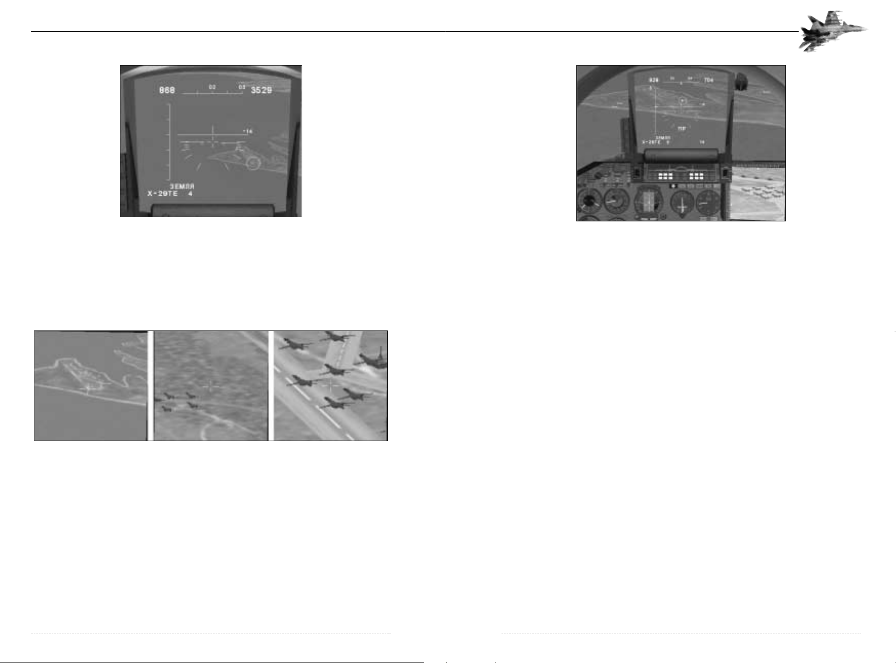
HUD Symbology For A Locked Kh-29te
The HUD now shows a range-to-target scale along the left hand side as well as the missile’s
time-of-flight along the lower edge. When you’ve manoeuvreed within the missile’s launch envelope, the HUD displays the launch indicator. Try to move the aiming reticle near the center of the
HUD before firing the missile. This helps ensure the missile will not lose the lock on the target.
Once the missile is released you’re free to manoeuvre and/or engage other targets.
Kh-59m
Functionally, using the Kh-59m is similar to firing a Kh-29te. The Kh-59, however, uses command
guidance meaning:
1. You must use the Flanker’s radar to locate and lock the target
2. You must not break the radar lock until the missile strikes the target.
Begin the process by activating the ground radar. Using scan mode, SWA mode, and SNA mode,
locate the desired target. Lock the target by pressing TAB. Manoeuvre toward the target until the
shoot cue appears, then launch the missile. The autotrack indicator will begin flashing, denoting
you have a missile inflight under data transmission guidance. Maintain the radar lock until the
missile hits.
CHAPTER 9: Air-To-Ground 163
The Kh-29 Aiming Reticle
When using the Kh-29te, an aiming reticle appears in the HUD, indicating where the missile’s
onboard seeker is looking. Steering the seeker head with the scan zone controls moves the aiming
reticle around the HUD. The MFD displays the view seen by the missile’s seeker. The seeker provides three levels of magnification, 2x, 8x, and 32x. Adjust the magnification displayed on the MFD
up and down using the + and – keys.
Comparing MFD Magnifications: 2x, 8x, and 32x.
By steering the seeker and manoeuvreing your aircraft, place the aiming reticle over the target.
Increase magnification, if necessary, to help identify the target. Lock the seeker to the object by
pressing TAB. The MFD view now stays focused on the locked object and the aiming reticle tracks
the object’s position. You may lock the target using any magnification level. To break the lock,
press the TAB key again.
FLANKER 2.0
FLANKER 2.0
162 CHAPTER 9: Air-To-Ground
Page 84
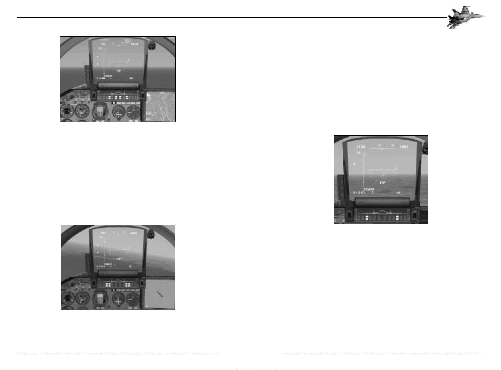
Using Antiradar Missiles.
Antiradar missiles home in on the radar emissions of ground and sea-based transmitters, such as
early warning radars, SAM guidance radars, and air traffic control radars. The Kh-31p antiradar
missile can engage all types of SAM radar systems without requiring the launching aircraft to
enter the SAMs launch zone.
Target detection begins with the SPO-15 RWS detecting an emission source. This system illuminates the appropriate lights on the TWD, trips the master warning. Steer the aircraft to bring the
desired target directly ahead of your nose. Lock the target by pressing TAB . Manoeuvre toward
the target (fly toward the marker on the HUD) until the shoot cue appears. After firing, the
weapon system drops the lock and you’re free to manoeuvre and/or engage other targets.
After locking the missile to the radar emitter, the HUD switches to autotrack mode, displaying the
usual information on range and missile flight time.
Antiradar HUD Symbology
The Kh-31p is launched when it is comfortable with the strength of the radar signal from the emitting vehicle. As the missile flies towards the target, it sharpens the exact location of the target, giving it the possibility to calculate the target’s ground coordinates. This means that should the target
radar be switched off prior to impact, the Kh-31p would still have a chance of hitting the target.
If the range to the target is less than the Kh-31p’s minimum launch range, the reject cue appears
on the HUD and the you cannot fire the missile.
Firing Unguided Rockets and The Cannon
You may engage ground targets with unguided rockets or the onboard cannon. Both weapons are
relatively short ranged and less accurate than tactical missiles. Begin the attack by switching to
air-to-ground mode and selecting the desired weapon. Using scan, SWA, and SNA radar modes,
locate the desired target and lock it by pressing TAB. The diamond-shaped target designator
appears in the HUD, showing the position of the locked target.
CHAPTER 9: Air-To-Ground 165
Kh-59m Symbology
Using Antiship Missiles
Antiship missiles receive their initial guidance information from the Flanker’s radar. After radar
locking a target, the weapon system downloads the coordinates of the target to the missile. When
launched, the missile flies to the vicinity of the target, activates its onboard radar, and searches for
the target. Antiship missiles carried by the Flanker are all fire-and-forget meaning once the missile
leaves the pylon, you’re free to manoeuvre and/or engage other targets.
To fire an antiship missile you must first locate it on the ground radar. Locate a ship using the scan,
SWA, and SNA radar modes. Lock the target by pressing the TAB key. Manoeuvre toward the
target until the shoot cue appears, then launch the missile. The radar will immediately drop the
lock and you’re free to manoeuvre or engage other targets.
Anitship Missile Symbology
FLANKER 2.0
FLANKER 2.0
164 CHAPTER 9: Air-To-Ground
Page 85
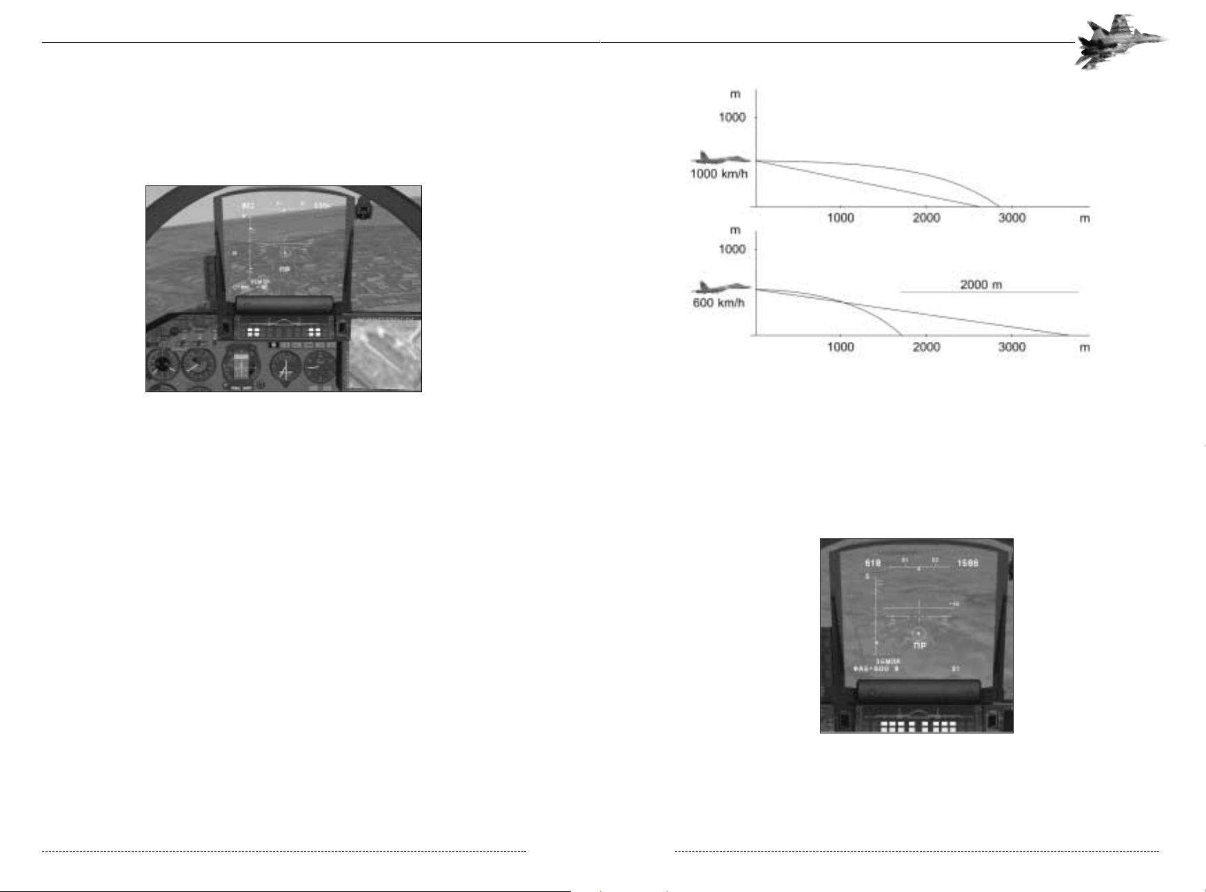
Effects of Release Speed on Bomb Range
Immediate Release
If the shoot cue is displayed, you can pull the trigger. This indicates that the position of the CCIP
pipper is within the bomb’s drop envelope. This releases the bombs immediately, and they will hit
the point designated by the Pipper.
Immediate Bomb Release HUD Symbology
CHAPTER 9: Air-To-Ground 167
By manoeuvreing the aircraft, place the aiming reticle directly over the target designator. If you are
within the weapon’s minimum and maximum launch ranges, the shoot cue appears. If you are outside of the weapon’s effective range, the reject cue appears. When using the cannon, it fires 25
rounds per salvo.
Firing Unguided Rockets
Note that you can fire both the cannon and rockets without radar locking a target. Simply place
the aiming reticle over the desired location and fire.
Dropping unguided bombs.
Unguided bombs are traditional weapons effective against enemy fortification and military plants,
railway junctions, and soft targets such as personnel and light armored vehicles. Typical bombing
altitudes range from 300 to 1500 meters with typical airspeeds from 500 to 1000 km/h. Note also
that unguided bombs are usually dropped in pairs to prevent not unbalancing the aircraft.
You can select the target either visually or by using the radar. While using these weapons, the
main task of the WCS is to calculate the Continuously Computed Impact Point (CCIP) and time
remaining to the bomb release and project this information on the HUD. Your task consists in
placing the CCIP Pipper on the target (or over the diamond-shaped Target Designator). Since the
course of an unguided bomb can be corrected to some degree (prior to release), the HUD displays minimum and maximum release ranges for unguided bombs. Manoeuvre the aircraft to place
the CCIP pipper over the target.
FLANKER 2.0
FLANKER 2.0
166 CHAPTER 9: Air-To-Ground
Page 86
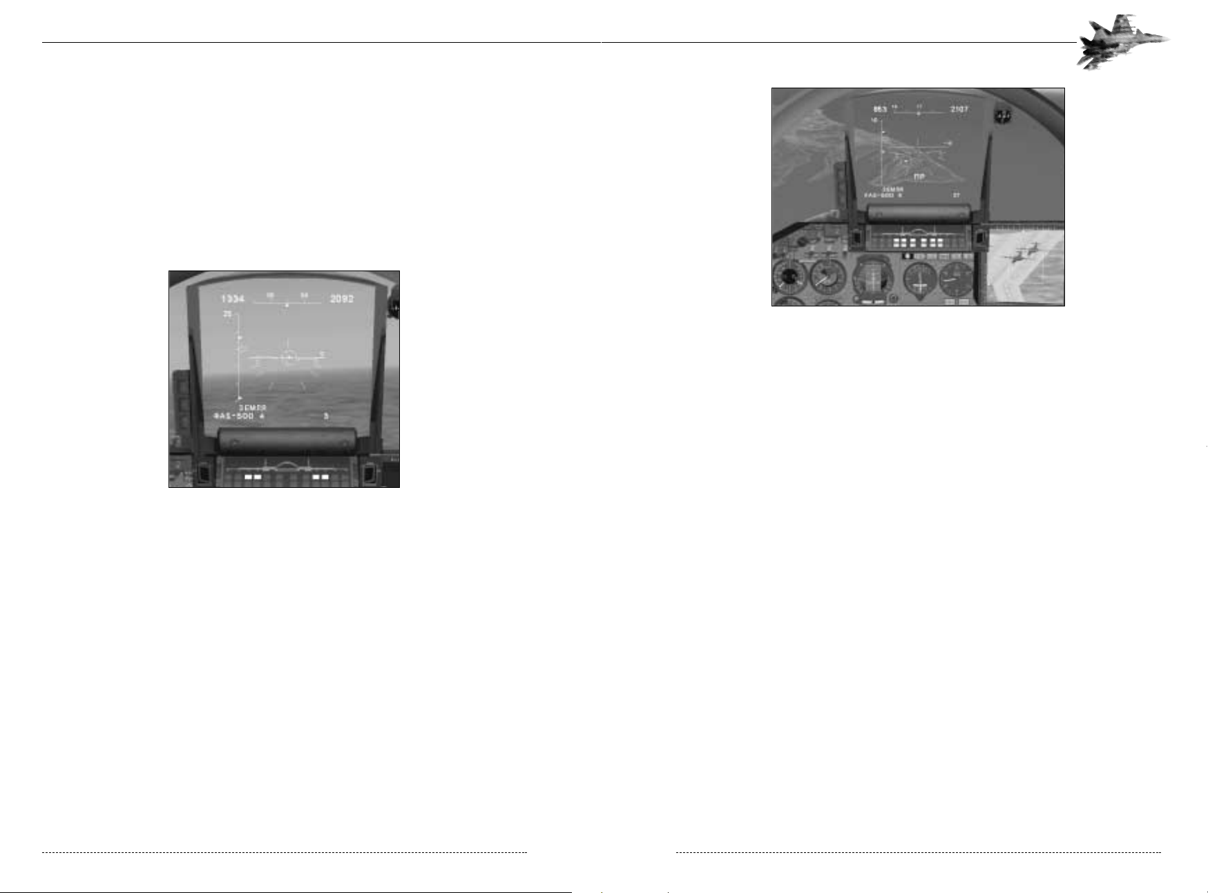
Guided Bomb HUD Symbology
Manoeuvre the aiming reticle to the center of the HUD and wait for the shoot cue to appear.
Holding the trigger prior to the shoot cue appearing ensures that the bomb will be released as
soon as the cue does appear.
CHAPTER 9: Air-To-Ground 169
Aeronautical Mode
If the location of the CCIP pipper is outside of the bomb’s flight envelope, the shoot cue will not
appear and you can not immediately release the weapon. In this case, pressing the trigger will
engage the Aeronautical Mode. letting the onboard computer decide when to drop the weapon.
The CCIP pipper is replaced by the aiming reticle. Keep the aiming reticle aligned in the center of
the HUD. When you pull the trigger, the onboard computer calculates the ideal release point and
displays a time-to-release counter in the lower right corner of the HUD. You may release the trigger now, but you must depress and hold the trigger as the countdown nears zero. If the trigger is
pressed when the countdown reaches zero, the computer will automatically release the bomb.
Aeronautical Mode HUD Symbology
If you wish to cancel the countdown, press Tab. If the trigger is not depressed when the counter
expires, the weapon system automatically switches out of Aeronautical Mode.
Dropping guided bombs
A guided bomb is a free-fall bomb equipped with some sort of guidance system (usually TV or
laser) that can make some corrections to the bomb’s flight path. When selected, the aiming reticle
appears in the HUD indicating where the bomb’s seeker is focused. Disable the radar and steer
the bomb’s onboard seeker using the scan zone controls. When you’ve placed the bomb’s
crosshairs (in the MFD) or the aiming reticle (in the HUD) over the target, lock onto it by pressing
Tab. After a few seconds, the Weapon Readiness Panel should indicate the bomb is ready.
FLANKER 2.0
FLANKER 2.0
168 CHAPTER 9: Air-To-Ground
Page 87
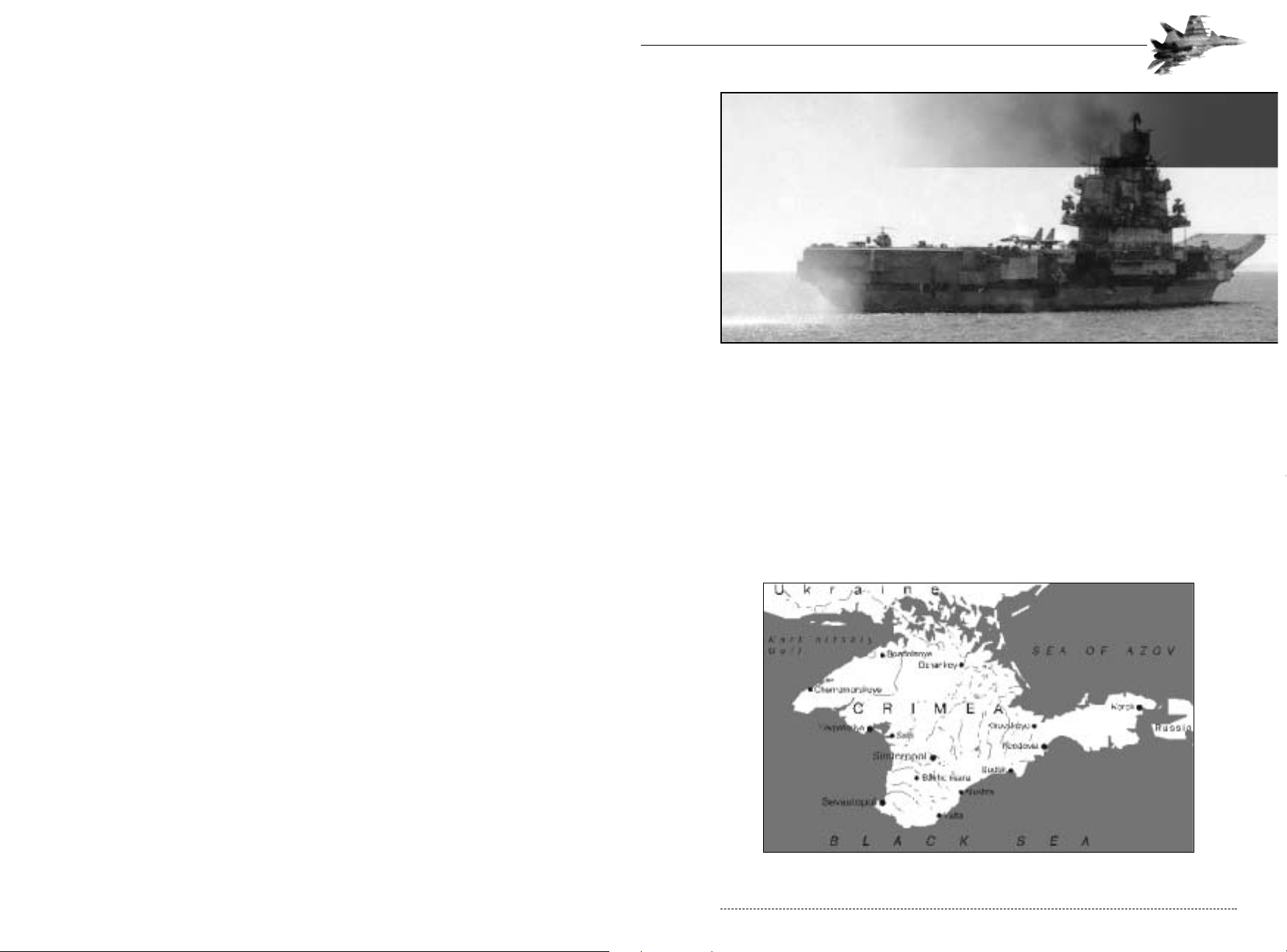
CHAPTER 10: Why Crimea 171
WHY CRIMEA?
The Flanker version you have bought introduces the Crimea as the theatre of play. For many centuries this small peninsula on the Black Sea has been a focus of interest, and its past and present
political situation are the main reasons why we have chosen it as the combat zone. The geography
of the Crimea is also well suited for flight simulation. Firstly, as a peninsula it has natural boundaries, secondly, the geographical characteristics of the Crimea - steppes, mountains, lakes, and
sea ensure diversity and ease of orientation.
Fortunately, war has not touched this picturesque territory too recently. All you will see in the
program and take part in is nothing more than fiction that, we hope, will never become reality.
But who knows.
10-14: Crimean Peninsula
CHAPTER 10
Crimea
CHAPTER 10
Crimea
Defense Visual Information Center - Department of Defense
Page 88

To solve the problem of the Black Sea Fleet, Russia carried out several rounds of negotiations with
the Ukraine from April 1992 to May 1993. Finally, on June 9, 1995 the two countries signed an
agreement, under which the Ukraine recognised Sevastopol as a naval base of the Russian Black
Sea Fleet. Furthermore, Russia received 81.7% and the Ukraine got 18.3% of the ships and vessels
of the Black Sea Fleet. However, the agreement did not decide the legal status and the conditions
of stay of the Russian Black Sea Fleet in the Crimea.
The process of negotiations between Russia and Ukraine is being further complicated by general
political tension in the peninsula. The Russians making up the majority of the Crimean population
are striving for independence from the Ukraine and for reunification with Russia. The population of
the Crimea has formed its own government actively opposing the politics of the Ukraine. The overwhelming majority of the population is striving to get Russian citizenship. Conflicts on inter-ethnical grounds have arisen between the Russians, Ukrainians, and Tatars forcing Kiev to bring in special units from the Ministry for Internal Affairs.
In March 1995 the Ukrainian Parliament abolished the institution of presidency and the
Constitution of the Crimean Republic that resulted in recurrent aggravation of the political situation
in this region.
CHAPTER 10: Why Crimea 173
Geography
In the north the Crimea is connected with the Kharkov Region by the Perekop isthmus. The Kerch
strait connecting the Black Sea and the Sea of Azov separates the Crimea from Russia. Sivash - a
series of shallow gulfs separated from the sea by a lowland sand spit - stretches along the whole
of the north-eastern coast.
The northern part of the peninsula is a plain covered by steppe; the southern part is occupied by
the Crimea Mountains that stretch from Sevastopol to Feodosia and consist of three parallel ridges
with gentle northern and steep southern slopes. The highest point of the Crimea is the RomanKosh mountain (1545 metres) situated to the north-east of Yalta.
The Crimea is blessed with a Mediterranean climate. The rivers of the Crimea are shallow. It also
has some large salt estuary lakes. The upper part of the peninsula has a system of canals.
The capital of the Crimea is Simferopol which has a population of 350,000. The main towns of the
peninsula are Sevastopol, Kerch, Dzhankoy, Yalta, Yevpatoriya, and Feodosiya. The Crimea is the
favourite recreation place of Russian and Ukraine leaders and heads of state. In 1991 during the
coup initiated by the supporters of the communist regime Michael Gorbachev, the president of the
late USSR, was blockaded at his dacha in Foros in the south extremity of the Crimea.
Historical background
The most ancient artefacts found in the Crimea date from the Palaeolithic period. A Scythian State
arose in the steppe part of the Crimea in the third century BC. All subsequent history of the
Crimea is a history of wars.
In the 3-4th centuries A.D. Goths and Huns seized the Crimea and founded the Tmutarakhan
Principality. In the thirteenth century A.D. Mongol-Tatars invaded the peninsula and founded the
Crimean Ulus of the Golden Horde. After the Golden Horde had collapsed in 1443, the Crimea
Khanate arose and remained in existence for about 300 years as a vassal of Turkey. During all those
centuries the Russians and Ukrainians fought side by side against the Tatar and Turkish raids.
As a result of the long war between Russia and Turkey the Crimea was made a part of Russia in
1783. During the “Crimean War” that lasted from 1853 to 1856 Russia waged war with Turkey,
England and France and was badly defeated. But the peninsula remained in Russian hands.
The territory of the Crimea was also an arena of military operations during the Civil War in Russia
(1918) and WW II (1941-1945). The Crimean Conference of the heads of 3 allied states - victors
in WW II took place in Yalta in 1945. Josef Stalin represented Russia; Franklin Roosevelt represented the USA; and Winston Churchill represented Great Britain.
In 1954 Khruschev transferred the Crimean Region as a gift from Russia to the Ukraine. When the
USSR collapsed and the Commonwealth of Independent States (CIS) was formed in 1991, the
Crimea remained technically part of the Ukraine.
At present, the most acute problem that may result in an escalation from a political conflict to a
military one is the problem of the Black Sea Fleet. The main reason of disagreement is the fact that
after the collapse of the USSR both the Ukraine and Russia made claims to the Black Sea Fleet
although historically the Fleet was always Russian. Furthermore, the main naval base of the Black
Sea Fleet is Sevastopol and many other military installations of the late USSR on which Russia is
making claims have turned out to be on the Ukrainian territory.
FLANKER 2.0
FLANKER 2.0
172 CHAPTER 10: Why Crimea
Page 89
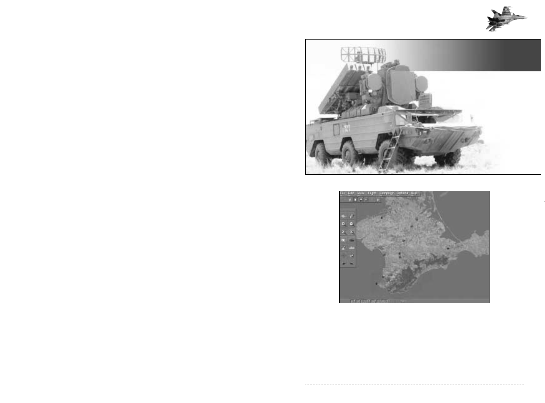
CHAPTER 11: Introduction to the Mission Editor 175
11-1: The Mission Editor Screen
INTRODUCTION TO THE MISSION EDITOR
The mission editor is the heart and soul of Flanker 2.0. This is where almost everything happens.
You can build mission and campaigns here. You can start multi-player games here. You can edit
mission and track files.
The different menus will be discussed first and then instructions on how to build missions and
campaigns will be displayed later in this chapter.
CHAPTER 11
Introduction to the Mission Editor
CHAPTER 11
Introduction to the Mission Editor
Defense Visual Information Center - Department of Defense
Page 90

Options Failures Specify failures that may happen to your aircraft
for training purposes
Skills Set skill levels for all automatic objects;
specify your aircraft’s survivability
Met Report Specify meteorological conditions (wind, temperature,
cloudiness, etc.) for the active mission
Colours Change the colour of the icons in the Editor and
the AWACS view.
Help About Su-27 Flanker Show the program info, version number
and copyright notice
Standard Toolbar
11-2: The Standard Toolbar
Beneath the Menu Bar is the Standard Toolbar, which contains a set of standard buttons, typical
to many windows applications.
11-3: The Planning Toolbar
CHAPTER 11:Menus 177
MENUS
MENU MENU ITEM HOT KEY MEANING
File New Mission Ctrl+N Create a new mission
Open Mission Ctrl+O Open an existing mission
Save Ctrl+A Save the active mission to disk
Save As Save the mission under another name
Exit Alt+X Quit the program
Edit Undo Ctrl+Z Undo the last editing change
Redo Ctrl+Y Re-install the last edit cleared with the Undo command.
Delete DEL Delete the current selection on the map
Classify Mission Assign the active mission to a class and protect it
with a password
Declassify Mission Declassify the active mission to have access to all
mission resources; password will be required
View Hide Objects Ctrl+H Hide or show specific objects on the map
Crimean View Ctrl+1 Return the map to the default magnification level
around the Crimean peninsula.
Zoom In Magnify the map by a factor of 2 or in the dragged box
Zoom Out Scale the map down by a factor of 2
Object View When a unit is selected, this will take the view down
to a very close level.
Region View Magnify the map to a regional view, centered on the
selected object.
Flight Briefing Ctrl+B View/edit the mission briefing
Debriefing Ctrl+D View a debriefing when a saved misson is the loaded.
Choose Phase Choose the phase in a loaded campaign.
Start Mission Ctrl+F Start the current mission
Network Play Ctrl+L Begin a network multi-player session.
Chat Ctrl+M Chat with other players during a multi-player session.
Record Track Ctrl+R Start the mission and record a video sequence
Play Track Playback the last recorded video sequence
Video Edit Ctrl+V Start the video sequence and enable its editing
Campaign Phases Create and edit the phases within a campaign
Mission Conditions Set the mission conditions within a phase
Contingency Planning Review all of the units in campaign.
Remove Objects Alt+Z Remove an object from a condition set in a phase.
FLANKER 2.0
FLANKER 2.0
176 CHAPTER 11: Menus
Start Mission
New Mission
Open
Save Delete
Delete
View Object
Zoom Out
Forward View
New SAM
New Ship
New Static Object
Redo
Crimean View
Zoom In
Backward View
New Aircraft
New Radar
Primary Target
Undo
Page 91

Panning
If you are interested in a particular area, which is beyond what’s on screen you can shift the map
in the desired direction. You can do this by simply holding down your left mouse button (which
will change to the Pan state) when the cursor is in the Select or Edit state and move the map in
the desired direction.
Zooming
If you are interested in details of a given area on the map or want to have a look at the entire theatre of play, change the map scale by zooming in or out.
To zoom in
1. Click on the Zoom In button on the Planning Toolbar or select Zoom from the mouse right
click menu
2. Do one of the following:
• To scale the map up by a factor of two, click the left mouse button in the center of the map
area you want to enlarge.
• To enlarge a given area to the size of the map window, select a rectangular region on the map
by pressing the left mouse button to anchor one corner of the area and then dragging the
mouse pointer. The stretching Rubber Rectangle shows the region being selected. Release the
mouse button to complete zooming.
Note that Zoom In mode remains active until disabled, so you can apply zooming in repeatedly. To
disable, “unpress” the Zoom In button, click on it with the mouse or click the right mouse button
anywhere on the map.
To zoom out by a factor of 2
• Click on the Zoom Out button.
To view the Crimean theatre of play
• Click on the Crimean View button or press Ctrl+1.
To restore the previous map scale
• Click the Backward View button.
You can apply this command repeatedly to restore any map scale applied in the current session.
CHAPTER 11: Working With the Map 179
Planning Toolbar
The Planning Toolbar down the left-hand side contains buttons for scaling the map, placing aircraft, ships, SAMs, radars, and other objects.
The buttons provide you with quick pictorial access to the Mission Editor commands, many of
which are duplicated in the menus. Note that you can move the toolbars to wherever you see fit.
11-4: Status Bar
Status Bar
Along the bottom of the program window runs the Status Bar, which shows information on the
Mission Editor mode, the current geographical coordinates of the mouse pointer, and a short help
line on the selected Toolbar button or menu command.
WORKING WITH THE MAP
When working in the Mission Editor, you will be required to intensively use the map for identifying
targets, planning routes and placing objects. While using the map, you can:
• scroll the map in any direction
• zoom the map on the screen in or out
• grid coordinate.
Cursor States
You mouse cursor changes states depending upon the mode it is in. The following are some of
the cursor states:
11-5: Cursor States
FLANKER 2.0
FLANKER 2.0
178 CHAPTER 11: Working With the Map
Mouse Pointer Coordinates
Select
Pan Map
Edit
Zoom In
Place Aircraft
Target Selection
Place Static Object
Place EWR
Place Ship
Place SAM
Current Mission
Page 92

tracking radar of a SAM system
search radar of a SAM system
SAM launcher
AAA or SAM system housing both radar and launcher/guns
portable SAM launcher (Igla)
static object
primary target
11-6: Editor symbols
When working with objects on the map you can:
• Select a single object or a group of objects;
• Move or delete a group of objects;
• Hide or show objects;
• Undo editing changes.
Note, however, that the Mission Editor is not a graphical editor as it may seem to be. That is
why some features typical to a graphical editor may be different in the Mission Editor or not implemented at all.
Selecting objects
To select objects on the map, you should first make sure that none of the special map modes
(zooming)
and the modes for placing new objects are active. This will be witnessed by the absence of
sunken button on the Planning Toolbar and the cursor state.
To select an individual object, click it with the left mouse button. The selected object will be highlighted by the selection colour (by default, yellow), and the corresponding dialog box describing
the object’s properties (for example, a country to which it belongs, object type, orientation, skill
level, and so on) will appear on screen.
To select an aircraft and its route, click on any of its waypoints. In so doing, all the waypoints
enlarge and display their ordinal number on the route (from 0 to 15). Furthermore, the current
waypoint and the legs of the selected route turn to yellow.
CHAPTER 11: Working With Objects 181
WORKING WITH OBJECTS
When planning existing missions or building new ones, you will be placing aircraft, ships, SAM
systems, possibly static objects and designing aircraft routes. In our terminology, all the above are
objects. Some of them are active objects (ships, aircraft, radars, SAM systems), whereas other
objects are static (automobiles, tanks, fuel trucks...). Active objects have particular levels of artificial intelligence and behavior; they are marked by an individual symbol irrespective of the current
map scale. You can place static objects in an arbitrary or specific way. For example, increasing the
number of aircraft parked on an airfield makes it a more interesting ground target.
A special case is a SAM system, which consist of several units operating as a functional entity. For
example, a standard S-300PMU Grumble system consists of one surveillance radar, one engagement radar and up to 6 launchers, each of them on a separate chassis. In similar cases all units
comprising a system are marked by individual symbols on the map.
The table below contains a list of all symbols used on the map.
airfield
take-off waypoint
landing waypoint
Ground Alert Intercept station. This is the only waypoint of the GAI sortie
turning point of an unselected route. Such a waypoint is always displayed
in the colour of the country owning the aircraft
turning point of the selected route. The number indicates the waypoint’s
ordinal number (from 0 to 15).
action point of an unselected route. An action point implies a particular
action associated with this waypoint (rocket attack point, start of
a CAP station)
action point of the selected route. The number indicates the waypoint
order number.
ship
Early Warning Radar station
FLANKER 2.0
FLANKER 2.0
180 CHAPTER 11: Working With Objects
Page 93

Previewing objects
If you want to have a look at a 3D model of a particular object and to get a description of its main
specifications, select the object in the Encyclopedia from the Main menu.
Undoing changes
If you need to undo the last action such as selecting, moving or deleting a single object or a group
of objects as well as changing object properties, click on the Undo button on the Planning Toolbar
or select Edit, Undo from the menu (press Ctrl+Z). You can undo as many changes to objects as
you need because the Mission Editor stores records about all changes made in the current session.
CHAPTER 11: Working With Objects 183
After selecting a unit you can invoke a shortcut menu, by pressing the
right mouse button. This menu which lists operations available for the
object. A typical shortcut menu is shown below.
While planning a mission, you might want to move a group of objects the
same distance or delete them. To include an object into a group, click it
while holding down the Control key.
If you need to unselect an individual object, click the left mouse button
anywhere on the map off objects or select another object. To exclude an
object from a group, select it again with the Control key held down.
Moving and deleting objects
To move a single object or a group of selected objects, place the mouse pointer on this object or
any object in the group, hold down the left mouse button and drag the object or the entire group
to the new place on the map. Then release the button.
To delete a selected object/group of objects, click the Delete button on the Standard Toolbar, or
press the Delete key. When you delete waypoints (using the Delete button in the Airgroup
Planning menu), the remaining waypoints of the route will be automatically renumbered.
Hiding objects
If you think that the map shows too many symbols of
objects, making it difficult to plan a mission or understand
a combat situation, you can temporarily hide those symbols which are of no interest to you at that moment. You
can do this with an individually selected object or a group
of objects or you can use a specially formulated criterion,
for example, hide all enemy ships.
To hide an individual object or a group of selected objects
choose Hide from the shortcut menu or. The symbols of
the selected objects will disappear from the map together
with the objects they label. Note, that if you try to hide any
waypoint of a route, this leads to hiding the entire route.
Activate the Hide Object dialog box from the View menu
or by pressing Ctrl+H. Hide objects by unchecking the
object type, and show them by checking.
Use the Side field for selecting the side whose objects you
want to hide or show, for example, Russia or Ukraine. You
can also click the Show All button or Hide All button.
Note. You can hide or show air defense areas and SAM threat zones, which are displayed on the
map. An air defense area covers the maximum detection range of the Early Warning Radar or
SAM radar. Note that the radar itself may be hidden.
If you want to hide a specific ship, aircraft, or other active object, point to the object and click the
right button. This will activate the shortcut menu; select Hide.
FLANKER 2.0
FLANKER 2.0
182 CHAPTER 11: Working With Objects
Page 94

CHAPTER 12: Planning Your Mission 185
PLANNING YOUR MISSION
Missions
If you want to create a mission from beginning to end fully using the resources of all sides taking
part in the hostilities, you will find all necessary information in Chapter 13, “Building new missions”.
However, we suggest that you familiarise yourself with the information in the given chapter before
tackling such a serious task, as this very chapter describes the main methods of planning.
Normally, the process of mission planning and execution includes the following steps:
1. Loading a mission of a certain class into the Mission Editor.
2. Familiarisation with the mission objectives.
3. Depending on the class of mission and resources available: planning combat tasks for all the
objects that should take part in the mission (aircraft, EWR stations, SAM systems, and ships).
4. Flying the mission on your own or performing in automatic mode.
5. Debriefing and mission analysis.
12-1: Select Mission menu
CHAPTER 12
Planning Your Mission
CHAPTER 12
Planning Your Mission
Defense Visual Information Center - Department of Defense
Page 95

Description
This text box contains the detailed information about the mission objectives, enemy forces,
available resources, and weather.
No matter who you are - a novice pilot or a general, you will be given the mission objectives
You should take good account of the meteorological conditions.
Once you have understood the information in the briefing, turn your attention to the map. The map
will show you the targets you must attack or defend. By convention, the targets to be attacked
(SAM sites, ships, buildings, ground vehicles, and so on) will be marked by red flags and/or
numbered triangles.
TRACKS (DEMO MISSIONS)
If you wish to record a mission, then select Flight, Record Track (Ctrl+R) instead of Start Mission.
At the end of the mission, you will be prompted to save the track. If you do, then it will be loaded
in the editor. You can view the object information within the editor, but you cannot change it
(since it is a recording). If you want to add voice to the recording, then, using a microphone,
select Video edit from the Flight menu and hold down the 0 (zero) key while speaking into the
microphone. You can talk as long as you want and in as many segments as you want.
Play Track
If you have a track file loaded in the editor and want to watch it, then select Flight, Play Track. If
you select Start Mission, you will be flying the mission and not watching it. When watching the
track you can use any camera view. The camera views that you used in the original recording will
also be recorded. At anytime during the playing of a track, you can take over the aircraft yourself
(assuming it is an aircraft assigned to “Me”) by selecting the Esc key. You will then be flying a
mission where you interrupted the track.
Video Edit
If you wish to change the camera views that take place in a track, select Flight, Video Edit
(Ctrl+V). This will start the track and record any new camera view selections you make.
UNDERSTANDING COMBAT TASKS
Each active ground, naval, or airborne object taking part in the mission has a specific task that it
carries out according to a particular degree of “artificial intelligence”. Besides, there are static
ground objects (tanks, automobiles, etc.) which in the current version of the sim cannot move
and are not provided with their own logic. However, they serve as potential targets for attacking
or defending.
The main distinction of an aircraft from other active objects lies in the fact that you can (and must)
plan for it a certain combat task according to which the aircraft will act. (You should create the
flight plan, choose the weapons and fuel load, allocate the targets). As for ground and naval
objects, you can only specify their locations. Nonetheless, our simulator will allow you to specify
the skill level for both the pilots or crews of aircraft and the crews of SAM systems, ships or the
CHAPTER 12: Understanding Combat Tasks 187
Loading and Saving Missions
To load a combat mission, select File, Open Mission. First, select the All Flanker Missions class in
the List files of type field, for example. This will display a list of all missions of that class which
reside in the current directory. Select the desired mission from the list. The Title field may change
to show the brief message related to the selected mission. In so doing, the text box below shows
the mission briefing.
After you have found the desired mission, load it into the Mission Editor by pressing the OK button. If you are already familiar with the mission and don’t need to view the map, you can start it
immediately by pressing the Run button.
Note that if you try to load a mission while editing another one, the Mission Editor will prompt you
to save the active mission.
As soon as you finish planning the mission, you should save it. Otherwise, when you start the mission the simulator will run the old version of the mission. To save the active mission, select File,
Save or press the Ctrl+A keys. The mission will be saved under the same name as when it was
loaded into the Mission Editor. Sometimes it may be inconvenient because this erases the initial
version of the mission to which you might want to return later. To save the mission under another
name, select File, Save as. This activates a dialog box where you have to specify a new file name
for the active mission. The file extension can be omitted since the Mission Editor automatically
adds ‘.mis’ to the file name. To label the mission with a brief message, type the required text in the
Title field. To complete the saving, press OK.
Mission Briefings
When loading an unfamiliar mission, you first
should get the description of the mission
objectives and operational intelligence.
Additionally, this information includes loadout
information, a weather report, and mission
start time.
To get a mission briefing, select Flight, Briefing.
The start time for the entire mission is selected
by filling in the “Start at” area. If you select a
different time in the “till” area, then the mission
will start at a random starting time, somewhere
in between the 2 times.
You may also change the country that the player will be fighting for in the “My Country” box.
You can write a briefing that the player will see
when they select the mission in the Description
area. You need to select the OK key in order
for all of your changes to take effect.
FLANKER 2.0
FLANKER 2.0
186 CHAPTER 12: Planning Your Mission
12-2: Briefing menu
Page 96

Fighter sweep
The fighter sweep mission is a combat task that involves combing air space to attack enemy fighters or other types of aircraft. The main objective of a fighter sweep is winning air superiority and to
ensure unimpeded use of the air space by allied aircraft.
In a fighter sweep you can use the Su-27, MiG-29 and MiG-23 fighters. All the aircraft taking part
in this task carry long-range and short-range AAMs and the Su-27 in addition to them may carry
an external active ECM station Sorbtsiya.
Since the aircraft taking part in a fighter sweep may find themselves at a considerable distance
from their airfields and take part in prolonged dogfights, their fuel load will be a crucial factor.
Certain aircraft such as the MiG-23 and MiG-27 can carry additional external fuel tanks.
Combat Air Patrol (CAP)
For the purposes of defending a relatively small area you can use the Combat Air Patrol (CAP) or
Ground Alert Intercept (GAI). In a specific situation the choice of a CAP or GAI mission depends
on many factors. Among them are the nature of a probable enemy attack, reliability of the information about its route, the number of defending fighters and their capabilities.
The CAP mission implies flying a large rectangular pattern round and round following a given route
to defend some area from enemy aircraft. This type of task does not involve spotting and destroying enemy ground targets or a significant deviation from the planned route to intercept aircraft.
One of the advantages of the CAP is the possibility of intercepting enemy aircraft at long distances
from the target being defended. This is especially important if you expect enemy aircraft armed
with long-range stand-off weapons (for example, cruise missiles) that can be launched many miles
away from their targets. Besides the time factor, the CAP is well suited to situations where the
direction of approach or route of enemy aircraft is known with some degree of certainty.
A typical CAP route degenerates into a heavily flattened ellipse, the long axis of which is lined up
in the direction of possible threat (see the figure below). You can set up a CAP station for
patrolling with the use of both one and several aircraft. (For example, it can involve two aircraft flying toward one another.)
The distance at which you place a CAP station depends on many factors: the number of patrolling
aircraft, the size of the area being defended, and the nature of its ground based air defense.
Sometimes the use of GAI or only ground based air defense may be more efficient. But beware of
standoff weapons!
When planning a CAP mission, the choice of altitude and speed of flight is of no small importance.
Plan to patrol at the expected altitude of the incoming enemy aircraft and take your weapons load
and weather into account. Be aware that high altitude CAP will make life for low level interdiction
real easy and a high/low CAP sandwich might be more suitable.
The crucial factor while patrolling will be the fuel load limiting the distance and duration of CAP. All
automatic aircraft in our simulation stop patrolling and return to base in a straight route as soon as
their fuel falls to the guaranteed minimum required for the return flight.
On the whole, the use of CAP alone for air defense is difficult and insufficient. However, sometimes CAP may be fairly well suited, especially in the following circumstances: the area being
defended is not very large; your fighters have sufficient resources; the sector of possible threat is
limited; and if the enemy attacks in small force without large fighter escort.
CHAPTER 12: Understanding Combat Tasks 189
personnel of EWR stations. One or another skill level specified for an object will dictate its tactics.
Our program allows you to specify for each active object one of the following skill levels: Average,
Good, High, Excellent. On the whole, the higher the skill level the less the reaction time of the
object, the less the time the object spends on reaching a decision and the better the precision of
trajectories and targeting..
Computer-controlled (automatic) aircraft should know how to accomplish their combat tasks
because aircraft of the same type can act differently even within the limits of the same mission. For
example, the first MiG-29 may effect an intercept, the second - fly a simple CAP mission, whereas
the third MiG-29 may seek and destroy enemy radar. Apart from the fact that the type of combat
task determines the tactics of the aircraft, it also affects weapons selection. In particular, this
means that if the aircraft gets a CAP task you won’t be able to load bombs onto it.
To carry out the combat task allocated to your aircraft, you have to do it yourself. By this is meant
that if you have chosen (or you have been allocated) a bomb strike, then you have to fly the aircraft to the bomb delivery point and deliver the bombs on your own, though you can get some
help from the autopilot. Furthermore, the type of combat task allocated to you and the real results
of its execution are taken into account during evaluation of the success of your mission.
Note that the choice of a combat task only decides the general behavior of the aircraft and the
available options of weapons. The following are descriptions of combat tasks that can be assigned
to aircraft. Naturally, you can allocate only certain combat tasks to a specific type of aircraft. It would
be strange if you could assign an intercept task to the Su-25 or a bombing task to AWACS aircraft.
Observation
By default, each new aircraft added to a mission is devoid of any specific task. Correspondingly, it
will not have any weapons loaded except perhaps the cannon. Such a plane does not take part in
any active actions against enemy aircraft or ground installations and just follows its route. Under
the threat of an enemy attack the aircraft will try to evade it.
Intercept
This is a defensive tactic whereby the aircraft must carry out an active search of incoming enemy
aircraft and/or receive targeting data from ground based or airborne radar. This type of combat
task is reserved for large scale defense and active patrolling and you should not use it while
defending a small area or a local installation. The interceptor while chasing the enemy may deviate
far from his planned route and the area he is supposed to defend will be left undefended.
This task supposes the use of both long-range and short-range AAMs (R-27 Alamo, R-73 Archer)
for intercepting enemy aircraft and cruise missiles and the use of R-77 Adder missiles for intercepting enemy guided missiles. The most suitable aircraft for intercepts are the Su-27 and the
MiG-31. Among western fighters this task would be typically carried out by the McDonnel
Douglas F-15, which carries four medium-range AIM-120 AMRAAM missiles and four shortrange AIM-9P Sidewinder missiles.
FLANKER 2.0
FLANKER 2.0
188 CHAPTER 12: Understanding Combat Tasks
Page 97

Ground attack
This task consists in purposely searching for enemy ground targets (plants, railroad stations, airfields) in a given area then attacking and destroying them in general using bombs. This type of
mission usually involves using unguided bombs weighing from 250 to 1500 kg or the KMGU unified containers. In addition, the aircraft can destroy targets with the aid of unguided rockets.
Close Air Support (CAS)
CAS involves actively searching for enemy ground targets on the battlefield and destroying them.
Here absolute precision in delivering strikes is not of crucial importance. This type of mission usually involves using the S-8, S-13, S-24, and S-25 unguided rockets and unguided bombs. The
Su-25 ground attack aircraft is best suited to CAS, though such planes as the Su-27, MiG-29 or
and MiG-27 can successfully handle this task.
AWACS (Airborne Warning And Control System)
This task can only be allocated to the A-50 AWACS aircraft, which is a highly modified version of
the IL-76 transport aircraft or to the American E-3A. The AWACS aircraft flies according to a
planned straight or circular route and alerts allied aircraft, SAM sites, and ships when it detects
enemy aircraft.
The advantages provided by the AWACS aircraft are evident. Furthermore, the S-300PMU and
Buk SAM systems can receive targeting data directly from the AWACS even when their own
acquisition radar have been destroyed. The sole drawback of the AWACS aircraft is its high vulnerability, especially as it is a much prized target for enemy fighters. Often you can use ground
EWR stations instead of the AWACS aircraft to assist you.
Mission Classes
All mission classes differ from one another by the number and type of resources you will have at
your disposal and, hence, by the amount of work involved. The Flanker offers you three combat
mission classes:
• Pilot mission
• Squadron leader mission
• General mission
In our simulation you can plan and perform several versions of the same mission to compare the
results and find the optimal solution.
Potential detection zones and threat zones related to enemy AAA, SAM systems and ships are
shown on the map as as circles, however, the objects themselves may be concealed. Naturally,
you should plan missions allowing for these threat zones. However, note that such a zone represents the maximum engagement envelope of the corresponding enemy weapon and does not
consider terrain masking or aircraft’s altitude and speed. This means that carefully planned routes
allow aircraft to successfully fly even in threat zones.
CHAPTER 12: Understanding Combat Tasks 191
Ground Alert Intercept
In many circumstances GAI usually proves to be preferable and more flexible for the organization
of air defense than CAP. When taking part in a GAI mission, the aircraft is on alert duty on the runway with warmed-up engines. On receiving AWACS targeting data the aircraft takes off and
effects an assisted intercept. Since high top speed and climb rate are extremely important for GAI,
the most optimal aircraft for this task are the Su-27, MiG-29 and MiG-31. Note, however, that in
our program the GAI task can be allocated only to automatic aircraft. We wouldn’t want you to
stay Earth bound sitting on hot alert in the cockpit for long stretches of time waiting for intercept
data. This can prove to be very boring and frustrating. If the enemy attacks with several aircraft,
the aircraft on GAI duty will take-off one after another intercepting one enemy aircraft each.
(Provided that you have allocated the GAI task to a sufficient number of aircraft.)
When planning this type of mission you don’t need to design waypoints and action points. All you
have to do is just set the takeoff point, declare it as a GAI station, and let the EWR and AWACS
systems vector the aircraft accordingly. Note that intercept aircraft rarely have a complete weapons
suite in order to offer maximum rate of climb and manoeuvreability. Note that when planning GAI
the aircraft on hot alert don’t appear on the runway until the target data becomes available.
The GAI concept is not without drawbacks. First of all, the EWR systems must detect enemy aircraft in good time; otherwise the aircraft on GAI duty on the airfield may become sitting ducks .
Furthermore, to repulse attacks from any direction, the airfield with the aircraft on GAI duty must
be sufficiently close to the installations being defended.
Escort
This task is allocated to fighters and involves escorting allied aircraft (transport aircraft, bombers,
or attack aircraft) and defending them in some air corridor along the route from possible attacks of
enemy aircraft. In doing so the escorting fighters should not engage in fights with the enemy aircraft if the latter do not close in on them and do not display aggressiveness.
You should plan the number of escorting fighters depending on the importance of the combat
task allocated to the escort and the probability of an encounter with enemy interceptors on route.
Antiradar
This task involves searching for enemy EWR stations and SAM sites in a given area, and attacking
and destroying them using antiradar missiles of the Kh-25MP Karen or Kh31P Kegler types. Note
that you cannot use antiradar ASMs against airborne targets (for example, AWACS aircraft), as
antiradar missiles are not designed to track fast moving manoeuvreing targets.
Antiship strike
This task consists in actively searching for enemy surface ships in a given area then attacking and
destroying them. In so doing you can use antiship missiles of the Kh-15 Kickback, Kh-31A Kegler,
Kh-35 Krypton types or cruise missiles of the Kh-55 Kent and Kh-65 types.
Pinpoint strike
The Pinpoint strike mission involves active search for ground and surface targets in a given area and
attacking and destroying them using precision missiles of the Kh-25 Karen, Kh-29 Kedge types, or
cruise missiles of the Kh-55 Kent and Kh-59 Kingbolt types. Besides the above weapons, to deliver
a pinpoint strike, the aircraft can carry guided bombs of the KAB-500 or KAB-1500 types.
FLANKER 2.0
FLANKER 2.0
190 CHAPTER 12: Understanding Combat Tasks
Page 98

COMBINED ARMS ARMY TANK ARMY
Tank Divisions 1 to 2 2 to 4
Motorized Rifle Divisions 2 to 4 1 to 2
Artillery yes yes
Missile Support yes yes
Air Defense yes yes
Intelligence yes yes
Logistics Assets yes yes
Three to five armies comprise a front, the largest wartime field formation. Fronts are deployed
throughout the theater of action along strategic axes leading to key enemy positions.
Russian offensive operations utilize an echelon, or wave concept. The first echelon, consisting of
roughly 1/3 to 1/2 of the entire formation, attacks first, penetrating as deep as possible through
the enemy lines. The second echelon held in reserve, launching a second wave through ground
gained by the first attack. The two echelon’s continue to “leap frog” toward the enemy’s rear.
Russian ground forces would consist mainly of T-80 and T-72 Main Battle Tanks along with BMP1, BMP-2, and BMD infantry fighting vehicles. BTR-50, BTR-60, BTR-70, and BTR-80 Armored
Personnel Vehicles would be quite prevalent. SA-4 and SA-11 SAM systems will deploy at the
Army/Front level. SA-6, SA-8, and SA-15 will deploy at the Division level. SA-9 and SA-13 will
deploy at the Regiment level. Man-portable SAMs (SA-7, SA-14, SA-16, SA-18) will accompany
all ground forces. Su-27, Su-33, MiG-29, and MiG-31 aircraft will provide the backbone of Russian
aviation, with MiG-23, MiG-27, and Su-25 aircraft performing a wide variety of tasks. The Black
Sea Fleet, including 4 cruisers, 5 destroyers, and 21 frigates, has largely been under Russian control, despite various “joint control” agreements between Russia and Ukraine.
Ukraine
Once part of the Soviet Union, Ukranian military forces are dominated by Soviet-built equipment
and tactics. Ukranian army, numbering some 212,000 troops, is divided into five major commands.
Main Battle Tanks: 345 T-80; 1,320 T-72; 2,345 T-64; 85 T-62; and 680 T-54/55
AIFV: 1,325 BMP-1; 1,460 BMP-2; 6 BMP-3; 124 BMD; 490 BRM
APC: 220 BTR-60; 2,000 BTR-70; 450 BTR-80; 40 BTR-D
Artillery: 3,685
SSM: 132 Scud; 140 FROG/SS-21
SAMs: SA-2; SA-3; SA-4; SA-5; SA-6; SA-8; SA-10; SA-11; SA-12A; SA-1
Naval Bases: Sevastopol, Odessa
Navy: 2 Krivak-III; 1 Petya-II,1 Grisha V
Naval Aviation: 63 MiG-29; 45 Su-17; 44 Su-25; 18 Tu-16; 39 Tu-22M.
Air Force: 140 MiG-23; 73 MiG-25; 146 MiG-29; 57 Su-15; 66 Su-27; 34 Su-25; 166 Su-24
CHAPTER 12: Understanding Combat Tasks 193
Pilot mission
Here the combat task is usually formulated very particularly, for example, strike a particular ground
target or intercept an enemy fighter. We recommend that you begin mastering the Mission Editor
from the Pilot mission class as it is the simplest.
The pre-set flightplan, weapons and fuel load of your aircraft are typical for a Pilot mission. As a
pilot, all you can do in the Mission Editor is familiarise yourself with the flightplan on the map. You
neither can change your flightplan, weapons load and fuel load, nor add new objects to the battlefield. All you should do is fly your mission strictly following the pre-set flightplan. The main criteria
that the program will use for evaluating the success of your sortie are the achievement of the mission objectives, total flying time, the number of destroyed enemy aircraft, and the type and quantity
of the weapons employed.
Note, that while being just a pilot you generally cannot influence the outcome of the entire mission
where other allied aircraft, ships, and SAM systems can also take part. However, in our sim the
success of any pilot mission is evaluated only by your own combat actions. The detailed debriefing
of your sortie showing all the events that occurred during the mission will be made in the
Debriefing dialog box.
Squadron leader mission
The Squadron leader mission class gives you more leeway in deciding how to achieve the mission
objectives than a junior pilot. A squadron leader can select the number of aircraft he will need (up
to four), the skill of his wingmen, and the aircraft ordnance. He can modify or design the flightplan
for his wing and designates action points.
A squadron leader cannot add new objects to the mission or change properties of the existing
ones. His goal is to achieve the mission objectives with the least losses. The success of a
squadron leader mission is determined only by the actions of the squadron irrespective of how
lucky the other allied forces were.
General mission
Combat missions of the General mission class are the most difficult for planning. They require fine
tactical thinking. For example, he can be ordered to defend a city from enemy aircraft raids, or to
deliver a mass airstrike on enemy installations.
To achieve the mission objectives as a general, you have at your disposal considerable resources
including a range of aircraft, SAM systems, radar, all types of aircraft ordnance, and unlimited fuel
supplies. Note that in any general mission you can remain as an observer or take part in the mission
as a pilot or squadron leader. In distinction to pilot and squadron leader missions, the program evaluates the success of a general mission primarily by the actions of all the allied air, naval, and ground
forces. To a lesser extent the mission result will depend on your actions as a pilot, though it may
happen that you will be the very person who will predetermine the outcome of the entire mission.
Nation Briefing
Russia
Despite its economic woes, Russia still fields the largest military force in the area included in
Flanker. Soviet military doctrine, which undoubtedly forms the backbone of current Russian military
philosophy, is based on the divisional concept. Tank, Motorized Rifle, and Airborne divisions are
combined into armies. Typical armies consist of:
FLANKER 2.0
FLANKER 2.0
192 CHAPTER 12: Understanding Combat Tasks
Page 99

CHAPTER 13: Building New Missions 195
BUILDING NEW MISSIONS
Creating missions is a fairly easy task thanks to the mission editing system; however, creating
entertaining, well-balanced and realistic missions takes some forethought and work. In this section
we examine mission design philosophy as well as examine how various nations employ specific
weapon platforms.
Notes on Good Mission Design
Before we can discuss how to create a “good” mission we have to first identify what “good”
means. “Good” in this context generally means the mission meets the designer’s objectives. For
example, if the objective is to create a realistic representation of the modern battlefield you wouldn’t want to place the player alone against a few dozen enemy aircraft. If, on the other hand, the
intent is to create an action-packed, exciting “shoot ‘em up” scenario, then you wouldn’t want the
player to fly 30 or 45 minute stretches without encountering any enemy activity.
The first key, therefore, to creating a “good” mission is to identify what type of mission you want to
create and applying resources inside the mission accordingly. An action-oriented mission, naturally, should include lots of enemies positioned close to the player. Such missions don’t require a lot
of forethought. If the pace is fast and furious, you’ve probably got it right.
Missions designed for competitions and tournaments should conform to different criteria. Missions
used in competitions generally needs to be repeatable. That is, it should perform basically the
same each time to be fair to all players. Although dealing with random event and surprises may
well be part of the competition, such events should be reasonably controlled and present
equivalent (if not exactly equal) challenges to each contestant. It’s hardly fair or reasonable for one
contestant to battle a dozen F-15s armed with AMRAAMs while another contestant meets only
an unarmed C-130. Use random events sparingly and in well-controlled circumstances to present
specific challenges.
CHAPTER 13
Building New Missions
CHAPTER 13
Building New Missions
Turkey
A NATO member, Turkey has not always agreed with the U.S. on military policy, often restricting
the usage of U.S. planes stationed there. Perhaps as a result of constant friction with Greece,
Turkey has continued to modernize its military, acquiring F-16s along side F-4 Phantoms.
Main Battle Tanks: None
AIFV: 286 IAPC; 2,815 M-113; 475 AWC
Towed Artillery: 1,618
SP Artillery: 820
MRLS: 12
SAMs: 108 Stinger, 789 Redeye, 92 Nike Hercules; 24 Rapier
Naval Bases: Ankara, Istsanbul, Izmar, Eregli, Iskenderun, Aksaz Bay, Mersin
Navy: 3 Gearing-class FF; 2 Carpenter-class FF; 8 Knox-class FF; 8 other FF;
44 Coastal Patrol Vessels
Naval Aviation: 9 S-2
Air Force: 146 F-16C; 108 F-5; 184 F-4E; 40 RF-4E; 2 KC-135R
United States
Although it has a fair number of assets stationed in Europe and Turkey, both regions have become
increasingly less friendly to hosting U.S. forces over the years. Land-based jets operating out of
Europe would need to gain appropriate authority to cross various nations’ airspace. Long flights
necessitating numerous in-flight refuelings while navigating around non-cooperative nations could
severely limit U.S. participation in the war. Depending on the political circumstances, U.S. forces
would undoubtedly seek staging areas closer to the combat, particularly in Turkey. Turkey often
places restrictions on the usage of U.S. aircraft based there, though. Consequently, naval air
power would very likely dominate the show, at least until the political hurdles restricting landbased aircraft operations could be ironed out.
Given the size of the U.S. military, it would be difficult (and pointless) to list the quantity of each
platform in its arsenal. Suffice to say, the U.S. has substantially more equipment than Turkey and
Ukraine combined. The quantity of platforms available would vary greatly depending upon the
political situation in Washington. Most likely, the U.S. would attempt to limit its involvement to
airstrikes. As seen over Kosovo, U.S. would likely use airpower and avoid committing ground
forces unless absolutely necessary. A typical U.S. air campaign should initially focus on eliminating
enemy air defenses and early warning radar, followed by establishing air superiority. With carrier
based operations, E-2 Hawkeyes would maintain constant patrols with F-14s providing combat air
patrols. F/A-18s would conduct the bulk of the strikes, accompanied by EA-6B electronic warfare
aircraft. If land-based aircraft are involved, the E-3A Sentry would be the preferred over the E-2 for
AWACS duties and the F-15C would likely handle most combat air patrols. F-16s, A-10s, and
F-117s would all probably be utilized in ground attacks.
On the ground, U.S. forces would consist primarily of M-1 Abrams and M-60 Main Battle Tanks,
accompanied by Bradley IFVs along with HAWK and Patriot SAM systems. The Navy 6th Fleet
could be expected to deploy at least two aircraft carrier battle groups to either the eastern
Mediterranean and/or the Black Sea.
FLANKER 2.0
FLANKER 2.0
194 CHAPTER 12: Understanding Combat Tasks
Defense Visual Information Center - Department of Defense
Page 100

Now select the “New Aircraft” button again. The
Airgroup Planning menu will appear.
The “Airgroup Planning” window now appears. Click
in the “Group” box, and change the name of this flight
to “CAP 1” by writing in the box. Select “Ukraine” for
the country. Select CAP (Combat Air Patrol) from the
“Sortie” pull-down menu.
13-1: The Airgroup Planning Window
Aircraft Menu
Next, click the “+” on the Aircraft bar, expanding the
“Airgroup Planning” window. Select Su-27 as the
type and select CAP as the task. The Pilot box now
displays “Pilot 1.” Designate this aircraft as the one
you intend to fly by clicking the “Me” checkbox, just
below the Skill box. Add a second aircraft by increasing the number to 2 in the box next to Skill. Then set
the skill to High from Average. Finally, select the
desired colour scheme for each aircraft. Remember,
to move from one aircraft to another, use the Pilot
box. If you change the number in the “of “ box, this
will add or delete aircraft. When you’re finished, condense the Aircraft menu by pressing the “-“ button.
You’ve now created a group with two Su-27s.
If you wanted to add more wings to an airgroup, you
would use the last of the Wing # of # boxes to
add/delete wings. The first # box allows you to look
at the various wings. Wings may have different tasks,
as long as they are allowable under the airgroup’s
sortie type.
13-2: Selecting Aircraft
CHAPTER 13: Mission Building Steps 197
A realistic battlefield recreation, whether a stand-alone mission or part of a user-built campaign,
requires the most thought. Keep the following few hints in mind:
• Ensure that each side uses the appropriate hardware and units in the appropriate rules. See the
Nation Briefing later in this chapter for information on individual nations’ inventories and tactics.
• Properly position individual units. This item may require the most planning and attention to detail.
Some SAM types are generally positioned at divisional or battalion headquarters; other types
accompany troops near the fighting. See the Platform Briefing later in this chapter for details on
common roles and placements for different unit types.
• Use reasonable quantities. Placing two dozen SA-10s around an airfield may provide adequate
protection from capitalist aggressors, but is hardly realistic. Budget constraints on both sides of
the iron curtain prevented either site from acquiring such quantities of equipment during the
Cold War.
• Apply proper force balancing. Obviously, Russia could field a significantly larger force than
Turkey. Depending on the type of conflict you’re simulating you’ll want to alter the force balance.
To simulate an all-out war, Russia would have an overwhelming majority. To simulate a longer
duration, limited-scale conflict, Russian forces should be pared down.
MISSION BUILDING STEPS
The option of creating new missions is among the more important features of the Mission Editor.
With its help you can simulate practically any combat situation and perform the mission yourself or
distribute it to your friends or the world at large via the Internet. If you intend to give your mission
to other players, you can limit their available resources and hide information on enemy objects
While designing new missions we recommend that you follow the sequence of steps presented
below:
Add Aircraft
Let’s begin by adding a group of two Su-27s. Select File, New from the menu (Ctrl+N). Then
click the “New Aircraft” button on the toolbar. Since there is no sides chosen yet, the “Form
Coalition” window will appear. Use the arrow keys to assign Russia, Ukraine, Turkey and U.S.A
into two teams. It is not necessary to assign all four nations; you only need one nation assigned to
each team. For this example, assign Russia and Turkey to the first group and Ukraine and U.S.A.
to the second group. When finished, click “OK.”
Next, select the start time for the mission by opening the Flight, Briefing (Ctrl+B) menu. Write in
the starting time in the “Start at” area. Time is expressed in military terms (ie., 3pm is 15:00). The
first box is the day, the second the hour and the last is the minute. If you select a different time in
the “till” area, then the mission will start at a random starting time, somewhere in between the 2
times.
You may also change the country that the player will be fighting for in the “My Country” box. You
can write a briefing that the player will see when they select the mission in the Description area.
You need to select the OK key in order for all of your changes to take effect.
FLANKER 2.0
FLANKER 2.0
196 CHAPTER 13: Mission Building Steps
 Loading...