


fi-6140/fi-6240 fi-6130/fi-6230 Image Scanner fi-614PR, Imprinter Maintenance Manual
08 |
July 27, 09 |
K.Okada |
A.Miyoshi |
I.Fujioka |
Refer to Revision Record on page 2. |
|
07 |
Nov.12, 08 |
K.Okada |
T.Anzai |
I.Fujioka |
Refer to Revision Record on page 2. |
|
06 |
Mar.10, 08 |
K.Okada |
T.Anzai |
I.Fujioka |
Refer to Revision Record on page 2. |
|
Rev. |
DATE |
DESIGN |
CHECK |
APPR. |
DESCRIPTION |
|
Design |
July 27, 2007 K.Okada CHECK K.Okada |
APPR. T.Anzai |
||||
TITLE |
fi-6140/fi-6240/fi-6130/fi-6230/fi-614PR |
|
Maintenance Manual |
|
|
DRAW |
P1PA03540-B0XX/6 |
CUST. |
No. |
|
|
PFU LIMITED Page |
1 /257 |
|

Revision Record |
|
||
Edition |
Date published |
Revised contents |
|
01 |
July 27, 2007 |
First version released |
|
02 |
August 31, 2007 |
47, 48: Error Recovery Guide messages added. |
|
77, 106-107, 114: Replacement procedure changed. |
|||
|
|
||
03 |
September 20, 2007 |
78, 122, 128, 171: Photos changed. |
|
93: Reference step changed. |
|||
|
|
||
04 |
November 14, 2007 |
fi-6130/fi-6230/fi-614PR added. |
|
P30, 44: Maintenance parts numbers revised. |
|||
|
|
||
|
|
P12, 13: Specification revised. |
|
|
|
Chapter 5 and Section 8-6: Screw classification added. |
|
05 |
December 18, 2007 |
P110: Tension when the spring balance touches the rib revised. |
|
P226: Tips for removing the inner cover added. |
|||
|
|
||
|
|
P233-234: LF Motor belt tension adjustment procedure revised. |
|
|
|
P253-254: Screw specifications added. |
|
06 |
March 10, 2008 |
P49, 68: “J0” error added. |
|
|
|
Section 1-1-2: Minimum document (A8) size changed. |
|
07 |
November 12, 2008 |
Section 4-3-11: Procedures on “Vertical straight streaks appear in scanned image” added. |
|
Section 5-3-4: Procedure for cleaning “Glass inside of Flatbed” changed. |
|||
|
|
||
|
|
Appendix 2: Emulation mode” added. |
|
|
|
Section 4-3-23 (P61): Troubleshooting for “F4: Background changeover unit alarm” revised. |
|
08 |
July 27, 2009 |
Section 5-9-5 (P95): Notes on US Sensor FX installation added. |
|
|
|
Section 6-1, 6-1-5 (P156, 167): Notes on Maintenance mode (white level adjustment) added. |
|
The contents of this manual are subject to change without prior notice.
All rights reserved. Copyright© PFU LIMITED 2007-2009
08 |
July 27, 09 |
K.Okada |
A.Miyoshi |
I.Fujioka |
Refer to Revision Record on page 2. |
|
07 |
Nov.12, 08 |
K.Okada |
T.Anzai |
I.Fujioka |
Refer to Revision Record on page 2. |
|
06 |
Mar.10, 08 |
K.Okada |
T.Anzai |
I.Fujioka |
Refer to Revision Record on page 2. |
|
Rev. |
DATE |
DESIGN |
CHECK |
APPR. |
DESCRIPTION |
|
Design July 27, 2007 K.Okada CHECK K.Okada |
APPR. T.Anzai |
|||||
TITLE |
fi-6140/fi-6240/fi-6130/fi-6230/fi-614PR |
|
Maintenance Manual |
|
|
DRAW |
P1PA03540-B0XX/6 |
CUST. |
No. |
|
|
PFU LIMITED Page |
2 / 257 |
|
This manual provides the technical information such as maintenance, troubleshooting procedure and parts replacement procedure for field Engineers on fi-6140/fi-6240/fi-6130/fi-6230 image scanner.
This manual is for use as a maintenance tool only.
For information that is not contained in this manual, refer to the following manuals:
Item |
Manuals |
P/N * |
Remarks |
1 |
fi-6140/fi-6240 Image Scanner Operator’s Guide |
P3PC-2062-xxEN |
Attached to fi-6140/fi-6240 (CD-ROM) |
2 |
fi-6140/fi-6240 Image Scanner Getting Started |
P3PC-2052-xxEN |
Attached to fi-6140/fi-6240 (booklet) |
3 |
fi-6130/fi-6230 Image Scanner Operator’s Guide |
P3PC-2162-xxEN |
Attached to fi-6130/fi-6230 (CD-ROM) |
4 |
fi-6130/fi-6230 Image Scanner Getting Started |
P3PC-2152-xxEN |
Attached to fi-6130/fi-6230 (booklet) |
5 |
fi-614PR Imprinter Operator’s Guide |
P3PC-2112-xxEN |
Attached to fi-614PR (CD-ROM) |
6 |
fi-6140/fi-6240/fi-6130/fi-6230/fi-614PR |
P4PA03540-B0XX/6 |
|
|
Illustrated Parts Catalog |
|
|
|
* xx represents revision number of the manuals. |
|
|
Special information, such as warnings, cautions, is indicated as follows:
 WARNING
This indication alerts operators to an operation that, if not strictly observed, may result in severe injury or death.
This indication alerts operators to an operation that, if not strictly observed, may result in safety hazards to personnel or damage to equipment.
NOTICE provides 'how-to" tips or suggestions to help you perform a procedure correctly.
Be careful not to power off the scanner while communicating with the host computer. In case that the scanner is accidentally powered off during communication with the host, follow the procedure below:
1.Power off the host computer
2.Power on the scanner.
3.Power on the host computer.
08 |
July 27, 09 |
K.Okada |
A.Miyoshi |
I.Fujioka |
Refer to Revision Record on page 2. |
|
07 |
Nov.12, 08 |
K.Okada |
T.Anzai |
I.Fujioka |
Refer to Revision Record on page 2. |
|
06 |
Mar.10, 08 |
K.Okada |
T.Anzai |
I.Fujioka |
Refer to Revision Record on page 2. |
|
Rev. |
DATE |
DESIGN |
CHECK |
APPR. |
DESCRIPTION |
|
Design July 27, 2007 K.Okada CHECK K.Okada |
APPR. T.Anzai |
|||||
TITLE |
fi-6140/fi-6240/fi-6130/fi-6230/fi-614PR |
|
Maintenance Manual |
|
|
DRAW |
P1PA03540-B0XX/6 |
CUST. |
No. |
|
|
PFU LIMITED Page |
3 / 257 |
|

Microsoft, Windows, and Windows NT are registered trademarks of Microsoft Corporation in the United States and/or other countries.
ISIS, QuickScan and their respective logos are trademarks or registered trademarks of Pixel Translations, a division of Captiva Software Corporation in the United States.
Adobe, the Adobe logo, and Acrobat are either registered trademarks of Adobe Systems Incorporated in the United States and/or other countries.
Other product names are the trademarks or registered trademarks of the respective companies.
References to operating systems (OS) and applications are indicated as follows:
Windows 2000: Microsoft® Windows® 2000 Professional operating system.
Windows XP: Microsoft® Windows® XP Professional operating system (32-bit/64-bit)
Microsoft® Windows® XP Home Edition operating system.
Windows Server2003: Microsoft® Windows ServerTM 2003 Standard Edition operating system (32-bit/64-bit)
Windows Vista: Microsoft® Windows VistaTM Home Basic operating system (32-bit/64-bit)
Microsoft® Windows VistaTM Home Premium operating system (32-bit/64-bit)
Microsoft® Windows VistaTM Business operating system (32-bit/64-bit)
Microsoft® Windows VistaTM Enterprise operating system (32-bit/64-bit)
Microsoft® Windows VistaTM Ultimate operating system (32-bit/64-bit)
Where there is no distinction between the different versions of the above operating system, the general term “Windows” is used.
08 |
July 27, 09 |
K.Okada |
A.Miyoshi |
I.Fujioka |
Refer to Revision Record on page 2. |
|
07 |
Nov.12, 08 |
K.Okada |
T.Anzai |
I.Fujioka |
Refer to Revision Record on page 2. |
|
06 |
Mar.10, 08 |
K.Okada |
T.Anzai |
I.Fujioka |
Refer to Revision Record on page 2. |
|
Rev. |
DATE |
DESIGN |
CHECK |
APPR. |
DESCRIPTION |
|
Design July 27, 2007 K.Okada CHECK K.Okada |
APPR. T.Anzai |
|||||
TITLE |
fi-6140/fi-6240/fi-6130/fi-6230/fi-614PR |
|
Maintenance Manual |
|
|
DRAW |
P1PA03540-B0XX/6 |
CUST. |
No. |
|
|
PFU LIMITED Page |
4 / 257 |
|
|
|
|
Contents |
|
Chapter 1 |
Overview ................................................................................................................ |
10 |
||
1-1 |
Specification.......................................................................................................................................... |
10 |
||
1-1-1 Features ..................................................................................................................................................................... |
10 |
|||
1-1-2 |
Scanner Specifications............................................................................................................................................... |
11 |
||
1-1-3 |
Environmental Specifications.................................................................................................................................... |
12 |
||
1-1-4 Appearance................................................................................................................................................................ |
13 |
|||
1-1-5 |
Outer Dimensions ...................................................................................................................................................... |
16 |
||
1-1-6 |
Document Specifications........................................................................................................................................... |
17 |
||
1-1-7 Multi feed Detection Condition ................................................................................................................................. |
18 |
|||
1-2 |
Scanner Configuration .......................................................................................................................... |
19 |
||
1-2-1 |
ADF Unit................................................................................................................................................................... |
19 |
||
1-2-2 |
Reading Station ......................................................................................................................................................... |
20 |
||
1-2-3 Controller .................................................................................................................................................................. |
22 |
|||
1-2-4 Electric Component Block Diagram.......................................................................................................................... |
24 |
|||
Chapter 2 Description of Scanner Operation ....................................................................... |
25 |
|||
2-1 |
Unpacking the scanner.......................................................................................................................... |
25 |
||
2-2 |
Installing the scanner ............................................................................................................................ |
27 |
||
2-2-1 |
For safety installation ................................................................................................................................................ |
27 |
||
2-2-2 Installation................................................................................................................................................................. |
27 |
|||
Chapter 3 |
Maintenance Parts ................................................................................................ |
29 |
||
3-1 |
BASE UNIT.......................................................................................................................................... |
31 |
||
3-2 |
BASE ASSY ......................................................................................................................................... |
31 |
||
3-3 |
INVERTER........................................................................................................................................... |
32 |
||
3-4 |
LAMP |
................................................................................................................................................... |
32 |
|
3-5 US SENSOR FX (Multifeed detection) ................................................................................................ |
33 |
|||
3-6 |
OPT UNIT ............................................................................................................................................ |
33 |
||
3-7 |
BW MOTOR......................................................................................................................................... |
34 |
||
3-8 GUIDE P ASSY (Sheet Guide) ............................................................................................................ |
34 |
|||
3-9 |
PICK MOTOR ASSY........................................................................................................................... |
35 |
||
3-10 |
|
PICK MOTOR .................................................................................................................................... |
35 |
|
3-11 |
|
PICK SHAFT ASSY........................................................................................................................... |
36 |
|
3-12 SWITCH (ADF open detection) ......................................................................................................... |
36 |
|||
3-13 |
|
UPPER UNIT...................................................................................................................................... |
37 |
|
3-14 |
|
UPPER ASSY..................................................................................................................................... |
37 |
|
3-15 |
|
ADF MOTOR ..................................................................................................................................... |
38 |
|
3-16 |
|
(Reserved)........................................................................................................................................... |
38 |
|
3-17 |
|
(Reserved)........................................................................................................................................... |
38 |
|
3-18 |
|
(Reserved)........................................................................................................................................... |
38 |
|
3-19 US SENSOR RV (Multifeed detection).............................................................................................. |
38 |
|||
3-20 SENSOR EMP (Paper empty detection)............................................................................................. |
39 |
|||
3-21 |
|
PANEL PCA....................................................................................................................................... |
39 |
|
3-22 |
|
BR SHAFT ASSY .............................................................................................................................. |
39 |
|
3-23 |
|
CONTROL PCA................................................................................................................................. |
40 |
|
3-24 |
|
(Reserved)........................................................................................................................................... |
41 |
|
3-25 |
|
STACKER UNIT................................................................................................................................ |
41 |
|
3-26 CHUTER UNIT (ADF paper chute)................................................................................................... |
41 |
|||
3-27 |
|
AC ADAPTER.................................................................................................................................... |
42 |
|
3-28 |
|
AC CORDSETS.................................................................................................................................. |
42 |
|
08 |
July 27, 09 |
K.Okada |
A.Miyoshi |
I.Fujioka |
Refer to Revision Record on page 2. |
|
07 |
Nov.12, 08 |
K.Okada |
T.Anzai |
I.Fujioka |
Refer to Revision Record on page 2. |
|
06 |
Mar.10, 08 |
K.Okada |
T.Anzai |
I.Fujioka |
Refer to Revision Record on page 2. |
|
Rev. |
DATE |
DESIGN |
CHECK |
APPR. |
DESCRIPTION |
|
Design July 27, 2007 K.Okada CHECK K.Okada |
APPR. T.Anzai |
|||||
TITLE |
fi-6140/fi-6240/fi-6130/fi-6230/fi-614PR |
|
Maintenance Manual |
|
|
DRAW |
P1PA03540-B0XX/6 |
CUST. |
No. |
|
|
PFU LIMITED Page |
5 / 257 |
|
3-29 |
USB CABLE....................................................................................................................................... |
|
42 |
|
3-30 |
FB TOP COVER................................................................................................................................. |
|
43 |
|
3-31 FB MOTOR UNIT.............................................................................................................................. |
|
43 |
||
3-32 |
FB MOTOR ........................................................................................................................................ |
|
44 |
|
3-33 |
OPT BOX UNIT ................................................................................................................................. |
|
44 |
|
3-34 |
(Reserved)........................................................................................................................................... |
|
44 |
|
3-35 |
(Reserved)........................................................................................................................................... |
|
44 |
|
3-36 |
(Reserved)........................................................................................................................................... |
|
44 |
|
3-37 |
CR CABLE ......................................................................................................................................... |
|
45 |
|
3-38 |
DOC COVER ASSY .......................................................................................................................... |
|
45 |
|
3-39 |
JOINT PCA......................................................................................................................................... |
|
46 |
|
6-40 |
(Reserved)........................................................................................................................................... |
|
46 |
|
Chapter 4 Troubleshooting..................................................................................................... |
|
47 |
||
4-1 Operation Panel Sequence at Power-on ................................................................................................ |
|
47 |
||
4-2 Temporary errors and Alarm detection algorithm................................................................................. |
|
48 |
||
4-2-1 |
Temporary errors....................................................................................................................................................... |
|
48 |
|
4-2-2 Alarms....................................................................................................................................................................... |
|
48 |
||
4-2-3 |
Error Recovery Guide ............................................................................................................................................... |
|
48 |
|
4-3 |
Troubleshooting .................................................................................................................................... |
|
49 |
|
4-3-1 Scanner is not turned ON (Display of the operator panel goes out)........................................................................... |
51 |
|||
4-3-2 |
Scanning does not start.............................................................................................................................................. |
|
51 |
|
4-3-3 Scanned image is distorted ........................................................................................................................................ |
|
51 |
||
4-3-4 Resolution is not satisfactory or tone error is too large ............................................................................................. |
|
52 |
||
4-3-5 |
Too much jitter on scanned image with FB scanning |
fi-6240/fi-6230.................................................................... |
52 |
|
4-3-6 |
Scanned image is misaligned with FB scanning fi-6240/fi-6230............................................................................ |
53 |
||
4-3-7 |
Scan magnification factor abnormal with FB scanning |
fi-6240/fi-6230 ................................................................. |
53 |
|
4-3-8 Too much jitter on scanned image with ADF scanning............................................................................................. |
|
54 |
||
4-3-9 Scanned image is misaligned with ADF scanning..................................................................................................... |
|
55 |
||
4-3-10 Scan magnification factor abnormal with ADF scanning ........................................................................................ |
55 |
|||
4-3-11 Vertical streaks appear in scanned image ................................................................................................................ |
|
56 |
||
4-3-12 When calibrating white of scanned image............................................................................................................... |
|
56 |
||
4-3-13 Frequent “J1: paper jam” error at scanner section ................................................................................................... |
|
57 |
||
4-3-14 Frequent “J2: multi feed error”................................................................................................................................ |
|
58 |
||
4-3-15 Error detection of “U4: Scanner Cover open” ......................................................................................................... |
|
58 |
||
4-3-16 Error detection of “No paper on the ADF paper chute (Chuter Unit)” .................................................................... |
58 |
|||
4-3-17 Frequent “U0: Shipping lock error” or “E0: Carrier drive alarm” ........................................................................... |
59 |
|||
4-3-18 |
“E1/E2/E3: Optical alarm” ...................................................................................................................................... |
|
59 |
|
4-3-19 “E6: Operator panel alarm” ..................................................................................................................................... |
|
60 |
||
4-3-20 |
“E7: EEPROM alarm”............................................................................................................................................. |
|
60 |
|
4-3-21 |
“E8: SCSI alarm” .................................................................................................................................................... |
|
60 |
|
4-3-22 “E9: Image memory alarm”..................................................................................................................................... |
|
60 |
||
4-3-23 “F4: Background changeover unit alarm” ............................................................................................................... |
|
61 |
||
4-3-24 |
“C0: LSI alarm” ...................................................................................................................................................... |
|
61 |
|
4-3-25 |
“H0/H8: Motor alarm” ............................................................................................................................................ |
|
62 |
|
4-3-26 |
“Lamp alarm”.......................................................................................................................................................... |
|
63 |
|
4-3-27 “L6: US sensor alarm”............................................................................................................................................. |
|
63 |
||
4-3-28 “F: ROM sum check alarm” .................................................................................................................................... |
|
63 |
||
4-3-29 |
Driver error.............................................................................................................................................................. |
|
63 |
|
4-3-30 |
“Abnormal command”............................................................................................................................................. |
|
64 |
|
4-3-31 |
“Interface alarm” ..................................................................................................................................................... |
|
64 |
|
4-3-32 |
Frequent “J1: paper jam” error at Imprinter (with Imprinter installed) fi-6140/fi-6130 ......................................... |
64 |
||
4-3-33 |
Error detection of “U5:Imprinter cover open” (with Imprinter installed) fi-6140/fi-6130 ..................................... |
64 |
||
4-3-34 |
Imprinter does not initially operate (with Imprinter installed) fi-6140/fi-6130 ...................................................... |
65 |
||
4-3-35 |
“U6: No print cartridge” (with Imprinter installed) fi-6140/fi-6130 ...................................................................... |
65 |
||
08 |
July 27, 09 |
K.Okada |
A.Miyoshi |
I.Fujioka |
Refer to Revision Record on page 2. |
|
07 |
Nov.12, 08 |
K.Okada |
T.Anzai |
I.Fujioka |
Refer to Revision Record on page 2. |
|
06 |
Mar.10, 08 |
K.Okada |
T.Anzai |
I.Fujioka |
Refer to Revision Record on page 2. |
|
Rev. |
DATE |
DESIGN |
CHECK |
APPR. |
DESCRIPTION |
|
Design July 27, 2007 K.Okada CHECK K.Okada |
APPR. T.Anzai |
|||||
TITLE |
fi-6140/fi-6240/fi-6130/fi-6230/fi-614PR |
|
Maintenance Manual |
|
|
DRAW |
P1PA03540-B0XX/6 |
CUST. |
No. |
|
|
PFU LIMITED Page |
6 / 257 |
|

4-3-36 “H6: Imprinter fuse blown” (with Imprinter installed) fi-6140/fi-6130.................................................................... |
66 |
|||
4-3-37 |
“A0: Imprinter control board alarm” (with Imprinter installed) fi-6140/fi-6130 ................................................... |
66 |
||
“A1: Imprinter communication timeout” (with Imprinter installed) fi-6140/fi-6130 ........................................................... |
66 |
|||
“A2: Ink head alarm” (with Imprinter installed) fi-6140/fi-6130......................................................................................... |
66 |
|||
“A3: Imprinter EEPROM alarm” (with Imprinter installed) fi-6140/fi-6130....................................................................... |
66 |
|||
“A4: Imprinter ROM alarm” (with Imprinter installed) fi-6140/fi-6130.............................................................................. |
66 |
|||
4-3-38 No printing / Printed letters are distorted (with Imprinter installed) fi-6140/fi-6130 ............................................. |
67 |
|||
4-3-39 |
Print form is dirty (with Imprinter installed) fi-6140/fi-6130 ................................................................................ |
67 |
||
4-3-40 |
Printing is interrupted in process (with Imprinter installed) fi-6140/fi-6130 ......................................................... |
67 |
||
4-3-41 |
Frequent “J0: paper jam” (paper protection function) fi-6140/fi-6240 .................................................................. |
68 |
||
Chapter 5 |
Disassembly/Assembly.......................................................................................... |
69 |
||
5-1 For the safety operation ........................................................................................................................ |
69 |
|||
5-2 |
Periodic Maintenance ........................................................................................................................... |
70 |
||
5-3 |
Cleaning................................................................................................................................................ |
71 |
||
5-3-1 OPT Unit (common to ADF front/backside and Flatbed) ......................................................................................... |
71 |
|||
5-3-2 Glass inside of Base Unit .......................................................................................................................................... |
71 |
|||
5-3-3 Glass inside of Upper Unit ........................................................................................................................................ |
71 |
|||
5-3-4 |
Glass inside of Flatbed fi-6240/fi-6230 .................................................................................................................. |
72 |
||
5-3-5 White reference inside of Base Unit.......................................................................................................................... |
72 |
|||
5-3-6 White reference inside of Upper Unit ....................................................................................................................... |
72 |
|||
5-4 |
Maintenance tool .................................................................................................................................. |
73 |
||
5-5 Parts that should not be Disassembled.................................................................................................. |
74 |
|||
5-6 (Reserved) ............................................................................................................................................... |
74 |
|||
5-7 |
Removing Flatbed fi-6240/fi-6230 .................................................................................................... |
75 |
||
5-8 Chuter Unit (ADF Paper Chute), Stacker Unit ..................................................................................... |
77 |
|||
5-8-1 Chuter Unit (ADF Paper Chute)................................................................................................................................ |
77 |
|||
5-8-2 |
Stacker Unit fi-6140/fi-6130..................................................................................................................................... |
78 |
||
5-9 |
Base Unit .............................................................................................................................................. |
79 |
||
5-9-1 |
Base Unit................................................................................................................................................................... |
79 |
||
5-9-2 |
Base ASSY................................................................................................................................................................ |
84 |
||
5-9-3 Inverter (for front side scanning)............................................................................................................................... |
85 |
|||
5-9-4 Lamp (for front side scanning).................................................................................................................................. |
87 |
|||
5-9-5 US Sensor FX (Multifeed detection)......................................................................................................................... |
93 |
|||
5-9-6 OPT Unit (for front side scanning)............................................................................................................................ |
96 |
|||
5-9-7 |
BW Motor ................................................................................................................................................................. |
98 |
||
5-9-8 Guide P ASSY (Sheet Guide) ................................................................................................................................. |
100 |
|||
5-9-9 |
PICK Motor ASSY ................................................................................................................................................. |
101 |
||
5-9-10 |
PICK Motor........................................................................................................................................................... |
103 |
||
5-9-11 |
PICK Shaft ASSY ................................................................................................................................................. |
105 |
||
5-9-12 Switch (ADF open detection)................................................................................................................................ |
106 |
|||
5-10 |
Upper Unit ........................................................................................................................................ |
107 |
||
5-10-1 |
Upper Unit ............................................................................................................................................................ |
107 |
||
5-10-2 |
Upper ASSY ......................................................................................................................................................... |
108 |
||
5-10-3 |
ADF Motor............................................................................................................................................................ |
109 |
||
5-10-4 OPT Unit (for backside scanning)......................................................................................................................... |
112 |
|||
5-10-5 |
Inverter (for backside scanning)............................................................................................................................ |
114 |
||
5-10-6 Lamp (for backside scanning) ............................................................................................................................... |
116 |
|||
5-10-7 US Sensor RV (Multifeed detection) .................................................................................................................... |
123 |
|||
5-10-8 Sensor EMP (Paper empty detection).................................................................................................................... |
124 |
|||
5-10-9 |
Panel PCA............................................................................................................................................................. |
125 |
||
5-10-10 |
BR Shaft ASSY................................................................................................................................................... |
127 |
||
5-10-11 |
Top Cover ........................................................................................................................................................... |
128 |
||
5-11 |
Control PCA ..................................................................................................................................... |
130 |
||
08 |
July 27, 09 |
K.Okada |
A.Miyoshi |
I.Fujioka |
Refer to Revision Record on page 2. |
|
07 |
Nov.12, 08 |
K.Okada |
T.Anzai |
I.Fujioka |
Refer to Revision Record on page 2. |
|
06 |
Mar.10, 08 |
K.Okada |
T.Anzai |
I.Fujioka |
Refer to Revision Record on page 2. |
|
Rev. |
DATE |
DESIGN |
CHECK |
APPR. |
DESCRIPTION |
|
Design July 27, 2007 K.Okada CHECK K.Okada |
APPR. T.Anzai |
|||||
TITLE |
fi-6140/fi-6240/fi-6130/fi-6230/fi-614PR |
|
Maintenance Manual |
|
|
DRAW |
P1PA03540-B0XX/6 |
CUST. |
No. |
|
|
PFU LIMITED Page |
7 / 257 |
|

5-12 |
Flatbed .............................................................................................................................................. |
|
|
133 |
||
5-12-1 |
FB Top Cover |
fi-6240/fi-6230 ........................................................................................................................... |
133 |
|||
5-12-2 |
FB Motor Unit |
fi-6240/fi-6230 .......................................................................................................................... |
134 |
|||
5-12-3 |
FB Motor |
fi-6240/fi-6230 .................................................................................................................................. |
138 |
|||
5-12-4 |
OPT Box Unit |
fi-6240/fi-6230 ........................................................................................................................... |
140 |
|||
5-12-5 |
OPT Unit |
fi-6240/fi-6230................................................................................................................................... |
143 |
|||
5-12-6 |
Inverter fi-6240/fi-6230...................................................................................................................................... |
145 |
||||
5-12-7 |
Lamp fi-6240/fi-6230 ......................................................................................................................................... |
147 |
||||
5-12-8 |
CR Cable |
fi-6240/fi-6230................................................................................................................................... |
150 |
|||
5-12-9 |
Document Cover fi-6240/fi-6230 ....................................................................................................................... |
153 |
||||
5-12-10 |
Joint PCA |
fi-6240/fi-6230 ................................................................................................................................ |
154 |
|||
Chapter 6 |
Adjustment/Settings............................................................................................ |
156 |
||||
6-1 |
Maintenance mode.............................................................................................................................. |
156 |
||||
6-1-1 |
Activating the Maintenance mode........................................................................................................................... |
156 |
||||
6-1-2 Maintenance mode #1: Paper feeding / Sensor / Background changeover test........................................................ |
158 |
|||||
6-1-3 Maintenance mode #2: Main scanning / Sub-scanning magnification adjustment .................................................. |
160 |
|||||
6-1-4 Maintenance mode #3: Offset adjustment............................................................................................................... |
164 |
|||||
6-1-5 Maintenance mode #4: White level adjustment....................................................................................................... |
167 |
|||||
6-1-6 Maintenance mode #5: Consumable counter display and reset ............................................................................... |
170 |
|||||
6-1-7 Maintenance mode #6: Miscellaneous information display .................................................................................... |
172 |
|||||
6-1-8 Maintenance mode #7: EEPROM data restore........................................................................................................ |
174 |
|||||
6-2 |
Saving EEPROM data ........................................................................................................................ |
175 |
||||
Chapter 7 Basic Operation and Daily Care........................................................................ |
177 |
|||||
7-1 |
Basic Operation .................................................................................................................................. |
|
177 |
|||
7-1-1 Turn ON/OFF the Scanner ...................................................................................................................................... |
177 |
|||||
7-1-2 Loading Documents on the ADF for Scanning ....................................................................................................... |
178 |
|||||
7-1-3 |
Loading Documents on the Flatbed for Scanning fi-6240/fi-6230 ....................................................................... |
181 |
||||
7-2 |
Daily Care........................................................................................................................................... |
|
|
182 |
||
7-2-1 |
Cleaning the ADF ................................................................................................................................................... |
182 |
||||
7-2-2 |
Cleaning the Flatbed fi-6240/fi-6230 ................................................................................................................... |
185 |
||||
7-3 |
Replacing the consumables................................................................................................................. |
186 |
||||
7-3-1 Consumables ........................................................................................................................................................... |
|
186 |
||||
7-3-2 Checking and Resetting the Consumables Counters ............................................................................................... |
187 |
|||||
7-3-3 |
Brake roller replacement ......................................................................................................................................... |
189 |
||||
7-3-4 |
Pick roller replacement ........................................................................................................................................... |
191 |
||||
Chapter 8 |
Imprinter (Optional)........................................................................................... |
194 |
||||
8-1 |
Imprinter Specifications...................................................................................................................... |
194 |
||||
8-1-1 |
Printing Functions ................................................................................................................................................... |
194 |
||||
8-1-2 |
Environmental Specifications.................................................................................................................................. |
195 |
||||
8-1-3 Appearance ............................................................................................................................................................. |
|
|
196 |
|||
8-1 |
Imprinter Operation ............................................................................................................................ |
198 |
||||
8-2-1 |
Imprinter Operation................................................................................................................................................. |
198 |
||||
8-2-2 |
Circuit Block Diagram ............................................................................................................................................ |
199 |
||||
8-3 Unpacking and Installation of Imprinter............................................................................................. |
200 |
|||||
8-3-1 |
Unpacking the Imprinter ......................................................................................................................................... |
200 |
||||
8-3-2 |
Installing the Imprinter............................................................................................................................................ |
201 |
||||
8-3-3 Loading the Print cartridge...................................................................................................................................... |
203 |
|||||
8-3-4 |
Operation Test......................................................................................................................................................... |
|
205 |
|||
8-4 Maintenance Parts for the Imprinter ................................................................................................... |
206 |
|||||
8-4-1 SENSOR ................................................................................................................................................................. |
|
|
207 |
|||
8-4-2 |
IMP CT ................................................................................................................................................................... |
|
|
207 |
||
8-4-3 |
IMP JNT.................................................................................................................................................................. |
|
|
208 |
||
08 |
July 27, 09 |
K.Okada |
A.Miyoshi |
I.Fujioka |
Refer to Revision Record on page 2. |
|
07 |
Nov.12, 08 |
K.Okada |
T.Anzai |
I.Fujioka |
Refer to Revision Record on page 2. |
|
06 |
Mar.10, 08 |
K.Okada |
T.Anzai |
I.Fujioka |
Refer to Revision Record on page 2. |
|
Rev. |
DATE |
DESIGN |
CHECK |
APPR. |
DESCRIPTION |
|
Design July 27, 2007 K.Okada CHECK K.Okada |
APPR. T.Anzai |
|||||
TITLE |
fi-6140/fi-6240/fi-6130/fi-6230/fi-614PR |
|
Maintenance Manual |
|
|
DRAW |
P1PA03540-B0XX/6 |
CUST. |
No. |
|
|
PFU LIMITED Page |
8 / 257 |
|

8-4-4 |
PR HARNESS......................................................................................................................................................... |
208 |
||
8-4-5 |
IM FELT ................................................................................................................................................................. |
209 |
||
8-4-6 |
LF MOTOR ............................................................................................................................................................ |
209 |
||
8-4-7 |
IM HOLDER ASSY3 ............................................................................................................................................. |
210 |
||
8-4-8 |
IM HOLD LEVER3................................................................................................................................................ |
210 |
||
8-4-9 |
FPC CABLE ........................................................................................................................................................... |
211 |
||
8-4-10 |
IM PINCH ASSY3................................................................................................................................................ |
211 |
||
8-4-11 |
IM LOCK LEVER ................................................................................................................................................ |
212 |
||
8-4-12 SWITCH (Cover open detection).......................................................................................................................... |
212 |
|||
8-4-13 |
GUIDE SHEET..................................................................................................................................................... |
213 |
||
8-4-14 |
PAPER GUIDE3................................................................................................................................................... |
213 |
||
8-5 |
Troubleshooting.................................................................................................................................. |
214 |
||
8-6 |
Disassembly/Assembly....................................................................................................................... |
215 |
||
8-6-1 |
For Safety operation................................................................................................................................................ |
215 |
||
8-6-2 |
Maintenance tool..................................................................................................................................................... |
215 |
||
8-6-3 (Reserved) ............................................................................................................................................................... |
215 |
|||
8-6-4 |
Removing Imprinter................................................................................................................................................ |
216 |
||
8-6-5 |
IM HOLD LEVER3................................................................................................................................................ |
217 |
||
8-6-6 |
IM PINCH ASSY3.................................................................................................................................................. |
218 |
||
8-6-7 |
IMP JNT.................................................................................................................................................................. |
221 |
||
8-6-8 IM HOLDER ASSY3/FPC CABLE ....................................................................................................................... |
223 |
|||
8-6-9 |
IMP CT ................................................................................................................................................................... |
225 |
||
8-6-10 SENSOR ............................................................................................................................................................... |
227 |
|||
8-6-11 SWITCH (Cover open detection).......................................................................................................................... |
230 |
|||
8-6-12 |
LF MOTOR........................................................................................................................................................... |
232 |
||
8-6-13 |
PR HARNESS....................................................................................................................................................... |
235 |
||
8-6-14 |
IM FELT ............................................................................................................................................................... |
236 |
||
8-6-15 |
IM LOCK LEVER ................................................................................................................................................ |
238 |
||
8-6-16 |
GUIDE SHEET..................................................................................................................................................... |
239 |
||
8-7 |
Adjustment/Settings............................................................................................................................ |
240 |
||
8-8 Basic Operation and Daily Care of the Imprinter ............................................................................... |
241 |
|||
8-8-1 Setting The Print Position ....................................................................................................................................... |
241 |
|||
8-8-2 How to Use the Paper Guides.................................................................................................................................. |
242 |
|||
8-8-3 |
Print Setup............................................................................................................................................................... |
244 |
||
8-8-4 |
Removing Jammed Documents............................................................................................................................... |
247 |
||
8-9 |
Cleaning and Consumables................................................................................................................. |
248 |
||
8-9-1 Cleaning the Print Cartridge.................................................................................................................................... |
248 |
|||
8-9-2 |
Cleaning the Imprinter ............................................................................................................................................ |
249 |
||
8-9-3 |
Cleaning the Imprinter Rollers................................................................................................................................ |
250 |
||
8-9-4 |
Replacing the Print Cartridge.................................................................................................................................. |
251 |
||
Appendix 1 |
Screws ................................................................................................................ |
253 |
||
Appendix 2 |
Emulation Mode ............................................................................................... |
255 |
||
08 |
July 27, 09 |
K.Okada |
A.Miyoshi |
I.Fujioka |
Refer to Revision Record on page 2. |
|
07 |
Nov.12, 08 |
K.Okada |
T.Anzai |
I.Fujioka |
Refer to Revision Record on page 2. |
|
06 |
Mar.10, 08 |
K.Okada |
T.Anzai |
I.Fujioka |
Refer to Revision Record on page 2. |
|
Rev. |
DATE |
DESIGN |
CHECK |
APPR. |
DESCRIPTION |
|
Design July 27, 2007 K.Okada CHECK K.Okada |
APPR. T.Anzai |
|||||
TITLE |
fi-6140/fi-6240/fi-6130/fi-6230/fi-614PR |
|
Maintenance Manual |
|
|
DRAW |
P1PA03540-B0XX/6 |
CUST. |
No. |
|
|
PFU LIMITED Page |
9 / 257 |
|
Section 1-1
Chapter 1 Overview
1-1 Specification
1-1-1 Features
The fi-6140/fi-6240/fi-6130/fi-6230 (hereinafter called “the scanner”) offers high-speed color/gray/monochrome scanning with 600 dpi of optical resolution, up to A4 size (Legal size for ADF). It supports two interfaces, SCSI interface and USB interface, either of which can be used at a time.
The following points have been improved for the scanner compared to the previous type (fi-5120C/fi-5220C).
(1)Improvement of color scanning speed
By changing the CCD, color scanning speed (A4 Portrait 300dpi) is improved from 30 ppm to 40 ppm.
(2)Ultrasonic multi feed sensor
As with the previous model, the scanner introduces ultrasonic sensor in order to perform very reliable multi feed detection.
(3)Prevention of image chipping at overscan
Increasing the number of CCD pixels enables to extend overscan width, so that the image will not be chipped even when the document is skewed.
(4)Thicker card transportation
Feeding thick cards up to 1.4mm thick (including emboss) is available by improving the ADF transportation path.
(5)Specified number of scanned pages ejected to the stacker
Pre-pick is operable when the number of documents to be scanned is specified.
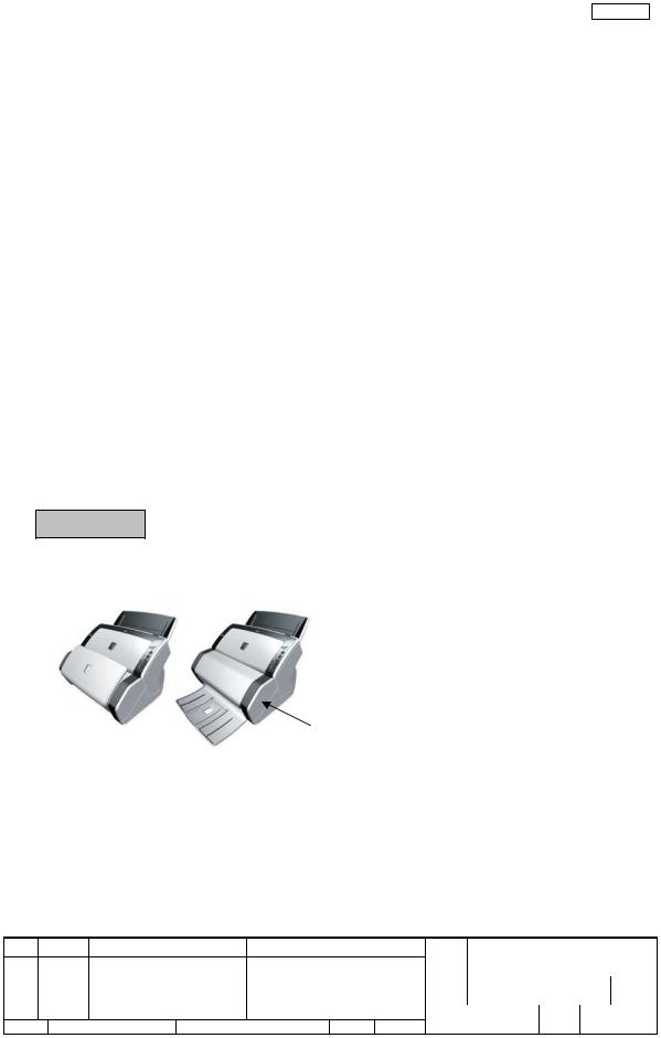
fi-6140/fi-6130
An exclusive imprinter (fi-614PR, option) can be installed under fi-6140/fi-6130 as shown in the photo below. See Chapter 8 for the details of the imprinter.
 Scanner
Imprinter
08 |
July 27, 09 |
K.Okada |
A.Miyoshi |
I.Fujioka |
Refer to Revision Record on page 2. |
|
07 |
Nov.12, 08 |
K.Okada |
T.Anzai |
I.Fujioka |
Refer to Revision Record on page 2. |
|
06 |
Mar.10, 08 |
K.Okada |
T.Anzai |
I.Fujioka |
Refer to Revision Record on page 2. |
|
Rev. |
DATE |
DESIGN |
CHECK |
APPR. |
DESCRIPTION |
|
Design July 27, 2007 K.Okada CHECK K.Okada |
APPR. T.Anzai |
|||||
TITLE |
fi-6140/fi-6240/fi-6130/fi-6230/fi-614PR |
|
Maintenance Manual |
||
DRAW |
P1PA03540-B0XX/6 |
CUST. |
No. |
|
|
PFU LIMITED Page |
10 / 257 |
|
1-1-2 |
Scanner Specifications |
|
|
Section 1-1-2 |
||
Specifications |
|
|||||
No. |
Items |
|
|
|
||
|
fi-6140 |
fi-6130 |
fi-6240 |
fi-6230 |
||
|
|
|
||||
1 |
Operating method |
|
Automatic Document Feeder (ADF) |
Automatic Document |
Feeder (ADF) and |
|
|
Flatbed (FB) |
|
||||
|
|
|
|
|
|
|
2 |
Optical resolution |
|
600 dpi |
|
|
|
|
|
|
Binary: 50 – 600dpi (unit: 1dpi), 1200dpi (by driver) |
|
||
3 |
Output resolution |
|
Gray: 50 – 600 dpi (unit: 1dpi), 1200dpi (by driver) |
|
||
|
|
|
Color: 50 – 600 dpi (unit: 1dpi), 1200dpi (by driver) |
|
||
|
|
|
Color 24 bit/pixel, 8 bit/pixel (by driver), 4 bit/pixel (by driver) |
|
||
4 |
Bit depth |
|
Gray 8 bit/pixel, 4 bit/pixel (by driver) |
|
|
|
|
|
|
Binary 1 bit |
|
|
|
|
|
|
Simplex/Duplex |
Simplex/Duplex |
Simplex/Duplex |
Simplex/Duplex |
|
Scanning speed |
60 ppm / 120 ipm |
40 ppm / 80 ipm |
60 ppm / 120 ipm |
40 ppm / 80 ipm |
|
5 |
(Engine speed) |
|
05 |
|
05 |
|
|
@A4, 200dpi |
40 ppm / 80 ipm |
30 ppm / 60 ipm |
40 ppm / 80 ipm |
30 ppm / 60 ipm |
|
|
|
|
||||
|
|
|
Max: A4 (210 x 297 mm) or Legal (216 x 355.6 mm / 8.50 x 14 in.) |
|
||
6 |
Document size |
Up to 3045 3048 mm (120 in.) of long page scanning is available. |
||||
|
|
|
Min: A8 (53 52 x 74 mm) Portrait / Landscape 07 |
|
||
7 |
Paper weight |
|
0.05 ~ 0.26 mm (41 ~ 210 g/m2, 9.4 ~ 56 lbs) |
|
||
|
A8 size: 0.15 ~ 0.26 mm (127 ~ 210 g/m2) |
|
|
|||
|
|
|
Available, Portrait/Landscape feeding, |
|
|
|
|
|
|
Continuous feeding (up to 3 sheets of continuous feeding) |
|
||
8 |
Card transport |
Thickness: 1.4mm or less |
|
|
||
|
|
|
(fi-6140/fi-6240 models: Monochrome, 200dpi or smaller, Landscape, Card thickness: |
|||
|
|
|
1.25mm or smaller) |
05 |
|
|
9 |
Capacity of ADF |
50 sheets @ A4, 80g/m2 or 20lb |
|
|
||
10 |
Background |
|
Selectable (black or white) |
|
|
|
11 |
Multi |
feed |
Ultrasonic sensor and paper detection sensor |
|
|
|
detection |
|
Document overlapping and document length detection |
|
|||
|
|
|
||||
12 |
Document size |
|
--- |
Maximum: 216 x 297mm / 8.5 x 11.7 in. |
||
13 |
Scanning time |
|
--- |
Binary/Gray/Color: approx.1.7 sec. |
||
|
@A4 Portrait, 200dpi |
|
||||
|
|
|
|
|
|
|
14 |
background |
|
|
--- |
White (Option: black) |
|
15 |
Scanning sensor |
|
Color CCD x 2 |
|
Color CCD x 3 |
|
16 |
Light source |
|
White cold cathode discharge lamp x2 |
White cold cathode discharge lamp x3 |
||
17 |
Interface |
|
Ultra SCSI (x1) |
USB 2.0 (x1) |
Ultra SCSI (x1) |
USB 2.0 (x1) |
|
USB 2.0 (x1) |
USB 2.0 (x1) |
||||
|
|
|
|
|
||
18 |
Image memory |
|
256 MB |
64 MB |
256 MB |
64 MB |
19 |
Attached driver |
|
FJ TWAIN / ISIS, ScandAll PRO, Adobe Acrobat, |
|
||
|
QuickScan Pro.Demo (Trial), Image processing software option (Trial) |
|||||
|
|
|
||||
20 |
Operator panel |
|
Buttons: Function, Send to, Scan/Stop, Power |
|
||
|
Lamps: Check LED, Power LED, Scanner status (Function No. Display) |
|||||
|
|
|
||||
21 |
Supported Options |
|
fi-614PR Imprinter |
|
Black document pad |
05 |
08 |
July 27, 09 |
K.Okada |
A.Miyoshi |
I.Fujioka |
Refer to Revision Record on page 2. |
|
07 |
Nov.12, 08 |
K.Okada |
T.Anzai |
I.Fujioka |
Refer to Revision Record on page 2. |
|
06 |
Mar.10, 08 |
K.Okada |
T.Anzai |
I.Fujioka |
Refer to Revision Record on page 2. |
|
Rev. |
DATE |
DESIGN |
CHECK |
APPR. |
DESCRIPTION |
|
Design July 27, 2007 K.Okada CHECK K.Okada |
APPR. T.Anzai |
|||||
TITLE |
fi-6140/fi-6240/fi-6130/fi-6230/fi-614PR |
|
Maintenance Manual |
||
DRAW |
P1PA03540-B0XX/6 |
CUST. |
No. |
|
|
PFU LIMITED Page |
11 / 257 |
|

1-1-3 |
Environmental Specifications |
|
|
|
Section 1-1-3 |
||
Specifications |
|
||||||
No. |
|
Items |
|
|
|||
|
fi-6140 |
fi-6130 |
|
fi-6240 |
fi-6230 |
||
|
|
|
|
||||
1 |
Input |
Voltage |
|
|
100 to 240V |
|
|
power |
Frequency |
|
|
50/60 Hz |
|
||
|
|
|
|
||||
2 |
Power consumption |
42 W or less |
38 W or less |
|
50 W or less |
45W or less |
|
(Rated power) |
|
||||||
|
|
|
|
|
|
||
3 |
|
Noise |
|
50 dB or less (excluding operator’s area) |
|
||
|
Outer dimensions |
301 (W) x 160 (D) x 158 (H) mm |
|
301 (W) x 567 (D) x 229 (H) mm |
|||
4 |
(Without ADF paper |
|
|||||
11.8 (W) x 6.3 (D) x 6.2 (H) inch |
|
11.8 (W) x 22.3 (D) x 9.0 (H) inch |
|||||
|
Chute and Stacker Unit) |
|
|||||
|
|
|
|
|
|
||
5 |
|
Weight |
4.2kg (9.3 lb) |
|
8.8kg (19.4 lb) |
||
6 |
Ambient |
Temperature |
5 to 35 oC / 41 to 95 oF (Operating) |
-20 to 60 oC / -4 to 140 oF (Not operating) |
|||
condition |
Humidity |
|
20 to 80 % (Operating) |
8 to 95 % (Not operating) |
|
||
|
|
|
|||||
|
|
|
|
||||
7 |
Calorific value 05 |
36.2 kcal/H |
37.7 kcal/H |
|
43.0 kcal/H or |
38.7 kcal/H |
|
or less |
or less |
|
less |
or less |
|||
|
|
|
|
||||
8 |
Weight at shipping |
|
6.5 kg |
|
13.0 kg |
|
|
08 |
July 27, 09 |
K.Okada |
A.Miyoshi |
I.Fujioka |
Refer to Revision Record on page 2. |
|
07 |
Nov.12, 08 |
K.Okada |
T.Anzai |
I.Fujioka |
Refer to Revision Record on page 2. |
|
06 |
Mar.10, 08 |
K.Okada |
T.Anzai |
I.Fujioka |
Refer to Revision Record on page 2. |
|
Rev. |
DATE |
DESIGN |
CHECK |
APPR. |
DESCRIPTION |
|
Design July 27, 2007 K.Okada CHECK K.Okada |
APPR. T.Anzai |
|||||
TITLE |
fi-6140/fi-6240/fi-6130/fi-6230/fi-614PR |
|
Maintenance Manual |
||
DRAW |
P1PA03540-B0XX/6 |
CUST. |
No. |
|
|
PFU LIMITED Page |
12 / 257 |
|
Section 1-1-4
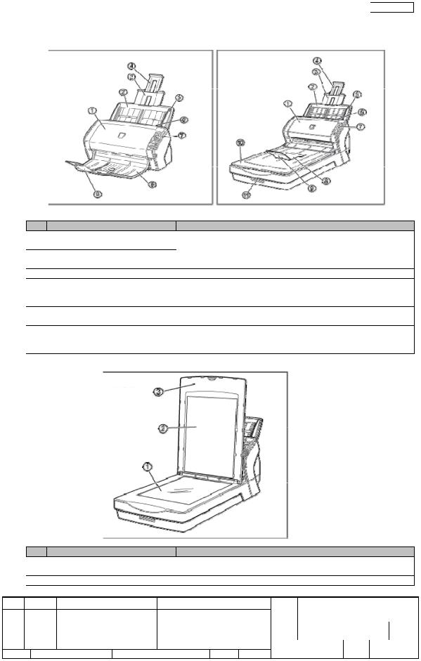
1-1-4 Appearance
[Front]
fi-6140/fi-6130 |
fi-6240/fi-6230 |
No. |
Parts name |
Function |
|
1 |
ADF (Automatic Document Feeder) |
Transports the documents to the reading position automatically. |
|
2 |
ADF Paper Chute (Chute Unit) |
Holds in place the document pages / sheets that are fed into the ADF. |
|
3 |
Paper chute extension 1 |
||
4 |
Paper chute extension 2 |
|
|
5 |
Side Guide |
Adjusted to the width of the paper in order not to scan skewed pages. |
|
6 |
ADF open lever |
Pull this lever toward you to open the ADF. |
|
7 |
Operator Panel |
This panel consists of a Function No. Display, four operating push |
|
buttons, and a LED. |
|||
8 |
Stacker |
||
Scanned documents are ejected from the ADF onto this stacker. |
|||
9 |
Stacker extension |
||
|
|||
10 |
Flatbed (FB) [fi-6240/fi-6230 only] |
Place documents on the glass sheet by sheet for single-sheet scanning. |
|
11 |
Transport lock switch |
Used to lock the carrier unit inside the flatbed during transportation. |
|
[fi-6240/fi-6230 only] |
|||
|
|
[Inside]
fi-6240/fi-6230
No. |
Parts name |
Function |
1 |
Document bed |
Place documents on the glass when scanning through the flatbed. |
2 |
Document holding pad |
Holds documents down on the document bed. |
3 |
Document cover |
Holds the document loaded at the reading position when closed. |
08 |
July 27, 09 |
K.Okada |
A.Miyoshi |
I.Fujioka |
Refer to Revision Record on page 2. |
|
07 |
Nov.12, 08 |
K.Okada |
T.Anzai |
I.Fujioka |
Refer to Revision Record on page 2. |
|
06 |
Mar.10, 08 |
K.Okada |
T.Anzai |
I.Fujioka |
Refer to Revision Record on page 2. |
|
Rev. |
DATE |
DESIGN |
CHECK |
APPR. |
DESCRIPTION |
|
Design July 27, 2007 K.Okada CHECK K.Okada |
APPR. T.Anzai |
|||||
TITLE |
fi-6140/fi-6240/fi-6130/fi-6230/fi-614PR |
|
Maintenance Manual |
||
DRAW |
P1PA03540-B0XX/6 |
CUST. |
No. |
|
|
PFU LIMITED Page |
13 / 257 |
|
Section 1-1-4
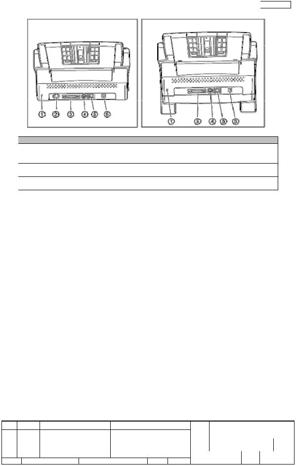
[Rear]
fi-6140/fi-6130 |
fi-6240/fi-6230 |
No. |
Parts name |
Function |
1 |
Security sot |
Attaches the antitheft chain |
2 |
EXT connector (for imprinter) |
Connects the cable from the Imprinter. |
|
[fi-6140/fi-6130 only] |
|
3 |
SCSI connector |
Connects the SCSI interface cable from the host system. |
4 |
SCSI ID switch |
Sets the SCSI ID. (default setting: SCSI ID=5) |
5 |
USB connector |
Connects the USB cable from the host system. |
6 |
DC inlet |
Connects the AC Adapter. |
08 |
July 27, 09 |
K.Okada |
A.Miyoshi |
I.Fujioka |
Refer to Revision Record on page 2. |
|
07 |
Nov.12, 08 |
K.Okada |
T.Anzai |
I.Fujioka |
Refer to Revision Record on page 2. |
|
06 |
Mar.10, 08 |
K.Okada |
T.Anzai |
I.Fujioka |
Refer to Revision Record on page 2. |
|
Rev. |
DATE |
DESIGN |
CHECK |
APPR. |
DESCRIPTION |
|
Design July 27, 2007 K.Okada CHECK K.Okada |
APPR. T.Anzai |
|||||
TITLE |
fi-6140/fi-6240/fi-6130/fi-6230/fi-614PR |
|
Maintenance Manual |
||
DRAW |
P1PA03540-B0XX/6 |
CUST. |
No. |
|
|
PFU LIMITED Page |
14 / 257 |
|

Section 1-1-4
[Operator Panel]
No. |
Name |
Function |
2 |
Check LED |
Lights when an error occurs. |
1 |
Function Number Display |
Indicates the function number and error status. |
3 |
[Function] button |
Changes the Function activated by the [Send to] button. |
4 |
[Send to] button |
Launches the linked application software. Resets an error. |
|
[Scan / Stop] button |
Launches the linked application software. |
5 |
|
Resets and error. |
|
|
Cancels ongoing scanning. |
6 |
Power button / LED |
Turns the scanner ON and OFF. |
|
Lights when the scanner is turned ON. |
|
|
|
08 |
July 27, 09 |
K.Okada |
A.Miyoshi |
I.Fujioka |
Refer to Revision Record on page 2. |
|
07 |
Nov.12, 08 |
K.Okada |
T.Anzai |
I.Fujioka |
Refer to Revision Record on page 2. |
|
06 |
Mar.10, 08 |
K.Okada |
T.Anzai |
I.Fujioka |
Refer to Revision Record on page 2. |
|
Rev. |
DATE |
DESIGN |
CHECK |
APPR. |
DESCRIPTION |
|
Design July 27, 2007 K.Okada CHECK K.Okada |
APPR. T.Anzai |
|||||
TITLE |
fi-6140/fi-6240/fi-6130/fi-6230/fi-614PR |
|
Maintenance Manual |
||
DRAW |
P1PA03540-B0XX/6 |
CUST. |
No. |
|
|
PFU LIMITED Page |
15 / 257 |
|
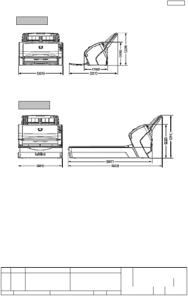
ection 1-1-5
1-1-5 Outer Dimensions
fi-6140/fi-6130
fi-6240/fi-6230
08 |
July 27, 09 |
K.Okada |
A.Miyoshi |
I.Fujioka |
Refer to Revision Record on page 2. |
|
07 |
Nov.12, 08 |
K.Okada |
T.Anzai |
I.Fujioka |
Refer to Revision Record on page 2. |
|
06 |
Mar.10, 08 |
K.Okada |
T.Anzai |
I.Fujioka |
Refer to Revision Record on page 2. |
|
Rev. |
DATE |
DESIGN |
CHECK |
APPR. |
DESCRIPTION |
|
Design July 27, 2007 K.Okada CHECK K.Okada |
APPR. T.Anzai |
|||||
(Unit: mm)
TITLE |
fi-6140/fi-6240/fi-6130/fi-6230/fi-614PR |
|
Maintenance Manual |
||
DRAW |
P1PA03540-B0XX/6 |
CUST. |
No. |
|
|
PFU LIMITED Page |
16 / 257 |
|
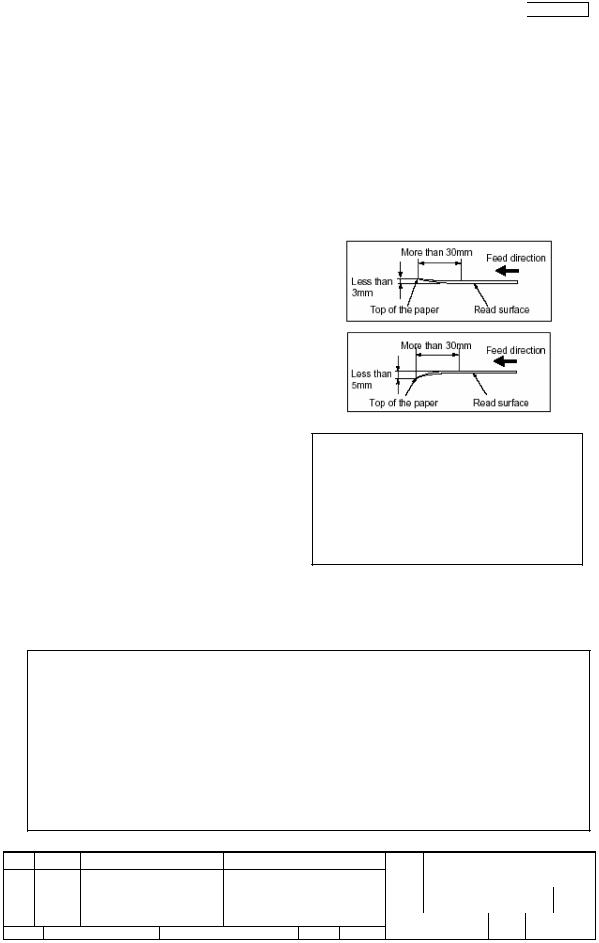
Section 1-1-6
1-1-6 Document Specifications
- Document Type
The following paper types are recommended for document use:
-Woodfree paper
-Wood containing paper
When using documents of paper type other than the above, check whether or not the document can be scanned by test-scanning a few sheets before executing the actual document.
Any other paper types of documents can be scanned through the Flatbed.
- Document Thickness
Paper thickness is expressed by “paper weight”. The following shows the paper weights that can be used on this scanner: 0.05~0.26mm, 41~210 g/m2
Only paper weight of 127 to 210 g/m2 is acceptable for
A8-size documents.
- Precautions
The following documents may not be scanned successfully.
- Documents of non-uniform thickness (e.g. envelopes and
photo-attached documents)
- Wrinkled or curled documents (See right figure) - Folded or torn documents
- Tracing paper
- Coated paper
- Carbon paper
- Photosensitive paper |
|
|
Note: - When scanning semi-transparent documents, |
||
- Perforated documents |
bar to light to |
avoid |
slide the [Brightness] |
||
- Documents that are not square or rectangular |
|
|
bleed through. |
|
|
- Very thin documents |
from becoming |
dirty, |
- To prevent the rollers |
||
- Photographs |
|
|
avoid scanning documents containing large |
||
areas written or filled in pencil. If scanning of |
||
such document is inevitable, clean the rollers |
||
Do not use the following documents: |
|
|
more frequently. |
|
|
-Paper-clipped or stapled documents
-Documents on which the ink is still wet
-Documents smaller than A8 (Portrait) in size
-Documents wider than A4 or Letter size (216mm)
-Documents other than paper such as fabric, metal foil, or transparencies
-Important documents such as certificate and cash vouchers that must not get scratched or become smeared
Note: - Carbonless paper contains chemical substances that may harm the Brake roller or paper feeding rollers (e.g. Pick roller) when documents are fed. Pay attention to the following:
Cleaning: If document jams occur frequently, clean the Brake roller and the Pick roller, by referring Section
7-2-1.
Replacing parts: The service life of the Brake roller and the Pick roller may be shortened compared to that of the rollers used for scanning wood containing paper documents.
-If paper containing wood is scanned, the service life of the Brake roller and the Pick roller may become shorter than that of the rollers used for scanning only woodfree paper.
-The Brake roller or Pick rollers of the scanner could be damaged if photographs or sheets of paper attached to the scanned document have contact with the Brake or Pick rollers during scanning.
-Scanning documents of calendered paper such as photographs may damage the surface of them.
08 |
July 27, 09 |
K.Okada |
A.Miyoshi |
I.Fujioka |
Refer to Revision Record on page 2. |
|
07 |
Nov.12, 08 |
K.Okada |
T.Anzai |
I.Fujioka |
Refer to Revision Record on page 2. |
|
06 |
Mar.10, 08 |
K.Okada |
T.Anzai |
I.Fujioka |
Refer to Revision Record on page 2. |
|
Rev. |
DATE |
DESIGN |
CHECK |
APPR. |
DESCRIPTION |
|
Design July 27, 2007 K.Okada CHECK K.Okada |
APPR. T.Anzai |
|||||
TITLE |
fi-6140/fi-6240/fi-6130/fi-6230/fi-614PR |
|
Maintenance Manual |
||
DRAW |
P1PA03540-B0XX/6 |
CUST. |
No. |
|
|
PFU LIMITED Page |
17 / 257 |
|
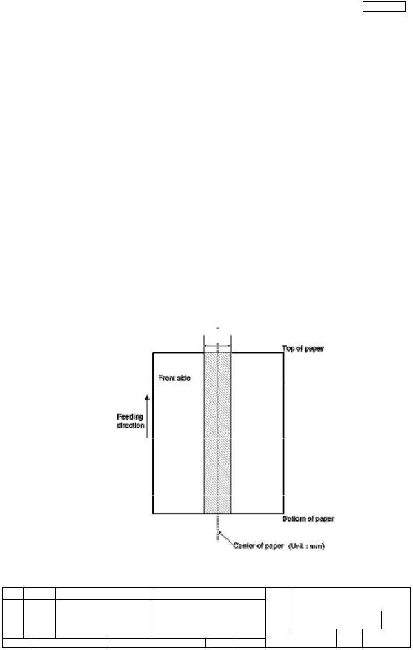
Section 1-1-7
1-1-7 Multi feed Detection Condition
One of the following method of multi feed detection is selected by the driver.
-Check overlapping
-Check length
-Check overlapping and length
The following condition is required for each selection:
1) Check overlapping
- |
Paper weight: 0.05 – 0.26 mm, 41~210 g/m2 |
- |
Punched holes are not allowed within 35 mm (2.12 in) of the vertical centerline of the document. |
- |
Other paper shall not be glued within 35 mm (2.12 in) of the vertical centerline of the document. |
2) Check length |
|
- |
Document length deviation: 1 % or less |
- |
Punched holes are not allowed within 35 mm (2.12 in) of the vertical centerline of the document. |
3) Check overlapping and length
-Paper weight: 0.05 – 0.26 mm, 41~210 g/m2
-Document length deviation: 1 % or less
-Punched holes are not allowed within 35 mm (2.12 in) of the vertical centerline of the document.
-Other paper shall not be glued within 35 mm (2.12 in) of the vertical centerline of the document.
When the overlapping check is specified, the papers which contact closely each other, such as glued paper or electro-statically charged paper, can result in the miss-detection of multi feed.
Multifeed detection monitoring area
35
08 |
July 27, 09 |
K.Okada |
A.Miyoshi |
I.Fujioka |
Refer to Revision Record on page 2. |
|
07 |
Nov.12, 08 |
K.Okada |
T.Anzai |
I.Fujioka |
Refer to Revision Record on page 2. |
|
06 |
Mar.10, 08 |
K.Okada |
T.Anzai |
I.Fujioka |
Refer to Revision Record on page 2. |
|
Rev. |
DATE |
DESIGN |
CHECK |
APPR. |
DESCRIPTION |
|
Design July 27, 2007 K.Okada CHECK K.Okada |
APPR. T.Anzai |
|||||
TITLE |
fi-6140/fi-6240/fi-6130/fi-6230/fi-614PR |
|
Maintenance Manual |
||
DRAW |
P1PA03540-B0XX/6 |
CUST. |
No. |
|
|
PFU LIMITED Page |
18 / 257 |
|
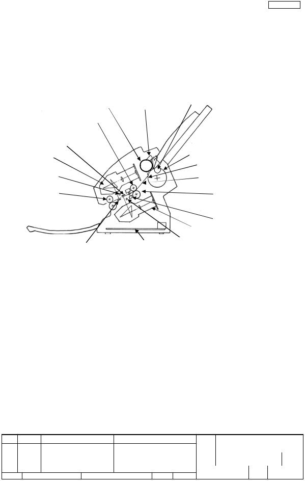
Section 1-2-1
1-2 Scanner Configuration
1-2-1 ADF Unit
(1) Paper separation
When scanning with the ADF, documents loaded on the ADF paper chute (Chute Unit) are separated respectively by the Pick rollers and Brake rollers and fed into the ADF. Separated documents are transported by the feed rollers at the speed that corresponds to specified reading resolution until they are ejected to the stacker.
Paper feeding unit includes Hopper empty sensor (Sensor EMP), PICK sensor, TOP sensor, Multi feed sensor (US Sensor), Paper protection roller (fi-6140/fi-6240 only) and Cover Open Sensor.
Hopper empty sensor Paper protection roller (fi-6140/fi-6240 only)
Brake roller
(Sensor EMP)
Feed roller
Background for front
OPT Unit
Lamp (back)
Eject roller
Background for backside |
Control PCA |
|
(2) Consumables
The Pick roller and Brake roller are consumables and need to be replaced by a user. (Refer to Section 7-3 for detail.)
The scanner supports two consumable counters, Pick roller counter and Brake roller counter, which indicate the number of sheets that have been scanned so far. Users can check the counters from the driver screen or scanner built-in Maintenance mode, and reset the counter after replacing the consumables. (See Section 6-1-6 for details.)
(3) Drive unit
The Pick rollers are driven by the PICK Motor. The Brake rollers, Feed rollers, and Eject rollers are turned by the ADF Motor. The PICK Motor and ADF Motor are controlled separately. This can widen the gap between documents and extend the amount of overscan while overscanning.
The motor drive circuit and motor fuse are located in the Control PCA. If abnormal electric current runs through the motor drive circuit, the current is cut off by the motor fuse in the Control PCA.
08 |
July 27, 09 |
K.Okada |
A.Miyoshi |
I.Fujioka |
Refer to Revision Record on page 2. |
|
07 |
Nov.12, 08 |
K.Okada |
T.Anzai |
I.Fujioka |
Refer to Revision Record on page 2. |
|
06 |
Mar.10, 08 |
K.Okada |
T.Anzai |
I.Fujioka |
Refer to Revision Record on page 2. |
|
Rev. |
DATE |
DESIGN |
CHECK |
APPR. |
DESCRIPTION |
|
Design July 27, 2007 K.Okada CHECK K.Okada |
APPR. T.Anzai |
|||||
TITLE |
fi-6140/fi-6240/fi-6130/fi-6230/fi-614PR |
|
Maintenance Manual |
||
DRAW |
P1PA03540-B0XX/6 |
CUST. |
No. |
|
|
PFU LIMITED Page |
19 / 257 |
|

Section 1-2-2
1-2-2 Reading Station
(1) ADF optical system
Documents are set in the ADF paper chute (Chuter Unit) facing front side down. The front side of a document is scanned by the Optical Unit in the Base Unit, and the backside of a document is scanned by the Optical Unit in the Upper Unit. These two Optical Units have the same part number.
An image on a document is projected to a color CCD through lens and mirror system and converted to signals with 10 bit per pixel at 600 dpi resolution.
(2) FB optical system fi-6240/fi-6230
When FB scanning is specified, a document set on the document bed (glass) is scanned by the Optical Unit of the Carrier unit, which moves in the direction of sub scanning.
The Carrier unit also includes the Lamp and the Inverter to illuminate the document. The Optical Unit, Lamp and Inverter used in FB are the same type as those used in ADF.
(3) FB scanning control fi-6240/fi-6230
During initial processing immediately after power-on, the Carrier unit moves to the home position (the opposite side of ADF). When FB scanning is specified, the scanner moves the Carrier unit to scan the white reference in FB and then adjust the gain of CCD amplifier as a result of scanning the white reference. At that time, if the CCD output does not reach the standard level even after increasing the gain to the maximum level, an optical alarm occurs.
After successful gain adjustment, the scanner scans the specified length of the document while shifting the Carrier unit in the sub scanning direction at the speed that corresponds to the specified scanning resolution. If abnormal electric current runs through the FB Motor, the current is cut off by the motor fuse (the same type as that used in ADF) in Control PCA.
(4) Light source
The scanner uses three Lamps (Incandescent fluorescent lamp) which illuminate the scanning areas in order to get sufficient CCD output. The Lamps are turned ON/OFF by the Inverters that are controlled by the Control PCA.
The life of a Lamp is about 10,000 hours, which means the Lamp lasts during the life of device and is not a consumable.
08 |
July 27, 09 |
K.Okada |
A.Miyoshi |
I.Fujioka |
Refer to Revision Record on page 2. |
|
07 |
Nov.12, 08 |
K.Okada |
T.Anzai |
I.Fujioka |
Refer to Revision Record on page 2. |
|
06 |
Mar.10, 08 |
K.Okada |
T.Anzai |
I.Fujioka |
Refer to Revision Record on page 2. |
|
Rev. |
DATE |
DESIGN |
CHECK |
APPR. |
DESCRIPTION |
|
Design July 27, 2007 K.Okada CHECK K.Okada |
APPR. T.Anzai |
|||||
TITLE |
fi-6140/fi-6240/fi-6130/fi-6230/fi-614PR |
|
Maintenance Manual |
||
DRAW |
P1PA03540-B0XX/6 |
CUST. |
No. |
|
|
PFU LIMITED Page |
20 / 257 |
|
Section 1-2-2
(5) Scan controller
Before scanning a document, the scanner scans white background of the scanning area and adjusts the gain of CCD amplifier. If the CCD output does not reach a certain level after the gain adjustment, Optical alarm is issued.
White
255
Standard output
Low output
Optical alarm
Initial output
0
Pixel
Black Left edge Right edge
Center
When the gain adjustment completes successfully, the scanner feeds the document to the scanning area at the speed that corresponds to specified scanning resolution. Then the leading edge of the document is detected by the TOP sensor in front of the scanning area. After the document is fed from TOP sensor by some defined length for front and back side scanning (the length which determines sub-scanning offset), the scanner starts scanning the image. The scanner terminates scan operation when the length specified from the host is scanned (Fixed size scanning) or when the TOP sensor detects the trailing edge of a document (Page end detection scanning).
08 |
July 27, 09 |
K.Okada |
A.Miyoshi |
I.Fujioka |
Refer to Revision Record on page 2. |
|
07 |
Nov.12, 08 |
K.Okada |
T.Anzai |
I.Fujioka |
Refer to Revision Record on page 2. |
|
06 |
Mar.10, 08 |
K.Okada |
T.Anzai |
I.Fujioka |
Refer to Revision Record on page 2. |
|
Rev. |
DATE |
DESIGN |
CHECK |
APPR. |
DESCRIPTION |
|
Design July 27, 2007 K.Okada CHECK K.Okada |
APPR. T.Anzai |
|||||
TITLE |
fi-6140/fi-6240/fi-6130/fi-6230/fi-614PR |
|
Maintenance Manual |
||
DRAW |
P1PA03540-B0XX/6 |
CUST. |
No. |
|
|
PFU LIMITED Page |
21 / 257 |
|

Section 1-2-3
1-2-3 Controller
(1) Control PCA
Control PCA controls the units shown in the figure below. It includes the following connectors and a switch.
■SCSI connector (fi-6140/fi-6240 only)
■USB connector
■DC voltage input connector
■SCSI ID setting rotary switch
If both SCSI and USB cables are connected,
-SCSI is selected when selection phase is recognized first.
-USB is selected when H level VBUS signal is detected first.
The firmware can be updated through a SCSI/USB interface using firmware update tool.
fi-6140/fi-6130 |
|
|
|
|
|
|
ADF Front |
(600 dpi) |
White |
|
Monochrome |
Image |
|
CCD |
Amp |
Level |
|
|
Fixed |
Memory |
|
|
Memory |
|
|
|
|
|
|
|
|
|
Threshold |
|
|
(1024 levels) |
|
|
|
Dither / |
Image |
|
|
|
Pre-processing |
|
||
|
ADC |
White |
|
Error diffusion |
Memory |
|
ADF Back |
Level |
Emphasis |
|
|
Control |
|
|
Control |
Moire removal |
|
Simplified |
|
|
CCD |
Amp |
|
LUT conversion |
|
Dynamic |
|
|
(600 dpi) |
|
|
|
Threshold |
|
|
|
|
|
Grayscale |
|
|
|
|
|
|
|
Dropout color |
|
|
|
|
|
|
selection |
|
|
Imprinter (option) |
|
|
Color |
|
|
|
|
|
|
|
||
|
Operator Panel |
|
|
|
JPEG compression |
|
|
EEPROM |
|
|
|
|
|
ADF Sensors |
|
CCD |
Timer |
Interrupts |
|
|
|
Controller |
|
Controller |
|
||
|
Controller |
|
USB |
|||
PICK Motor |
|
|
|
|
||
|
Motor |
|
Micro Processor |
SCSI * |
||
ADF Motor |
|
|
|
|
||
|
Driver |
|
|
|
|
|
BW Motor |
|
|
|
|
|
|
*only fi-6140 has SCSI.
08 |
July 27, 09 |
K.Okada |
A.Miyoshi |
I.Fujioka |
Refer to Revision Record on page 2. |
|
07 |
Nov.12, 08 |
K.Okada |
T.Anzai |
I.Fujioka |
Refer to Revision Record on page 2. |
|
06 |
Mar.10, 08 |
K.Okada |
T.Anzai |
I.Fujioka |
Refer to Revision Record on page 2. |
|
Rev. |
DATE |
DESIGN |
CHECK |
APPR. |
DESCRIPTION |
|
Design July 27, 2007 K.Okada CHECK K.Okada |
APPR. T.Anzai |
|||||
TITLE |
fi-6140/fi-6240/fi-6130/fi-6230/fi-614PR |
|
Maintenance Manual |
||
DRAW |
P1PA03540-B0XX/6 |
CUST. |
No. |
|
|
PFU LIMITED Page |
22 / 257 |
|
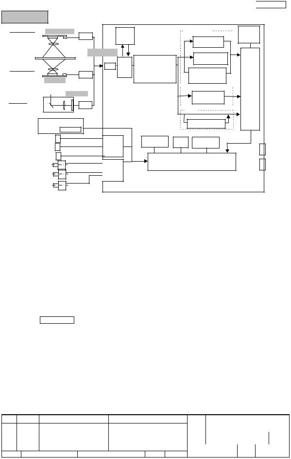
|
|
|
|
|
|
|
Section 1-2-3 |
fi-6240/fi-6230 |
|
|
|
|
|
|
|
ADF Front |
(600 dpi) |
|
White |
|
Monochrome |
Image |
|
|
Amp |
|
Level |
|
|
Fixed |
Memory |
|
|
|
Memory |
|
|
|
|
|
|
|
|
|
|
Threshold |
|
|
(1024 levels) |
|
|
|
Dither / |
Image |
|
|
|
|
|
Pre-processing |
|
Memory |
|
|
|
|
White |
|
Error diffusion |
Control |
|
ADF Back |
|
ADC |
Level |
Emphasis |
|
|
|
|
|
|
|
||||
Amp |
|
Control |
Moire removal |
|
Simplified |
|
|
|
|
|
LUT transmission |
Dynamic |
|
||
|
(600 dpi) |
|
|
|
|
Threshold |
|
|
(600 dpi) |
|
|
|
Grayscale |
|
|
|
|
|
|
|
Dropout color |
|
|
Flatbed |
Amp |
|
|
|
|
selection |
|
|
|
|
|
|
|
||
|
|
|
|
Color |
|
||
|
|
|
|
|
|
||
|
Operator Panel |
|
|
|
|
JPEG |
|
|
EEPROM |
|
|
|
|
|
|
ADF Sensors |
Controller |
CCD |
Timer |
Interrupts |
|
||
FB Home Position Sensor |
Controller |
|
Controller |
|
|||
|
|
|
USB |
||||
|
|
|
|
|
|||
PICK Motor |
|
|
|
|
|
||
|
|
|
Micro Processor |
|
|||
ADF Motor |
|
Motor |
|
SCSI * |
|||
|
|
|
|
||||
FB Motor |
|
Driver |
|
|
|
|
|
|
|
|
|
|
|
|
|
BW Motor |
|
|
|
|
|
|
|
*only fi-6240 has SCSI.
(2) Panel PCA
The Panel PCA in operator panel includes not only the switch and operator panel described in Section 1-1-4, but also EEPROM that records the information below. When replacing the Panel PCA with new one, you need to move all data stored in the EEPROM to the Control PCA, and then return the data from the Control PCA to the new Panel PCA.
■Magnification correction value for main/sub scanning direction
■Offset correction value for main/sub scanning direction
■White level correction value
■Values of Brake roller counter and Pick roller counter
■First date of the scanner operation, ADF scanned number of documents
(3)Joint PCA fi-6240/fi-6230
This is a PCA installed in carrier unit (a unit including Optical Unit, Lamp, Lamp Inverter) of flatbed and used to convert the connector interface among CR Cable, the cable from Optical Unit and Lamp Inverter.
08 |
July 27, 09 |
K.Okada |
A.Miyoshi |
I.Fujioka |
Refer to Revision Record on page 2. |
|
07 |
Nov.12, 08 |
K.Okada |
T.Anzai |
I.Fujioka |
Refer to Revision Record on page 2. |
|
06 |
Mar.10, 08 |
K.Okada |
T.Anzai |
I.Fujioka |
Refer to Revision Record on page 2. |
|
Rev. |
DATE |
DESIGN |
CHECK |
APPR. |
DESCRIPTION |
|
Design July 27, 2007 K.Okada CHECK K.Okada |
APPR. T.Anzai |
|||||
TITLE |
fi-6140/fi-6240/fi-6130/fi-6230/fi-614PR |
|
Maintenance Manual |
||
DRAW |
P1PA03540-B0XX/6 |
CUST. |
No. |
|
|
PFU LIMITED Page |
23 / 257 |
|
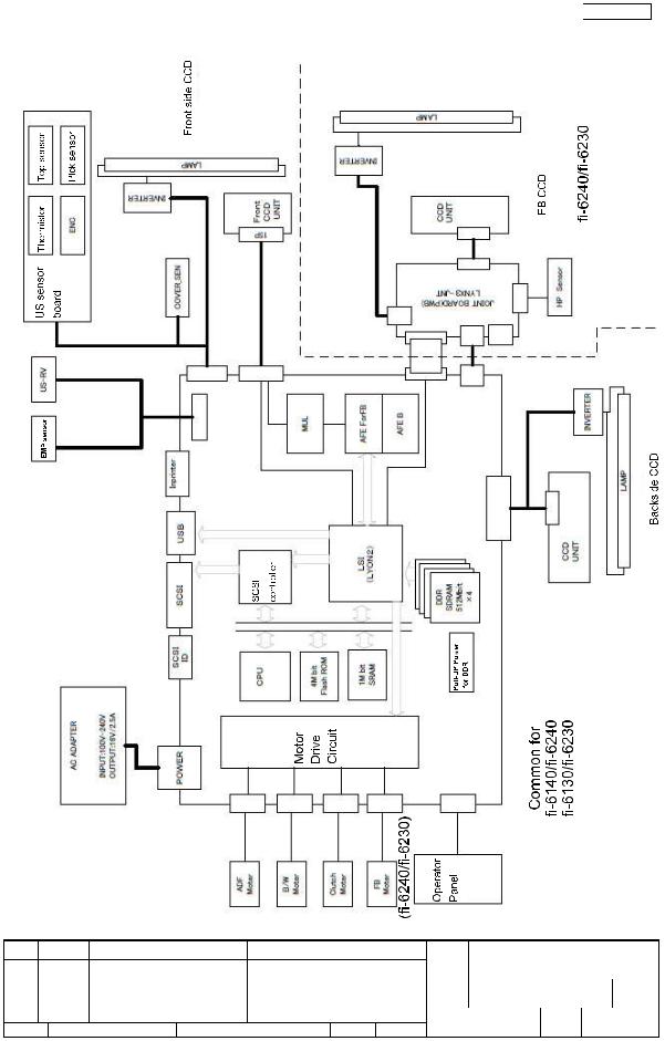
1-2-4 Electric Component Block Diagram
08 |
July 27, 09 |
K.Okada |
A.Miyoshi |
I.Fujioka |
Refer to Revision Record on page 2. |
|
07 |
Nov.12, 08 |
K.Okada |
T.Anzai |
I.Fujioka |
Refer to Revision Record on page 2. |
|
06 |
Mar.10, 08 |
K.Okada |
T.Anzai |
I.Fujioka |
Refer to Revision Record on page 2. |
|
Rev. |
DATE |
DESIGN |
CHECK |
APPR. |
DESCRIPTION |
|
Design July 27, 2007 K.Okada CHECK K.Okada |
APPR. T.Anzai |
|||||
Section 1-2-4
TITLE |
fi-6140/fi-6240/fi-6130/fi-6230/fi-614PR |
|
Maintenance Manual |
||
DRAW |
P1PA03540-B0XX/6 |
CUST. |
No. |
|
|
PFU LIMITED Page |
24 / 257 |
|
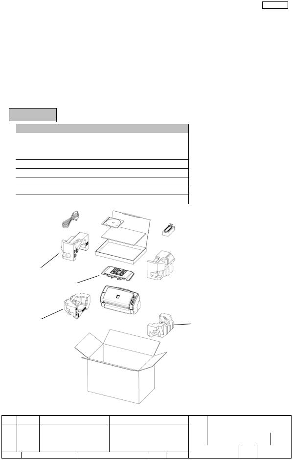
Section 2-1
Chapter 2 Description of Scanner Operation
2-1 Unpacking the scanner
Follow the procedure below to unpack the scanner package. Make sure that all the accessories are included in the package.
1.Remove the tape to open the package box.
2.Take out the CD tray and other accessories.
3.Take out the scanner and cushions. And remove the cushioning materials.
4.Open the polyethylene bag to take out the scanner.
5.Take out all the accessories and remove the tape protecting the scanner.
The following table lists the packaging configuration.
fi-6140/fi-6130
No. |
Items |
Quantity |
1 |
Package box |
1 |
2 |
CD tray (including accessories) |
1 |
3 |
Cushion TR |
1 |
4 |
Cushion TL |
1 |
5 |
Cushion BR |
1 |
6 |
Cushion BL |
1 |
7 |
Scanner in Polyethylene bag |
1 |
8 |
ADF paper chute (Chute Unit) and other accessories |
1 |
 2. CD Tray
 3. Cushion TR
4.Cushion TL
8. ADF Paper Chute
 7. Scanner
6. Cushion BL |
5. Cushion BR |
 1. Package Box
08 |
July 27, 09 |
K.Okada |
A.Miyoshi |
I.Fujioka |
Refer to Revision Record on page 2. |
|
07 |
Nov.12, 08 |
K.Okada |
T.Anzai |
I.Fujioka |
Refer to Revision Record on page 2. |
|
06 |
Mar.10, 08 |
K.Okada |
T.Anzai |
I.Fujioka |
Refer to Revision Record on page 2. |
|
Rev. |
DATE |
DESIGN |
CHECK |
APPR. |
DESCRIPTION |
|
Design July 27, 2007 K.Okada CHECK K.Okada |
APPR. T.Anzai |
|||||
TITLE |
fi-6140/fi-6240/fi-6130/fi-6230/fi-614PR |
|
Maintenance Manual |
||
DRAW |
P1PA03540-B0XX/6 |
CUST. |
No. |
|
|
PFU LIMITED Page |
25 / 257 |
|
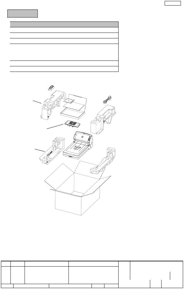
Section 2-1
fi-6240/fi-6230
No. |
Items |
Quantity |
1 |
Package box |
1 |
2 |
CD tray (including accessories) |
1 |
3 |
Cushion TR |
1 |
4 |
Cushion TL |
1 |
5 |
Cushion BR |
1 |
6 |
Cushion BL |
1 |
7 |
Scanner in Polyethylene bag |
1 |
8 |
ADF paper chute (Chute Unit) and other accessories |
1 |
 2. CD Tray
4. Cushion TL
 3. Cushion TR
8. ADF Paper Chute
 7. Scanner
6. Cushion BL
 5. Cushion BR
 1. Package Box
08 |
July 27, 09 |
K.Okada |
A.Miyoshi |
I.Fujioka |
Refer to Revision Record on page 2. |
|
07 |
Nov.12, 08 |
K.Okada |
T.Anzai |
I.Fujioka |
Refer to Revision Record on page 2. |
|
06 |
Mar.10, 08 |
K.Okada |
T.Anzai |
I.Fujioka |
Refer to Revision Record on page 2. |
|
Rev. |
DATE |
DESIGN |
CHECK |
APPR. |
DESCRIPTION |
|
Design July 27, 2007 K.Okada CHECK K.Okada |
APPR. T.Anzai |
|||||
TITLE |
fi-6140/fi-6240/fi-6130/fi-6230/fi-614PR |
|
Maintenance Manual |
||
DRAW |
P1PA03540-B0XX/6 |
CUST. |
No. |
|
|
PFU LIMITED Page |
26 / 257 |
|
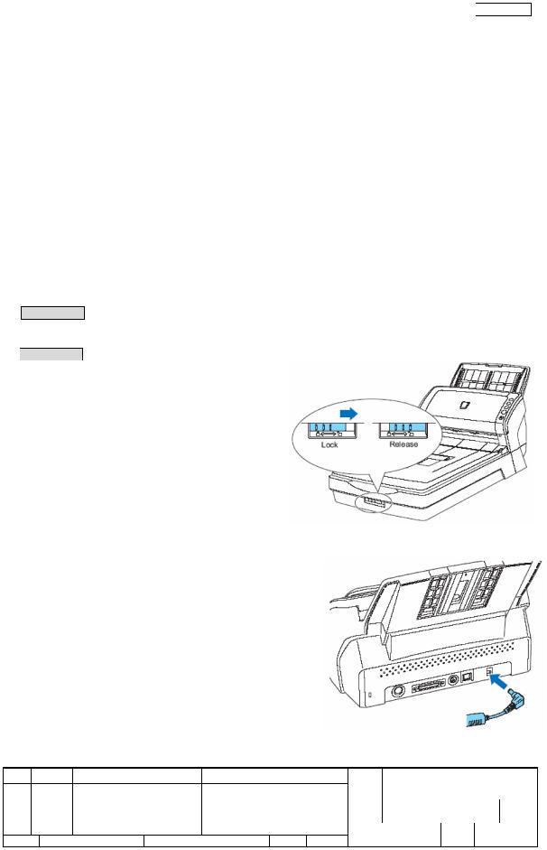
Section 2-2-1
2-2 Installing the scanner
2-2-1 For safety installation
Before installing the scanner, read the following cautions carefully to avoid scanner trouble.
Refer to Section 1-1-3 “Environmental Specifications” for information of power source and scanner dimensions.
■Install the scanner away from strong magnetic fields and other sources of noise.
■Do not install the scanner near heating apparatus or in the direct sunlight.
■Install the scanner in a location which is level and subject to minimal vibration.
■Do not install the scanner in locations subject to humidity and dust.
■Do not block the ventilation ports.
■Protect the scanner from static electricity.
■Use proper AC voltage.
■Make sure the rubber pads on the bottom of the scanner grounds evenly.
2-2-2 Installation
(1)fi-6140/fi-6130 If you wish to install the imprinter (optional), refer to Section 8-3-2 before performing the following procedures.
(2)fi-6240/fi-6230 Unlock the Transport lock.
The carrier unit inside the fi-6240/fi-6230 is fixed in place with the transport lock to prevent the scanner from being damaged during transportation. To unlock the transport lock, slide the transport lock switch on the scanner front.
(3)Referring to Section 5-8-1, attach the ADF paper chute (Chuter Unit).
(4)Connect the AC cable to the AC Adapter.
Note: Use only the supplied AC adapter.
(5)Connect the AC adapter connector to the scanner’s DC inlet. (right figure)
(6)Plug the AC cable into an outlet. If you want to plug it into a two-slot outlet, use the supplied adapter plug.
Notes:
-Before plugging the adapter plug into an outlet, be sure to establish a ground.
-The Function Number Display and LED of the operator panel of the scanner may flash for an instant when the AC cable is plugged into an outlet. This is a phenomenon due to the initial diagnosis, but not a failure.
08 |
July 27, 09 |
K.Okada |
A.Miyoshi |
I.Fujioka |
Refer to Revision Record on page 2. |
|
07 |
Nov.12, 08 |
K.Okada |
T.Anzai |
I.Fujioka |
Refer to Revision Record on page 2. |
|
06 |
Mar.10, 08 |
K.Okada |
T.Anzai |
I.Fujioka |
Refer to Revision Record on page 2. |
|
Rev. |
DATE |
DESIGN |
CHECK |
APPR. |
DESCRIPTION |
|
Design July 27, 2007 K.Okada CHECK K.Okada |
APPR. T.Anzai |
|||||
TITLE |
fi-6140/fi-6240/fi-6130/fi-6230/fi-614PR |
|
Maintenance Manual |
||
DRAW |
P1PA03540-B0XX/6 |
CUST. |
No. |
|
|
PFU LIMITED Page |
27 / 257 |
|
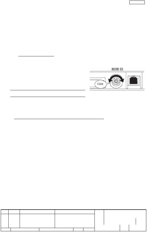
Section 2-2-2
(7) Connect either with the USB cable or the SCSI cable. (fi-6130/fi-6230 has USB cable only.) Note 1: Connect only one of the USB or SCSI cable.
Note 2: Be sure to use the USB cable which comes as an accessory with this scanner. Scanning operation with commercially available cables is not guaranteed.
Note 3: When connecting to a USB hub, use the first stage USB hub that is closest to the computer. If you use the second or later hub stages, the scanner may not operate correctly.
Note 4: If you connect the scanner with USB 2.0, it is required that the USB port and Hub are compliant with USB 2.0. The scanning speed may slow down if it is connected with USB 1.1.
Note 5: When using the scanner with a SCSI interface, the following SCSI cable and SCSI card must be purchased.
- SCSI cable:
Use a cable which complies with a 50 Pin Contact Shielded High-Density SCSI Device Connector for Ultra SCSI.
- SCSI card:
Find the recommended SCSI card information in the Fujitsu web site (FAQ).
http://imagescanner.fujitsu.com/
Note 6: When connecting the SCSI cable, be sure to first connect the SCSI cable, and, then turn on the scanner and the PC. Note 7: In a SCSI daisy chain formation, connect the scanner so that it is the terminated device.
(8) The SCSI ID initially set at the factory is [5]. If the SCSI ID of another SCSI device is set to the same ID, either change the scanner’s SCSI ID or SCSI ID of the other SCSI device. Turn off the scanner, and then set the SCSI ID using the SCSI ID switch on the back of the scanner.
ID No. |
Description |
0 to 7 |
Can be set as the ID |
8, 9 |
Works with the factory default value (SCSI ID=5). |
(9)Press the Power button to turn ON the scanner.
(10)Turn ON the computer.
(11)Install either of the scanner drivers below and ScandAll PRO and Error Recovery Guide.
Scanner drivers: |
Scanning Application: |
- FUJITSU TWAIN 32 |
- ScandAll PRO (Supports both FUJITSU TWAIN 32 and ISIS) |
- FUJITSU ISIS |
|
Information at scanner error: |
|
- Error Recovery Guide |
|
08 |
July 27, 09 |
K.Okada |
A.Miyoshi |
I.Fujioka |
Refer to Revision Record on page 2. |
|
07 |
Nov.12, 08 |
K.Okada |
T.Anzai |
I.Fujioka |
Refer to Revision Record on page 2. |
|
06 |
Mar.10, 08 |
K.Okada |
T.Anzai |
I.Fujioka |
Refer to Revision Record on page 2. |
|
Rev. |
DATE |
DESIGN |
CHECK |
APPR. |
DESCRIPTION |
|
Design July 27, 2007 K.Okada CHECK K.Okada |
APPR. T.Anzai |
|||||
TITLE |
fi-6140/fi-6240/fi-6130/fi-6230/fi-614PR |
|
Maintenance Manual |
||
DRAW |
P1PA03540-B0XX/6 |
CUST. |
No. |
|
|
PFU LIMITED Page |
28 / 257 |
|

|
|
|
|
|
|
|
|
|
Chapter 3 |
|
Chapter 3 Maintenance Parts |
|
|
|
|
|
|
||||
|
|
|
|
Quantity |
|
Ref. for |
Ref. for |
|
||
POS |
Description |
Part Number |
|
|
appear- |
replaceRemarks |
||||
fi-6140 |
fi-6240 |
fi-6130 |
fi-6230 |
|||||||
|
|
|
ance |
ment |
|
|||||
ADF Section |
|
|
|
|
|
|
|
|
||
1 |
BASE UNIT |
PA03540-D941 |
1 |
1 |
|
|
3-1 |
5-9-1 |
|
|
BASE UNIT L |
PA03540-D951 |
|
|
1 |
1 |
|
||||
|
|
|
|
|
|
|||||
2 |
BASE ASSY |
PA03540-E941 |
1 |
1 |
|
|
3-2 |
5-9-2 |
|
|
BASE ASSY L |
PA03540-E951 |
|
|
1 |
1 |
|
||||
|
|
|
|
|
|
|||||
3 |
INVERTER |
PA03540-K910 |
1 |
1 |
1 |
1 |
3-3 |
5-9-3 |
|
|
4 |
LAMP |
PA03540-K911 |
1 |
1 |
1 |
1 |
3-4 |
5-9-4 |
|
|
5 |
US SENSOR FX |
PA03540-K913 |
1 |
1 |
1 |
1 |
3-5 |
5-9-5 |
Multifeed |
|
detection |
||||||||||
|
|
|
|
|
|
|
|
|
||
6 |
OPT UNIT |
PA03540-E903 |
1 |
1 |
1 |
1 |
3-6 |
5-9-6 |
|
|
7 |
BW MOTOR |
PA03540-F901 |
1 |
1 |
1 |
1 |
3-7 |
5-9-7 |
|
|
8 |
GUIDE P ASSY(Sheet guide) |
PA03540-E908 |
1 |
1 |
|
|
3-8 |
5-9-8 |
|
|
GUIDE P ASSY L(Sheet guide) |
PA03540-E909 |
|
|
1 |
1 |
|
||||
|
|
|
|
|
|
|||||
9 |
PICK MOTOR ASSY |
PA03540-F904 |
1 |
1 |
1 |
1 |
3-9 |
5-9-9 |
|
|
10 |
PICK MOTOR |
PA03540-F903 |
1 |
1 |
1 |
1 |
3-10 |
5-9-10 |
|
|
11 |
PICK SHAFT ASSY |
PA03540-F907 |
1 |
1 |
1 |
1 |
3-11 |
5-9-11 |
|
|
12 |
SWITCH |
PA03484-K804 |
1 |
1 |
1 |
1 |
3-12 |
5-9-12 |
ADF open |
|
detection. |
||||||||||
|
|
|
|
|
|
|
|
|
||
|
UPPER UNIT |
PA03540-D961 |
1 |
|
|
|
|
|
*1 |
|
|
UPPER UNIT C |
PA03540-D967 |
|
|
|
|
|
* 2 |
||
|
|
|
|
|
|
|
||||
|
UPPER UNIT |
PA03540-D971 |
|
1 |
|
|
|
|
*1 |
|
13 |
UPPER UNIT C |
PA03540-D977 |
|
|
|
3-13 |
5-10-1 |
*2 |
||
|
|
|
|
|||||||
UPPER UNIT L |
PA03540-D981 |
|
|
|
|
*1 |
||||
|
|
|
1 |
|
|
|
||||
|
UPPER UNIT LC |
PA03540-D987 |
|
|
|
|
|
* 2 |
||
|
|
|
|
|
|
|
||||
|
UPPER UNIT L |
PA03540-D991 |
|
|
|
1 |
|
|
*1 |
|
|
UPPER UNIT LC |
PA03540-D997 |
|
|
|
|
|
*2 |
||
|
|
|
|
|
|
|
||||
14 |
UPPER ASSY |
PA03540-E931 |
1 |
1 |
1 |
1 |
3-14 |
5-10-2 |
|
|
15 |
ADF MOTOR |
PA03540-K915 |
1 |
1 |
1 |
1 |
3-15 |
5-10-3 |
|
|
16 |
OPT UNIT |
PA03540-E903 |
1 |
1 |
1 |
1 |
3-6 |
5-10-4 |
|
|
17 |
INVERTER |
PA03540-K910 |
1 |
1 |
1 |
1 |
3-3 |
5-10-5 |
|
|
18 |
LAMP |
PA03540-K911 |
1 |
1 |
1 |
1 |
3-4 |
5-10-6 |
|
|
19 |
US SENSOR RV |
PA03484-K905 |
1 |
1 |
1 |
1 |
3-19 |
5-10-7 |
Multifeed |
|
detection *3 |
||||||||||
|
|
|
|
|
|
|
|
|
||
20 |
SENSOR EMP |
PA03540-K906 |
1 |
1 |
1 |
1 |
3-20 |
5-10-8 |
Paper empty |
|
detection |
||||||||||
|
|
|
|
|
|
|
|
|
||
21 |
PANEL PCA |
PA03540-K907 |
1 |
1 |
1 |
1 |
3-21 |
5-10-9 |
|
|
22 |
BR SHAFT ASSY |
PA03540-F905 |
1 |
1 |
1 |
1 |
3-22 |
5-10-10 |
|
|
*1: For Europe, North America *2: For China
*3: Shared with fi-5120C/fi-5220C.
08 |
July 27, 09 |
K.Okada |
A.Miyoshi |
I.Fujioka |
Refer to Revision Record on page 2. |
|
07 |
Nov.12, 08 |
K.Okada |
T.Anzai |
I.Fujioka |
Refer to Revision Record on page 2. |
|
06 |
Mar.10, 08 |
K.Okada |
T.Anzai |
I.Fujioka |
Refer to Revision Record on page 2. |
|
Rev. |
DATE |
DESIGN |
CHECK |
APPR. |
DESCRIPTION |
|
Design July 27, 2007 K.Okada CHECK K.Okada |
APPR. T.Anzai |
|||||
TITLE |
fi-6140/fi-6240/fi-6130/fi-6230/fi-614PR |
|
Maintenance Manual |
||
DRAW |
P1PA03540-B0XX/6 |
CUST. |
No. |
|
|
PFU LIMITED Page |
29 / 257 |
|
Chapter 3
Maintenance Parts (Cont’d)
POS |
Description |
Part Number |
|
Quantity |
|
Ref. for |
Ref. for |
||
|
|
appear- |
replace- |
||||||
fi-6140 |
fi-6240 |
fi-6130 |
fi-6230 |
||||||
|
|
|
ance |
ment |
|||||
23 |
CONTROL PCA |
PA03540-K901 |
1 |
|
|
|
|
|
|
PA03540-K917 |
|
1 |
|
|
|
|
|||
|
|
|
|
|
3-23 |
5-11 |
|||
|
|
PA03540-K918 |
|
|
1 |
|
|||
24 |
CONTROL PCA L |
|
|
|
|
|
|||
PA03540-K919 |
|
|
|
1 |
|
|
|||
|
|
|
|
|
|
|
|||
25 |
STACKER UNIT |
PA03540-E904 |
1 |
|
1 |
|
3-25 |
5-8-2 |
|
26 |
CHUTER UNIT |
PA03540-E905 |
1 |
1 |
1 |
1 |
3-26 |
5-8-1 |
|
(ADF paper chute) |
|||||||||
|
|
|
|
|
|
|
|
||
27 |
AC ADAPTER |
PA03334-K920 |
1 |
1 |
1 |
1 |
3-27 |
|
|
|
AC CORDSET E |
PA63083-1831 |
|
|
|
|
|
|
|
28 |
AC CORDSET UK |
PA63098-1831 |
1 |
1 |
1 |
1 |
3-28 |
|
|
AC CORDSET U |
PA63082-1831 |
|
|||||||
|
|
|
|
|
|
|
|||
|
AC CORDSET C |
PA63084-1831 |
|
|
|
|
|
|
|
29 |
USB CABLE |
PA61001-0142 |
1 |
1 |
1 |
1 |
3-29 |
|
|
Flatbed |
|
|
|
|
|
|
|
||
30 |
FB TOP COV ASSY |
PA03540-E961 |
|
1 |
|
1 |
3-30 |
5-12-1 |
|
31 |
FB MOTOR UNIT |
PA03540-E919 |
|
1 |
|
1 |
3-31 |
5-12-2 |
|
32 |
FB MOTOR |
PA03540-E909 |
|
1 |
|
1 |
3-32 |
5-12-3 |
|
PA03540-F90904 |
|
|
|||||||
|
|
|
|
|
|
|
|
||
33 |
OPT BOX UNIT |
PA03540-E910 |
|
1 |
|
1 |
3-33 |
5-12-4 |
|
34 |
OPT UNIT |
PA03540-E903 |
|
1 |
|
1 |
3-6 |
5-12-5 |
|
35 |
INVERTER |
PA03540-K910 |
|
1 |
|
1 |
3-3 |
5-12-6 |
|
36 |
LAMP |
PA03540-K911 |
|
1 |
|
1 |
3-4 |
5-12-7 |
|
37 |
CR CABLE |
PA70002-0928 |
|
1 |
|
1 |
3-37 |
5-12-8 |
|
38 |
DOC COV ASSY |
PA03540-E921 |
|
1 |
|
1 |
3-38 |
5-12-9 |
|
39 |
JOINT PCA |
PA03540-K916 |
|
1 |
|
1 |
3-39 |
5-12-10 |
|
*4: Shared with fi-5530C2 *5: Shared with fi-5220C
Remarks
*4 For Europe
For UK
For North
America
For China
*5
08 |
July 27, 09 |
K.Okada |
A.Miyoshi |
I.Fujioka |
Refer to Revision Record on page 2. |
|
07 |
Nov.12, 08 |
K.Okada |
T.Anzai |
I.Fujioka |
Refer to Revision Record on page 2. |
|
06 |
Mar.10, 08 |
K.Okada |
T.Anzai |
I.Fujioka |
Refer to Revision Record on page 2. |
|
Rev. |
DATE |
DESIGN |
CHECK |
APPR. |
DESCRIPTION |
|
Design July 27, 2007 K.Okada CHECK K.Okada |
APPR. T.Anzai |
|||||
TITLE |
fi-6140/fi-6240/fi-6130/fi-6230/fi-614PR |
|
Maintenance Manual |
||
DRAW |
P1PA03540-B0XX/6 |
CUST. |
No. |
|
|
PFU LIMITED Page |
30 / 257 |
|
 Loading...