


& Service |
GF40 and GF14 |
||
Manual Parts |
Gas Series |
||
|
|
Fryers |
|
|
|
|
|
|
|
|
|
|
|
|
|
Frymaster, a member of the Commercial Food Equipment Service Association, recommends using CFESA Certified Technicians.
24-Hour Service Hotline 1-800-551-8633
819-5888 APR 2002
NOTICE
This appliance is intended for professional use only and is to be operated by qualified personnel only. A Frymaster/DEAN Factory Authorized Service Center (FASC) or other qualified professional should perform installation, maintenance, and repairs. Installation, maintenance, or repairs by unqualified personnel may void the manufacturer’s warranty. See Chapter 1 of this manual for definitions of qualified personnel.
NOTICE
This equipment must be installed in accordance with the appropriate national and local codes of the country and/or region in which the appliance is installed. See NATIONAL CODE REQUIREMENTS in Chapter 2 of this manual for specifics.
NOTICE TO U.S. CUSTOMERS
This equipment is to be installed in compliance with the basic plumbing code of the Building Officials and Code Administrators International, Inc. (BOCA) and the Food Service Sanitation

 Manual of the U.S. Food and Drug Administration.
NOTICE
Drawings and photos used in this manual are intended to illustrate operational, cleaning and technical procedures and may not conform to onsite management operational procedures.
NOTICE TO OWNERS OF UNITS EQUIPPED WITH COMPUTERS
U.S.
This device complies with Part 15 of the FCC rules. Operation is subject to the following two conditions: 1) This device may not cause harmful interference, and 2) This device must accept any interference received, including interference that may cause undesired operation. While this device is a verified Class A device, it has been shown to meet the Class B limits.
CANADA
This digital apparatus does not exceed the Class A or B limits for radio noise emissions as set out by the ICES-003 standard of the Canadian Department of Communications.
Cet appareil numerique n’emet pas de bruits radioelectriques depassany les limites de classe A et B prescrites dans la norme NMB-003 edictee par le Ministre des Communcations du Canada.
 DANGER
Improper installation, adjustment, maintenance or service, and unauthorized alterations or modifications can cause property damage, injury, or death. Read the installation, operating, and service instructions thoroughly before installing or servicing this equipment. Only qualified service personnel may convert this appliance to use a gas other than that for which it was originally configured.
 DANGER
No structural material on the fryer should be altered or removed to accommodate placement of the fryer under a hood. Questions? Call the Frymaster/Dean Service Hotline at 1-800-551-8633.
 DANGER
Adequate means must be provided to limit the movement of this appliance without depending upon the gas line connection. Single fryers equipped with legs must be stabilized by installing anchor straps. All fryers equipped with casters must be stabilized by installing restraining chains. If a flexible gas line is used, an additional restraining cable must be connected at all 
 times when the fryer is in use.

 DANGER
The front ledge of the fryer is not a step! Do not stand on the fryer. Serious injury can result from slips or contact with the hot oil.
 DANGER
Do not store or use gasoline or other flammable liquids or vapors in the vicinity of this or any other appliance.
 DANGER
Instructions to be followed in the event the operator smells gas or otherwise detects a gas leak must be posted in a prominent location. This information can be obtained from the local gas company or gas supplier.
 DANGER
This product contains chemicals known to the state of California to cause cancer and/or birth defects or other reproductive harm.
Operation, installation, and servicing of this product could expose you to airborne particles of glasswool or ceramic fibers, crystalline silica, and/or carbon monoxide. Inhalation of airborne particles of glasswool or ceramic fibers is known to the State of California to cause cancer. Inhalation of carbon monoxide is known to the State of California to cause birth defects or other reproductive harm.

GF14 and GF40 SERIES GAS FRYERS
TABLE OF CONTENTS
CHAPTER 1: Service Procedures |
|
|
1.1 |
Functional Description......................................................................................... |
1-1 |
1.2 |
Accessing Fryers for Servicing ............................................................................ |
1-2 |
1.3 |
Cleaning the Gas Valve Vent Tube...................................................................... |
1-2 |
1.4 |
Calibrating the Operating Thermostat.................................................................. |
1-2 |
1.5 |
Checking the Burner Manifold Pressure .............................................................. |
1-3 |
1.6 |
Adjusting Deflector Spacing and Alignment ....................................................... |
1-3 |
1.7 |
Adjusting the Pilot Flame..................................................................................... |
1-3 |
1.8 |
Replacing Fryer Components............................................................................... |
1-4 |
1.8.1 |
Replacing the Operating Thermostat.................................................................... |
1-4 |
1.8.2 |
Replacing the High-Limit Thermostat ................................................................. |
1-5 |
1.8.3 |
Replacing Deflectors............................................................................................ |
1-5 |
1.8.4 |
Replacing the Gas Valve...................................................................................... |
1-6 |
1.8.5 |
Replacing the Thermopile or Pilot Assembly ...................................................... |
1-7 |
1.8.6 |
Replacing the Frypot ............................................................................................ |
1-8 |
1.9 |
Troubleshooting and Problem Isolation............................................................... |
1-9 |
1.9.1 |
Pilot Failure........................................................................................................... |
1.9 |
1.9.2 |
Improper Burner Functioning............................................................................. |
1-10 |
1.9.3 |
Improper Temperature Control........................................................................... |
1.11 |
1.9.4 |
Leaking................................................................................................................ |
1.11 |
1.10 |
Wiring Diagrams................................................................................................ |
1-12 |
1.10.1 |
Current Production Units with Honeywell Gas Valve....................................... |
1-12 |
1.10.2 |
Early Production Units with Robertshaw Gas Valve......................................... |
1-13 |
CHAPTER 2: GF14 Parts Lists |
|
|
Accessories....................................................................................................................... |
2-1 |
|
Burner and Gas Supply Components ............................................................................... |
2-2 |
|
Cabinetry Components..................................................................................................... |
2-4 |
|
Frypot and Related Components...................................................................................... |
2-6 |
|
CHAPTER 3: GF40 Parts Lists |
|
|
Accessories....................................................................................................................... |
3-1 |
|
Burner and Gas Supply Components ............................................................................... |
3-2 |
|
Cabinetry Components..................................................................................................... |
3-4 |
|
Frypot and Related Components...................................................................................... |
3-6 |
|
i
GF14/GF40 SERIES GAS FRYERS
CHAPTER 1: SERVICE PROCEDURES
NOTE: This manual is to be used in conjunction with the GF14/GF40 Installation and Operation Manual (P/N 819-8887). Be sure to have both manuals on hand when making service calls.
1.1Functional Description
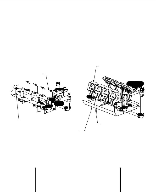
The GF14 and GF40 Series fryers contain a welded steel (stainless or cold-rolled) frypot that is directly heated by gas flames that are diffused evenly over its lower surface by deflectors. In GF14s, each deflector is made of a single piece of stainless steel; in GF40s, the deflectors are comprised of a ceramic target attached to a stainless steel bracket. The rear deflector on both fryers consists of a box-like mount that is attached to the flue assembly on the back of the fryer. As with the deflectors on the burner assembly, the rear deflector on GF40 fryers has a ceramic target.
GF40 Fryers have ceramic "targets" attached to stainless steel brackets.
GF14 Fryers have stainless steel deflectors without ceramics.
GF14 Fryers have a single orifice for each deflector.
GF40 Fryers have a heat shield assembly below the burner assembly. The heat shield is not present on GF14 fryers.
GF40 Fryers have two orifices for each bracket and target assembly.
The flames originate from orifices in a U-shaped burner manifold positioned beneath the frypot. The orifice diameters differ for natural and Propane (LP) gas and for fryers as indicated in the accompanying table (NOTE: This table shows only the orifices used in elevations up to 1999 feet/609 meters. See Chapter 2 (GF14) or Chapter 3 (GF40) for orifices required at other elevations). GF14 fryers have one orifice per deflector; GF40 fryers have two orifices per deflector assembly.
GF14/GF40 Series Orifice Sizes (0-1999 ft/609 m)
Fryer & Gas Type |
Inches |
Millimeters |
GF14 Natural |
0.065 |
1.65mm |
GF14 Propane (LP) |
0.041 |
1.05mm |
GF40 Natural |
0.057 |
1.45mm |
GF40 Propane (LP) |
0.034 |
0.86mm |
1-1
An electromechanical millivolt gas valve regulates gas flow to the burner manifold. GF14/GF40 fryers use a pilot ignition system to control burner firing.
Pilot Ignition System
The pilot ignition system is made up of the pilot orifice, pilot hood, and a thermopile. The pilot serves two purposes: lighting the burner and heating the thermopile. In operation, the thermopile is in contact with the pilot flame and generates millivolts. The millivolt output passes through a normally closed high-limit switch and energizes the gas valve pilot coil, which in turn opens the pilot valve. If the pilot flame is extinguished, voltage is lost to the gas valve pilot coil and the pilot valve closes.
Thermostats
These fryers are equipped with adjustable operating thermostats. The temperature at which the thermostat opens and closes is adjusted by physically changing the setting of the thermostat itself by means of an attached knob. The thermostat used in the GF14/GF40 Series fryers is sensitive to one-degree changes in temperature.
Fryers in the GF14/GF40 series are also equipped with a high-limit thermostat. In the event that the fryer fails to properly control the oil temperature, the high-limit thermostat prevents the fryer from overheating to the flash point. The high-limit thermostat acts as a normally closed power switch that opens when exposed to temperatures above 425ºF to 450ºF (218ºC to 232ºC).
1.2Accessing Fryers for Servicing
 DANGER
Moving a fryer filled with cooking oil/shortening may cause spilling or splattering of the hot liquid. Follow the draining instructions in Chapter 3 of the Installation and Operation manual before attempting to relocate a fryer for servicing.
1.Drain all cooking oil/shortening from the fryer.
2.Shut off the gas supply to the unit and disconnect the unit from the gas supply.
3.Remove any attached restraining devices.
4.Relocate the fryer for service accessibility.
5.After servicing is complete, reconnect the unit to the gas supply and reattach the restraining devices.
6.Refill the frypot with cooking oil/shortening.
1.3Cleaning the Gas Valve Vent Tube
Refer to Quarterly Checks and Services in Chapter 4 of the Installation and Operation manual.
1-2
1.4Calibrating the Operating Thermostat
Refer to Quarterly Checks and Services in Chapter 4 of the Installation and Operation manual.
1.5Checking the Burner Manifold Pressure
Refer to Semi-Annual Checks and Services in Chapter 4 of the Installation and Operation manual.
1.6Adjusting Deflector Spacing and Alignment
 DANGER
Drain the frypot or remove the handle from the drain valve before proceeding further.
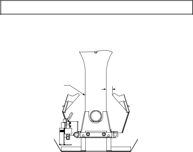
Proper spacing of the edge of the deflectors is ¾-inch (19mm) from the frypot side. To adjust target spacing, bend the brackets to which they are attached away or toward the frypot to the proper distance. (A length of board of the proper thickness is useful as a gauge to verify spacing and alignment.) The illustration below depicts a typical GF40. The GF14 procedure is the same except that there are no ceramic targets.
Gas valve and associated components ommitted for clarity.
Frypot Side
Deflector 
Edge
Adjust deflectors to attain a 3 / 4 - i n c h ( 1 9 m m ) spacing between the edge of the deflector and the frypot side.
.75-inch (19mm)
1.7Adjusting the Pilot Flame
1.Remove the cap shown in the illustration below to access the pilot flame adjustment screw in the gas valve.
1-3
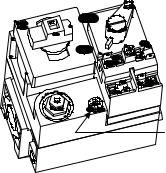
Remove this cap to access the pilot flame adjustment screw.
2.Using a small, flat-tipped screwdriver, turn the pilot flame adjustment screw counterclockwise to increase the length of the flame or clockwise to decrease the length of the flame. Adjust the flame to a length of 1 to 1½ inches (25 to 38 mm).
3.Reinstall the pilot flame adjustment screw cap.
1.8Replacing Fryer Components
1.8.1 Replacing the Operating Thermostat
1.Drain the fryer and turn the gas off.
2.Remove the thermostat knob by pulling straight out on the knob with a firm, steady pull.
3.Disconnect the wires from the thermostat.
4.Remove the two mounting screws to release the thermostat control from its mounting bracket.
5.Straighten the clips that secure the thermostat bulb to the frypot. Use a slotted socket to unscrew the thermostat from the frypot.
6.Loosen the capillary tube compression nut (the small nut) on the replacement thermostat so that it slides freely on the capillary tube. Apply a small amount of Loctite™ PST56765 compound or equivalent to the threads of the large fitting and screw the replacement thermostat securely into the frypot, being careful not to twist the capillary tube as the fitting is tightened. DO NOT tighten the capillary tube compression nut at this time.
1-4
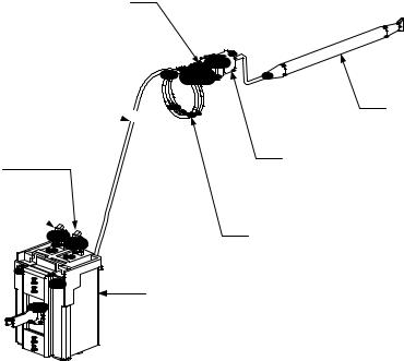
Compression Nut
Capillary Tube 

Attach wire 2C to this terminal.
Attach wire 1C to this terminal. 
Thermostat Bulb
Large fitting screws into frypot.
Carefully coil excess capillary tube after securing thermostat bulb to frypot and tightening compression nut.
Thermostat Control
7.Position the thermostat bulb in the retaining clips and fold the clips down to secure it in place.
8.Gently form the capillary tube so that it lies close to the bottom surface and front wall of the frypot, working any slack out through the fitting (see illustration above).
9.Tighten the capillary tube compression fitting and carefully coil the excess capillary tubing as shown in the illustration on Page 1-4. Mount the thermostat control to the mounting bracket using the screws removed in Step 4.
10.Connect the wires disconnected in Step 3 above to the thermostat as shown in the illustration on Page 1-4.
11.Install the thermostat knob on the shaft of the thermostat control. Calibrate the thermostat in accordance with the procedures contained in the Quarterly Checks and Services section of Chapter 4 of the Installation and Operation manual.
1.8.2 Replacing the High-Limit Thermostat
1.Drain the fryer and turn the gas off.
2.Disconnect the high-limit wires from the gas valve terminal block.
3.Use a slotted socket to unscrew the thermostat from the frypot.
4.Apply a small amount of Loctite™ PST56765 compound or equivalent to the threads of the new highlimit and screw it securely into the frypot.
5.Connect the wires to the gas valve terminals as shown in the illustration below (polarity does not matter).
1-5
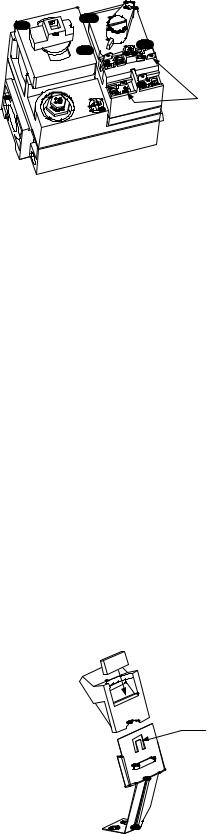
Attach hi-limit wires to these terminals.
Polarity does not matter.
1.8.3 Replacing Deflectors
1.Drain the fryer and disconnect it from the gas supply.
2.Disconnect the wires from the gas valve terminal block, marking each wire to facilitate reconnection.
3.Disconnect the pipe union collar at the right side of the gas valve.
4.On GF40 fryers, remove the burner heat shield hanger screws at the front of the burner and remove the heat shield.
5.Remove the burner hanger screws and lower the front of the burner assembly. Pull it forward to clear the rear burner hanger, then lower the burner to the floor of the cabinet. Carefully pull the burner assembly from the cabinet.
6.GF14: Use a ½-inch box end wrench to remove the brass orifice that holds the deflector to the burner manifold. Position the new deflector and reinstall the orifice.
GF40: To replace only the ceramic targets, straighten the target locking tab with a pair of needle nose pliers or a screwdriver and slide the target up and off the bracket. Recover the insulation from the old target and install with the replacement ceramic. Slide the replacement target onto the bracket, then position the insulation in the opening between the bracket and the ceramic. Bend the locking tab down to secure ceramic in place (see illustration below).
|
Bend this tab up |
|
to release |
|
ceramic and |
|
insulation. When |
|
new ceramic and |
Slide ceramic down |
insulation have |
been positioned |
|
into slots of the |
in bracket, bend |
bracket, then position |
the tab down to |
insulation into opening |
secure them in |
atop the ceramic. |
place. |
To replace the entire target assembly, use a ½-inch box end wrench to remove the brass orifices that hold the assembly to the burner manifold. Position the new assembly and reinstall the orifices.
1-6
 Loading...