


ER Generation II |
REFERENCE MANUAL |
FRY |
ECHNICALT |
OVL |
|
™ |
|
FEB 2010
Edition
Introducing the LOV™ Fryer |
1 |
|
The LOV™ Systems |
2 |
|
M3000 |
12 |
|
RTI-equipped Systems |
31 |
|
Board Replacement |
38 |
|
Wiring Diagrams |
41 |
|
Pin Positions |
44 |
|
|
|
|
Frymaster and Dean Technical Service |
||
8700 Line Ave, Shreveport, LA 71106 |
|
|
Service Hotline: 800-551-8633 |
*8196506* |
|
Website: www.frymaster.com |
||
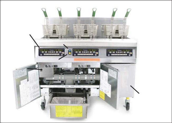
LOV™ Generation II Technical Reference
M3000 Computer
Filter Light
Replace JIB Light
Diagnostic
LED Screen
JIB
(behind right door)
The LOV™ fryer.
Introducing the Low Oil Volume Fryer
The Low Oil Volume (LOV™) fryer is a McDonald’s-only, feature-laden version of the electric RE fryer or gas H55 fryer. The enhancements found on the LOV™ fryer include:
•Low volume frypot — 30 pounds (15 liters) rather than 50 pounds (25 liters) of oil.
•Automatic top-off — the fryer automatically maintains an optimal oil level with a reservoir in the cabinet.
•M3000 computer — a sophisticated controller with multiple levels of programming.
•Automatic filtration — the fryer performs hands-free filtering at prescribed cook cycle counts or at prescribed times.
•Oil savings — The combination of a low-volume fry vat and oil automatically kept at a optimal level, reducing oil usage.
1
LOV™ Generation II Technical Reference
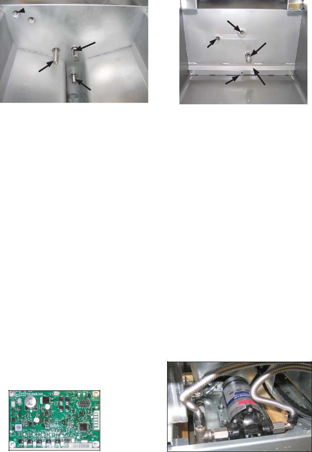
 ATO Sensor
 AIF Sensor
|
Temperature |
|
RTD |
Oil Return |
|
Sensor |
High limit |
|
Ports and sensors inside a gas frypot. Oil return/ top off is at bottom rear of cool zone.
ATO Sensor
High limit
AIF Sensor
Oil Return/Top |
Oil Deflector |
|
Off Slots |
||
|
Ports and sensors inside an electric frypot.
The LOV™ Systems
Auto Top Off
The core of the system is the automatic top-off board, which senses when the oil level is low and fills the pot to the top line.
The oil level is monitored by an RTD (Resistance Temperature Detector) sensor in the frypot at the upper oil level. The oil is moved to the pot from a reservoir, called a JIB (Jug In Box), to the frypot with a pump.
A circuit board, the ATO (Automatic Top Off), is located inside a box behind the JIB. It monitors the oil-level RTD and activates the pump when it senses an oil temperature drop of 60°F (33°C) below setpoint, indicating the oil has moved away from the sensor. The ATO sends a signal to the MIB (Manual Interface Board), which then sends a signal to the AIF to open the actuator on the return valve of the frypot to be topped off.
Once the actuator has opened the return valve, oil is pumped into the vat for a specified amount of time (approximately 60 seconds). When the ATO RTD detects a temperature within 55°F (30°C) of setpoint, it is satisfied and the actuator closes the valve.
Top off will continue on the next vat if needed. The system is not suited to filling the frypot when it is empty and there are safeguards to prevent it from activating when the fryer is cold and the oil is resting at the lower position.
The system is not active until the oil in the frypot reaches setpoint. That temperature is monitored by the temperature probe. The activation of the system is handled by the fryer’s computer, the M3000. The automatic top off system is also inactive during filter dispose cycles.
The system works the same in McDonald’s gas and electric LOV™ systems.
The level of the reservoir, or JIB, is monitored by the ATO and the M3000 computer. If a low oil condition is not rectified with two top off attempts or within 6 minutes, the low JIB light is illuminated on the front of the fryer. It will stay illuminated until the JIB is replaced and the orange button has been pressed and held to reset the light (see page 34).
The ATO board positioned underneath the LON gateway controls the top off of the fry pots.
The pump that moves oil from the reservoir to the frypots is visible above.
2
LOV™ Generation II Technical Reference
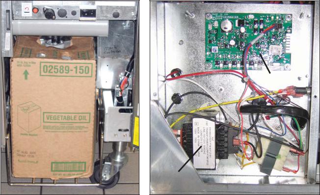
ATO Board
Transformer
The reservoir, or JIB, rests behind the right door of the fryer. A light on the front of the fryer illuminates when the jug is empty.
The ATO board is positioned under the LON gateway in a box with a transformer that provides power to the board. The LON gateway must be removed to access the ATO board.
Troubleshooting the Top Off System
Problem |
Probable Causes |
Corrective Action |
|
|
|
|
|
Frypot tops off cold. |
Incorrect setpoint. |
Ensure setpoint is correct. |
|
|
|
|
|
|
|
A. Check to ensure J5 on front of |
|
|
A. J5 connection unplugged. |
ATO board is fully locked into |
|
|
connector. |
||
|
|
||
No power to ATO board. |
B. Fuse blown. |
B. Ensure fuse below right control |
|
box is not blown. |
|||
|
|
||
|
C. Transformer malfunction. |
C. Check that proper voltage is |
|
|
present at transformer. See |
||
|
|
||
|
|
charts on pages 43-47. |
|
|
|
|
|
|
A. Loose wire connection. |
A. Ensure the yellow LED is |
|
|
securely attached to plug J6 on |
||
|
|
||
|
B. Power in the component box is not |
the ATO board. |
|
The yellow JIB low light |
B. Ensure power is present in the |
||
won’t illuminate. |
present. |
component box. |
|
|
|||
|
C. Failed transformer. |
C. If power is present in component |
|
|
box, check the transformer for |
||
|
|
||
|
|
correct voltage. |
3
LOV™ Generation II Technical Reference
Problem |
Probable Causes |
Corrective Action |
|
|
|
|
|
|
|
A. Check to see that fryer is heating. |
|
|
|
Fryer temperature must be at |
|
|
|
setpoint. Check ATO probe |
|
|
|
resistance. If probe is bad, replace |
|
|
|
the probe. |
|
|
|
B. Ensure that the oil in the JIB is |
|
|
|
above 70°F (21°C). |
|
|
|
C. With the computer OFF, press |
|
|
A. Probe temperature lower than |
TEMP button and ensure the |
|
|
ATO version appears. If not, |
||
|
setpoint. |
||
|
the connection between the AIF |
||
|
|
||
|
B. Oil is too cold. |
and the ATO board may be bad. |
|
|
Ensure the 6-pin CAN connectors |
||
|
|
||
|
C. Bad Connection. |
are tight between AIF (J4 and J5) |
|
|
and ATO (J10) boards. |
||
|
|
||
Frypots won’t top off. |
D. ATO board power loss. |
D. Power to the ATO board has been |
|
cut off. Restore power to the board |
|||
|
|
||
|
E. Failed transformer/harness. |
and clear any service required |
|
|
errors. |
||
|
|
||
|
F. ATO pump failed. |
E. Ensure transformer in ATO box is |
|
|
functioning properly. Check power |
||
|
|
||
|
G. Failed ATO board. |
from transformer to ATO board. |
|
|
Ensure all harnesses are plugged |
||
|
|
||
|
|
securely into place. |
|
|
|
F. Ensure pump is operational. |
|
|
|
Check voltage to pump. Replace |
|
|
|
the pump if defective. |
|
|
|
G. Check for proper voltages using the |
|
|
|
pin position charts found on pages |
|
|
|
43-47. If ATO found defective, |
|
|
|
replace ATO board and clear any |
|
|
|
errors. |
|
|
|
A. Ensure all wiring harnesses are |
|
One vat tops off but other |
A. Loose wire connection. |
securely connected to ATO board |
|
|
and solenoids. |
||
vats fail to top off. |
|
||
B. Actuator issue. |
B. Check return actuator to ensure |
||
|
|||
|
|
actuator is functional. |
|
|
|
|
|
Incorrect vat tops off. |
A. Wired incorrectly. |
A. Check wiring. |
|
|
|||
B. Flexlines connected to wrong vat. |
B. Switch flexlines to correct vat. |
||
|
|||
|
|
||
|
|
|
|
|
|
A. Clear filter error properly. When |
|
|
|
change filter pad YES/ |
|
|
A. Filter error exists. |
NO is displayed, do NOT press |
|
|
any button until the pan has been |
||
One vat doesn’t top off. |
B. Actuator, pump, loose connection, |
removed for at least thirty seconds. |
|
After thirty seconds have elapsed, |
|||
|
|||
|
RTD or ATO issue. |
the computer returns to OFF or last |
|
|
|
display. |
|
|
|
B. Check actuator, ATO pump, wire |
|
|
|
connections, RTD and ATO board. |
|
|
|
|
4

LOV™ Generation II Technical Reference
Auto Filtration (MIB and AIF)
The auto filtration system is controlled by the M3000 computer, the AIF (Automatic Intermittent Filtration) board and the MIB (Manual Interface Board). The filtration is made hands-off by actuators operating the drain and return valves.
The computer is programmable, and it allows filter cycles to be launched after a set number of cook cycles and a prescribed elapsed time.
The system can be set to lock out automatic filtration during busy times, such as the lunch rush.
An AIF board is mounted under each fry vat.
The fryer prompts for filtration by illuminating a blue LED on the front and a text prompt on the computer. The operator can say no; cooking can continue.
Responding “yes” leads to communication between the MIB and the AIF boards. The MIB controls and oversees the filtration; the AIF board operates the actuators, which open and close the valves.
The MIB is in the fryer cabinet. It is partially covered by a sheet metal cover and the LED display is visible. Buttons behind the cover allow limited manual operation of the system and its valves. The cover should be reinstalled after service.
The LED displays codes that can be used to diagnose failures (see chart on page 45).
(1) Responding to the Blue LED filter prompt with “yes” starts a filter cycle that lasts about as long as a cook cycle (approx. 4 minutes). Communication between the M3000 computer, the manual interface (MIB board), and the automatic intermittent filtration (AIF board) handle the process.
(2) Actuators open and close the drain valve and return valve, (3) emptying and refilling the frypot.
1 |
|
2 |
|
3 |
5
LOV™ Generation II Technical Reference
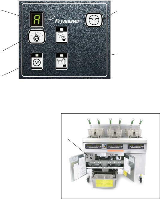
Mode Display
Shows status
(auto or manual) vat number (when operating valves manuals) and displays error codes.
Vat Selection
Selects vat for manual operation of valves.
Manual/Auto
Switches fryer from auto to manual operation.
The MIB board.
Reset
Resets system, ensures all valves are closed.
Drain
Opens and closes  drain valves in manual mode.
Return
Opens and closes return valves and turns on filter pump in manual mode.
Manual — Used to toggle between automatic and manual filtration mode. The unit must be in manual mode for the other MIB buttons to operate.
Select — Used to scroll through the vats, which are shown numerically in the LED.
Drain — Used to open and close the drain valve of the vat indicated on the display. When pressed an LED on the button indicates activity: slow blink, awaiting response from AIF; LED illuminated constantly, drain open; no illumination, drain closed.
Return — Used to open and close the return valve on the vat indicated on the display. It also controls the pump. When pressed an LED on the button indicates activity:
•blink: awaiting response from AIF,
•LED illuminated constantly: drain open,
•no illumination: drain closed.
The MIB is mounted behind the left door. See arrow.
The pump operates with a momentary switch. Pressing and holding the return button after the valve is open activates the filter pump. Releasing the button deactivates the pump.
The mode display on the face of the MIB board displays a range of letters, which indicate activity or an error. These codes are listed on the next page.
6
LOV™ Generation II Technical Reference
Error Codes
1L, 1r - 5L, 5r — Numbers correspond to vats: “L” indicates the left side of a split vat. “r” indicates a full vat or the right side of a split vat.
A — Auto mode: auto filtration enabled.
E — Drain or return valve not in desired state: display alternates between E and vat number. (Ensure actuator is plugged in and in the home position.)
n — Network Error: An “n” displays for 10 seconds if no communication is received from the cooking computer within ten seconds after a power on.
P — Pan switch: filter pan is not in place or not sensed. Auto Filtration disabled.
r — Reset: r alternating with a vat number indicates that the MIB board is resetting. If r is displayed without alternating with a vat number, a problem may exist with the MIB board itself.
Three horizontal lines — temperature sensor: sensor did not detect that the vat was full during auto filtration.
Manual Draining, Filling, Filtering with MIB
1 |
2 |
3 |
1.Press the M button, which switches the board to manual. The display becomes the number of the vat to be controlled manually.
2.Press the vat selector button until the desired vat number is displayed.
3.Press the drain button to drain the oil or the press and hold the return button to return oil to the vat displayed. Opening the drain and pressing and holding the return button after valve is open allows filtration.
4.Pressing the M button again returns the board to automatic mode.
7
LOV™ Generation II Technical Reference
Troubleshooting the Manual Interface Board (MIB)
Problem |
Probable Cause |
Corrective Action |
|
|
1. Filter pan out of position. |
1. Ensure filter pan is fully inserted into fryer. |
|
|
2. Oil Level is too low. |
||
|
2. Ensure oil level is above the oil level sen- |
||
|
3. Ensure MIB board is not in |
||
|
sor. |
||
|
manual mode. |
||
|
3. Ensure MIB board is in “A” automatic |
||
Auto filtration |
4. Ensure MIB cover is not |
||
mode. |
|||
won’t start. |
damaged and pressing |
||
4. Remove and replace cover and see if filtra- |
|||
|
against buttons. |
||
|
tion will start. |
||
|
5. Filter relay has failed. |
||
|
5. Replace filter relay with part number 807- |
||
|
6. AIF disable is set to YES, |
||
|
4482 24VDC relay. |
||
|
blue light doesn’t light. |
||
|
6. Set AIF disable in Level 1 to NO. |
||
|
7. Filter motor thermal switch |
||
|
7. Press filter motor thermal switch. |
||
|
is tripped. |
||
|
8. Ensure AIF clock is set to disabled. |
||
|
8. AIF clock enabled. |
||
|
|
||
MIB display shows |
An error has occurred and |
See MIB display diagnostics on page 46 for |
|
something other |
|||
displayed character indicates |
explanation. |
||
than an “A” or vat |
|||
error. |
|
||
number. |
|
||
|
|
||
|
|
|
|
No power present |
Transformer has failed in left |
Check output on the left transformer in left |
|
component box; should read 24VAC. If not |
|||
at the MIB board |
component box. |
||
replace transformer. |
|||
|
|
||
|
|
|
|
|
|
Press and hold reset button in top right cor- |
|
|
|
ner for five seconds. The drain, return and |
|
MIB will not clear |
Error remains in non-volatile |
manual/auto LEDS will illuminate and the MIB |
|
error. |
memory. |
will reset and clear any remaining errors from |
|
|
|
memory. Allow 60 seconds to reset. If an error |
|
|
|
still exists, then another issue exists. |
|
|
|
|
|
|
|
Ensure the CAN bus system is terminated at |
|
|
|
BOTH ENDS (on the M3000 connector J6 and |
|
|
|
on the ATO board connector J9) with a resistor |
|
|
|
equipped 6-pin connector. |
|
|
|
• Unplug and reseat all wiring harnesses in |
|
|
|
CAN system. Resistance between pins |
|
|
|
2 and 3 on the CAN network connectors |
|
MIB indicates in- |
|
should be 120 ohms. |
|
|
• Check software version numbers on all |
||
correct number of |
|
||
|
M3000 computers and ensure all display |
||
vats. |
|
||
|
an AIF version. If an AIF version is miss- |
||
|
|
||
|
|
ing, the AIF board may be missing power. |
|
|
|
Check pins 5 and on J4 and J5 of the af- |
|
|
|
fected AIF board for proper voltage. |
|
|
|
• The locator pin in J2 of the AIF board is |
|
|
|
either loose or in the incorrect position. |
|
|
|
See the chart on pages 47 of this manual |
|
|
|
for proper pin position. |
|
|
|
|
8
LOV™ Generation II Technical Reference
Problem |
Probable Cause |
Corrective Action |
|
|
|
A. Ensure the CAN bus system is terminated |
|
|
|
at BOTH ENDS (on the M3000 connector |
|
|
|
J6 and on the ATO board connector J10) |
|
|
|
with a resistor equipped 6-pin connector. |
|
|
|
B. With the computer OFF, press TEMP but- |
|
|
|
ton and ensure the AIF version appears. |
|
|
|
If not, the 24V to the AIF boards may be |
|
|
|
missing. Ensure all 6-pin CAN connectors |
|
|
|
are tight between the M3000 (J6 and J7), |
|
|
|
MIB (J1 and J2), AIF (J4 and J5) and ATO |
|
|
|
(J10) boards. |
|
|
|
C.With the computer OFF, press TEMP but- |
|
|
|
ton and ensure the ATO version appears. If |
|
|
|
not, check the CAN wire harness between |
|
|
|
the AIF board J4 or J5 and the ATO board |
|
|
|
J9 or J10. The ATO fuse on the right side |
|
|
|
of the ATO box may be loose or blown; |
|
|
|
the 110V to the ATO transformer may be |
|
|
|
missing or bad. The J4/J5 connector may |
|
|
|
be loose. |
|
|
|
D.Check to see if MIB has 24V on pins 5 and |
|
MIB board alternat- |
Network error on the CAN bus |
6 of J2. Check to see if 24V is present on |
|
ing “E” and “vat |
communication. |
pins 5 and 6 of wire harness plugging into |
|
number and side.” |
J4 or J5 of the first AIF board. If 24V miss- |
||
|
|||
|
|
ing, check the pins. Replace the harness if |
|
|
|
necessary. |
|
|
|
E. Check continuity between each color wire |
|
|
|
on the CAN connectors into J7 on the far |
|
|
|
right computer and J10 on back of the ATO |
|
|
|
board (black to black, white to white, and |
|
|
|
red to red) and ensure there is no continu- |
|
|
|
ity between different color wires (black to |
|
|
|
red, red to white, and white to black). |
|
|
|
F. Ensure black computer locator wires are |
|
|
|
connected from ground to correct pin posi- |
|
|
|
tion (see pages 43-47). |
|
|
|
G.Ensure all boards have the corner ground |
|
|
|
wire attached and tightened. |
|
|
|
H.Check for loose locator pin or incorrect |
|
|
|
positioning in J2 of the AIF board. See the |
|
|
|
charts on pages 43-47 of this manual for |
|
|
|
proper pin position. |
|
|
|
I. Bad MIB and/or AIF board. |
|
|
|
J. Broken resistor lead. Unwrap the resistor |
|
|
|
leads and check ends. |
9
LOV™ Generation II Technical Reference
Troubleshooting the AIF System (AIF)
Problem |
Probable Cause |
Fix |
|
|
|
1. Ensure the actuator is plugged into the correct |
|
|
1. Actuator is plugged into wrong |
connection (J1 for FV return, J3 for DV return; |
|
Wrong vat |
J6 for FV drain, J7 for DV drain). |
||
connector. |
|||
opens. |
2. Ensure the locator pin is in the proper position |
||
2. Locator pin is in wrong position. |
|||
|
in plug J2. (See charts on pages 43-47 of this |
||
|
|
||
|
|
manual for proper pin position.) |
|
|
|
|
|
|
|
1. Check pins 5 and 6 of J2 at the MIB board. |
|
|
|
Should read 24VDC. Check voltage on pins |
|
|
|
5 and 6 at the other end of the harness and |
|
|
|
ensure 24VDC is present. Check pins 5 and 6 |
|
|
|
for 24VDC on plugs J4 and J5 on AIF boards. |
|
|
|
2. Ensure actuator leads are plugged into AIF |
|
|
|
board (J1 for FV return, J3 for DV return; J6 |
|
|
|
for FV drain, J7 for DV drain). |
|
|
|
3. Check the power on the connector of the |
|
|
|
problem actuator while manually opening |
|
|
1. No power to AIF board. |
or closing the actuator. Pins 1 (black) and 4 |
|
|
2. Actuator unplugged. |
(white) should produce +24VDC when the |
|
Actuator doesn’t |
3. AIF board failure. |
actuator is opening; -24VDC should be read |
|
function. |
4. Actuator readings are out of |
from Pins 2 (red) and 4 (white) when the |
|
|
tolerance. |
actuator is closing. If either voltage is missing, |
|
|
5. Actuator is bad. |
the AIF board is likely bad. Test the actuator |
|
|
|
by plugging into another connector to open |
|
|
|
or close. If the actuator operates, replace the |
|
|
|
board. |
|
|
|
4. Check resistance of the potentiometer |
|
|
|
between pin 2 (purple wire) and pin 4 (gray/ |
|
|
|
white wire). Closed should read 0-560Ω. Open |
|
|
|
should read 3.8KΩ - 6.6KΩ. |
|
|
|
5. If proper voltages are seen at the connector |
|
|
|
and the actuator doesn’t operate, replace the |
|
|
|
actuator. |
Oil Return Sensor Troubleshooting (Gas LOV™ Fryers)
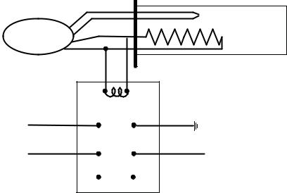
The oil return sensor is a device that is used to prevent dry firing of the burners. The sensor looks similar to a high limit. The sensors are energized when the computer is powered on with a soft on. The sensor heats up and detects the oil around it. During filtration when the oil is drained, it senses the difference between the oil and air. It is controlled with a board located next to the interface board (right) and a separate egg shaped plastic device (far right) that contains additional electronics. Use care when working with the sensor as temperatures may reach as high as 500°F (260°C).
The oil return sensor is controlled by a small green board and the electronics inside the plastic, egg-shaped device shown above to prevent dry firing.
10
LOV™ Generation II Technical Reference
If oil is surrounding the heater, the oil will prevent the heater from ever reaching its setpoint. Once oil is removed during filtration, the heater reaches setpoint and cycles a thermostat every four seconds. Since the cycle is only four seconds long, the seven second delay is not made and the gas valve won’t open.
The 120VAC is on T2 in the control box traveling in on pin 11 of J3 and out pin 7 on J1 (DV) or pin 7 on J3 (FV).
Typical sensor-related failures:
•Low temp but no call for heat (heat light),
•Stuck in melt cycle with no call for heat,
•Filter error (IS VAT FULL?) with oil in the filter pan (no oil in the vat).
If the computer doesn’t exit melt cycle or continues to display low temp and does not heat, ensure that the gas supply, gas valve, and other components are working properly. If no heat lamp illuminates because no call for heat is initiated, check the following (see diagram below):
•Power to oil sensor (from previous basket lift relay on interface board K1(DV) or K4 (FV)). Check pin 7 on J1 (DV) or pin 7 on J3 (FV) for 120VAC.
•Power to heater/relay coil on relay board. Check voltage to the coil on pins 8 and 1 to ensure that 120VAC is present with oil in the vat. If the vat is empty, the power will cycle 4 seconds on, 4 seconds off.
•Check between pin 3 and 2; 5VDC for air and 0VDC for oil. A common message for a shorted harness or issue is IS DRAIN CLEAR? with oil in the filter pan.
•Check ground on pin 2 on relay board to stud for a secure ground.
•Check AIF communication harness. Interrupted communication will prevent the fryer from heating.
•If the oil level sensor is cycling 4 sec. on/off and oil is surrounding the sensor, the sensor may have a carbon build up that is self insulating the sensor. Use a no scratch pad to remove carbon build up.
|
Black |
|
(To J1 Pin 7 (DV) |
|
|
or J3 Pin 7 (FV)) |
Fixed Setpoint |
|
|
120V |
|
|
Temp. Control |
|
|
|
|
White
(To T2 Terminal Block
Line Voltage In From
Oil Level Sensor (Basket Lift) Relay on Interface Board
24VAC from Interface Board through High Limit (Ign. Module Call for Heat)
To (optional Drain
Switch) and Gas
Valve
 Thermocouple
Heater
120V  (350 ohms US)
(1325 ohms Intl)
120V (US) 230V (Intl) 40W Heater w/ Thermocouple
Black 8 |
|
1 White |
|
Black 7 |
C |
2 Green |
|
Black 6 |
NO |
3 Red |
To AIF Board J2 Pin 9 DV |
|
|
|
or 10 FV (AIF Oil Signal) |
5 |
NC |
4 |
|
Time Delay Relay Board DPDT 7sec. Delay on Make
11
LOV™ Generation II Technical Reference
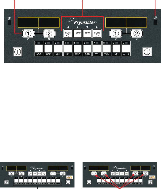
M3000 Computer |
|
|
Overview |
|
|
Cook Cycle and |
Filter, Temp, Info, Programming |
Heat Indicator |
Selection Buttons |
and Navigation Buttons |
Lamp |
|
LED Display |
LED Display |
|
|
|
|
|
|
|
|
|
|
|
|
|
|
|
|
|
|
|
|
|
|
|
|
|
|
|
|
|
|
|
|
|
|
|
|
|
|
|
|
|
|
|
|
|
|
|
|
|
|
|
|
|
|
|
|
ON/OFF |
|
Product Buttons |
ON/OFF |
||||
The M3000 computer retains the one-button ease of the M2000 and M100B, combining it with the utility of 40-product menu capability. It will operate with electric and gas fryers, both fulland splitvat.
On single product vats, press any of the cook cycle buttons to begin cooking. On multi-product vats, press a product button, and then a cook cycle button under the display showing the desired product name.
For example, a typical M3000 computer on a 3-vat fry station will display FR FRIES. Pressing one of the cook cycle buttons will begin a cook cycle for French fries.
The chicken/fillet station will usually display dashed lines [----]. Pressing the product button assigned to McChicken, for example, will cause mcchick to be displayed. Then, press a cook cycle button beneath the word mcchick to start a cook cycle for McChicken.
---- ---- ---- ---- |
MCC HICK |
MCC HICK |
Product Buttons |
Cook Cycle Buttons |
12
LOV™ Generation II Technical Reference
Navigation
The M3000 uses |
and |
buttons to navigate the various menus and submenus. |
When programming, the left screen shows the menu or submenu item. The right screen is for data entry. Data is entered with alpha-numeric characters, scrolling through lists or by toggling between choices (see diagrams on previous page).
During programming, if a button is not pushed within one minute, the computer returns to operation mode.
Cook Cycle and Selection Buttons
The 9 and 8 buttons are dual-function buttons shared with the number 1 and 2 buttons. They are located directly below the LED displays (see diagrams on previous page). Use these buttons to select or cancel functions. The 8 button is used to back out of and quit submenus.
Filter, Temperature, and Info Buttons
The < FLTR and FLTR > buttons (see diagram) are used to filter the left and right vats of a split vat fryer on demand, while the right FLTR > button is used to filter a full vat on demand. If pressed once, the FLTR buttons will display the number of cook cycles remaining until a filtration prompt. When a FLTR button is pressed twice, the date and time of the last filter will be displayed.
Temp Button
The TEMP button, if pressed once while the fryer is on, displays current vat temperature on both sides. If the TEMP button is pressed twice while the fryer is on, it shows the setpoint temperatures of the vats. If the fryer is off, the display shows the current versions of software.
Info Button
The INFO button, if pressed once when the fryer is on, shows the recovery time for each vat from the last test. Recovery displays the time required for the fryer to raise the temperature of the oil 50°F (28°C) between 250°F (121°C) and 300°F (149°C). Maximum recovery time should not exceed 1:40 for electric or 2:25 for gas.
If recovery time exceeds these times, the computer will display RECOVERY FAULT. The error can be cleared and alarm silenced by pressing the 9 button. The second consecutive time it will display RECOVERY FAULT CALL SERVICE. The error can be silenced and temporarily cleared by pressing the 9 button. However, each time the fryer is started up and the test performed, the error will continue to appear until code 0042 is entered in tech mode (see page 27).
If the INFO button is pressed and held for three seconds it shows information such as usage, filter statistics and last cook cycles.
13
LOV™ Generation II Technical Reference
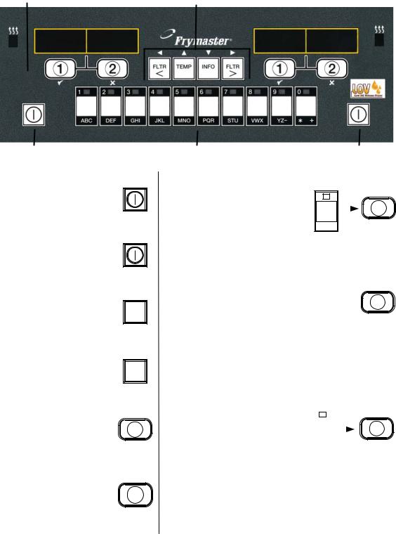
Cook Channel |
Basic Operation |
|||
Filter, Temp, Info, |
||||
and Selection Buttons |
Programming and Navigation Buttons |
|||
|
|
|
|
|
|
|
|
|
|
|
|
|
|
|
ON/OFF
Turn Fryer ON
Press right key for full pot; press key on desired side on a split pot.
Turn Fryer OFF
Press right key for full pot; press key on desired side on a split pot.
Check Frypot Temperature
Press Temp key once.
Displays show frypot TEMP temperatures.
Check Frypot Setpoint
Press Temp key twice.
Displays show frypot TEMP setpoint temperatures.
Cancel Duty or Remove Alarm
Press key under active
display. 2
Start One-Button Cook Cycle (Dedicated Mode)
Press key under
display showing 1 desired item.
Product Buttons |
ON/OFF |
Start Two-Button Cook Cycle (Multi-Product Mode)
Press product key |
|
|
bearing icon for desired |
2 |
|
product. Press cook |
||
|
||
channel button to begin |
|
|
cook cycle. |
|
Change From Dedicated to Multi-Product Mode
Press and hold Cook Channel button under
displayed menu item for 2 approximately 3 seconds
until beep is heard. Display changes to dashed lines.
Change From Multi-Product Mode to Dedicated Mode
Press product key bearing |
|
|
icon for desired product. |
|
2 |
|
||
Press cook channel button |
|
|
under display showing |
|
|
|
|
|
desired item until beep is |
|
|
|
|
|
heard (approx 3 seconds). |
|
|
14
 Loading...