


FilterQuick™ FQGLA-T
Gas Fryer
Service Manual
This manual is updated as new information and models are released. Visit our website for the latest manual.
FOR YOUR SAFETY
Do Not Store or use gasoline or other flammable vapors and liquids in the vicinity of this or any other appliance.
*8197443*
Part Number: FRY_SM_8197443 02/2018

NOTICE
IF, DURING THE WARRANTY PERIOD, THE CUSTOMER USES A PART FOR THIS FRYMASTER EQUIPMENT OTHER THAN AN UNMODIFIED NEW OR RECYCLED PART PURCHASED DIRECTLY FROM FRYMASTER DEAN, OR ANY OF ITS FACTORY AUTHORIZED SERVICERS, AND/OR THE PART BEING USED IS MODIFIED FROM ITS ORIGINAL CONFIGURATION, THIS WARRANTY WILL BE VOID. FURTHER, FRYMASTER DEAN AND ITS AFFILIATES WILL NOT BE LIABLE FOR ANY CLAIMS, DAMAGES OR EXPENSES INCURRED BY THE CUSTOMER WHICH ARISE DIRECTLY OR INDIRECTLY, IN WHOLE OR IN PART, DUE TO THE INSTALLATION OF ANY MODIFIED PART AND/OR PART RECEIVED FROM AN UNAUTHORIZED SERVICER.
NOTICE
This appliance is intended for professional use only and is to be operated by qualified personnel only. A Frymaster Authorized Servicer (FAS) or other qualified professional should perform installation, maintenance, and repairs. Installation, maintenance, or repairs by unqualified personnel may void the manufacturer’s warranty. See Chapter 1 of this manual for definitions of qualified personnel.
NOTICE
This equipment must be installed in accordance with the appropriate national and local codes of the country and/or region in which the appliance is installed. See NATIONAL CODE REQUIREMENTS in Chapter 2 of this manual for specifics.
NOTICE TO U.S. CUSTOMERS
This equipment is to be installed in compliance with the basic plumbing code of the Building Officials and Code Administrators International, Inc. (BOCA) and the Food Service Sanitation Manual of the U.S. Food and Drug Administration.
NOTICE
Drawings and photos used in this manual are intended to illustrate operational, cleaning and technical procedures and may not conform to onsite management operational procedures.
NOTICE TO OWNERS OF UNITS EQUIPPED WITH CONTROLLERS
U.S.
This device complies with Part 15 of the FCC rules. Operation is subject to the following two conditions: 1) This device may not cause harmful interference, and 2) This device must accept any interference received, including interference that may cause undesired operation. While this device is a verified Class A device, it has been shown to meet the Class B limits.
CANADA
This digital apparatus does not exceed the Class A or B limits for radio noise emissions as set out by the ICES-003 standard of the Canadian Department of Communications.
Cet appareil numerique n’emet pas de bruits radioelectriques depassany les limites de classe A et B prescrites dans la norme NMB-003 edictee par le Ministre des Communcations du Canada.
NOTICE
The instructions in this manual for using a bulk oil system for filling and discarding oil are for an RTI system. These instructions may not be applicable to other bulk oil systems.

 WARNING
After installation of a gas fryer and after any maintenance to the gas system of a gas fryer-manifold, valve, burners, etc. – check for gas leaks at all connections. Apply a thick soapy solution to all connections and ensure there are no bubbles. There should be no smell of gas.
 DANGER
Improper installation, adjustment, maintenance or service, and unauthorized alterations or modifications can cause property damage, injury, or death. Read the installation, operating, and service instructions thoroughly before installing or servicing this equipment.
 DANGER
Adequate means must be provided to limit the movement of this appliance without depending upon the gas line connection. All fryers equipped with casters must be stabilized by installing restraining chains. If a flexible gas line is used, an additional restraining cable must be connected at all times when the fryer is in use.
 DANGER
The front ledge of this appliance is not a step! Do not stand on the appliance. Serious injury can result from slips or contact with the hot oil.
 DANGER
Do not store or use gasoline or other flammable liquids or vapors in the vicinity of this or any other appliance.
 DANGER
This product contains chemicals known to the state of California to cause cancer and/or birth defects or other reproductive harm.
Operation, installation, and servicing of this product could expose you to airborne particles of glasswool or ceramic fibers, crystalline silica, and/or carbon monoxide. Inhalation of airborne particles of glasswool or ceramic fibers is known to the State of California to cause cancer. Inhalation of carbon monoxide is known to the State of California to cause birth defects or other reproductive harm.
 WARNING
Use caution and wear appropriate safety equipment to avoid contact with hot oil or surfaces that may cause severe burns or injury.
 DANGER
Keep all items out of drains. Closing actuators may cause damage or injury.

Table of Contents
Section 1: Service Procedures
1.1 |
FQ4000 Menu Summary Trees ......................................................................................................... |
1-1 |
|
|
1.1.1 FQ4000 Menu Tree General Market/Burger King................................................................. |
1-1 |
|
|
1.1.2 FQ4000 Information Statistics Menu Tree General Market/Burger King .......................... |
1-2 |
|
|
1.1.3 FQ4000 Menu Tree Taco Bell................................................................................................... |
1-3 |
|
|
1.1.4 FQ4000 Information Statistics Menu Tree Taco Bell ............................................................ |
1-4 |
|
1.2 |
FQ4000 Password Codes................................................................................................................... |
1-5 |
|
1.3 |
Service Required Errors ..................................................................................................................... |
1-5 |
|
1.4 |
Error Log Codes .................................................................................................................................. |
1-5 |
|
1.5 |
Component Check.............................................................................................................................. |
1-7 |
|
1.6 |
Functional Description....................................................................................................................... |
1-8 |
|
1.7 |
The Electronic Ignition System.......................................................................................................... |
1-8 |
|
1.8 |
Smart Interface Board (SIB)............................................................................................................... |
1-9 |
|
|
1.8.1 |
Full Vat flow through the SIB Board.............................................................................. |
1-10 |
|
1.8.2 |
Split Vat flow through the SIB Board ............................................................................ |
1-11 |
|
1.8.3 |
Frequently Used Test Points for SIB.............................................................................. |
1-12 |
|
1.8.4 |
SIB (Smart Interface Board) Troubleshooting.............................................................. |
1-12 |
|
1.8.5 |
SIB (Smart Interface Board) Pin Positions and Harnesses......................................... |
1-13 |
1.9 |
Thermostats ...................................................................................................................................... |
1-14 |
|
1.10 |
Accessing Fryers for Servicing......................................................................................................... |
1-14 |
|
1.11 |
Cleaning the Gas Valve Vent Tube.................................................................................................. |
1-14 |
|
1.12 |
Checking the Burner Manifold Gas Pressure................................................................................ |
1-15 |
|
1.13 |
Measuring Flame Current................................................................................................................ |
1-17 |
|
1.14 |
Replacing Fryer Components.......................................................................................................... |
1-17 |
|
|
1.14.1 |
Replacing the Controller or the Controller Wiring Harnesses................................... |
1-17 |
|
1.14.2 |
Replacing the SIB ............................................................................................................. |
1-18 |
|
1.14.3 |
Replacing the OIB Relay, OIB Relay Board, Transformer or Blower Relay .............. |
1-18 |
|
1.14.4 |
Replacing the Temp Probe, ATO Probe, VIB Probe, OIB Sensor or High-Limit ....... |
1-18 |
|
1.14.5 |
Replacing an Ignition Module ........................................................................................ |
1-19 |
|
1.14.6 |
Replacing an Ignitor Assembly....................................................................................... |
1-19 |
|
1.14.7 |
Replacing or Cleaning a Combustion Air Blower......................................................... |
1-20 |
|
1.14.8 |
Adjusting the Air/Gas Mixture........................................................................................ |
1-21 |
|
1.14.9 |
Replacing a Gas Valve ..................................................................................................... |
1-22 |
|
1.14.10 |
Replacing a Burner Assembly ........................................................................................ |
1-23 |
|
1.14.11 |
Replacing the Filter Motor or Filter Pump.................................................................... |
1-24 |
|
1.14.12 |
Replacing the Frypot ....................................................................................................... |
1-25 |
|
1.14.13 |
Replacing Frypot Insulation and/or Upper Burner Rails ............................................ |
1-25 |
1.15 Troubleshooting and Problem Isolation ......................................................................................... |
1-28 |
||
|
1.15.1 |
Heating (Ignition) Failure ................................................................................................ |
1-29 |
|
1.15.2 |
Improper Burner Function ............................................................................................. |
1-30 |
|
1.15.3 |
Improper Temperature Control .................................................................................... |
1-31 |
|
1.15.4 |
Controller Malfunctions.................................................................................................. |
1-31 |
|
1.15.5 |
Filtration Malfunctions.................................................................................................... |
1-31 |
|
1.15.6 |
Leakage............................................................................................................................. |
1-32 |
1.16 |
Troubleshooting Guides .................................................................................................................. |
1-32 |
|
|
1.16.1 |
Troubleshooting the 24 VAC Circuit.............................................................................. |
1-33 |
|
1.16.2 Troubleshooting the Gas Valve...................................................................................... |
1-34 |
|
|
1.16.3 Troubleshooting the Temperature Probe.................................................................... |
1-34 |
|
|
1.16.4 Replacing the Reset Switch............................................................................................. |
1-34 |
|
1.17 |
Probe Resistance Chart.................................................................................................................... |
1-35 |
|
1.18 ATO (Automatic Top-Off) and Filtration Service Procedures ...................................................... |
1-35 |
||
|
1.18.1 ATO (Automatic Top-Off Troubleshooting) .................................................................. |
1-35 |
|
|
1.18.2 |
Filtration Troubleshooting.............................................................................................. |
1-38 |
|
1.18.3 Test points on rear of FIB box........................................................................................ |
1-40 |
|
|
|
1.18.3.1 12-pin connector on rear FIB box.............................................................. |
1-40 |
|
|
1.18.3.2 Connections on rear of FIB box ................................................................. |
1-40 |
|
1.18.4 FIB (Filter Interface Board) Filtration Top-off Pin Positions and Harnesses ............ |
1-41 |
|
|
1.18.5 Replacing FIB Board, Power Supply, Filter Relay or Transformer ............................. |
1-42 |
|
|
1.18.6 Replacing the ATO Pump or Solenoid........................................................................... |
1-43 |
|
1.19 FIB (Filter Interface Board) Service Procedures............................................................................ |
1-43 |
||
|
1.19.1 Manually Draining, Refilling, Filtering or Topping off - Manual Filtration Mode .... |
1-43 |
|
|
1.19.2 Control Power Reset Switch........................................................................................... |
1-43 |
|
1.20 Bulk Oil Service Issues ..................................................................................................................... |
1-44 |
||
|
1.20.1 |
Bulk FIB Tests ................................................................................................................... |
1-44 |
|
1.20.2 Bulk Oil Wiring Connection behind Fryer..................................................................... |
1-45 |
|
|
1.20.3 Frymaster FQ-T Fryer and Bulk Oil System Plumbing Schematic ............................. |
1-45 |
|
|
1.20.4 Bulk Test Quick Reference.............................................................................................. |
1-46 |
|
|
|
1.20.4.1 Dispose to Waste, Refill Vat from Bulk...................................................... |
1-46 |
|
|
1.20.4.2 Dispose to Waste ......................................................................................... |
1-46 |
|
|
1.20.4.3 Fill Vat from Bulk.......................................................................................... |
1-47 |
|
|
1.20.4.4 Fill Oil Reservoir from Bulk ......................................................................... |
1-47 |
|
1.20.5 Troubleshooting Oil Reservoir Filling ............................................................................ |
1-47 |
|
1.21 VIB (Valve Interface Board) Service Procedures ........................................................................... |
1-48 |
||
|
1.21.1 VIB (Valve Interface Board) Troubleshooting............................................................... |
1-49 |
|
|
1.21.2 VIB (Valve Interface Board) Pin Positions and Harnesses .......................................... |
1-50 |
|
|
1.21.3 Replacing a VIB (Valve Interface Board) Board............................................................ |
1-51 |
|
|
1.21.4 Replacing a Rotary Actuator........................................................................................... |
1-51 |
|
|
1.21.5 |
Oil Level Sensor ............................................................................................................... |
1-51 |
|
|
1.21.5.1 Oil Level Sensor Troubleshooting.............................................................. |
1-52 |
|
|
1.21.5.2 Oil Level Sensor Diagram............................................................................ |
1-52 |
1.22 FQ4000 Controller Service Procedures.......................................................................................... |
1-53 |
||
|
1.22.1 |
FQ4000 Controller Troubleshooting............................................................................... |
1-53 |
|
|
1.22.1.1 FQ4000 Controller Functional Troubleshooting ...................................... |
1-55 |
1.23 Loading and Updating Software Procedures................................................................................ |
1-58 |
||
1.24 |
Wiring Diagrams ............................................................................................................................... |
1-61 |
|
|
1.24.1 Power Distribution Box Export ...................................................................................... |
1-61 |
|
|
1.24.2 Power Distribution Box Domestic US ........................................................................... |
1-62 |
|
|
1.24.3 FQGLA-T Series LOV™ Simplified Wiring with Color Legend...................................... |
1-63 |
|
|
1.24.4 FQGLA-T Series LOV™ Simplified Wiring with OQS CAN Bridge Board .................... |
1-64 |
|
|
1.24.5 FQGLA-T Series LOV™ Simplified Wiring without OQS CAN Bridge Board .............. |
1-65 |
|
|
1.24.6 Filtration Interface Box (FIB) Wiring .............................................................................. |
1-66 |
|
|
1.24.7 Full Vat Direct Spark Wiring Diagram with Optional OIB Sensor .............................. |
1-67 |
|
|
1.24.8 Dual Vat Direct Spark Wiring Diagram with Optional OIB Sensor ............................ |
1-68 |
|
FQGLA-T SERIES FILTERQUICK GAS FRYERS
CHAPTER 1: SERVICE PROCEDURES
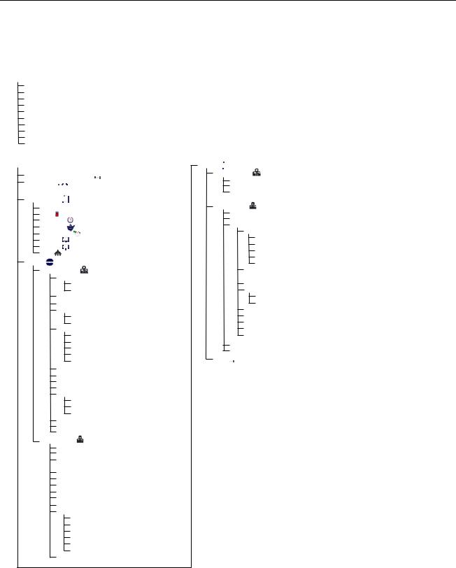
1.1FQ4000 Menu Summary Trees
1.1.1 FQ4000 Menu Tree General Market/Burger King
Reflected below are the major programming sections in the FQ4000 and the order in which the headings will be found in the controller.
Filtration Menu
Quick Filter
Clean and Filter (with OQS)
OQS-Filter
Dispose
Fill Vat from Pan
Fill Vat from Bulk (Bulk Only)
Pan to Waste (Bulk Only)
Drain to Pan
Clean
Polish
Home Button
Crew Mode (Cooking Mode)  Menus (1650)

 Create New Recipes (1650)
Product Name Temp
Cook Time
Sensitivity
Hold Timer Shake 1 Shake 2 Filter
Settings
Manager (1656) Language
Primary
Secondary Date & Time
F° to C°/ C° to F° (Toggles Temperature Scale)
Sound Volume Tone
Filter Attributes
Filter After (Cooks)
Filter Time (Hours) Filter Off Time Filtration Off Settings Clean (Cold/Hot)
Energy Savings (Enabled, Temperature, Time) Lane Assignments (# of Baskets)
Brightness Screen Saver Alarm Attributes
Shake Alarm Mode (Auto / Manual)
Hold Alarm Mode (Auto / Manual) Alarm Timer (Shake Timer / Hold Timer)
Temperature
Oil Dragout
Basket Lift
Service (3000)
Locale (CE / Non-CE) Energy Type (Gas / Electric) Vat Type (Full / Split)
 Basket Configuration
Oil System Type (JIB / Bulk)
Waste Oil (None / Bulk/Front Dispose) Auto Top Off Vat (On / Off)
ATO Delay Time
ATO Type (Auto, Push Button, Both)
Filtration Time Settings OQS Setup
OQS (Enable/Disable)
Oil Type (Oil Curve) Display Type (Number/Text) Discard Now (TPM Value)
Discard Soon (TPM Offset Value) Dispose Delay Timer
Basic Auto Filter (Enable/Disable)
Service
Manager (1656)
E-Log Passcode Setup
USB Menu Operation
 Copy Menu from USB to Fryer
Service (3000)
Manual Filtration
Password Reset Tech Modes
Resets
Factory Menu (Resets Product Recipes) Bad CRC (Resets Alert)
Recovery Fault Call Service (Resets Alert) Reset Factory Resets (Resets to Factory Default) Reset Report Card (Resets Report Card)
Toggle to Select
 F° to C°/ C° to F° (Toggles Temperature Scale)
Filter Pad Time Setup Clear Statistics
Filter Stats Data (Clears Filter Stats) E-Log (Clears E-Log Errors)
Software Upgrade
Vat Tuning (Engineering only) Component Check (9000) Blower
Demo Mode
FIB Reset 1
FIB Reset 2
Crew
 Hi-Limit Test
1-1
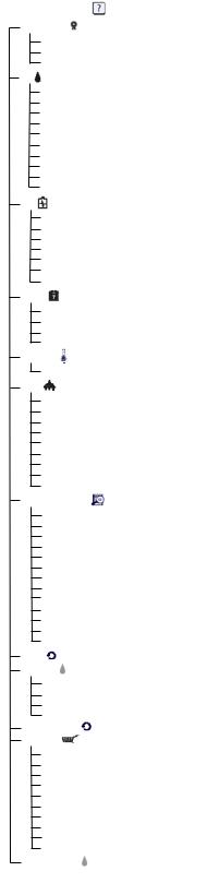
1.1.2 FQ4000 Information Statistics Menu Tree General Market/Burger King
Reflected below are the information statistics in the FQ4000 and the order in which the headings will be found in the controller.
1-2
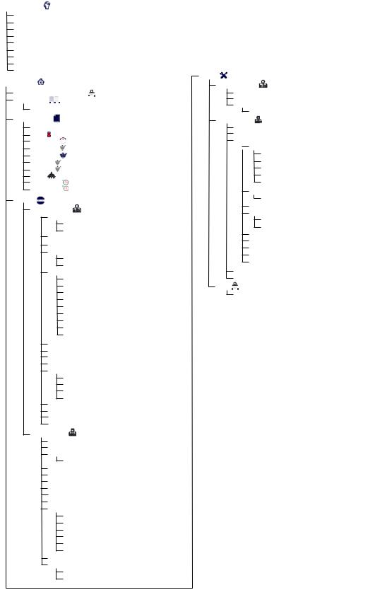
1.1.3 FQ4000 Menu Tree Taco Bell
Reflected below are the major programming sections in the FQ4000 and the order in which the headings will be found in the controller.
1-3
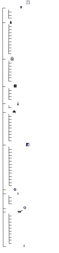
1.1.4 FQ4000 Information Statistics Menu Tree Taco Bell
Reflected below are the information statistics in the FQ4000 and the order in which the headings will be found in the controller.
1-4
1.2 FQ4000 Password Codes
Press the HOME button to enter MENUS, RECIPES, SETTINGS or SERVICE menus.
1650 – MENUS, RECIPES,
1656 – SETTINGS (MANAGER), SERVICE (MANAGER)
3000 – SETTINGS (SERVICE), SERVICE (SERVICE) Enter Tech Mode
9000 – Component Check [SETTINGS (SERVICE), SERVICE (SERVICE) Enter Tech Mode]
The following code is entered when prompted to do so.
1111 – Reset SERVICE REQUIRED Message – Enter when the issue is fixed and prompted to enter code.
1.3Service Required Errors
A SERVICE REQUIRED error with a description of the error displays on the controller. After YES is pressed the alarm is silenced. The controller displays an error message from the list below three times with the location of the error. Then the controller displays SYSTEM ERROR FIXED? YES/NO. If yes is chosen, enter code 1111. If NO is chosen, the system returns to cook mode if possible for 15 minutes, then redisplays error until issue is fixed.
1.4 Error Log Codes
To access the error log, press the home button. Press the service button. Press the manager button. Enter 1656 and press the check button. Press the E-log button. The ten most recent errors are listed from top to bottom, with the top error being the most recent error. A “G” indicates a global error such as a filtration error. Side specific errors in split vats are indicated by L for left or R for right. Pressing the left down arrow allows scrolling through the
errors. If no errors are present the screen will be blank.
Code |
ERROR MESSAGE |
EXPLANATION |
E13 |
TEMPERATURE PROBE FAILURE |
TEMP Probe reading out of range |
E16 |
HIGH LIMIT 1 EXCEEDED |
High limit temperature is past more than 410°F |
|
|
(210°C), or in CE countries, 395°F (202°C) |
E17 |
HIGH LIMIT 2 EXCEEDED |
High limit switch has opened. |
E18 |
HIGH LIMIT PROBLEM |
Vat temperature exceeds 460°F (238°C) and the |
|
DISCONNECT POWER |
high limit has failed to open. Immediately |
|
|
disconnect power to the fryer and call service. |
E19 |
HEATING FAILURE – XXX F or XXX C |
Heating Control latch circuit failed. |
|
|
Heat Contactor failed to latch. |
|
|
|
E25 |
HEATING FAILURE - BLOWER |
The air pressure switch(s) failed to close. |
E27 |
HEATING FAILURE - PRESSURE SWITCH - |
The air pressure switch has failed closed. |
|
CALL SERVICE |
|
E28 |
HEATING FAILURE – XXX F or XXX C |
The fryer has failed to ignite and has locked out the |
|
|
ignition module. |
E29 |
TOP OFF PROBE FAILURE - CALL SERVICE |
ATO RTD reading out of range |
E32 |
DRAIN VALVE NOT OPEN - FILTRATION AND |
Drain valve was trying to open and confirmation is |
|
TOP OFF DISABLED - CALL SERVICE |
missing |
E33 |
DRAIN VALVE NOT CLOSED - FILTRATION |
Drain valve was trying to close and confirmation is |
|
AND TOP OFF DISABLED - CALL SERVICE |
missing |
E34 |
RETURN VALVE NOT OPEN - FILTRATION |
Return valve was trying to open and confirmation is |
|
AND TOP OFF DISABLED - CALL SERVICE |
missing |
E35 |
RETURN VALVE NOT CLOSED - FILTRATION |
Return valve was trying to close and confirmation is |
|
AND TOP OFF DISABLED - CALL SERVICE |
missing |
E36 |
VALVE INTERFACE BOARD FAILURE - |
Valve Interface Board connections lost or board |
|
FILTRATION AND TOP OFF DISABLED - |
failure. |
|
CALL SERVICE |
|
E37 |
AUTOMATIC INTERMITTENT FILTRATION |
AIF (VIB Probe) RTD reading out of range. |
|
PROBE FAILURE - FILTRATION DISABLED - |
|
|
CALL SERVICE |
|
E39 |
CHANGE FILTER PAD |
25 hour timer has expired or dirty filter logic has |
|
|
activated. |
E41 |
OIL IN PAN ERROR |
The system detects that oil may be present in the |
|
|
filter pan. |
1-5
Code |
ERROR MESSAGE |
EXPLANATION |
|
E42 |
CLOGGED DRAIN (Gas) |
|
Vat did not empty during filtration |
E43 |
OIL SENSOR FAILURE - CALL SERVICE |
Oil level sensor may have failed. |
|
E44 |
RECOVERY FAULT |
|
Recovery time exceeded maximum time limit. |
E45 |
RECOVERY FAULT – CALL SERVICE |
Recovery time exceeded maximum time limit for two |
|
|
|
|
or more cycles. |
E46 |
SYSTEM INTERFACE BOARD 1 MISSING - |
SIB board 1 connection lost or board failure. |
|
|
CALL SERVICE |
|
|
E51 |
DUPLICATE BOARD ID - CALL SERVICE |
Two or more controllers have the same location ID. |
|
E52 |
USER INTERFACE CONTROLLER ERROR - |
The controller has an unknown error. |
|
|
CALL SERVICE |
|
|
E53 |
CAN BUS ERROR - CALL SERVICE |
Communications are lost between boards. |
|
E55 |
SYSTEM INTERFACE BOARD 2 MISSING - |
SIB board 2 connection lost or board failure. |
|
|
CALL SERVICE |
|
|
E62 |
SLOW HEATING FAILURE |
XXXF OR XXXC - |
The vat is not heating properly. |
|
CHECK ENERGY SOURCE - CALL SERVICE |
|
|
E63 |
RATE OF RISE |
|
Rate of rise error occurred during a recovery test. |
E64 |
FILTRATION INTERFACE BOARD FAILURE - |
Filtration Interface Board connections lost or board |
|
|
FILTRATION AND TOP OFF DISABLED - |
failure. |
|
|
CALL SERVICE |
|
|
E65 |
CLEAN OIB SENSOR – XXX F OR XXX C - |
Gas -The oil is back sensor does not detect oil. |
|
|
CALL SERVICE |
|
Clean optional oil sensor. |
E66 |
DRAIN VALVE OPEN – XXXF OR XXXC |
Drain valve is opened during cooking. |
|
E67 |
SYSTEM INTERFACE |
BOARD NOT |
Controller is turned on when the SIB board is not |
|
CONFIGURED - CALL SERVICE |
configured. |
|
E68 |
OIB FUSE TRIPPED – CALL SERVICE |
The VIB board OIB fuse has tripped and didn’t |
|
|
|
|
reset. |
E69 |
RECIPES NOT AVAILABLE |
|
The controller has not been programmed with |
|
|
|
product recipes. Replace controller with factory |
|
|
|
programmed controller. |
E70 |
OQS TEMP HIGH |
|
Oil temperature is too high for a valid OQS reading. |
|
|
|
Filter at a temperature between 300ºF (149ºC) and |
|
|
|
375ºF (191ºC). |
E71 |
OQS TEMP LOW |
|
Oil temperature is too low for a valid OQS reading. |
|
|
|
Filter at a temperature between 300ºF (149ºC) and |
|
|
|
375ºF (191ºC). |
E72 |
TPM RANGE LOW |
|
The TPM is too low for a valid OQS reading. This |
|
|
|
may also be seen with fresh new oil. The incorrect |
|
|
|
oil type may be selected in the setup menu. The |
|
|
|
sensor may not be calibrated for the oil type. See oil |
|
|
|
type chart in instruction document 8197316. If issue |
|
|
|
continues contact an FAS. |
E73 |
TPM RANGE HIGH |
|
The TPM reading is too high for a valid OQS |
|
|
|
reading. Dispose the oil. |
E74 |
OQS ERROR |
|
The OQS has an internal error. If issue continues |
|
|
|
contact an FAS. |
E75 |
OQS AIR ERROR |
|
The OQS is detecting air in the oil. Check the O- |
|
|
|
rings and check/tighten prescreen filter to ensure no |
|
|
|
air is entering the OQS sensor. If issue continues |
|
|
|
contact an FAS. |
E76 |
OQS ERROR |
|
The OQS sensor has a communication error. Check |
|
|
|
connections to the OQS sensor. Power cycle the |
|
|
|
entire fryer battery. If issue continues contact an |
|
|
|
FAS. |
E81 |
SAFE MODE FAILURE ERROR |
The system has detected the fryer is not heating |
|
|
|
|
properly due to low oil conditions. Ensure the fryer |
|
|
|
has oil to the bottom fill line or higher. If not, add oil |
|
|
|
to the bottom fill line. |
1-6

1.5 Component Check
The FQ4000 controller has a function to check the major components and their status.
With the controller soft powered OFF, press the HOME button. Select Service, Service, Enter 9000, Select Tech Modes, scroll down and select Component Check.
The component name is above each button. The status of the component is below the function. Pressing the button will change the status of the function to what is stated on the button. If the button is shaded that function is not available unless that function is enabled (such as bulk). The JIB reset button and Waste Tank full only displays the status of the switch.
Pressing the home button to exit the function will display driving valves to ensure all valves return to home state. Once completed the controller will display FILL VAT FROM DRAIN PAN? YES NO. Press YES to ensure that any oil in the filter pan is returned to the vat.
1-7
1.6Functional Description
FQGLA-T Series gas fryers contain a welded stainless steel frypot that is directly heated by a high efficiency infrared burner system, requiring approximately 43% less energy than conventional burners to cook the same volume.
Self-contained combustion chambers (referred to as “burners”) are fitted into rails attached to the sides of the frypot, one on each side. Each combustion chamber is fitted with special ceramic tiles that are heated by the burning of a forced air/gas mixture. The tiles transfer heat to the frypot by means of infrared radiation, providing much more constant and uniform heat dispersion over the surface of the frypot than do conventional burners. Because less heat is lost to the atmosphere in the process, compared to “open-burner” designs, less fuel is required to achieve and maintain a given frypot temperature.
In full-vat units, gas flow to both of the burners is regulated by one electromechanical gas valve. In dual-vat units, each burner has its own valve. All fryers in this series are equipped with 24 VAC gas valve systems, and all are configured with electronic ignition.
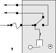
1.7The Electronic Ignition System
An ignition module mounted below the component box (located behind the control panel) is connected to an ignitor assembly at the burner. The ignition module performs four important functions: it provides fuse protection for the 24-volt circuit, provides an ignition spark, supplies voltage to the gas valve, and proofs the burner flame. The module contains a four second time delay circuit and a coil that activates the gas valve. All full
and dual vat fryers use two single-spark modules.
The ignitor assembly consists of a spark rod, an enrichment tube, and a flame sensor.
Inside the Ignition
Module
Out to Oil |
Level Sensor |
and Gas Valve |
To Alarm |
24 V + |
At start-up, the power switch on the touchscreen controller is |
|
|
|
|
|
|
H |
|
|
|
|
|
|
|
|
|
|
|
|
|
|
|
|
||||
|
|
|
|
|
|
|
|
||||||
|
|
|
|
|
|
V |
|
||||||
|
|
|
|
|
|
|
|
|
|
|
|
|
|
GND |
|
|
|
|
|
|
|
||||||
placed in the ON position, supplying approximately 24 VAC to |
|
|
|
|
|
|
|
||||||
|
|
|
|
|
|
||||||||
|
|
|
|
|
|
|
|
|
|
|
|
|
|
the heat-control circuitry in the Smart Interface Board and to one |
|
|
|
|
|
|
|
|
|
|
|
|
|
side of the heat relay coils on the Smart Interface Board. If the |
|
|
|
|
|
|
Ignition Wire Flame Sensor |
||||||
resistance in the temperature probe indicates the temperature in |
|
|
|
|
|
|
|
|
|
|
|
|
|
the frypot is below 180ºF (82ºC), the melt cycle function is activated where a timer activates for six seconds and deactivates for 24 seconds. If the temperature is 180ºF (82ºC) or above, the melt cycle is bypassed. In either case, ground is supplied to the other leg of the heat relay coils, which closes electronic switches in the 24 VAC circuit to provide current to the ignition module. Circuitry in the ignition module sends 24 VAC to the gas valve via a normally closed high-limit switch, and an oil level sensor which is controlled by electronics inside an egg shaped housing and a 7 second time delay relay board. Simultaneously, the module causes the ignitor to spark for four seconds to light the burner. A flame sensor verifies the burner ignition by measuring the flow of micro amps through the flame. If the burner does not light (or is extinguished), current to the ignition module is cut, the gas valve closes, and the ignition module “locks out” until the power switch is turned off and then back on. A probe monitors the temperature in the frypot. When the programmed setpoint temperature is reached, resistance in the probe causes the heat cycle circuitry in the SIB board to cut off current flow through the heat relay. This in turn cuts off the 24 VAC to the ignition module, causing the gas valve to close.
1-8
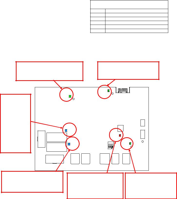
1.8Smart Interface Board (SIB)
All fryers in this series have a smart interface board (SIB) located in the component box behind the controller panel. The SIB board provides a link between the controller and the fryer’s individual components without requiring excessive wiring, and executes commands from one central point.
SMART INTERFACE BOARD LED
DIAGNOSTIC LIGHTS
LED 1 24VAC Heat Relay |
|
LED 2 12VDC to Controller |
|
LED 3 |
24VAC Latch Relay |
LED 4 |
5VDC to probes and switches |
LED 6 |
3.3VDC to Micro Processor |
LED 7 |
Communication to/from Micro Processor |
K2 is a single-pole-double throw (SPDT) relay that
supplies 24VAC to the ignition and gas valve circuits. The relays on this board are soldered to the board. If a relay fails, the board must be replaced. K1 is a single-pole-double throw (SPDT) relay that supplies voltage through the high limit and the optional air pressure switch.
The SIB LEDs (labeled LED1 through LED7) are arrayed around the board to assist in troubleshooting.
12VDC should be lit and bright at all times. If LED is dim then something is pulling voltage down. Short to ground on 12VDC circuit will cause dim LED.
When UI is soft powered on this Latch Relay LED will come on first confirming high limit is closed. The blower will then come on and prove the air switch. The relay is a true latch circuit and when broken or turned off the heat relay will also turn off.
5VDC should be lit and bright at all times. If LED is dim then something is pulling voltage down. Short to ground on 5VDC circuit will cause dim LED.
When UI calls for HEAT this LED will come on with the heat relay only after latch relay has been latched in and AIR switch has been proven. This LED will cycle with the call for heat.
Blinking red LED, (Heart Beat). This LED should be blinking and bright at all times when board is powered. The other green LED’s being dim or off will cause this LED to be off.
3.3VDC LED should be lit and bright at all times. If dim then something is pulling voltage down. Short to ground on 3.3VDC circuit will cause dim LED.
NOTE: Refer to Section 1.16.1 for troubleshooting flowchart.
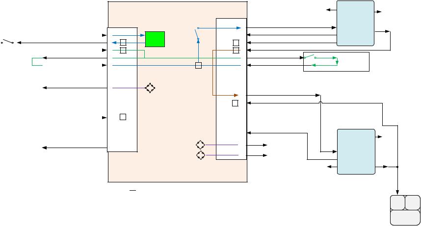
The charts on pages 1-8 and 1-9 illustrate current flow through the board, and the table at the top of page 1-10 identifies frequently used test points.
1-9
10-1
|
HIGH |
24VAC |
|||||||
|
LIMIT |
||||||||
|
|
|
|
||||||
HIGH LIMIT 24VAC |
|||||||||
|
|
|
|
|
|
||||
|
|
|
|
|
|
HIGH LIMIT RETURN 24VAC |
|||
|
|
|
|
|
|
||||
|
|
|
|
|
|
|
|
|
|
AIR BYPASS |
AIR OUT 24VAC |
||||||||
JUMPER IF AIR |
AIR IN 24VAC |
||||||||
PROVER SWITCH IS |
|||||||||
|
|
|
|||||||
NOT INSTALLED |
|
|
|
||||||
|
|
|
|
|
|
HOOD RELAY 12VDC |
|||
|
|
|
|
|
|
JUMPER |
|||
|
|
|
|
|
|
|
|
||
|
|
|
|
|
|
JUMPER |
|||
|
|
|
|
|
|
|
|
|
|
FULL VAT
TWO SINGLE SPARK
IGNITION MODULES 1ST IGNITION
MODULE
|
|
|
|
|
|
SENSE |
SPARK |
|
|
|
|
|
|
Pin 8 |
Pin 11 |
|
|
|
|
1 |
HEAT 24VAC OUT |
24V Pin 6 |
VALVE |
|
|
HEAT |
|
1st MODULE GROUND |
|||
1 |
|
|
2 |
GND Pin 5 |
Pin 3 |
||
LATCH |
RELAY |
|
1st MODULE ALARM 24VAC |
||||
3 |
CIRCUIT |
|
|
3 |
ALARM Pin 7 |
||
|
|
1st MODULE GAS VALVE 24VAC |
|||||
4 |
|
|
|
4 |
|
|
|
5 |
|
|
|
5 |
AIR OUT 24VAC |
Optional |
|
|
|
|
|
|
|||
6 |
|
|
|
6 |
AIR IN 24VAC |
AIR PROVER |
|
|
|
|
|
SWITCH |
|
||
7 |
|
|
|
7 |
|
|
|
8 |
|
|
J2 |
10 |
|
|
|
9 |
SMART |
|
11 |
2nd MODULE POWER 24VAC |
|
|
|
10 J1 |
|
|
12 |
|
|
||
|
|
2nd MODULE GAS VALVE 24VAC |
|
|
|||
11 |
INTERFACE |
|
|
14 |
|
|
|
|
|
|
|
|
|||
12 |
BOARD |
|
|
15 |
|
|
|
14 |
|
|
17 |
|
|
|
|
(SIB) |
|
|
|
2ND IGNITION |
|||
16 |
|
|
20 |
|
|||
|
|
|
2nd MODULE GROUND |
MODULE |
|||
17 |
|
|
|
13 |
|
SPARK |
|
18 |
|
|
|
|
|
|
|
|
|
|
21 |
-12VDC AC BLOWER RELAY |
|
Pin 11 |
|
20 |
|
|
|
|
|
|
|
|
|
|
|
+12VDC AC BLOWER RELAY |
24V Pin 6 |
|
|
|
|
|
|
22 |
|
||
|
|
|
|
|
|
GND Pin 5 |
|
|
|
|
|
|
|
SENSE |
VALVE |
|
|
|
|
|
|
Pin 8 |
Pin 3 |

 SENSORS
board SIB the through flow Vat Full 1.8.1
MV PV
GAS VALVE
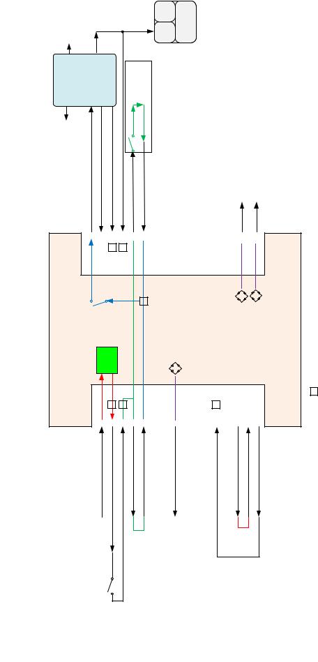
1.8.2 Split Vat flow through the SIB board
1-11

1.8.3Frequently Used Test Points for SIB (Smart Interface Board)
NOTE: DO NOT CHECK WITH HARNESSES UNPLUGGED AS SHORTING THE PINS MAY OCCUR WHICH WILL DAMAGE THE BOARD.
FREQUENTLY USED TEST POINTS FOR INTERFACE BOARD 1085980
|
Meter |
|
|
Test |
Setting |
Pins |
Results |
24VAC Power to SIB |
50VAC Scale |
1 on J1 and GROUND |
22-28 |
12VDC Power to Controller |
50VDC Scale |
7 and 8 on J6 |
12-18 |
24VAC Power to Right Module |
50VAC Scale |
1 on J2 and GROUND |
22-28 |
24VAC Power to Left Module (if present) |
50VAC Scale |
12 on J2 and GROUND |
22-28 |
120 VAC Power |
250VAC Scale |
Blower Connections |
110-125 |
120 VAC Power to Blowers |
250VAC Scale |
Blower Connections |
110-125 |
24VAC Power to High-Limit |
50VAC Scale |
3 on J1 and GROUND |
22-28 |
Probe Resistance |
R x 1000 OHMS |
Disconnect and test across probe leads |
** |
Probe Isolation |
R x 1000 OHMS |
2 on Probe Connector and GROUND |
*** |
High-Limit Continuity |
R x 1 OHM |
3 on J1 and 4 on J1 |
0 |
**See Probe Resistance Chart in section 1.17.
***5 mega-Ohms or greater.
1.8.4 SIB (Smart Interface Board) Troubleshooting
Problem |
|
Probable Causes |
|
||
No power to SIB board |
A. |
J1 connection unplugged |
B. |
Fuse blown. |
|
|
C. |
Transformer malfunction |
|
|
|
SIB BOARD 1 |
A. |
Loose wire connection. |
MISSING displayed on |
||
the controller. |
|
|
SIB BOARD 2 |
A. Loose wire connection. |
|
MISSING displayed on |
|
|
the controller. |
|
|
SIB NOT |
A. |
SIB board not configured |
CONFIGURED |
|
|
displayed on the |
|
|
controller. |
|
|
Corrective Action
A.Check to ensure J1 on front of SIB board is fully locked into connector.
B.Ensure fuse located at the bottom of the control box is not blown and cap is securely tightened.
C.Check that proper voltage is present at transformer. See table in section 1.8.3.
A.Ensure the connector is securely attached to plug J6 on the SIB board.
A.Ensure all wiring harnesses are securely connected between J9 and J10 between SIB boards.
A.Replace the SIB board.
1-12

1.8.5 SIB (Smart Interface Board) Pin Positions and Harnesses
NOTE: DO NOT CHECK WITH HARNESSES UNPLUGGED (except ATO and Temp Probes) AS SHORTING THE PINS MAY OCCUR WHICH WILL DAMAGE THE BOARD.
|
|
|
|
|
|
|
|
Pin |
|
|
|
|
|
Wire |
|
|
|
|
|
|
|
|
|
|
|
|
|
||
|
Connector |
|
From/To |
|
|
Harness # |
# |
|
Function |
|
Voltage |
|
Color |
|
|
|
|
From Transformer |
|
|
|
|
1 |
|
24VAC Input |
|
24VAC |
|
Orange |
|
|
|
|
|
|
8075888 Full |
|
2 |
|
Ground - |
|
|
|
Blue |
|
|
|
To High Limit |
|
|
8075886 Split |
|
3 |
|
24VAC Out |
|
24VAC |
|
Orange |
|
|
|
From High Limit |
|
|
|
|
4 |
|
24VAC Input |
|
24VAC |
|
Blue |
|
|
|
To Air Switch Jumper |
|
|
|
|
5 |
|
24VAC Out |
|
24VAC |
|
Gray |
|
|
|
From Air Switch Jumper |
|
|
|
|
6 |
|
24VAC Input |
|
24VAC |
|
Gray |
|
J1 |
|
To Hood Relay |
|
|
|
|
9 |
|
12VDC Out |
|
12VDC |
|
Purple |
|
|
|
|
|
|
|
10 |
|
|
|
|
|
Yellow |
|
|
|
|
|
|
|
|
|
|
|
|
|
|
||
|
|
|
|
|
|
|
|
11 |
|
24VAC Input |
|
|
|
Brown |
|
|
|
From Drain Switch Jumper |
|
|
|
|
14 |
|
|
24VAC |
|
Blue |
|
|
|
|
|
|
|
|
|
16 |
|
Ground - |
|
|
|
Blue |
|
|
|
Left SIB Jumper |
|
|
|
|
17 |
|
|
|
|
Purple |
|
|
|
|
Left SIB Jumper |
|
|
|
|
18 |
|
5VDC Out |
|
5VDC |
|
Purple |
|
|
|
To Drain Switch Jumper |
|
|
|
|
20 |
|
24VAC Out |
|
24VAC |
|
Orange |
|
|
|
To 24VAC Ignition Module |
|
|
|
|
1 |
|
24VAC Out |
|
24VAC |
|
Red |
|
|
|
From Gas Valve |
|
|
|
|
2 |
Ground |
|
|
|
Green |
|
|
|
|
From Gas Valve |
|
|
|
|
3 |
|
Alarm In |
|
24VAC |
|
Yellow |
|
|
|
From Gas Valve |
|
|
|
|
4 |
|
24VAC In |
|
24VAC |
|
Orange |
|
|
|
To Air Switch |
|
|
|
|
5 |
|
24VAC Out |
|
24VAC |
|
Orange |
|
|
|
From Air Switch |
|
|
|
|
6 |
|
2VAC In |
|
24VAC |
|
Blue |
|
J2 |
|
|
|
|
|
|
11 |
|
|
|
|
|
Blue |
|
|
To 2nd Ignition Module |
|
|
|
|
12 |
|
24VAC Out |
|
24VAC |
|
Red |
|
|
|
|
|
|
|
|
|
|
|
|||||
|
|
|
From 2nd Ignition Module |
|
|
|
|
13 |
|
Ground |
|
|
|
Green |
|
|
|
From 2nd Ignition Module |
|
|
|
|
|
|
|
|
24VAC |
|
Orange |
|
|
|
Valve |
|
|
|
|
14 |
|
24VAC In |
|
|
||
|
|
|
|
|
|
|
|
|
|
|
|
|||
|
|
|
|
|
|
|
|
15 |
|
AC Blower Relay |
|
|
|
Orange |
|
|
|
To AC Blower Relay |
|
|
|
|
21 |
|
|
-12VDC |
|
Black |
|
|
|
|
To AC Blower Relay |
|
|
|
|
22 |
|
AC Blower Relay |
|
+12VDC |
|
Yellow |
|
J3 |
|
ATO Probe |
|
8263286 |
|
1 |
|
Ground |
|
|
|
Yellow |
|
|
|
|
|
2 |
|
RTD |
|
3.3VDC |
|
Red |
||||
|
|
|
|
|
|
|
|
3 |
|
C-BUS + |
|
|
|
|
|
|
|
|
|
|
|
|
1 |
|
|
5VDC |
|
|
|
|
|
|
|
|
|
|
|
2 |
|
C-BUS - |
|
5VDC |
|
|
|
|
|
|
|
|
|
|
3 |
|
5VDC |
|
5VDC |
|
|
|
J6 |
|
Controller |
|
|
|
|
4 |
|
RS485 - |
|
5VDC |
|
|
|
|
|
|
|
|
5 |
|
RS485 + |
|
5VDC |
|
|
||
|
|
|
|
|
|
|
|
|
|
|
|
|||
|
|
|
|
|
|
|
|
6 |
|
Signal Ground |
|
|
|
|
|
|
|
|
|
|
|
|
7 |
|
12VDC |
|
12VDC |
|
|
|
|
|
|
|
|
|
|
8 |
|
Signal Ground |
|
|
|
|
|
|
|
|
|
|
|
|
1 |
|
5VDC+ |
|
+5VDC |
|
|
|
J7 |
|
C-Bus Harness |
|
|
8075549 or |
|
2 |
|
CAN High |
|
|
|
|
|
|
|
|
8075551 |
|
3 |
|
CAN Low |
|
|
|
|
||
|
|
|
|
|
|
|
|
|
|
|
||||
|
|
|
|
|
|
|
|
4 |
|
Ground |
|
|
|
|
|
|
|
C-Bus Harness or |
|
|
8075549 or |
|
1 |
|
5VDC+ |
|
+5VDC |
|
|
|
|
|
|
|
8075551 or |
|
2 |
|
CAN High |
|
|
|
|
|
|
J8 |
|
Network Resistor |
|
|
|
|
|
|
|
|
|||
|
|
|
(8075632 |
|
3 |
|
CAN Low |
|
|
|
|
|||
|
|
|
(pins 2 & 3) |
|
|
|
|
|
|
|
||||
|
|
|
|
|
Resistor) |
|
4 |
|
Ground |
|
|
|
|
|
|
|
|
|
|
|
|
|
|
|
|
|
|||
|
|
|
|
|
|
|
|
1 |
|
Ground |
|
|
|
|
|
|
|
P-Bus Power Communication |
|
|
|
|
2 |
|
P-BUS power |
|
+5VDC |
|
|
|
J9 |
|
from SIB to VIB or between |
|
|
8075555 or |
|
3 |
|
Modbus RS485 B |
|
|
|
|
|
|
SIB’s |
|
8075553 |
|
4 |
|
Modbus RS485 A |
|
|
|
|
||
|
|
|
|
|
|
|
|
|
|
|||||
|
|
|
RJ11 |
|
|
|
|
5 |
|
Signal ground |
|
|
|
|
|
|
|
|
|
|
|
|
6 |
|
P-BUS power |
|
+12VDC |
|
|
|
|
|
P-Bus Power Communication |
|
|
|
|
1 |
|
Ground |
|
|
|
|
|
J10 |
|
from SIB to VIB or between |
|
|
8075555 or |
|
2 |
|
P-BUS power |
|
+5VDC |
|
|
|
|
SIB’s |
|
8075553 |
|
3 |
|
Modbus RS485 B |
|
|
|
|
||
|
|
|
|
|
|
|
|
|
|
|||||
|
|
|
RJ11 |
|
|
|
|
4 |
|
Modbus RS485 A |
|
|
|
|
1-13
|
|
|
|
|
|
|
Pin |
|
|
|
|
|
Wire |
|
|
|
|
|
|
|
|
|
|
|
|
||
|
Connector |
|
From/To |
|
Harness # |
# |
|
Function |
|
Voltage |
|
Color |
|
|
|
|
|
|
|
|
5 |
|
Signal ground |
|
|
|
|
|
|
|
|
|
|
|
6 |
|
P-BUS power |
|
+12VDC |
|
|
|
J11 |
|
Cooking Probe |
|
8263285 |
|
1 |
|
Ground |
|
|
|
Yellow |
|
|
|
|
2 |
|
Probe |
|
3.3VDC |
|
Red |
|||
|
|
|
|
|
|
|
|
|
|
||||
1.9Thermostats
The fryers are equipped with temperature probes located on the front centerline of each frypot (dual-vat frypots have two probes, one in each vat). In this type of thermostat, the probe resistance varies directly with the temperature. That is, as the temperature rises, so does resistance, at a rate of approximately 2 ohms for every 1º F. Circuitry in the controller monitors the probe resistance and controls burner firing when the resistance exceeds or falls below programmed temperatures (set points).
The fryers are also equipped with a high-limit thermostat. In the event that the fryer fails to properly control the oil temperature, the high-limit thermostat prevents the fryer from overheating to the flash point. The high-limit thermostat acts as a normally closed power switch that opens when exposed to temperatures above 425ºF to 450ºF (218ºC to 232ºC). The different types of high limit thermostats have different part numbers for CE and Non-CE models, and are not interchangeable.
1.10Accessing Fryers for Servicing
 DANGER
Moving a fryer filled with oil may cause spilling or splattering of the hot liquid. Follow the Drain to Pan instructions in Chapter 5 of the FQGLA-T Installation and Operation Manual before attempting to relocate a fryer for servicing.
1.Shut off the gas supply to the unit. Unplug the power cords. Disconnect the unit from the gas supply.
2.Remove any attached restraining devices and relocate the fryer for service accessibility.
3.After servicing is complete, reconnect the unit to the gas supply and turn on gas supply, reattach restraining devices, and plug in the electrical cords. NOTE: To ensure the safe and efficient operation of the fryer and hood, the electrical plug for the 100-120 volt line, which may power the hood, must be fully engaged and locked in its pin and sleeve socket.
1.11Cleaning the Gas Valve Vent Tube
1.Set the fryer power switch and the gas valve to the OFF position.
2.Carefully unscrew the vent tube from the gas valve. NOTE: The vent tube may be straightened for ease of removal.
3.Pass a piece of ordinary binding wire (.052 inch diameter) through the tube to remove any obstruction.
4.Remove the wire and blow through the tube to ensure it is clear.
5.Reinstall the tube and bend it so that the opening is pointing downward.
1-14
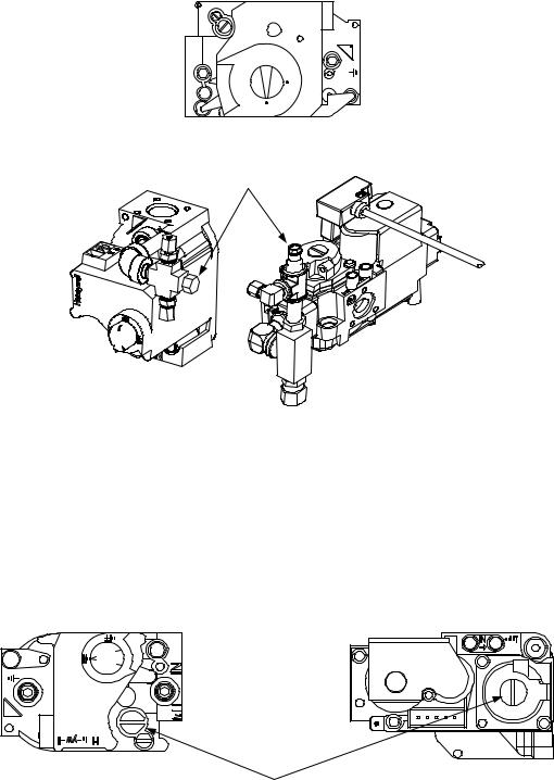
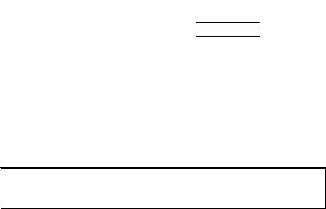
1.12Checking the Burner Manifold Gas Pressure
1. |
On non-CE fryers only ensure that the gas valve knob is in the OFF position. |
|
Honeywell |
|
ON |
|
OFF |
2. |
Remove the pressure tap plug from the gas valve assembly. |
Pressure Tap Plug
Typical Non-CE |
Typical CE Valve |
Valve Assembly |
Assembly |
3.Insert the fitting for a gas pressure-measuring device into the pressure tap hole.
4.On non-CE fryers only, place the gas valve in the ON position
5.Place the fryer power switch in the ON position. When the burner has lit and burned steadily for at least one minute, compare the gas pressure reading to the pressure for the corresponding gas in the appropriate table on the following page. The tables on the following page list the burner manifold gas pressures for each of the gas types that can be used with this equipment.
6.To adjust the burner gas pressure, remove the cap from the gas valve regulator and adjust to the correct pressure.
Non-CE |
CE |
Valve |
Valve |
GAS VALVE REGULATOR CAP
7.Place the fryer power switch (and the gas valve in non-CE fryers) in the OFF position. Remove the fitting from the pressure tap hole and reinstall the pressure tap plug.
1-15
Non-CE Standard for Gas Pressure
Fryer Model |
FQGLA30-T |
|
|
||||
Gas Type |
Nat |
LP |
|
|
|||
|
|
(Natural) |
(Propane) |
|
|
||
Incoming Min Pressure |
6/1.49/14.93 |
11/2.74/27.37 |
|
|
|||
WC/kPa/mbar |
|
|
|
|
|
|
|
Incoming Max Pressure |
14/3.48/34.84 |
14/3.48/34.84 |
|
|
|||
WC/kPa/mbar |
|
|
|
|
|
|
|
Orifice Size (mm) |
3.18 |
2.10 |
|
|
|||
|
|
|
|
|
|
|
|
Number of Orifices |
2 |
|
2 |
|
|
|
|
|
|
|
|
|
|
|
|
Burner Manifold |
3.00/0.73 |
8.25/2.5 |
|
|
|||
Pressure WC/kpa |
|
|
|
|
|
|
|
(1) mbar = 10,2 mm H2O |
|
|
|
|
|
|
|
|
|
|
|
|
|||
|
Korea Standard for Gas Pressure |
|
|||||
Fryer Model |
FQGLA30-T |
|
|||||
Gas Type |
LNG |
LPG |
|
||||
|
|
(Natural) |
(Propane) |
|
|||
Incoming Min Pressure |
4/1.00/10.00 |
9.2/2.30/23.00 |
|
|
|||
WC/kpa/mbar |
|
|
|
|
|
|
|
Incoming Max Pressure |
10/2.50/25.00 |
13.2/3.30/33.00 |
|
||||
WC/kpa/mbar |
|
|
|
|
|
|
|
Orifice Size (mm) |
3.18 |
2.10 |
|
|
|||
|
|
|
|
|
|
|
|
Number of Orifices |
2 |
|
2 |
|
|
|
|
|
|
|
|
|
|
|
|
Burner Manifold |
3.00/0.73 |
8.25/2.5 |
|
|
|||
Pressure WC/kPa |
|
|
|
|
|
|
|
(1) mbar = 10,2 mm H2O |
|
|
|
|
|
|
|
|
|
|
|
|
|||
|
Japan Standard for Gas Pressure |
|
|||||
|
Fryer Model |
|
FQGLA30-T |
|
|||
|
|
|
|
|
|
|
|
|
Gas Type |
|
13A |
|
Propane |
|
|
|
|
|
|
(LP) |
|
||
|
|
|
|
|
|
||
|
Incoming Min Pressure |
|
4/1.00/10.00 |
|
9.2/2.30/23.00 |
|
|
|
WC/kpa/mbar |
|
|
|
|
|
|
|
Incoming Max Pressure |
|
10/2.50/25.00 |
13.2/3.30/33.00 |
|
||
|
WC/kpa/mbar |
|
|
|
|
|
|
|
Orifice Size (mm) |
|
3.18 |
|
1.95 |
|
|
|
|
|
|
|
|
|
|
|
Number of Orifices |
|
2 |
|
2 |
|
|
|
|
|
|
|
|
|
|
|
Burner Manifold |
|
3.00/0.73 |
|
8.25/2.5 |
|
|
|
Pressure WC/kPa |
|
|
|
|
|
|
|
(1) mbar = 10,2 mm H2O |
|
|
|
|
|
|
CE Standard for Gas Pressure
Fryer Model |
FQGA30-T |
|
|
|
Gas Type |
G20 |
G25 |
G30 |
G31 |
|
Natural |
Natural |
Butane |
Propane |
|
Gas |
Gas |
/Propane |
|
|
Lacq |
Groniqu |
|
|
|
|
e |
|
|
Incoming Min |
20 |
20 |
28/30 |
37 |
Pressure (mbar) |
|
|
|
|
Incoming Max |
20 |
25 |
50 |
50 |
Pressure (mbar) |
|
|
|
|
Orifice Size (mm) |
3.18 |
3.18 |
1.95 |
1.95 |
|
|
|
|
|
Number of |
2 |
2 |
2 |
2 |
Orifices |
|
|
|
|
Regulator |
7 |
10 |
17 |
20.6 |
Pressure Full Vat |
|
|
|
|
(mbar) |
|
|
|
|
Regulator |
8 |
11.2 |
17 |
20.6 |
Pressure Dual Vat |
|
|
|
|
(mbar) |
|
|
|
|
Burner Manifold |
7 |
10 |
17 |
20.6 |
Pressure (mbar) |
|
|
|
|
Full Vat |
|
|
|
|
Burner Manifold |
8 |
11.2 |
17 |
20.6 |
Pressure (mbar) |
|
|
|
|
1-16

Flame Sensor
Wire
1.13Measuring Flame Current
When the burner flame is properly adjusted, it will produce a current between 2.0 A and 2.5 A on Fenwal modules. Lockouts can occur at currents 0.5 A or below on Fenwal modules. Flame current is measured by placing a microamp (not milliamp) meter in series with the sensing wire on the ignitor. This is accomplished as follows:
1.Place the controller power switch in the OFF position.
2.Disconnect the sensing wire from one of the burner ignitors (see Figure 1) and connect it to the positive lead of the meter. Connect the negative lead of the meter to the terminal from which the sensing wire was removed.
3. Place the controller power switch in the ON position to light the burners. After the frypot temperature reaches 200 F (93 C), wait at least one minute before
checking the reading. NOTE: The closer the unit is to normal operating temperature, the more accurate the reading will be.
1.14Replacing Fryer Components
1.14.1 Replacing the Controller or the Controller Wiring Harnesses
1.Disconnect the fryer from the electrical power supply. The fuse located at the bottom of the control box can be removed to remove power from individual control boxes.
2.The controller is held in place by two screws in upper corners.
3.Remove the two screws from the upper corners of the controller.
4.Slide the controller up and it and will swing open from the top.
5.Disconnect the RJ45 cable from the SIB board first.
6.Disconnect the other cables from the connectors on the back of the controller marking their position for
reassembly.
7.Disconnect the lanyard tether.
8.Remove the controller.
Speaker
Harness
Locator Wire 
USB Harness
Figure 2
RJ-45 Power / |
|
|
Communication |
Ground Wire |
Lanyard Tether |
|
|
5.With the replacement controller face down resting in the control box, reattach the lanyard tether first. Failure to reinstall lanyard could result in damage to the SIB board.
6.Reinstall the controller by reversing steps 1 thru 6.
7.Setup the controller following the instructions in section 4.7 of the FQGLA-T Installation and Operation manual. If the controller being replaced is in the far left position the current date and time will need to be setup following the instruction in section 4.8 of the Installation and Operation manual. Setup MUST be performed prior to reset.
8.Once setup is complete on all replaced controllers, CYCLE POWER TO ENTIRE FRYER SYSTEM. See section 1.19.2 to reset control power.
1-17
 Loading...