


FilterQuick™ FQG30
Gas Fryer
Service Manual
This manual is updated as new information and models are released. Visit our website for the latest manual.
FOR YOUR SAFETY
Do Not Store or use gasoline or other flammable vapors and liquids in the vicinity of this or any other appliance.
*8197109*
Part Number: FRY_SM_8197109 02/2016
Original Instructions
NOTICE
IF, DURING THE WARRANTY PERIOD, THE CUSTOMER USES A PART FOR THIS MANITOWOC FOOD SERVICE EQUIPMENT OTHER THAN AN UNMODIFIED NEW OR RECYCLED PART PURCHASED DIRECTLY FROM FRYMASTER OR ANY OF ITS AUTHORIZED SERVICERS, AND/OR THE PART BEING USED IS MODIFIED FROM ITS ORIGINAL CONFIGURATION, THIS WARRANTY WILL BE VOID. FURTHER, FRYMASTER AND ITS AFFILIATES WILL NOT BE LIABLE FOR ANY CLAIMS, DAMAGES OR EXPENSES INCURRED BY THE CUSTOMER WHICH ARISE DIRECTLY OR INDIRECTLY, IN WHOLE OR IN PART, DUE TO THE INSTALLATION OF ANY MODIFIED PART AND/OR PART RECEIVED FROM AN UNAUTHORIZED SERVICER.
NOTICE
This appliance is intended for professional use only and is to be operated by qualified personnel only. A Frymaster Factory Authorized Servicer (FAS) or other qualified professional should perform installation, maintenance, and repairs. Installation, maintenance, or repairs by unqualified personnel may void the manufacturer’s warranty. See Chapter 1 of this manual for definitions of qualified personnel.
NOTICE
This equipment must be installed in accordance with the appropriate national and local codes of the country and/or region in which the appliance is installed. See NATIONAL CODE REQUIREMENTS in Chapter 2 of this manual for specifics.
NOTICE TO U.S. CUSTOMERS
This equipment is to be installed in compliance with the basic plumbing code of the Building Officials and Code Administrators International, Inc. (BOCA) and the Food Service Sanitation Manual of the U.S. Food and Drug Administration.
NOTICE
Drawings and photos used in this manual are intended to illustrate operational, cleaning and technical procedures and may not conform to onsite management operational procedures.
NOTICE
This appliance is intended to be used for commercial applications, for example in kitchens of restaurants, canteens, hospitals and in commercial enterprises such as bakeries, butcheries, etc., but not for continuous mass production of food.
NOTICE TO OWNERS OF UNITS EQUIPPED WITH CONTROLLERS
U.S.
This device complies with Part 15 of the FCC rules. Operation is subject to the following two conditions: 1) This device may not cause harmful interference, and 2) This device must accept any interference received, including interference that may cause undesired operation. While this device is a verified Class A device, it has been shown to meet the Class B limits.
CANADA
This digital apparatus does not exceed the Class A or B limits for radio noise emissions as set out by the ICES-003 standard of the Canadian Department of Communications.
 DANGER
Improper installation, adjustment, maintenance or service, and unauthorized alterations or modifications can cause property damage, injury, or death. Read the installation, operating, and service instructions thoroughly before installing or servicing this equipment. Only qualified service personnel may convert this appliance to use a gas other than that for which it was originally configured.
 DANGER
No structural material on the fryer should be altered or removed to accommodate placement of the fryer under a hood. Questions? Call the Frymaster Service Hotline at 1-800-551-8633.
 WARNING
After installation of a gas fryer and after any maintenance to the gas system of a gas fryer-manifold, valve, burners, etc. – check for gas leaks at all connections. Apply a thick soapy solution to all connections and ensure there are no bubbles. There should be no smell of gas.
NOTICE
The Commonwealth of Massachusetts requires any and all gas products to be installed by a licensed plumber or pipe fitter.

 DANGER
Adequate means must be provided to limit the movement of this appliance without depending upon the gas line connection. Single fryers equipped with legs must be stabilized by installing anchor straps. All fryers equipped with casters must be stabilized by installing restraining chains. If a flexible gas line is used, an additional restraining cable must be connected at all times when the fryer is in use.
 CAUTION
No warranty is provided for any Frymaster fryer used in a mobile or marine installation or concession. Warranty protection is only offered for fryers installed in accordance with the procedures described in this manual. Mobile, marine or concession conditions of this fryer should be avoided to ensure optimum performance.
 DANGER
The front ledge of the fryer is not a step! Do not stand on the fryer. Serious injury can result from slips or contact with the hot oil.
 DANGER
Do not store or use gasoline or other flammable liquids or vapors in the vicinity of this or any other appliance.
 DANGER
Do not spray aerosols in the vicinity of this appliance while it is in operation.
 DANGER
Instructions to be followed in the event the operator smells gas or otherwise detects a gas leak must be posted in a prominent location. This information can be obtained from the local gas company or gas supplier.
 DANGER
This product contains chemicals known to the state of California to cause cancer and/or birth defects or other reproductive harm.
Operation, installation, and servicing of this product could expose you to airborne particles of glasswool or ceramic fibers, crystalline silica, and/or carbon monoxide. Inhalation of airborne particles of glasswool or ceramic fibers is known to the State of California to cause cancer. Inhalation of carbon monoxide is known to the State of California to cause birth defects or other reproductive harm.
 DANGER
The crumb tray in fryers equipped with a filter system must be emptied into a fireproof container at the end of frying operations each day. Some food particles can spontaneously combust if left soaking in certain shortening material.
 WARNING
Do not bang fry baskets or other utensils on the fryer’s joiner strip. The strip is present to seal the joint between the fry vessels. Banging fry baskets on the strip to dislodge shortening will distort the strip, adversely affecting its fit. It is designed for a tight fit and should only be removed for cleaning.
 DANGER
Improper installation, adjustment, maintenance or service, and unauthorized alterations or modifications can cause property damage, injury, or death. Read the installation, operating, and service instructions thoroughly before installing or servicing this equipment.
NOTICE
The appliance must be installed and used in such a way that any water cannot contact the fat or oil.
 DANGER
Keep all items out of drains. Closing actuators may cause damage or injury.
 DANGER
Prior to movement, testing, maintenance and any repair on your Frymaster fryer; disconnect ALL electrical power cords from the electrical power supply.
 WARNING
Use caution and wear appropriate safety equipment to avoid contact with hot oil or surfaces that may cause severe burns or injury.
ii

FILTERQUICK™ FQG30 SERIES GAS FRYERS
SERVICE MANUAL
TABLE OF CONTENTS
CHAPTER 1: Service Procedures |
|
||
1.1 |
Functional Description............................................................................................................................................................ |
1-1 |
|
1.2 |
The Electronic Ignition System............................................................................................................................................. |
1-1 |
|
1.3 |
Interface Board .......................................................................................................................................................................... |
1-2 |
|
1.4 |
Thermostats................................................................................................................................................................................ |
1-4 |
|
1.5 |
Accessing Fryers for Servicing .............................................................................................................................................. |
1-4 |
|
1.6 |
Cleaning the Gas Valve Vent Tube...................................................................................................................................... |
1-4 |
|
1.7 |
Checking the Burner Manifold Gas Pressure ................................................................................................................... |
1-5 |
|
1.8 |
Measuring Flame Current ...................................................................................................................................................... |
1-6 |
|
1.9 |
Replacing Fryer Components ............................................................................................................................................... |
1-6 |
|
|
1.9.1 |
Replacing the Controller or the Controller Wiring Harness .................................................................. |
1-6 |
|
1.9.2 |
Replacing the Temperature Probe or High-Limit Thermostat ............................................................. |
1-7 |
|
1.9.3 |
Replacing the Interface Board......................................................................................................................... |
1-7 |
|
1.9.4 |
Replacing an Ignition Module......................................................................................................................... |
1-8 |
|
1.9.5 |
Replacing an Ignitor Assembly ....................................................................................................................... |
1-8 |
|
1.9.6 |
Replacing or Cleaning a Combustion Air Blower...................................................................................... |
1-8 |
|
1.9.7 |
Adjusting the Air/Gas Mixture...................................................................................................................... |
1-10 |
|
1.9.8 |
Replacing a Gas Valve ..................................................................................................................................... |
1-10 |
|
1.9.9 |
Replacing a Burner Assembly....................................................................................................................... |
1-11 |
|
1.9.10 |
Replacing the Filter Motor, Filter Pump, or Filter Pump...................................................................... |
1-12 |
|
1.9.11 |
Replacing the Frypot....................................................................................................................................... |
1-12 |
|
1.9.12 |
Replacing Frypot Insulation and/or Upper Burner Rails...................................................................... |
1-13 |
1.10 Troubleshooting and Problem Isolation............................................................................................................................ |
1-16 |
||
|
1.10.1 |
Heating (Ignition) Failure............................................................................................................................... |
1-16 |
|
1.10.2 |
Improper Burner Function............................................................................................................................. |
1-17 |
|
1.10.3 |
Improper Temperature Control................................................................................................................... |
1-18 |
|
1.10.4 |
Controller Malfunctions ................................................................................................................................. |
1-19 |
|
1.10.5 |
Filtration Malfunctions ................................................................................................................................... |
1-19 |
|
1.10.6 |
Leakage................................................................................................................................................................ |
1-20 |
1.11 |
Troubleshooting Guides...................................................................................................................................................... |
1-20 |
|
|
1.11.1 |
Troubleshooting the 24 VAC Circuit .......................................................................................................... |
1-20 |
|
1.11.2 |
Troubleshooting the Gas Valve ................................................................................................................... |
1-22 |
|
1.11.3 |
Troubleshooting the Temperature Probe................................................................................................ |
1-23 |
|
1.11.4 |
Replacing the Transformer or Filter Relay................................................................................................ |
1-23 |
1.12 |
Basket Lift Service Procedures........................................................................................................................................... |
1-24 |
|
1.13 |
Probe Resistance Chart ........................................................................................................................................................ |
1-26 |
|
1.14 |
ATO (Automatic Top-Off ) Service Procedures............................................................................................................. |
1-26 |
|
|
1.14.1 |
ATO (Automatic Top-Off Troubleshooting)............................................................................................. |
1-26 |
|
1.14.2 |
ATO (Automatic Top-Off Troubleshooting) Board Pins and Positions ........................................... |
1-28 |
|
1.14.3 |
Replacing the ATO Board or Transformer ................................................................................................ |
1-29 |
|
1.14.4 |
Replacing the ATO Pump or Solenoid....................................................................................................... |
1-29 |
1.15 |
MIB (Manual Interface Board) Service Procedures...................................................................................................... |
1-29 |
|
|
1.15.1 |
Manually Draining, Refilling or Filtering Using the MIB Board.......................................................... |
1-30 |
|
1.15.2 |
MIB (Manual Interface Board) Troubleshooting..................................................................................... |
1-31 |
|
1.15.3 |
MIB (Manual Interface Board) Pin Positions and Harnesses............................................................... |
1-33 |
|
1.15.4 |
MIB (Manual Interface Board) Display Characters ................................................................................. |
1-34 |
|
1.15.5 |
Replacing the MIB Board................................................................................................................................ |
1-34 |
|
1.15.6 |
Control Power Reset Switch.......................................................................................................................... |
1-35 |
1.16 |
Bulk Oil Service Issues........................................................................................................................................................... |
1-35 |
|
|
1.16.1 |
Bulk MIB Tests.................................................................................................................................................... |
1-35 |
|
1.16.2 |
Bulk Wiring.......................................................................................................................................................... |
1-36 |
|
1.16.3 |
Bulk Oil Plumbing Schematic ....................................................................................................................... |
1-37 |
|
1.16.4 |
Bulk Oil Test Quick Reference....................................................................................................................... |
1-37 |
1.17 |
AIF (Automatic Intermittent Filtration) Service Procedures.................................................................................... |
1-39 |
|
|
1.17.1 |
AIF (Automatic Intermittent Filtration) Troubleshooting ................................................................... |
1-39 |
|
1.17.2 |
AIF (Automatic Intermittent Filtration) Actuator Board Pin Positions............................................ |
1-41 |
i
|
1.17.3 |
Replacing an AIF (Automatic Intermittent Filtration) Board............................................................... |
1-42 |
|
1.17.4 |
Replacing a Rotary Actuator.......................................................................................................................... |
1-42 |
|
1.17.5 |
Oil Level Sensor ................................................................................................................................................. |
1-42 |
|
|
1.17.5.1 Oil Level Sensor Troubleshooting.......................................................................................... |
1-43 |
|
|
1.17.5.2 Oil Level Sensor Diagram .......................................................................................................... |
1-44 |
1.18 |
FilterQuick™ Controller Service Procedures.................................................................................................................... |
1-44 |
|
|
1.18.1 |
FilterQuick™ Controller Troubleshooting........................................................................................................ |
1-44 |
|
1.18.2 |
FilterQuick™ Useful Codes and Passwords ..................................................................................................... |
1-47 |
|
1.18.3 |
Service Required Errors........................................................................................................................................ |
1-48 |
|
1.18.4 |
Error Log Codes...................................................................................................................................................... |
1-48 |
|
1.18.5 |
FilterQuick™ Filter Error Flowchart .................................................................................................................... |
1-50 |
|
1.18.6 Clogged Drain/Failed Oil Sensor Flowchart ................................................................................................. |
1-51 |
|
|
1.18.7 |
Menu Trees .............................................................................................................................................................. |
1-52 |
|
|
1.18.7.1 FilterQuick™ Controller Setup Menu Tree .................................................................................. |
1-52 |
|
|
1.18.7.2 FilterQuick™ Filter and Info Mode Menu Tree........................................................................... |
1-53 |
|
1.18.8 FilterQuick™ Board Pin Positions and Harnesses.......................................................................................... |
1-54 |
|
|
1.18.9 OQS (Oil Quality Sensor) Troubleshooting ................................................................................................... |
1-55 |
|
1.19 |
Loading and Updating Software Procedures................................................................................................................ |
1-56 |
|
1.20 |
Principal Wiring Connections............................................................................................................................................. |
1-57 |
|
1.21 |
Wiring Diagrams ..................................................................................................................................................................... |
1-58 |
|
|
1.21.1 |
Main FQG 230/430 120V/CE/Export............................................................................................................ |
1-58 |
|
1.21.2 |
Main FQG 230/430 Australia.......................................................................................................................... |
1-59 |
|
1.21.3 |
Main FQG 230/430 120V/CE/Export with Solid Shortening................................................................ |
1-60 |
|
1.21.4 |
Main FQG 230/430 Australia with Solid Shortening.............................................................................. |
1-61 |
|
1.21.5 |
Main FQG 330/530 120V/CE/Export............................................................................................................ |
1-62 |
|
1.21.6 |
Main FQG 330/530 Australia.......................................................................................................................... |
1-63 |
|
1.21.7 |
Main FQG 330/530 120V/CE/Export with Solid Shortening................................................................ |
1-64 |
|
1.21.8 |
Main FQG 330/530 Australia with Solid Shortening.............................................................................. |
1-65 |
|
1.21.9 |
Transformer/Filter Box 430/530 ................................................................................................................... |
1-66 |
1.22 |
Simplified Wiring Diagrams ................................................................................................................................................ |
1-67 |
|
|
1.22.1 |
FilterQuick™ FQG30 Series Simplified Wiring with Push Pull Handles.............................................. |
1-67 |
|
1.22.2 |
FilterQuick™ FQG30 Series Simplified Wiring with Push Pull Handles.............................................. |
1-68 |
|
1.22.3 |
FilterQuick™ FQG30 Series Data Network Flowchart.............................................................................. |
1-69 |
1.23 |
Alternate Time Delay Relay Wiring Diagrams............................................................................................................... |
1-70 |
|
1.24 |
Shortening Melting Unit Wiring Diagram ...................................................................................................................... |
1-71 |
|
1.25 |
Basket Lift 100-120v Wiring Diagram .............................................................................................................................. |
1-72 |
|
1.26 |
Basket Lift 208-250v Wiring Diagram .............................................................................................................................. |
1-73 |
|
ii

FILTERQUICK™ FQG30 SERIES GAS FRYERS
CHAPTER 1: SERVICE PROCEDURES
1.1Functional Description
FilterQuick™ FQG30 Series gas fryers contain a welded stainless steel frypot that is directly heated by a high efficiency infrared burner system, requiring approximately 43% less energy than conventional burners to cook the same volume.
Self-contained combustion chambers (referred to as “burners”) are fitted into rails attached to the sides of the frypot, one on each side. Each combustion chamber is fitted with special ceramic tiles that are heated by the burning of a forced air/gas mixture. The tiles transfer heat to the frypot by means of infrared radiation, providing much more constant and uniform heat dispersion over the surface of the frypot than do conventional burners. Because less heat is lost to the atmosphere in the process, compared to “open-burner” designs, less fuel is required to achieve and maintain a given frypot temperature.
In full-vat units, gas flow to both of the burners is regulated by one electromechanical gas valve. In dual-vat units, each burner has its own valve. All fryers in this series are equipped with 24 VAC gas valve systems, and all are configured with electronic ignition.
1.2The Electronic Ignition System
An ignition module mounted below the component box (located behind the control panel) is connected to an ignitor assembly at the burner. The ignition module performs four important functions: it provides fuse protection for the 24-volt circuit, provides an ignition spark, supplies voltage to the gas valve, and proofs the burner flame. The module contains a four second time delay circuit and a coil that activates the gas valve. All full
and dual vat fryers use two single-spark modules.
The ignitor assembly consists of a spark plug, an enrichment tube, and a flame sensor.
Inside the Ignition
Module
Out to Oil |
Level Sensor |
and Gas Valve |
To Alarm |
24 V + |
At start-up, the power switch is placed in the ON position, |
|
|
|
|
|
|
H |
|
|
|
|
|
|
|
|
|
|
|
|
|
|
|
|
||||
|
|
|
|
|
|
|
|
||||||
|
|
|
|
|
|
V |
|
||||||
|
|
|
|
|
|
|
|
|
|
|
|
|
|
GND |
|
|
|
|
|
|
|
||||||
supplying approximately 12-volts DC to the heat-control |
|
|
|
|
|
|
|
||||||
|
|
|
|
|
|
||||||||
|
|
|
|
|
|
|
|
|
|
|
|
|
|
circuitry in the controller and to one side of the heat relay coils |
|
|
|
|
|
|
|
|
|
|
|
|
|
on the interface board. If resistance in the temperature probe |
|
|
|
|
|
|
Ignition Wire Flame Sensor |
||||||
indicates the temperature in the frypot is below 180ºF (82ºC), |
|
|
|
|
|
|
|
|
|
|
|
|
|
the current flows through a melt cycle circuit where a timer switch alternately closes for six seconds and opens for 24 seconds. If the temperature is 180ºF (82ºC) or above, the current flows through a heat circuit, bypassing the timer switch. In either case, ground is supplied to the other leg of the heat relay coils, which closes electronic switches in the 24 VAC circuit to provide current to the ignition module. Circuitry in the ignition module sends 24 VAC to the gas valve via a normally closed high-limit switch, and an oil level sensor which is controlled by electronics inside an egg shaped housing. Simultaneously, the module causes the ignitor to spark for four seconds to light the burner. A flame sensor verifies the burner ignition by measuring the flow of micro amps through the flame. If the burner does not light (or is extinguished), current to the ignition module is cut, the gas valve closes, and the ignition module “locks out” until the power switch is turned off and then back on. A probe monitors the temperature in the frypot. When the programmed setpoint temperature is reached, resistance in the probe causes the heat cycle circuitry in the controller to cut off current flow through the heat relay. This in turn cuts off the 24 VAC to the ignition module, causing the gas valve to close.
1-1
The blower is on during the heating cycle. The blower also turns on if the oil temperature exceeds 2°F above setpoint and during filtration to help cool the frypot to minimize caramelization of the oil on the frypot interior.
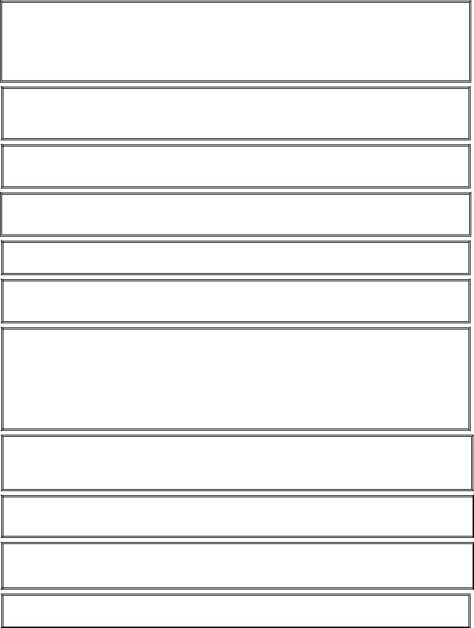
1.3Interface Board
All fryers in this series have an interface board located in the component box behind the control panel. The interface board provides a link between the controller and the fryer’s individual components without requiring excessive wiring, and allows the controller to execute commands from one central point.
K2 and K3 are double-pole-double throw (DPDT) relays that supply 24VAC to the ignition and gas valve circuits, as well as 120VAC to the blower motor. The relays on this board plug into sockets. If a relay fails, that relay can be replaced. K1 and K4 are single-pole-double throw (SPDT) relays that supply voltage to the basket lifts.
LEDs (labeled D1 through D7) are arrayed around the board to assist in troubleshooting.
SOUND 2 |
|
1 |
J2 |
|
|
|
|
|
|
|
|
|
||
|
|
|
|
|
|
|
|
|
|
|
||||
|
3 |
|
|
|
1 |
4 |
7 |
10 |
13 |
|
F2 |
Ignition |
|
|
|
|
|
|
|
|
|
|
|
|
|
|
|||
|
|
|
|
J6 |
2 |
5 |
8 |
11 |
14 |
D6 |
3 AMP Module D7 |
|||
|
J8 |
J7 |
|
3 |
6 |
9 |
12 |
15 |
|
|
|
AIR |
||
|
|
|
|
|
|
|
||||||||
|
|
|
|
12V |
|
|
|
|||||||
|
|
|
|
|
|
|
|
|
|
|
|
|
|
|
|
3 |
6 |
9 |
12 |
|
|
|
|
|
3 |
6 |
9 |
12 |
|
J1 |
2 |
5 |
8 |
11 |
|
|
|
|
|
2 |
5 |
8 |
11 |
J3 |
|
1 |
4 |
7 |
10 |
|
|
|
|
|
1 |
4 |
7 |
10 |
|
AD
AS
GND GND
|
|
|
|
|
D1 |
|
K1 |
|
|
|
|
K4 |
|
||||||
|
|
|
|
|
|
|
|
|
|
|
|
|
|
|
|
|
|
||
|
|
|
|
|
GV |
LEFT |
|
|
|
|
|
|
RIGHT |
||||||
|
|
|
|
|
|
|
|
|
|
|
|
BASKET |
|
|
|
|
|
|
BASKET |
|
|
|
|
|
|
|
|
|
|
|
|
LIFT |
|
|
|
|
|
|
LIFT |
|
|
|
|
|
GND |
RELAY |
|
D3 |
|
RELAY |
|||||||||
|
|
|
|
|
|
|
|
|
|||||||||||
|
|
|
|
|
|
|
|
||||||||||||
|
|
|
|
|
V2D |
HEAT |
|
|
|
|
|
|
HEAT |
||||||
|
|
|
|
|
PWR D2 |
|
24V |
|
|||||||||||
|
|
|
|
|
RELAY |
|
|
RELAY |
|||||||||||
|
|
|
|
|
V2S |
|
|
|
|
|
|
|
|
|
|||||
|
|
|
|
|
|
|
PWR |
AND |
|
|
|
|
|
|
AND |
||||
|
|
|
|
|
|
|
|
|
|
|
|
BLOWER |
|
|
|
|
|
|
BLOWER |
|
|
|
|
|
|
|
|
|
|
|
|
MOTOR |
|
|
|
|
|
|
MOTOR |
|
|
|
|
|
|
|
|
|
|
|
|
RELAY |
K2 |
|
|
|
|
K3 |
RELAY |
F1 |
|
|
|
|
|
D5 |
|||
|
|
|
|
|
|
|
|
|
|
Blower |
|
|
|
|
GV |
||||
Motor |
|
|
|
|
|||||
|
|
|
|
|
|
|
|
||
3 AMP |
|
|
|
|
|
|
|
|
|
|
|
|
|
|
|
|
|
|
|
|
|
|
|
|
|
|
|
|
|
|
|
|
|
|
|
|
|
|
|
V1S |
|
|
|
|
|
GND |
|||
|
|
|
|||||||
PWR |
|
|
|
|
|
GND |
|||
|
|
|
|||||||
V1D |
|
|
|
|
|
ALR |
|||
|
|
|
|
||||||
GND |
|
|
|
|
|
||||
|
|
|
|||||||
D4 |
|
|
|
|
|||||
|
|
|
|
||||||
|
|
|
|
|
|
|
|
|
|
PWR |
|
|
|
|
|||||
INTERFACE BOARD
LED DIAGNOSTIC LIGHTS
D1 24 VAC to left gas valve (dual vat only)
D2 24 VAC to left ignition module
D3 24 VAC from transformer
D4 24 VAC to right ignition module
D5 24 VAC to gas valve (right valve if dual vat)
D6 12 VAC from transformer
D7 CE and Japanese units only: air switch closed
NOTE: Refer to Section 1.11.1 on page 1-20 for troubleshooting flowchart.
SMT INTERFACE BOARD KIT 826-2264 (106-6706)
NOTE: In full-vat fryers, the relay for the left side (K2) may not be present.
The chart on the following page illustrates current flow through the board, and the table at the top of page 1-4 identifies frequently used test points.
1-2

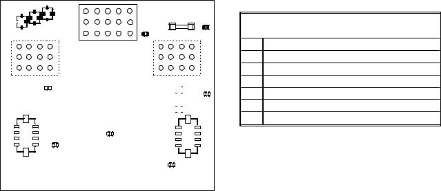
1-3 |

FREQUENTLY USED TEST POINTS FOR INTERFACE BOARD 106-6706
|
Meter |
|
|
Test |
Setting |
Pins |
Results |
12VAC Power to Controller |
50VAC Scale |
1 and 3 on J3 or J2 |
12-18 |
24VAC Power to Right Module |
50VAC Scale |
8 on J3 and GROUND |
22-28 |
24VAC Power to Left Module (if present) |
50VAC Scale |
8 on J1 and GROUND |
22-28 |
120 VAC Power |
250VAC Scale |
11 on J3 and GROUND |
110-125 |
120 VAC Power to Blowers |
250VAC Scale |
12 on J3 and GROUND |
110-125 |
24VAC Power to Fullor Right-vat High-Limit |
50VAC Scale |
9 on J3 and GROUND |
22-28 |
24VAC Power to Left High-Limit (if present) |
50VAC Scale |
9 on J1 and GROUND |
22-28 |
Probe Resistance (Fullor Right-vat) * |
R x 1000 OHMS |
2 and 6 on J3 or 13 and 14 on J2 |
** |
Probe Resistance (Left - if present) * |
R x 1000 OHMS |
2 and 6 on J1 or 14 and 15 on J2 |
** |
Probe Isolation |
R x 1000 OHMS |
6 on J1 or J3 and GROUND |
*** |
High-Limit Continuity (Fullor Right-vat) |
R x 1 OHM |
9 on J3 and Wire 13C on Gas Valve |
0 |
High-Limit Continuity (Left - if present) |
R x 1 OHM |
9 on J1 and Wire 12C on Gas Valve |
0 |
*Disconnect 20-pin harness from controller before testing probe circuit.
**See Probe Resistance Chart at end of chapter.
***5 mega-Ohms or greater.
1.4Thermostats
FilterQuick™ FQG30 Series gas fryers have temperature probes located on the front centerline of each frypot (dual-vat frypots have two probes, one in each vat). In this type of thermostat, the probe resistance varies directly with the temperature. That is, as the temperature rises, so does resistance, at a rate of approximately 2 ohms for every 1º F. Circuitry in the controller monitors the probe resistance and controls burner firing when the resistance exceeds or falls below programmed temperatures (setpoints).
FilterQuick™ FQG30 Series gas fryers are also equipped with a high-limit thermostat. In the event that the fryer fails to properly control the oil temperature, the high-limit thermostat prevents the fryer from overheating to the flash point. The high-limit thermostat acts as a normally closed power switch that opens when exposed to temperatures above 425ºF to 450ºF (218ºC to 232ºC). The different types of thermostats have different part numbers for CE and Non-CE models, and are not interchangeable.
1.5Accessing Fryers for Servicing
 DANGER
Moving a fryer filled with oil may cause spilling or splattering of the hot liquid. Follow the draining instructions on page 1-13 thru 1-15 of the FilterQuick™ Controller Manual (P/N 819-7050) before attempting to relocate a fryer for servicing.
1.Shut off the gas supply to the unit. Unplug the power cords. Disconnect the unit from the gas supply.
2.Remove any attached restraining devices and relocate the fryer for service accessibility.
3.After servicing is complete, reconnect the unit to the gas supply, reattach restraining devices, and plug in the electrical cords.
1.6Cleaning the Gas Valve Vent Tube
1.Set the fryer power switch and the gas valve to the OFF position.
2.Carefully unscrew the vent tube from the gas valve. NOTE: The vent tube may be straightened for ease of removal.
3.Pass a piece of ordinary binding wire (.052 inch diameter) through the tube to remove any obstruction.
4.Remove the wire and blow through the tube to ensure it is clear.
5.Reinstall the tube and bend it so that the opening is pointing downward.
1-4

1.7Checking the Burner Manifold Gas Pressure
1. On non-CE fryers only ensure that the gas valve knob is in the OFF position.
Honeywell |
ON |
OFF |
2. Remove the pressure tap plug from the gas valve assembly.
Pressure Tap Plug
Typical Non-CE |
Typical CE Valve |
Valve Assembly |
Assembly |
3.Insert the fitting for a gas pressure-measuring device into the pressure tap hole.
4.On non-CE fryers only, place the gas valve in the ON position
5.Place the fryer power switch in the ON position. When the burner has lit and burned steadily for at least one minute, compare the gas pressure reading to the pressure for the corresponding gas in the appropriate table on the following page. The tables list the burner manifold gas pressures for each of the gas types that can be used with this equipment.
CE Standard
Burner Manifold Gas Pressures
|
Pressure (mbar) |
|
|
|
|
|
|
|
|
|
Single |
Dual |
|
|
Gas |
Vat |
Vat |
|
|
Natural Gas Lacq |
7 |
8 |
|
|
(G20) under 20 mbar |
|
|
||
|
|
|
|
|
Natural Gas Gronique * |
10 |
11.2 |
|
|
(G25) under 25 mbar |
|
|
||
|
|
|
|
|
Natural Gas Gronique |
10 |
11.2 |
|
|
(G25) under 20 mbar |
|
|
||
|
|
|
|
|
Butane/Propane |
17 |
17 |
|
|
(G30) at 28/30 or 50 mbar |
|
|
||
|
|
|
|
|
Propane |
20.6 |
20.6 |
|
|
(G31) under 37 or 50 mbar |
|
|
||
|
|
|
|
|
Non-CE Standard
Burner Manifold Gas Pressures
Gas |
Pressure |
|
|
Natural |
3.20" W.C. |
|
|
0.80 kPa |
|
|
|
|
|
|
|
Propane |
8.25" W.C. |
|
|
2.5 kPa |
|
|
|
|
|
|
|
|
|
|
|
|
|
|
|
* Belgian G25 = 7,0 mbar (single or dual)
1-5
6.To adjust the burner gas pressure, remove the cap from the gas valve regulator and adjust to the correct pressure.
Non-CE |
CE |
Valve |
Valve |
GAS VALVE REGULATOR CAP
7.Place the fryer power switch (and the gas valve in non-CE fryers) in the OFF position. Remove the fitting from the pressure tap hole and reinstall the pressure tap plug.
1.8Measuring Flame Current
When the burner flame is properly adjusted, it will typically produce a current between 0.3 A and 0.9 A on Capable Control modules or between 3.0 A and 8.0 A on Honeywell modules. Lockouts can occur at currents 0.15 A or below on Capable Control modules or 0.9 A or below on Honeywell modules. Flame current is measured by placing a microamp (not milliamp) meter in series with the sensing wire on the ignitor. This is accomplished as follows:
1.Place the fryer power switch in the OFF position.
2.Disconnect the sensing wire from one of the burner ignitors and connect it to the positive lead of the meter. Connect the negative lead of the meter to the terminal from which the sensing wire was removed.
Flame Sensor Wire
3.Place the fryer power switch in the ON position to light the burners. After the frypot temperature reaches 200 F (93 C), wait at least one minute before checking the reading. NOTE: The closer the unit is to normal operating temperature, the more accurate the reading will be.
1.9Replacing Fryer Components
1.9.1 Replacing the Controller or the Controller Wiring Harnesses
1.Disconnect the fryer from the electrical power supply.
2.Unscrew the filter push pull handle knobs.
3.Open the control panel by removing the screws on the bottom of the bezel. Carefully lower the bezel.
4.Remove the two screws from the upper corners of the controller. The controller is hinged at the bottom and will swing open from the top.
5.Unplug the wiring harnesses from the connectors on the back of the controller marking their position for reassembly and disconnect the grounding wires from the terminals. Remove the controller by lifting it from the hinged slots in the control panel frame.
1-6
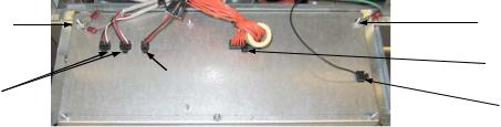
Ground Wire Terminal |
Ground Wire Terminal |
|
20-Pin Connector |
|
Drain Switch |
Communication Wires |
and LED |
|
Locator Wire |
5.Install the replacement controller. Reinstall the control panel assembly by reversing steps 1 thru 5.
6.Setup the controller following the instructions on page 1-3 in the FilterQuick™ Controller Operation manual. Setup MUST be performed prior to readdress.
7.Once setup is complete on all replaced controllers, CYCLE POWER TO ENTIRE FRYER SYSTEM. See section 1.15.6 to reset control power.
8.Check software version and if necessary update the software. If a software update was necessary, follow the instructions to update the software in section 1.19.
1.9.2Replacing the Temperature Probe, ATO Probe, AIF Probe, Oil Level Sensor or High-Limit Thermostat
1.Disconnect the fryer from the electrical supply.
2.Drain cooking oil below the level of the probe or thermostat.
3.Unscrew the filter push pull handle knobs.
4.Open the control panel by removing the screws on the bottom of the bezel. Carefully lower the bezel.
5.Remove the top two screws in the upper corners of the controller.
6.Swing the controller out from the top and allow it to rest on its hinge tabs.
7.Disconnect the controller wiring harness and ground wire from the back of the controller and remove the controller by lifting it from the hinge slots in the control panel frame.
8.Disconnect the ignition cables from the ignitors by grasping the boots and gently pulling toward you.
9.Disconnect the flame sensor wires from the flame sensors.
10.Disconnect the sound device lead from the interface board.
11.If working on the left frypot, cut the wire tie on the wiring bundle and disconnect the main wiring harness 15-pin connector.
12.Remove the component box mounting screws.
13.Rotate the top of the component box out of the frame and carefully pull it out enough to disconnect the wiring harness plug from the back of the box. This will leave one set of wires, enclosed in spiral wrap, connected to the component box.
14.Remove the box and set it atop the fryer to expose the temperature probe and high-limit thermostat.
15.Unscrew the probe or thermostat from the frypot.
16.Apply Loctite® PST56765 pipe thread sealant or equivalent to the replacement part threads and screw the replacement part into the frypot, torquing to 180 inch-pounds.
17.Connect the wires from the new component as follows:
a.If replacing a probe, use a pin pusher to disconnect (one at a time) the red and white leads from the connector and insert the corresponding leads from the new probe into the plug.
b.If replacing the high-limit thermostat, use a pin pusher to disconnect the lead running to the connector and insert the corresponding lead from the new thermostat.
c.Reverse steps 1 through 14 to complete the procedure.
1.9.3 Replacing the Interface Board
1.Perform steps 1 through 4 from section 1.9.1.
2.Disconnect the wires attached to the interface board, marking or making a note of the wires and terminals to facilitate reconnection.
3.Remove the nuts at each corner of the interface board and carefully pull it from the studs far enough to allow the connector on the back of the board to be disconnected, then remove the board from the box. When removing the board, be careful not to lose the spacers that fit over the studs behind the board.
4.Recover the relay(s) from the failed interface board and install on the replacement board.
1-7
5.Reverse the procedure to install the replacement board, being sure that the spacers behind the board are in place and the controller locator wire is attached to a stud.
1.9.4 Replacing an Ignition Module
1.Disconnect the fryer from the electrical supply.
2.Open the control panel by removing the screws on the bottom of the bezel. Carefully lower the bezel.
3.Remove the top two screws in the upper corners of the controller.
4.Swing the controller out from the top and allow it to rest on its hinge tabs.
5.Remove the two screws attaching the module cover.
6.Loosen the nuts attached to the screws of the module. Slide the module towards the rear of the component box until the nuts drop through the keyholes.
7.Carefully rotate the module and pull forward. On some units it may be necessary to remove the blower.
8.Disconnect the wires from the ignition module, marking or making a note of the wires and terminals to facilitate reconnection.
9.Remove the screws from the module.
10.Move the screws and spacers to the new module.
11.Reverse the procedure to install the replacement module.
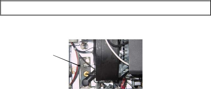
1.9.5 Replacing an Ignitor Assembly
 DANGER
Drain the frypot before proceeding further.
1.Disconnect the fryer from the electrical supply.
2.Disconnect the flame sensor wire by carefully pulling its push-on terminal from the terminal strip on the ignitor. Disconnect the gas enrichment tube at the ignitor-end compression fitting. Disconnect the ignition cable from the ignitor by grasping its boot and gently pulling toward you. (See photo on the next page)
Flame Sensor Wire
Gas Enrichment Tube 
Ignition Cable 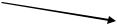
3.Remove the sheet metal screws securing the ignitor to the mounting plate and pull the ignitor from the fryer.
4.Reverse the procedure to install the replacement ignitor.
1.9.6 Replacing or Cleaning a Combustion Air Blower
1.Disconnect the blower wiring harness, remove the blower assembly mounting nuts, and remove the blower assembly from the fryer. If cleaning the motor, continue with Step 2; otherwise, install the replacement blower, reconnect the wiring harness, and then go to Step 6.
1-8
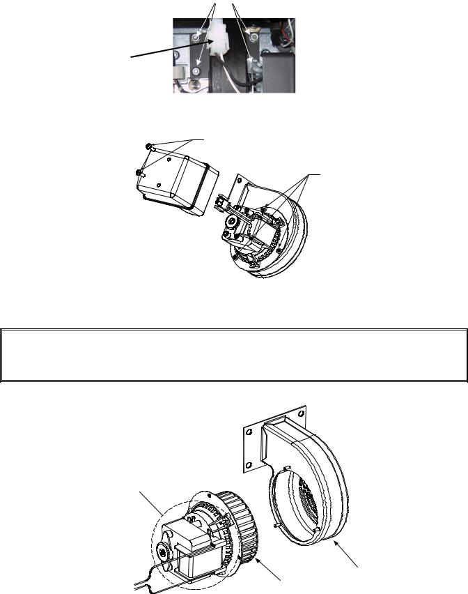
Blower assembly mounting nuts
Wiring connection
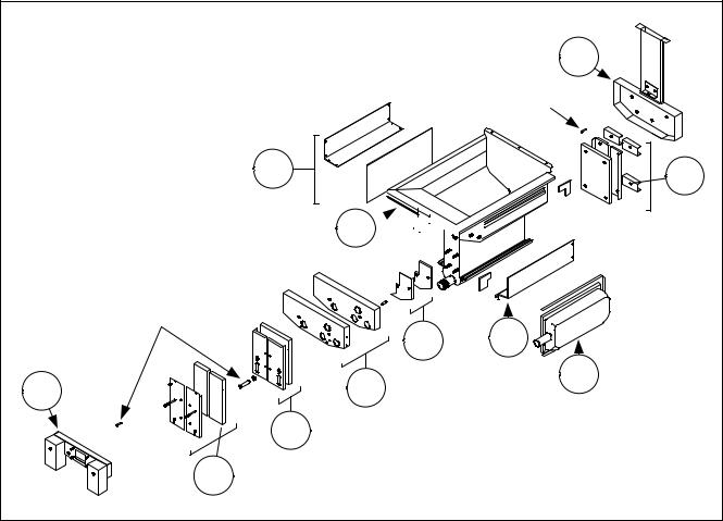
2.Remove the blower motor shield and separate the blower motor from the housing as shown in the illustration below.
Remove these screws to remove the shield from the blower assembly.
Remove these nuts to separate the blower motor from the housing.
3.Wrap the motor with plastic wrap to prevent water from entering it. Spray degreaser or detergent on the blower wheel and the blower housing. Allow it to soak for five minutes. Rinse the wheel and housing with hot tap water, then dry with a clean cloth.
NOTICEAustralia Only
The air pressure switch on the combustion blower should read: Full Vat units-122pa (0.5 inches W.C.) and for Split Vat units-180pa (0.72 inches W.C.).
Wrap the motor and wires with plastic wrap or a plastic bag.
Blower Housing
Blower Wheel
4.Remove the plastic wrap from the blower motor assembly. Reassemble the blower motor assembly and blower housing. Reinstall the blower shield.
1-9

5.Reinstall the blower assembly in the fryer and reconnect the wiring disconnected in Step 1.
6.Light the fryer in accordance with the procedure described in Chapter 3, Section 3.1.2 of the FilterQuick™ FQG30 Series Gas Fryer Installation and Operation Manual (P/N 819-6286).
7.After the burners have been lit for at least 90 seconds, observe the flames through the burner viewing ports located on each side of the combustion air blower.
|
Right |
Left Viewing |
Viewing Port is |
Port. |
behind motor. |
The air/gas mixture is properly adjusted when the burner manifold pressure is in accordance with the applicable table on page 1-5 and the burners display a bright orange-red glow. If a blue flame is observed or if there are dark spots on a burner face, the air/gas mixture requires adjustment.
NOTE: Opening the air shutter too much may result in whistling. It should not be more than 1/3 open.
1.9.7 Adjusting the Air/Gas Mixture
On the side of the blower housing opposite the motor is a shutter plate with a locking nut. Loosen the nut enough to allow the shutter to be moved, then adjust the position of the shutter to open or close the air intake opening until a bright orange-red glow is obtained, then close it slightly. Carefully hold the shutter in position and tighten the locking nut (see illustration on the following page).
On non-CE blowers loosen this nut and rotate shutter to open or close air intake.
On CE blowers loosen both
wing nuts and slide the
shutter to adjust the air
intake.
1.9.8 Replacing a Gas Valve
1.Disconnect fryer from electrical and gas supplies.
2.Disconnect the drain safety and high-limit thermostat wires from the gas valve. Mark each wire to facilitate reconnection.
3.Remove the vent tube (on non-CE fryers) and the enrichment tube fitting from the valve. Disconnect the flexible gas line(s).
If replacing the left-most valve on any configuration, or the right valve on a two-fryer battery, follow the instructions below. If replacing valves in other positions, skip to “ALL OTHER VALVES.”
A.Remove the filter pan from the unit. Remove the door adjacent to the valve being replaced.
B.Remove the screws on that attach the pan rails adjacent to the valve being replaced.
1-10

C.Uncouple the pipe union and remove the gas valve and associated piping from the unit.
D.Remove the fittings and associated piping from the failed valve and install them on the replacement valve using Loctite® PST56765 or equivalent pipe thread sealant.
E.Reconnect the gas valve assembly to the fryer using Loctite® PST56765 or equivalent pipe thread sealant, and reattach the flexible gas line(s), enrichment tube(s), and the vent tube (on non-CE units). Reconnect the high-limit thermostat wires and drain safety wires to the valve.
F.Reconnect the fryer to the gas supply and open the cut off valve. Apply a thick soapy solution of soapy water around each connection to check for gas leaks and ensure there are no bubbles. Eliminate any that are found. There should be no smell of gas.
G.Position the pan rail assembly beneath the fryer and rest the rear end of the rail on the cabinet frame. Install the two nuts and bolts behind the front face of the rail, but do not tighten them. Install the nut and bolt at the rear end of the filter rail and tighten securely.
H.Reattach the screws for the pan rails. Install the filter pan in the unit to make sure that all components are properly aligned.
I.Reconnect the fryer to the electrical power supply and check for proper operation. When proper operation has been verified, reinstall the door removed in Step A.
ALL OTHER VALVES
4.Carefully unscrew the valve from the manifold. NOTE: Some models may have the valve attached to the manifold by means of a pipe union. In such cases, remove the valve by uncoupling the union.
5.Remove all fittings from the old gas valve and install them on the replacement valve, using Loctite® PST56765 or equivalent pipe thread sealant.
6.Reconnect the gas valve assembly to the fryer using Loctite® PST56765 or equivalent pipe thread sealant, and reattach the flexible gas line(s), enrichment tube(s), and the vent tube (on non-CE units). Reconnect the high-limit thermostat wires and drain safety wires to the valve.
7.Reconnect the fryer to the gas supply and open the cut off valve. Apply a thick soapy solution of soapy water around each connection to check for gas leaks and ensure there are no bubbles. Eliminate any that are found. There should be no smell of gas.
8.Reconnect the fryer to the electrical power supply and check for proper operation.
1.9.9 Replacing a Burner Assembly
1.Disconnect the unit from the electrical and gas supplies.
2.Remove the gas line and enrichment tube using a 7/16” and 5/8” wrench from the front of the burner. It may be necessary to remove the MIB board in some locations.
3.Remove the elbow and tee off the bottom of the burner to ensure easier removal of the burner.
4.Remove the fryer back.
5.Remove the screws attaching the flue cap to the brace.
6.Remove the top cross brace in the back.
7.Remove the flue by removing the two screws in the rear and one screw in
the front of the flue. |
Figure 1 |
8.Remove all the screws on the flue collector and bend back the tabs and remove the collector.
9.Remove four screws on the collector insulation plate (see Figure 1).
10.Remove the four nuts and cover of the lower insulation retaining cover (see Figure 2).
11.Carefully remove the insulation being careful not to damage it.
12.Grasp the burner firmly and slide the burner out the rear of the fryer. Pull it toward you until it clears the burner channels, taking care not to damage the ceramic tiles in
the process.
13.Slide the burner out the rear of the fryer.
14.Clean all debris from the burner channels and combustion area.
15.Inspect the upper and lower burner rails for cracked or burned out welds.
1-11
Figure 2
Figure 3
a.If the welds in the lower rail are cracked or burned out, the frypot must be replaced. Refer to Section 1.9.11 for procedure.
b.If the welds in the upper rail are cracked or burned out, the upper rail must be replaced. Refer to Section 1.9.12 for procedure.
16.Wrap a new insulating strip along the top, rear, and bottom edge of the burner. NOTE: Use P/N 826-0931 for full-vat frypots and P/N 826-0932 for dual-vat frypots.
17.Carefully slide the replacement burner into the rails starting at the top and lifting slightly up on the bottom (see Figure 3). Ensure that the insulation is not torn or damaged.
18.In reverse order reassemble insulation and holding plates.
19.Install flue collector.
20.Install the flue.
21.Install the cross brace ensuring the flue cap is secured to the brace.
22.Replace the fryer back.
23.Reattach the elbow, gas line and enrichment tubes to the front of the burner.
24.Fill the frypot with oil. Turn the fryer on, turn off or bypass the melt cycle, and operate the unit for at least 10 minutes.
25.Visually examine the burner flame. The color and intensity on both sides should be the same.
26.Use an inspection mirror to check for leaks in areas that cannot be directly observed.
27.If a leak is detected, tighten all the lower insulation retainer nuts, allow the frypot to run for five additional minutes, and repeat steps 25 and 26.
28.If the leak persists, use a rubber hammer and a small block of wood to tap the corners of the lower combustion chamber insulation retainers. Repeat steps 25 through 27. Repeat this step until no leakage is detected.
1.9.10 Replacing the Filter Motor or Filter Pump
1.Disconnect the unit from the electrical power supply.
2.Remove the filter pan from the unit.
3.Position a container beneath the oil return fitting at the front of the cabinet. Disconnect the flexible oil line from the fitting, allowing any residual oil to drain into the container.
4.At the rear of the fryer, unplug the left connector (as viewed from the rear of the fryer) from the transformer box.
5.Remove the four nuts and bolts attaching the motor mount to the rear motor mount support.
6.At the front of the fryer, remove the cover plate from the front of the motor and disconnect the motor wires.
7.Place a 1-foot (30.5-cm) length of wood (or similar support) beneath the motor mount near the front of the unit and remove the two remaining nuts and bolts attaching the motor mount to the front cabinet crossbrace.
8.Carefully remove the support and lower the motor mount to the floor, allowing the rear of the mount to slide forward and off the rear motor mount support.
9.Disconnect the return flexline from the pump. The motor and pump assembly can now be pulled from beneath the fryer and the failed component can be removed and replaced.
10.Position the replacement motor and pump assembly beneath the fryer and reconnect the oil return flexline to the pump. Lift the rear of the motor mount up and onto the rear motor mount support.
11.Lift the front of the motor mount up and support it with a 1-foot (30.5-cm) piece of wood or a similar support. Install but do not tighten the two nuts and bolts that attach the motor mount to the front cabinet cross-brace.
12.Install and tighten the four nuts and bolts that secure the motor mount to the rear motor mount support.
13.At the front of the fryer, tighten the two nuts and bolts at the front of the motor mount. Reconnect the motor power wires and reinstall the wiring cover plate.
14.Reconnect the oil return flexline and reinstall the filter pan.
15.Reconnect the unit to the electrical power supply, fill the frypots with oil and check for proper operation.
1.9.11Replacing the Frypot
1. Disconnect the fryer from the electrical and gas supplies.
1-12

2.Remove the filter pan from the unit and drain one frypot at a time into a Shortening Disposal Unit (SDU) or other appropriate metal container using the drain function on the MIB board (see section 1.14 on page 29).
 DANGER
DO NOT attempt to drain more than one full frypot or two split frypots into the SDU at one time.
3.Dismount the topcap by removing the screws on the bottom of each front corner and lifting the topcap straight up.
4.Remove the bezels by lifting them up to disengage the tabs along the lower edges from the slots in the control panel frame. Remove the top screws in the upper corners of the controller.
5.Grasp the upper edge of each controller and swing the controller downward. Unplug the controller wiring harness and grounding wire from the back of each controller.
6.Remove the controllers by lifting them from the hinge slots in the control panel frame.
7.Disconnect the sound device wire from the interface board.
8.Disconnect the flame sensor wires by carefully pulling the push-on terminals from the terminal strips on the ignitors. Disconnect the gas enrichment tube at the ignitor-end compression fitting. Disconnect the ignition cables from the ignitors by grasping the boots and gently pulling toward you.
9.Remove the two mounting screws on each side of the component box and rotate the top of the box out of the frame. Carefully pull it out enough to disconnect the wiring harness connector from the back of the box. Cut any ties that prevent the box from being pulled out of the control panel frame.
10.Carefully pull the box clear of the frame and rest it on top of the fryer.
11.Using a pin pusher, remove the temperature probe, high-limit thermostat wires and RTD probe wires from the plugs or terminals, marking each wire to facilitate re-assembly.
12.Disconnect the actuators from the return and drain valves.
13.Remove the section(s) of drain from the drain valve(s) of the frypot to be removed.
14.Disconnect the gas lines from the burner orifices and ignitor assemblies.
15.Remove the frypot hold down bracket.
16.Remove the screws in the back panel and inside the flue cap at each end that secure the flue cap to the fryer and lift it clear of the fryer.
17.Disconnect the oil return line(s) from the frypot to be removed.
18.Disconnect all wiring from the AIF board.
19.Carefully lift the frypot from the fryer cabinet.
20.Remove the drain valve(s), temperature probe(s), high-limit thermostat(s), RTD probes, oil level sensor
probes, AIF boards, actuators and ignitor assemblies. Inspect each of these components carefully and install them in the replacement frypot if they are in serviceable condition. Use Loctite® PST56765 sealant or equivalent on component threads.
NOTE: Some servicers, based upon their experience, recommend that probes and thermostats be replaced whenever a frypot is replaced; however, this remains the customer’s decision.
21.Reverse steps 1-20 to reassemble fryer.
NOTE: Care should be taken not to over-torque nuts on frypots made of 400-series stainless steel, as this could tear the material. One turn past hand-tight is sufficient torque.
22.Perform steps 14 through 18 of Section 1.9.9 to ensure that there are no leaks in the burner insulation.
 CAUTION
Before installing temperature probes, high-limit thermostats, RTD probes, oil level sensor probes, return valves and drain valves on replacement frypot, clean the threads and apply Loctite® PST56765 thread sealant or equivalent.
1.9.12 Replacing Frypot Insulation and/or Upper Burner Rails
1-13
NOTE: Replacing the burner rails requires completely tearing down the frypot and installing new frypot insulation. Refer to the frypot exploded view below for component identification.
1.Remove the frypot per Section 1.9.11.
2.Remove the burner assemblies (1).
3.Remove insulation retainers and blanket insulation (2).
4.Remove the upper oil zone insulation bracket and upper oil zone insulation (3).
5.Remove the plenum (4).
6.Remove the front lower combustion chamber insulation retainer and insulation (5), and the front lower combustion chamber inner insulation retainer and insulation (6). NOTE: Full-vat units have two-piece insulation retainer and insulation components. Dual-vat units have one-piece components.
7.Remove the upper combustion chamber insulation retainer and insulation (7).
8.Remove the inner upper combustion chamber insulation retainer and insulation (8).
9.Remove the rear lower combustion chamber retainers, back, and insulation (9). NOTE: Full-vat units have two-piece backs and four retainers. Dual-vat units have one-piece backs and two retainers.
10.Remove the flue assembly (10).
10
Spacer
2 |
9 |
|
3 


|
Spacers |
11 |
|
8 |
|
4 |
7 |
1 |
|
||
|
6 |
|
5 Disassembling A Frypot
(Full Vat Illustrated)
See page 1-16 for reassembly illustration.
11.Remove the upper burner rails (11). NOTE: For the following steps, refer to the frypot exploded view on page 1-16 for component identification.
12.Remove any residual insulation, sealant, and/or oil from the exterior of the frypot.
13.Place the “L” shaped pieces of the combustion chamber insulation (1) in the front and rear corners of both upper rail-retaining slots. (See page 1-16).
14.Using a mallet and short piece of wood, tap the corner tabs of the combustion chamber over the insulation to ensure a solid seal of the burner.
15.Install the upper burner rails (2) with the heat deflectors slanting toward the rear of the frypot. The rails will cover the “L” shaped pieces of combustion chamber insulation previously installed.
1-14
16.Place the upper inner combustion chamber insulation and insulation retainers (3) on the top two studs on each side of the front of the frypot and secure with ¼”-20 washer-nuts. It is normal for the retainers to slice off the overhanging insulation.
17.Place the lower rear combustion chamber insulation (4) on the lower four studs at the rear of the frypot.
18.Place one 1.625-inch tubular spacer (5) on each of the flue assembly (upper) studs at the rear of the frypot. NOTE: There are three different sizes of spacers. Verify the size to ensure the correct spacers are installed.
19.Press the flue assembly (6) over the burner rails. It may be necessary to use a rubber mallet or screwdriver to align the components. Use four ¼”-20 washer nuts to secure the flue assembly. Do not tighten the retainer nuts at this point. They should be finger-tight only. NOTE: The flue edge will cover one to two inches of the lower insulation.
20.Install the lower rear combustion chamber back(s) and retainer(s) (7) with the flanged edge(s) against the flue. Secure with ¼”-20 washer nuts. NOTE: Full-vat units have two-piece backs and four retainers. Dual-vat units come with one-piece backs and only two retainers.
21.Insert the burners (9) into the rails to ensure the rail spacing and alignments are correct. The burner should slide freely into and out of the rails. The upper rail can be bent slightly to increase or decrease tension on the burner and the edges of the slot can be closed or opened slightly to best fit the burner frame.
22.Carefully wrap a strip of burner insulation (8) tightly around the rear and sides of the burner frame (9), with the glass-tape side of the strip on the outside. Do not use duct tape or adhesive to secure the strip to the burner frame.
23.Align the burner to the burner rails while maintaining tension on the insulation strip. Insert the burner at a slight angle and begin pushing the burner slowly into the rails until it contacts the rear combustion chamber. The fit should be snug, but not excessively tight.
24.Verify that the burners are flush with the front edge of the burner rails. Remove the excess burner insulation by cutting with a knife or diagonal pliers. Do not try to tear the insulation!
25.Insert the upper front insulation (10) into its retainer (11), making sure that the holes in each piece are aligned with one another. Install the assembly with the insulation side toward the frypot and secure with ¼”-20 washer-nuts. Do not over tighten.
26.Place a washer on each of the four lower studs on the front of the frypot. Install the lower inner front insulation (12) with the rectangular openings toward the drain valve nipple. Install the lower inner front insulation retainer(s) (13). NOTE: Full-vat units have a two-piece insulation retainer. Dual-vat units have a one-piece retainer.
27.If necessary, replace the sight-glasses and insulation (14).
28.Place one washer and one 1.888-inch spacer (15) on each stud. NOTE: There are three different sizes of spacers. Verify the size to ensure the correct spacers are installed.
29.Insert the front lower insulation (16) into the front lower insulation retainer(s) (17) and install assembly on frypot. Secure with ¼”-20 washer-nuts. If frypot uses two retainers, connect them together with two ¼” self-tapping screws. NOTE: Full-vat units have a two-piece insulation retainer and two pieces of insulation. Dual-vat units have one-piece components.
30.Return to the rear of the frypot and fully tighten all washer-nuts.
31.Remove and replace the plenum gaskets (18).
32.Place a 0.938-inch spacer (19) on the plenum-mounting studs, and mount the plenum (20). Ensure the gaskets are clear of the burner tubes by pulling the plenum back slightly. Place a washer on each stud and secure plenum with ¼”-20 lock-nuts.
33.Install the upper oil-zone insulation (21) by pressing it under the upper combustion chamber metalwork. Secure the insulation with the bracket (22) and ¼” self-tapping screws.
34.Install the upper burner rail blanket insulation (23). Position any excess insulation toward the top of the frypot. Avoid overhang past the bottom of the upper burner rail. Overhang in this area will make future burner replacement more difficult.
35.Cover the insulation with the insulation retainer (24), and secure with ¼” self-tapping screws.
36.Reinstall probes, drain valves, AIF boards, actuators, high-limit thermostats, and other pipe fittings using Loctite® PST56765 sealant or equivalent on the threads.
1-15
|
|
|
|
6 |
|
|
|
|
|
5 |
|
|
|
24 |
|
4 |
|
|
|
23 |
|
|
|
|
|
|
21 |
1 |
7 |
|
|
|
22 |
2 |
|
|
|
|
|
||
|
|
|
|
|
|
|
|
|
|
|
8 |
|
|
16 |
1 |
|
|
|
17 |
3 |
|
9 |
|
|
15 |
|
|||
|
|
|
10 |
|
|
20 |
19 |
12 |
11 |
|
|
|
|
|
|
|
|
|
|
13 |
|
|
|
|
|
14 |
|
|
|
|
18 |
Re-assembling A Frypot |
|
|
|
|
|
(Full-Vat Illustrated) |
|
|
|
1.10 Troubleshooting and Problem Isolation |
|
|
|||
Because it is not feasible to attempt to include in this manual every conceivable problem or trouble condition that might be encountered, this section is intended to provide technicians with a general knowledge of the broad problem categories associated with this equipment, and the probable causes of each. With this knowledge, the technician should be able to isolate and correct any problem encountered.
Problems you are likely to encounter can be grouped into six categories:
1.Ignition failure
2.Improper burner function
3.Improper temperature control
4.Controller malfunctions
5.Filtration malfunctions
6.Leakage
The probable causes of each category are discussed in the following sections. A series of Troubleshooting Guides is also included at the end of the chapter to assist in solving some of the more common problems.
1.10.1Heating (Ignition) Failure
Heating (ignition) failure occurs when the ignition module fails to sense a flame within the 4-second time delay period and locks out. When this happens, the module sends 24 VAC through the interface board alarm circuit to the controller.
FilterQuick™ controllers display “HEATING FAILURE.”
The three primary reasons for heating failure, listed in order of probability, are problems related to:
1-16
1.Gas and/or electrical power supplies
2.Electronic circuits
3.Gas valve.
PROBLEMS RELATED TO THE GAS AND/OR ELECTRICAL POWER SUPPLIES
The main indicators of this are that an entire battery of fryers fails to light and/or there are no indicator lights illuminated on the fryer experiencing heating failure. Verify that the quick disconnect fitting is properly connected, the fryer is plugged in with connector twisted and locked, the main gas supply valve is open, and the circuit breaker for the fryer electrical supply is not tripped.
PROBLEMS RELATED TO THE ELECTRONIC CIRCUITS
If gas and electrical power are being supplied to the fryer, the next most likely cause of heating failure is a problem in the 24 VAC circuit. Verify that the oil level sensor is working properly. Refer to Section 1.11.1,
TROUBLESHOOTING THE 24 VAC CIRCUIT.
Some typical causes of heating failure in this category include a defective sensing wire in the ignitor assembly, a defective module, a defective ignition wire, and a defective ignitor.
Occasionally, a heating failure situation occurs in which all components appear to be serviceable and the microamp reading is within specification, but the unit nevertheless goes into heating failure during operation. The probable cause in this case is an intermittent failure of an ignition module. When the unit is opened up for troubleshooting, the module cools down enough to operate correctly; however, when the unit is again closed up
and placed back into service the module heats up and fails.
PROBLEMS RELATED TO THE GAS VALVE
If the problem is not in the 24 VAC circuit, it is most likely in the gas valve, itself. Before replacing the gas valve, refer to Section 1.11.2 TROUBLESHOOTING THE GAS VALVE.
1.10.2 Improper Burner Function
With problems in this category, the burner ignites but exhibits abnormal characteristics such as “popping,” dark spots on the burner ceramics, fluctuating flame intensity, and flames shooting out of the flue.
“Popping” indicates delayed ignition. In this condition, the main gas valve is opening but the burner is not immediately lighting. When ignition does take place, the excess gas “explodes” into flame, rather than smoothly igniting.
The primary causes of popping are:
Incorrect or fluctuating gas pressure
Defective or incorrectly adjusted combustion air blower
Inadequate make-up air
Heat-damaged controller or ignition module
Cracked ignitor or broken ignition wire
Defective ignition module
Cracked burner tile (typically causes a very loud pop).
If popping occurs only during peak operating hours, the problem may be incorrect or fluctuating gas pressure. Verify that the incoming gas pressure (pressure to the gas valve) is in accordance with the appropriate CE or Non-CE Standard found in Section 2.3 page 2-4 of the FilterQuick™ FQG30 Series Gas Fryer Installation and Operation Manual (PN 819-7052), and that the pressure remains constant throughout all hours of usage. Refer to Section 1.7, Checking the Burner Manifold Gas Pressure in this manual for the procedure for checking the pressure of gas supplied to the burner.
1-17
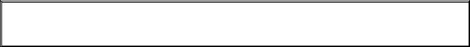
If popping is consistent during all hours of operation, the most likely cause is an insufficient air supply. Check for “negative pressure” conditions in the kitchen area. If air is flowing into the kitchen area, this indicates that more air is being exhausted than is being replenished and the burners may be starved for air.
If the fryer’s gas and air supplies are correct, the problem is most likely with one of the electrical components. Examine the ignition module and controller for signs of melting, distortion, and/or discoloration due to excessive heat build-up in the fryer (this condition usually indicates improper flue performance). A melted or distorted ignition module is automatically suspect and should be replaced; however, unless the condition causing excessive heat is corrected, the problem is likely to recur.
Verify that the ignition wire is tightly connected at both ends and free of obvious signs of damage. Again, if damage is due to excessive heat in the fryer, that problem must also be corrected. Check for proper operation by disconnecting the wire from the ignitor (spark plug), inserting the tip of a screw driver into the terminal. With the insulated handle of the screwdriver, hold the shaft near the frame of the fryer as the power switch is placed in the ON position. A strong, blue spark should be generated for at least four seconds.
 DANGER
Make sure you are holding the insulated handle of the screwdriver and not the blade. The sparking charge is approximately 25,000 volts.
Examine the ignitor (spark plug) for any signs of cracking. A cracked ignitor must be replaced.
If all other causes have been ruled out, examine the burner tiles for any signs of cracking. If cracking is found, the burner must be replaced.
Fluctuating flame intensity is normally caused by either improper or fluctuating incoming gas pressure, but may also be the result of variations in the kitchen atmosphere. Verify incoming gas pressure in the same way as for “popping,” discussed in the preceding paragraphs. Variations in the kitchen atmosphere are usually caused by air conditioning and/or ventilation units starting and stopping during the day. As they start and stop, the pressure in the kitchen may change from positive or neutral to negative, or vice versa. They may also cause changes in airflow patterns that may affect flame intensity.
Dark spots on the burner tiles are the result of an improper air/gas mixture. Adjust the combustion air blower to reduce the amount of air in the mixture to correct this problem.
Flames shooting out of the flue are usually an indication of negative pressure in the kitchen. Air is being sucked out of the burner enclosure and the flames are literally following the air. If negative pressure is not the cause, check for high burner manifold gas pressure in accordance with the procedures in Section 1.7.
An excessively noisy burner, especially with flames visible above the flue opening, may indicate that the gas pressure is too high, or it may simply be that the gas valve vent tube is blocked. If the incoming gas pressure is correct and the vent tube is unobstructed, the gas valve regulator is probably defective.
Occasionally a burner may apparently be operating correctly, but nevertheless the fryer has a slow recovery rate (the length of time required for the fryer to increase the oil temperature from 250ºF to 300ºF (121ºC to 149ºC)). The primary causes of this include an over-filled frypot, a dirty or out-of-adjustment combustion air blower, low burner manifold pressure, and/or damaged burner tiles. Adding oil to the frypot during the recovery process will also cause a slow recovery rate.
If these causes are ruled out, the probable cause is a misadjusted gas valve regulator. Refer to Section 1.7, Checking the Burner Manifold Gas Pressure, for the gas valve adjustment procedure.
1.10.3 Improper Temperature Control
Temperature control, including the melt cycle, is a function of several interrelated components, each of which must operate correctly. The principle component is the temperature probe. Other components include the interface board, the controller itself, and the ignition module.
Improper temperature control problems can be categorized into melt cycle problems and failure to control at setpoint problems.
MELT CYCLE PROBLEMS
1-18
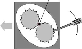
Initiation of the melt cycle with FilterQuick™ controllers is automatic. Problems may originate from the controller itself, the temperature probe, or a malfunctioning heat relay on the interface board.
FAILURE TO CONTROL AT SETPOINT
Problems in this category may be caused by the temperature probe, the interface board, or the controller.
1.10.4 Controller Malfunctions
RECOVERY TIME
Recovery time – is a method of measuring a fryer’s performance. Put simply, it is the time required for the fryer to increase the oil temperature from 250ºF to 300ºF (121ºC to 149ºC). This range is used as a standard since ambient kitchen temperatures can affect the test if lower ranges are used.
The FilterQuick™ controller performs the recovery test each time the fryer warms up. An operator can view the results of the test any time the fryer is above the 300ºF (149ºC) point by pressing the check button once when the fryer is on. The test results will be displayed in the controller’s LED panel in minutes and seconds. The maximum acceptable recovery time for FilterQuick™ FQG30 Series gas fryers is two minutes and twenty-five seconds.
1.10.5Filtration Malfunctions
The majority of filtration problems arise from operator error. One of the most common errors is placing the filter paper/pad on the bottom of the filter pan rather than over the filter screen.
Whenever the complaint is “the pump is running, but no oil is being filtered,” check the installation of the filter paper/pad, including that the correct size is being used. While you are checking the filter paper/pad, verify that the O-rings on the filter pan suction tube are present and in good condition. Missing or worn O-rings will allow the pump to suck air and decrease its efficiency.
If the pump motor overheats, its thermal overload will trip and the motor will not start until it is reset. If the pump motor does not start, press the red reset switch located on the front of the motor. If the pump then starts, something caused the motor to overheat. It may be just that several frypots in a
large battery of fryers were being filtered one after the other and the |
|
|
PUMP |
||||
pump became hot. Letting the pump cool down for at least a half-hour |
|
|
|
|
Sediment |
||
is all that is required in this case. More often, the pump overheated for |
|
|
|
|
Particle |
||
|
|
|
|
|
|
|
|
one of the following reasons: |
|
|
|
|
|
|
Up for |
|
|
|
|
|
|
||
|
|
|
|
|
|
reverse |
|
|
|
|
|
|
|
|
|
Shortening that remained in the pan after previous filtering |
|
|
|
|
|
|
|
solidified in the suction tube recess in the bottom of the pan or |
|
|
|
|
|
|
|
the suction tube, itself. Adding hot oil to the pan and waiting |
|
|
|
|
|
|
|
a few minutes will usually correct this problem. A flexible |
FLOW |
|
|
|
|
|
|
|
|
|
|
|
|
|
|
wire can be used to clean out the suction tube and the recess in |
|
|
|
|
|
|
|
|
|
|
|
|
|
|
|
the bottom of the pan. NEVER use compressed air to blow |
|
|
|
|
|
|
Down for |
|
|
|
|
|
|
forward |
|
solidified shortening out of the suction tube! |
|
|
|
|
|
|
|
The operator attempted to filter oil that was not heated. Cold oil is thicker and causes the pump motor to work harder and
overheat.
If the motor hums but the pump does not rotate, there is a blockage in the pump. Incorrectly sized or installed paper will allow food particles and sediment to pass through the filter pan and into the pump. When sediment enters the pump, the gears can bind up and cause the motor to overload, tripping the thermal overload. Solidified shortening in the pump will also cause it to seize, with similar results.
A pump seized by debris or hard shortening can usually be freed by manually moving the gears with a screwdriver or other instrument as illustrated on the following page. Make sure power to the pump motor is off before trying this.
1.Disconnect power to the filter system.
2.Remove the input plumbing from the pump.
3.Use a screwdriver to manually turn the gears.
1-19
 Loading...