


BIELA14 Series
Gen II LOV™ Electric Fryer
Parts Manual
This manual is updated as new information and models are released. Visit our website for the latest manual. This equipment chapter is to be installed in the Fryer Section of the Equipment Manual.
FOR YOUR SAFETY
Do Not Store or use gasoline or other flammable vapors and liquids in the vicinity of this or any other appliance.
*8197260*
Part Number: FRY_P_8197260 07/2017
NOTICE
IF, DURING THE WARRANTY PERIOD, THE CUSTOMER USES A PART FOR THIS FRYMASTER EQUIPMENT OTHER THAN AN UNMODIFIED NEW OR RECYCLED PART PURCHASED DIRECTLY FROM FRYMASTER DEAN, OR ANY OF ITS FACTORY AUTHORIZED SERVICERS, AND/OR THE PART BEING USED IS MODIFIED FROM ITS ORIGINAL CONFIGURATION, THIS WARRANTY WILL BE VOID. FURTHER, FRYMASTER DEAN AND ITS AFFILIATES WILL NOT BE LIABLE FOR ANY CLAIMS, DAMAGES OR EXPENSES INCURRED BY THE CUSTOMER WHICH ARISE DIRECTLY OR INDIRECTLY, IN WHOLE OR IN PART, DUE TO THE INSTALLATION OF ANY MODIFIED PART AND/OR PART RECEIVED FROM AN UNAUTHORIZED SERVICER.
NOTICE
This appliance is intended for professional use only and is to be operated by qualified personnel only. A Frymaster Authorized Servicer (FAS) or other qualified professional should perform installation, maintenance, and repairs. Installation, maintenance, or repairs by unqualified personnel may void the manufacturer’s warranty. See Chapter 1 of this manual for definitions of qualified personnel.
NOTICE
This equipment must be installed in accordance with the appropriate national and local codes of the country and/or region in which the appliance is installed. See NATIONAL CODE REQUIREMENTS in Chapter 2 of this manual for specifics.
NOTICE TO U.S. CUSTOMERS
This equipment is to be installed in compliance with the basic plumbing code of the Building Officials and Code Administrators International, Inc. (BOCA) and the Food Service Sanitation Manual of the U.S. Food and Drug Administration.
NOTICE
This appliance is intended to be used for commercial applications, for example in kitchens of restaurants, canteens, hospitals and in commercial enterprises such as bakeries, butcheries, etc., but not for continuous mass production of food.
NOTICE
Drawings and photos used in this manual are intended to illustrate operational, cleaning and technical procedures and may not conform to onsite management operational procedures.
NOTICE TO OWNERS OF UNITS EQUIPPED WITH COMPUTERS
U.S.
This device complies with Part 15 of the FCC rules. Operation is subject to the following two conditions: 1) This device may not cause harmful interference, and 2) This device must accept any interference received, including interference that may cause undesired operation. While this device is a verified Class A device, it has been shown to meet the Class B limits.
CANADA
This digital apparatus does not exceed the Class A or B limits for radio noise emissions as set out by the ICES 003 standard of the Canadian Department of Communications.
Cet appareil numerique n’emet pas de bruits radioelectriques depassany les limites de classe A et B prescrites dans la norme NMB 003 edictee par le Ministre des Communcations du Canada.

 DANGER
Improper installation, adjustment, maintenance or service, and unauthorized alterations or modifications can cause property damage, injury, or death. Read the installation, operating, and service instructions thoroughly before installing or servicing this equipment.
NOTICE
The appliance must be installed and used in such a way that any water cannot contact the fat or oil.
 DANGER
The front ledge of this appliance is not a step! Do not stand on the appliance. Serious injury can result from slips or contact with the hot oil.
 DANGER
Do not store or use gasoline or other flammable liquids or vapors in the vicinity of this or any other appliance.
 DANGER
The crumb tray in fryers equipped with a filter system must be emptied into a fireproof container at the end of frying operations each day. Some food particles can spontaneously combust if left soaking in certain shortening material.
 WARNING
Do not bang fry baskets or other utensils on the fryer’s joiner strip. The strip is present to seal the joint between the fry vessels. Banging fry baskets on the strip to dislodge shortening will distort the strip, adversely affecting its fit. It is designed for a tight fit and should only be removed for cleaning.
 DANGER
Adequate means must be provided to limit the movement of this appliance without depending on or transmitting stress to the electrical conduit. A restraint kit is provided with the fryer. If the restraint kit is missing contact your local KES.
 DANGER
This fryer has a power cord (three phase) for each frypot and a single five wire cord for the entire system. Prior to movement, testing, maintenance and any repair on your Frymaster fryer; disconnect ALL electrical power cords from the electrical power supply.
 DANGER
Keep all items out of drains. Closing actuators may cause damage or injury.
NOTICE
The instructions in this manual for using a bulk oil system for filling and discarding oil are for an RTI system. These instructions may not be applicable to other bulk oil systems.
LOV™ ELECTRIC WARRANTY STATEMENT
Frymaster, L.L.C. makes the following limited warranties to the original purchaser only for this equipment and replacement parts:
A.WARRANTY PROVISIONS - FRYERS
1.Frymaster L.L.C. warrants all components against defects in material and workmanship for a period of two years.
2.All parts, with the exception of the frypot, O-rings and fuses, are warranted for two years after installation date of fryer.
3.If any parts, except fuses and filter O-rings, become defective during the first two years after installation date, Frymaster will also pay straight-time labor costs up to two hours to replace the part, plus up to 100 miles/160 km of travel (50 miles/80 km each way).
B.WARRANTY PROVISIONS - FRYPOTS
The frypot has a lifetime parts and labor warranty. If a frypot develops a leak after installation, Frymaster will replace the frypot, allowing up to the maximum time per the Frymaster time allowance chart hours of straight-time labor. Components attached to the frypot, such as the high-limit, probe, gaskets, seals, and related fasteners, are also covered by the lifetime warranty if replacement is necessitated by the frypot replacement. Leaks due to abuse or from threaded fittings such as probes, sensors, high-limits, drain valves or return piping are not included.
C. PARTS RETURN
All defective in-warranty parts must be returned to a Frymaster Authorized Factory Service Center within 60 days for credit. After 60 days, no credit will be allowed.
D. WARRANTY EXCLUSIONS
This warranty does not cover equipment that has been damaged due to misuse, abuse, alteration, or accident such as:
improper or unauthorized repair (including any frypot which is welded in the field);
failure to follow proper installation instructions and/or scheduled maintenance procedures as prescribed in your MRC cards. Proof of scheduled maintenance is required to maintain the warranty;
improper maintenance;
damage in shipment;
abnormal use;
removal, alteration, or obliteration of either the rating plate or the date code on the heating elements;
ii
operating the frypot without shortening or other liquid in the frypot;
no fryer will be warranted under the ten-year program for which a proper start-up form has not been received.
This warranty also does not cover:
transportation or travel over 100 miles/160 km (50 miles/80 km each way), or travel over two hours;
overtime or holiday charges;
consequential damages (the cost of repairing or replacing other property which is damaged), loss of time, profits, use or any other incidental damages of any kind.
There are no implied warranties of merchantability or fitness for any particular use or purpose. This warranty is applicable at the time of this printing and is subject to change.
ELECTRICAL POWER SPECIFICATIONS
|
|
WIRE |
MIN. |
AWG |
|
AMPS PER LEG |
|
||
VOLTAGE |
PHASE |
SERVICE |
SIZE |
(mm2) |
L1 |
|
L2 |
|
L3 |
208 |
3 |
3 |
6 |
(16) |
39 |
|
39 |
|
39 |
|
|
|
|
|
|
|
|
|
|
240 |
3 |
3 |
6 |
(16) |
34 |
|
34 |
|
34 |
|
|
|
|
|
|
|
|
|
|
480 |
3 |
3 |
8 |
(10) |
17 |
|
17 |
|
17 |
|
|
|
|
|
|
|
|
|
|
220/380 |
3 |
4 |
6 |
(16) |
21 |
|
21 |
|
21 |
|
|
|
|
|
|
|
|
|
|
240/415 |
3 |
4 |
6 |
(16) |
20 |
|
20 |
|
21 |
|
|
|
|
|
|
|
|
|
|
230/400 |
3 |
4 |
6 |
(16) |
21 |
|
21 |
|
21 |
|
|
|
|
|
|
|
|
|
|
iii

BIELA14 SERIES GEN II LOV™ ELECTRIC FRYERS
PARTS
TABLE OF CONTENTS
CAUTIONARY STATEMENTS............................................................................................................................................................................ |
|
i |
||
WARRANTY STATEMENT................................................................................................................................................................................ |
|
ii |
||
ELECTRICAL POWER SPECIFICATIONS .................................................................................................................................................... |
iii |
|||
CHAPTER 1: Parts List |
|
|
||
1.1 |
Accessories ................................................................................................................................................................................. |
|
1-1 |
|
1.2 |
Doors, Sides, Tilt Housings, Cap N Splash, Top Caps and Casters............................................................................ |
1-2 |
||
1.3 |
Drain System Components ................................................................................................................................................... |
1-3 |
||
|
1.3.1 |
Drain Tube Sections and Associated Parts ................................................................................................. |
1-3 |
|
|
1.3.2 |
Drain Valves and Associated Parts ................................................................................................................ |
1-4 |
|
1.4 |
Electronics and Electrical Components ............................................................................................................................ |
1-5 |
||
|
1.4.1 |
Component Boxes .............................................................................................................................................. |
1-5 |
|
|
1.4.2 |
Contactor Boxes .................................................................................................................................................. |
1-7 |
|
|
1.4.3 |
Heating Element Assemblies and Associated Parts ................................................................................ |
1-9 |
|
|
|
1.4.3.1 Element Assemblies and Hardware ............................................................................................ |
1-9 |
|
|
|
1.4.3.2 |
Element Tube Assemblies ............................................................................................................ |
1-11 |
|
1.4.4 |
Computers........................................................................................................................................................... |
1-12 |
|
|
1.4.5 |
Wiring.................................................................................................................................................................... |
|
1-13 |
|
|
1.4.5.1 Contactor Box Wiring Assemblies 12-Pin Dual Vat .............................................................. |
1-13 |
|
|
|
1.4.5.2 Contactor Box Wiring Assemblies 12-Pin Full Vat ................................................................ |
1-13 |
|
|
|
1.4.5.3 Contactor Box Wiring Assemblies 6-Pin Left Element ........................................................ |
1-14 |
|
|
|
1.4.5.4 Contactor Box Wiring Assemblies 9-Pin Right Element ..................................................... |
1-14 |
|
|
|
1.4.5.5 |
Main Wiring Harnesses.................................................................................................................. |
1-15 |
|
|
1.4.5.6 Component Box and Filter Pump Wiring Harnesses........................................................... |
1-16 |
|
|
|
1.4.5.7 Interface Board to Controller Wiring Harness 15-Pin .......................................................... |
1-16 |
|
|
|
1.4.5.8 M3000, MIB, AIF and ATO Wiring Harnesses .......................................................................... |
1-17 |
|
1.5 |
Filtration System Components .......................................................................................................................................... |
1-18 |
||
|
1.5.1 |
Filtration Components ........................................................................................................................................ |
1-18 |
|
|
1.5.2 |
Auto Intermittent Filtration Components .................................................................................................... |
1-20 |
|
|
|
1.5.2.1 LOV Indicator Lights Assembly................................................................................................... |
1-20 |
|
|
|
1.5.2.2 Manual Interface Board Assembly............................................................................................. |
1-20 |
|
|
|
1.5.2.3 AIF Linear Actuator Board Assembly ........................................................................................ |
1-21 |
|
|
|
1.5.2.4 LOV PCB Board Matrix.................................................................................................................... |
1-21 |
|
1.6 |
Frypot Assemblies and Associated Components........................................................................................................ |
1-22 |
||
1.7 |
Oil Return Manifolds.............................................................................................................................................................. |
1-24 |
||
1.8 |
Return Valves and Associated Parts ................................................................................................................................. |
1-24 |
||
1.9 |
Auto Top Off Components.................................................................................................................................................. |
1-25 |
||
|
1.9.1 |
JIB Basket ................................................................................................................................................................. |
|
1-25 |
|
1.9.2 |
JIB Cap and Pick Up Assembly.......................................................................................................................... |
1-25 |
|
|
1.9.3 |
Automatic Top Off Board Assembly ............................................................................................................... |
1-26 |
|
|
1.9.4 |
ATO Pump Assembly ........................................................................................................................................... |
1-27 |
|
|
1.9.5 |
ATO Pump Assembly Service Kit (Larger Top Off Lines) .......................................................................... |
1-28 |
|
|
1.9.6 |
Shrotening Melting Unit..................................................................................................................................... |
1-29 |
|
1.10 |
RTI.................................................................................................................................................................................................. |
|
|
1-30 |
|
1.10.1 RTI Manifold and Accessories ........................................................................................................................... |
1-30 |
||
|
1.10.2 RTI Dispose Waste Valve..................................................................................................................................... |
1-32 |
||
|
1.10.3 |
RTI test Box.............................................................................................................................................................. |
1-32 |
|
1.11 |
Wiring Connectors, Pin Terminals and Power Cords.................................................................................................. |
1-33 |
||
1.12 |
Fasteners ................................................................................................................................................................................... |
|
1-34 |
|
1.13 |
Oil Quality Sensor (OQS) and Associated Parts ............................................................................................................ |
1-35 |
||
iv
BIELA14 SERIES GEN II LOV™ ELECTRIC FRYERS
CHAPTER 1: PARTS LIST
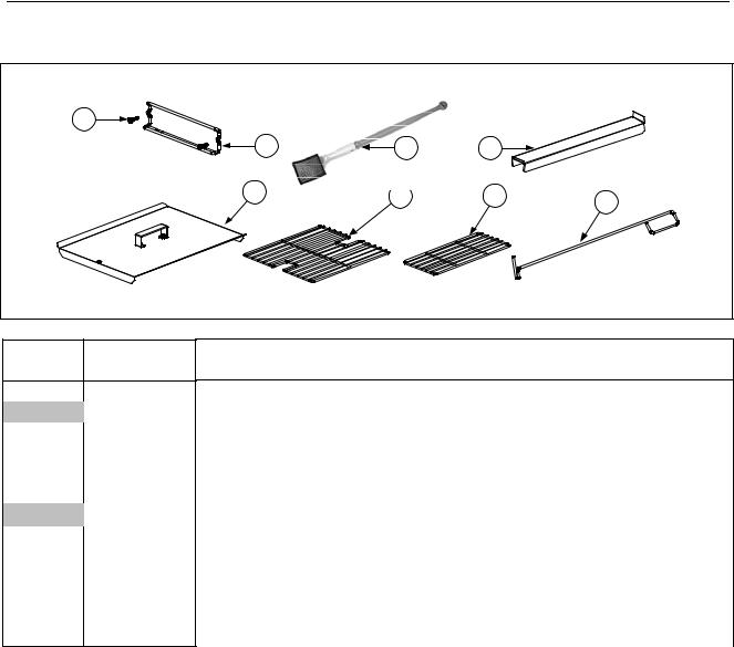
1.1 |
Accessories |
|
|
ITEM |
PART # |
COMPONENT |
|
|
1 |
8090171 |
Thumbscrew, ¼ -20 X 1⅜-inch Universal Hood |
|
|
8090402 |
Thumbscrew, ¼ -20 X ½-inch Cap-N-Splash Hood |
|
2 |
8102793 |
Hanger, Wireform Basket |
|
* |
8090921 |
Spacer, Basket Hanger |
|
3 |
8030430 |
Brush, Frypot Ecolab |
|
4 |
8237263 |
Connecting Strip, Frypot prior to 07/2014 |
|
|
8238963 |
Connecting Strip, Frypot after 06/2014 |
|
5 |
1068325 |
Cover, Full-Vat Frypot |
*1068329 Cover, Dual-Vat Frypot
*8260993SP Handle Kit, Frypot Cover (includes handle and screws)
68030132 Rack, Full-Vat Basket Support
78030106 Rack, Dual-Vat Basket Support
8 |
8030388 |
Element Lift / Fryers Friend LOV™ |
*Not illustrated.
1-1
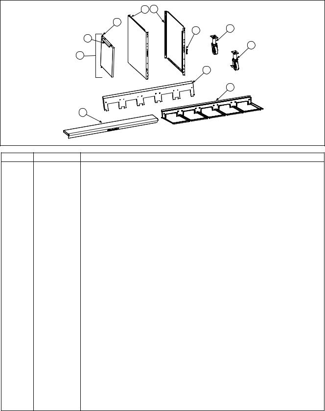
1.2 Doors, Sides, Tilt Housings, Cap-N-Splash, Top Caps and Casters
ITEM |
PART # |
COMPONENT |
12310323 Side, Standard Cabinet Left SS (use 2210323 for Enameled Steel)
22320323 Side, Standard Cabinet Right SS (use 2220323 for Enameled Steel)
38101105 Magnet, Door (vertical) (use 8102346 for horizontal over filter pan)
41080915 Door, Left or Right (Left shown – move handle to bottom for right)
5 |
2304960 |
Handle, Eurolook Door |
61064067SP Pin Assembly, Door
* |
8100275 |
Spring, Door Pin |
* |
8090970 |
Retaining Ring |
* |
2307192 |
Hinge, Door Lower |
* |
2206097 |
Holder, Manual |
78100327 Caster without Brake
88100326 Caster with Brake
9 Tilt Housing (Housing for five station fryer shown)
|
8236085 |
Two Station, S/S (use 1080131 for Aluminized Steel) (9102441 Hoodstrip) |
|
8235700 |
Three Station, S/S (use 1080132 for Aluminized Steel) (9102440 Hoodstrip) |
|
8236151 |
Four Station, S/S (use 1080133 for Aluminized Steel) (9102439 Hoodstrip) |
|
8236243 |
Five Station, S/S (use 1080138) for Aluminized Steel) (9109447 Hoodstrip) |
10 |
|
Cap-N-Splash |
|
8236420 |
Two Station |
|
8236421 |
Three Station |
|
8236422 |
Four Station |
|
8236887 |
Five Station |
11 |
|
Top Cap (Top cap for five station fryer shown) |
|
1067835 |
Two Station (Req 4- 8090078 10-32 Nutserts) prior to 07/2014 |
|
1086162SP |
Two Station (Req 4- 8090078 10-32 Nutserts) after 06/2014 |
|
1065979 |
Three Station (Req 6-8090078 10-32 Nutserts) prior to 07/2014 |
|
1086163SP |
Three Station (Req 6-8090078 10-32 Nutserts) after 06/2014 |
|
1067576 |
Four Station (Req 8- 8090078 10-32 Nutserts) prior to 07/2014 |
|
1086164 |
Four Station (Req 8- 8090078 10-32 Nutserts) after 06/2014 |
|
1067841 |
Five Station (Req10-8090078 10-32 Nutserts) prior to 07/2014 |
|
1086165 |
Five Station (Req10-8090078 10-32 Nutserts) after 06/2014 |
* Not illustrated.
1-2
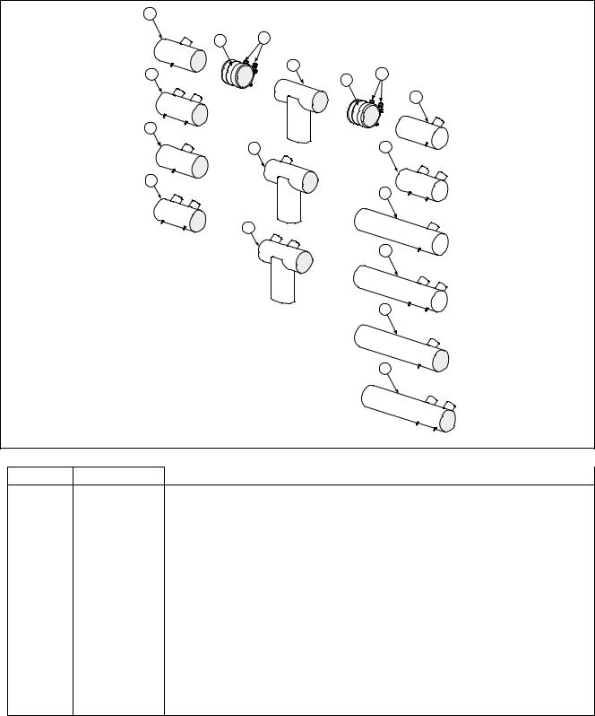
1.3Drain System Components
1.3.1 Drain Tube Sections and Associated Parts
See Section 1.3.2 for Drain Valves
ITEM |
PART# |
COMPONENT |
18236020 Drain Tube, Full-Vat Left Closed/Right End Open
28236112 Drain Tube, Dual-Vat Left Closed/Right End Open
31081874 Drain Tube, Dump (Use 1081882 for French Unit)
41081876 Drain Tube, Full-Vat 2 Bat. Dump Left Closed/Right End Open
51081878 Drain Tube, Dual-Vat 2 Bat. Dump Left Closed/Right End Open
68236019 Drain Tube, Full-Vat Left and Right Open
78236021 Drain Tube, Dual-Vat Left and Right Open
88236240 Drain Tube, Full-Vat 2 Bat. Left Open/Right End Closed
98236242 Drain Tube, Dual-Vat 2 Bat. Left Open/Right End Closed
108236202 Drain Tube, Full-Vat Left Open/Right End Closed
118236114 Drain Tube, Dual-Vat Left Open/Right End Closed
128236117 Drain Tube, Full-Vat Left and Right Open
138236115 Drain Tube, Dual-Vat Left and Right Open
14 |
8160772 |
Sleeve |
15 |
8090969 |
Clamp |
* |
8160630 |
Vinyl Cap |
*8103531 Valve, Check 20 PSI RTI bypass
* Not illustrated.
1-3
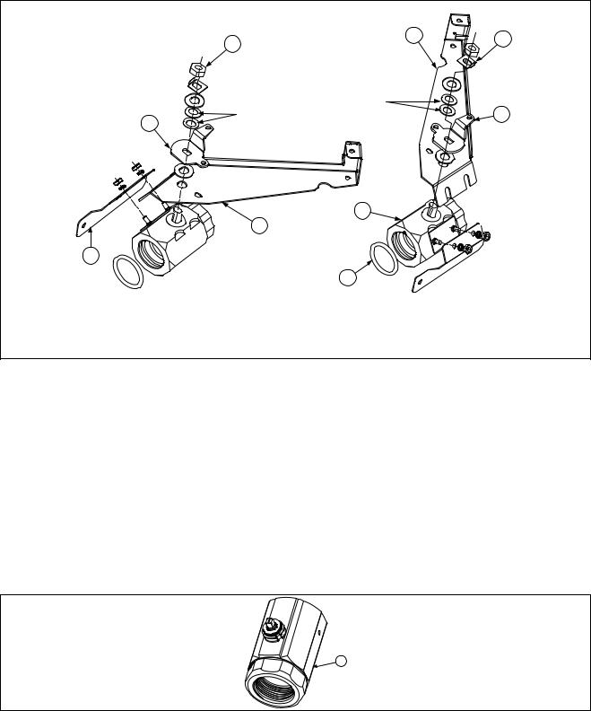
1.3.2Drain Valves and Associated Parts
1.3.2.1 Linear Actuator Drain Valves (12/2008-12/2011)
ITEM |
PART # |
COMPONENT |
1 |
8090540 |
Nut, ½-13 2-Way Hex Lock |
2 |
9002936 |
Retainer, Nut Drain Valve |
3 |
2325701 |
Handle, Drain Valve FV or DV Right |
4 |
2315701 |
Handle, Drain Valve DV Left |
5 |
8242048 |
Mount, Electric Drain Actuator Right |
6 |
8242047 |
Mount, Electric Drain Actuator Left |
7 |
2225962 |
Bracket, Drain to Valve LOV™ Electric |
8 |
8160544 |
O-Ring, Round Drain Seal |
9 |
8237231 |
Valve, 1¼-inch Drain LOV™ Electric Right (12/2008-12/2011) |
10 |
8237230 |
Valve, 1¼-inch Drain LOV™ Electric Left (12/2008-12/2011) |
1.3.2.2 Rotary Actuator Drain Valves (01/2012 – Present)
ITEM |
PART # |
COMPONENT |
1 |
8103755 |
Valve, 1¼-inch NPT Rotary Actuator (01/2012 – Present) |
1-4

1.4 Electronics and Wiring Components
1.4.1 Component Boxes
1-5

1.4.1 Component Boxes cont.
ITEM |
PART # |
COMPONENT |
11065592 Box Assembly, Component
22003300 Bracket, Component Box Strain Relief
38069495SP Terminal Block
√ |
4 |
8074346 |
Relay, 120V DPDT 20A (used in Canadian models only) |
√ |
5 |
8074482 |
Relay, Filter 2 Pole 30A DPDT 24VDC |
68070037 Terminal, ¼-inch Push-on
78070121 Bushing, Heyco Plastic AB-625-500
88070922 Holder, Buss Fuse HPS Screw Type
98072278 Fuse, 20 Amp
10 |
8102446 |
Plug, Button .50 Heyco Double “D” |
√ 11 |
8074036 |
Switch, Power |
|
8073575 |
Plug, Carling Switch Hole (used on some models without a switch) |
128071947 Plug, Button .875 Dome
138071321 Holder, AGC Panel Mount ¼” Fuse (Some models use item 10 here.)
148071597 Fuse, 3 AMP Slow-Blow
*8071174 Fuse, 3 AMP, 250V Slow-Blow
158102445 Plug, Button .625 Heyco Double “D”
161065750 Harness Assembly, RE FV Control
|
|
1065751 |
Harness Assembly, RE DV Control |
|
√ |
17 |
8070855 |
Transformer, 100-120V/12V 20VA |
|
√ |
18 |
8070800 |
Transformer, 100-120V/24V 50VA Filter (Used in FV component boxes) |
|
√ |
|
8074933 |
Transformer, 120/208/240/24V 75VA Filter (Used in DV component box) |
|
|
|
8074968 |
Transformer, 208-250V |
24V 75VA (Used in DV component box) |
|
|
8074967 |
Transformer, 100-120V |
75VA (Used in DV component box) |
√ |
19 |
8072181 |
Transformer, 100-120V |
/24V 62VA Filter |
√ |
20 |
8072191 |
Transformer, 208-240V/12V 30VA |
|
√ |
21 |
8070979 |
Transformer, 208-240V/12V 43VA |
|
√ |
22 |
8072180 |
Transformer, 208-240V/24V 50VA Filter |
|
238090349 Spacer, 4mm X 6mm Aluminum
24 Interface Board
√ |
|
8262260 |
Standard Full or Dual Vat Interface Board (includes sound harness) |
*8074403 Speaker, 4-Watt SMT
252204723 Guard, Finger w/ switch opening
268074678 Switch, Momentary Flush JIB Reset
272305038 Guard, RE Box Switch
288160217 Paper, Insulating Terminal Block
298100045 Bushing, .875 Diameter 11/16”
302006654 Brace, Component Box
√ 31 |
8074346 |
Relay, DPDT 20A 120V (used for control power reset in right hand boxes |
|
|
only in domestic and Canadian units) |
|
8074770 |
Relay, DPDT 20A 240V (resets control power; right hand boxes only in |
|
|
international units; one in each control box in some units.) |
32 |
8072659 |
Switch, Momentary (resets control power; located in box over JIB.) |
* |
8262249 |
RE Hood/Ansul Interlock Kit (includes terminal block, wires and connectors) |
* Not illustrated. |
|
|
√ Recommended parts. |
|
|
1-6
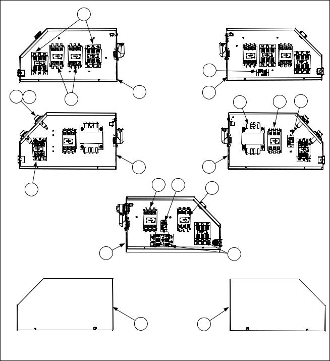
1.4.2Contactor Boxes
1.4.2.1 Left and Right Contactor Box Configurations
|
|
6 |
|
|
|
|
|
|
STANDARD |
|
|
|
|
|
|
MECHANICAL |
|
|
|
|
|
|
LEFT AND RIGHT |
|
|
|
|
|
|
CONFIGURATIONS |
7 |
|
|
|
8 |
9 |
1 |
|
2 |
|
|
5 |
|
10 |
5 |
7 |
||
|
|
120/440/480v |
|
|
|
|
|
|
LEFT AND RIGHT |
|
|
|
|
|
|
STANDARD AND |
|
|
|
|
|
|
MECHANICAL |
|
|
|
|
|
|
CONFIGURATIONS |
|
|
|
|
|
|
1 |
|
2 |
|
|
|
6 |
5 |
7 |
5 |
|
|
|
|
|
|
|
||
|
|
2 |
|
6 |
|
|
|
|
CANADIAN 14kW RIGHT |
|
|
||
|
|
CONFIGURATIONS |
|
|
||
|
|
3 |
|
4 |
|
|
|
|
LEFT HAND |
|
|
RIGHT HAND |
|
|
|
BOX COVER |
|
|
BOX COVER |
|
|
|
1-7 |
|
|
|
|
1.4.2.1 Left and Right Contactor Box Configurations cont.
NOTES: Left and right contactor box assemblies are mirror images of one another. With the exception of the box itself, all components of a left-hand assembly are the same as those in the corresponding right-hand assembly and vice versa except for the hood relay which occurs in the right or large box only. The configurations illustrated show all possible components, but a particular configuration may not have all the components shown.
ITEM |
PART # |
COMPONENT |
|
|
1 |
8241896SP |
Box Assembly, Left Contactor |
|
2 |
1068660 |
Box Assembly, Right Contactor |
|
3 |
2210482 |
Cover, Left Hand Contactor Box |
|
4 |
2220482 |
Cover, Right Hand Contactor Box |
|
9 |
8070070 |
Terminal, Ground Lug |
√ |
5 |
8072284 |
Contactor, 24V 50 Amp Mechanical (Heat) |
√ |
6 |
8101202 |
Contactor, 24V 40 Amp Mechanical (Latch) |
|
7 |
8071683 |
Relay, Hood 12VDC |
|
8 |
8070922 |
Holder, Bus Fuse |
|
9 |
8072278 |
Fuse, 20 Amp |
|
10 |
8070064 |
Transformer, 480V/120V 150VA |
|
* |
2210610 |
Bracket, Left Hand Contactor Box Mounting |
|
* |
2220610 |
Bracket, Right Hand Contactor Box Mounting |
|
* |
8074316 |
McDonald’s Cordset, 120V 5-Wire |
|
* |
8074317 |
McDonald’s Cordset, Europe 3-Wire Single Phase |
|
* |
8070012 |
Relay, Tilt Switch 18 Amp 1/3 HP 24 V Coil |
*Not illustrated.
√Recommended parts.
1-8
 Loading...