


Universal Frequency
Counter
PM6669
Operators Manual

CONTENTS |
Page: 1 |
CONTENTS
SAFETY ........................................................................... |
2 |
Introduction ................................................................... |
2 |
PRODUCT PRESENTATION ......................................... |
3 |
General ......................................................................... |
3 |
Rear View...................................................................... |
3 |
Front View ..................................................................... |
4 |
INSTALLATION ............................................................... |
5 |
Unpacking ..................................................................... |
5 |
Voltage-Range Selection .............................................. |
5 |
Grounding ..................................................................... |
5 |
Connecting External Reference.................................... |
6 |
Installing Options .......................................................... |
6 |
Calibrating the MTCXO................................................. |
6 |
OPERATING INSTRUCTIONS........................................ |
8 |
Using the Frequency Counter....................................... |
8 |
Battery Unit ................................................................ |
20 |
Error Codes................................................................. |
20 |
GPIB-INTERFACE OPERATION .................................. |
21 |
Introduction ................................................................. |
21 |
What Can I Do Using the Bus?................................... |
21 |
Connecting the Controller ........................................... |
22 |
Giving the Counter an Address................................... |
22 |
Checking the Communication..................................... |
22 |
Two Ways of Programming......................................... |
23 |
Syntax ......................................................................... |
23 |
Selecting Output Separator......................................... |
24 |
How to Select Function ............................................... |
24 |
Selecting Measuring-Time........................................... |
24 |
Selecting Triggering..................................................... |
25 |
Totalize Start/Stop ....................................................... |
25 |
Free-Run/Triggered ..................................................... |
25 |
Service Request .......................................................... |
26 |
Status Byte .................................................................. |
26 |
Output Mode................................................................ |
27 |
Bus Learn .................................................................... |
30 |
Programming Data Out ............................................... |
30 |
What Happens When I Switch to Local?..................... |
30 |
Summary of Bus Commands ...................................... |
31 |
Programming Examples.............................................. |
32 |
SPECIFICATIONS ......................................................... |
35 |
Measuring Functions................................................... |
35 |
Definitions.................................................................... |
36 |
Input specifications...................................................... |
36 |
General Information..................................................... |
37 |
Auxiliary Functions ...................................................... |
38 |
Optional Accessories................................................... |
38 |
Ordering Information .................................................. |
40 |
APPENDIX 1 .................................................................. |
41 |
Checking the Sensitivity of Counters .......................... |
41 |
INDEX ............................................................................ |
43 |
4822 872 20021
5/12-April-1995
PM 6669 - OPERATORS MANUAL
Page: 2 |
SAFETY |
SAFETY
Introduction
Read this page carefully before you install and use the PM 6669 Frequency Counter.
This Frequency Counter has been designed and tested in accordance with IEC publication 1010-1, and CSA 22.2 No.231, and has been supplied in a safe condition. The user of this instrument must have the required knowledge of PM 6669. This knowledge can be gained by thoroughly studying this manual.
Safety Precautions
Use generally-accepted safety procedures, in addition to the safety precautions stated in this manual, to ensure personal safety and safe operation of the Frequency Counter.
Caution & Warning Statements
You will find specific warning and caution statements, where necessary throughout the manual. Do not carry out repairs or adjustments to the Frequency Counter without reading the Service Manual, which contains the relevant warnings for such activities.
CAUTION: Indicates where incorrect operating procedures can cause damage to, or destruction of, equipment or other property.
WARNING: Indicates a potential danger that requires correct procedures or practices in order to prevent personal injury.
Symbols
Indicates where the protective ground lead is connected inside the instrument. Never unscrew or loosen this screw.
If in doubt about safety
Whenever you suspect that it is unsafe to use the instrument, you must make it inoperative, clearly mark it to prevent its further operation, and inform the Fluke service Centre.
E.g.The instrument is likely to be unsafe if it is visibly damaged.
PM 6669 - OPERATORS MANUAL
PRODUCT PRESENTATION |
Page: 3 |
PRODUCT PRESENTATION
General
The PM 6669 is a compact, high resolution, reciprocal Frequency Counter which performs many functions. A number of options are available i.e. HF-input, GPIB-interface, high stability oscillator, and rechargeable battery for field use.
A rack-mount kit and a carrying case are also available as accessories.
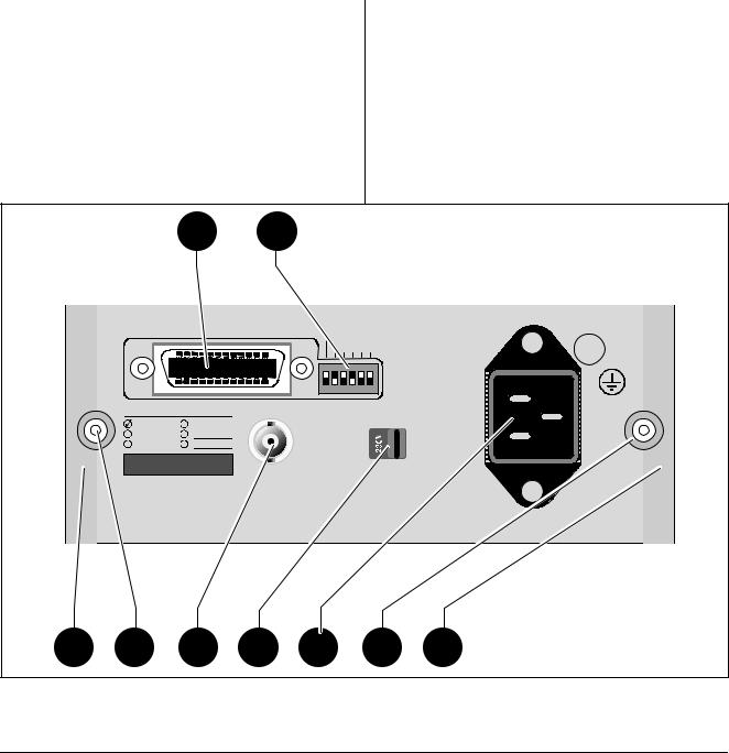
Rear View
A)Rear feet.
B)Screws for removing the cover.
C)External-reference-input, BNC connector.
D)Voltage-range selector.
E)Power-inlet socket.
F)GPIB interface-connector (optional).
G)GPIB address-selector ( option).
|
|
|
F |
G |
|
|
|
|
|
|
|
|
IEEE 488 INTERFACE |
|
|
|
|
SUPPORTED |
|
|
|
|
TALK ONLY |
|
|
|
FUNCTIONS: |
||
|
|
|
|
|
|
|
|
||
|
|
|
|
|
ADDRESS |
SH1,AH1 |
|||
|
|
|
|
|
16 8 |
4 |
2 |
1 |
T5,L4 |
|
|
|
|
|
|
|
|
|
SR1,RL1 |
|
|
|
|
|
|
|
|
|
DC1,DT1 |
|
|
|
|
|
|
|
|
ON |
E2 |
|
|
|
|
|
|
|
|
OFF |
|
|
|
INCLUDED OPTIONS |
EXT REF INPUT |
|
|
VOLTAGE |
|
||
|
|
PM 9604 |
PM 9608B |
|
|
|
|
SELECTOR |
|
|
|
|
|
|
|
|
|
||
|
|
PM 9605 |
|
|
|
|
|
|
|
|
|
PM 9607 |
|
|
|
|
|
|
|
|
|
|
|
10MHz 0.5-15Vrms |
|
|
|
|
|
|
|
|
|
|
|
|
|
|
THERMAL FUSE IN |
|
|
|
|
|
|
|
|
|
MAINS TRANSFORMER |
|
A |
B |
C |
D |
E |
|
|
B |
A |
Figure 1 |
Rear View. |
|
|
|
|
|
|
|
|
PM 6669 - OPERATORS MANUAL
Page: 4 |
PRODUCT PRESENTATION |
|
|
|
H |
|
|
J |
K |
|
|
|
|
|
|
L |
M |
||
|
|
|
PM 6669 |
UNIVERSAL FREQUENCY COUNTER |
|
|
|
|
|
160MHz/1.3GHz |
|||||||
|
|
MEASURING TIME |
|
|
DISPL |
TRIGGER LEVEL A |
|
INPUT A |
|
INPUT B |
|||||||
|
|
SINGLE |
0.2s |
1s |
|
10s |
HOLD |
AUTO |
|
|
|
|
|
|
|||
|
|
|
|
|
|
|
|
|
|
|
|
|
|
FILTER<50kHz |
|
OPTION |
|
|
|
|
|
|
|
|
|
|
|
|
|
|
|
SENSITIVITY |
|
|
|
|
|
FREQ |
FREQ |
FREQ |
|
FREQ |
RPM |
PER |
TOT |
WIDTH |
EXT |
|
|
|
|
||
|
|
A |
B |
A/Ao |
|
A-Ao |
A |
A |
A |
|
A |
|
REF |
MIN |
10mVrms |
|
|
|
|
|
|
|
|
|
|
|
|
|
|
|
|
|
|
||
|
|
|
|
|
|
|
|
|
|
|
|
|
|
|
200mVrms |
|
|
|
|
ON |
RESET |
MEAS |
FUNCTION |
DISPL |
|
BLANK |
TRIGGER |
|
A |
|
|
||||
|
|
|
10Hz-160MHz |
|
70MHz - 1.3GHz |
||||||||||||
|
|
STANDBY |
LOCAL |
|
TIME |
|
HOLD |
|
DIGITS |
LEVEL A |
|
||||||
|
|
|
|
|
|
|
|
|
|
|
|
|
|
1MΩ |
|
50 Ω |
|
|
|
|
TOTALIZE A |
|
|
|
STORE |
|
|
|
|
|
30pF |
|
|
|
|
|
|
|
|
|
|
|
|
|
|
|
|
|
|
|
|||
|
|
|
START/STOP |
|
|
|
Ao |
|
|
|
|
|
|
MAX 350Vp |
|
MAX 12Vrms |
|
|
|
|
|
|
|
|
|
|
|
|
|
|
|
|
|
||
|
N |
O |
P |
|
|
R |
S |
|
T |
|
U |
|
|
V |
|||
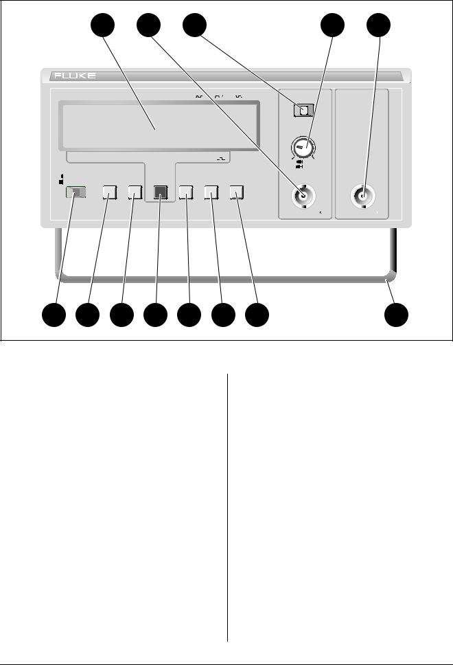
Figure 2 |
Front View. |
|
|
|
|
|
|
|
|
|
|
|
|
|
|
|
|
Front View
H)Large LCD-display.
J)Input-A BNC-connector.
K)Sensitivity control with dual-range push-in/pull-out switch.
L)50 kHz filter switch (Input-A).
M)Input-B BNC-connector (optional).
N)Power switch.
O)Reset button, doubles as Local button if the Frequency Counter is equipped with an GPIB interface. Starts and stops counting if the TOT A function is selected.
P)Measuring-time selector-button. *
R)Function-selector button. *
S)Display-hold button. Freezes the display. The button is also used for storing A0.
T)Blank digits button. Blanks out one digit for each depression of the button, from the right to the left of the display. (No rounding off).
U)Trigger level setting button.
V)Tilting support.
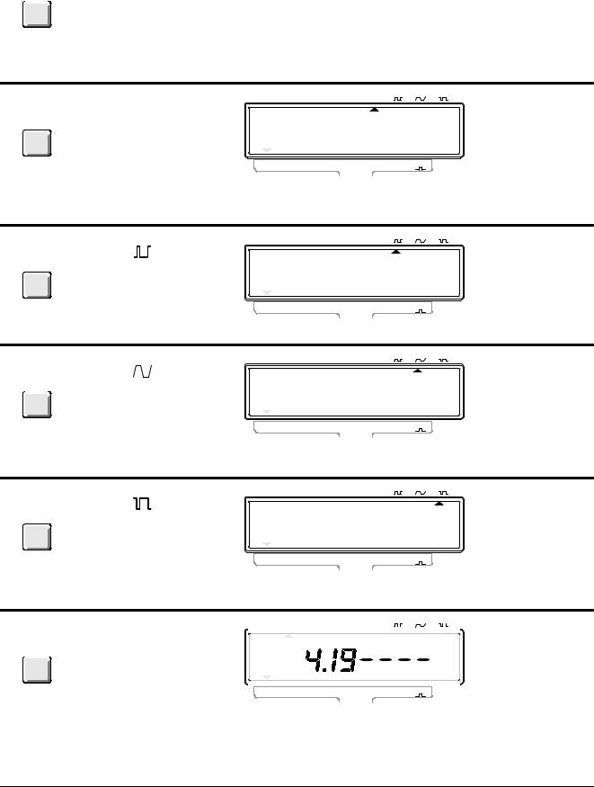
*The selected function is indicated on the display. A short press on the button moves the cursor one step to the right. A long press makes the cursor scroll.
PM 6669 - OPERATORS MANUAL
INSTALLATION |
Page: 5 |
INSTALLATION
Unpacking
If the Frequency Counter is cold, leave it in the cardboard box until it has reached normal room temperature.
–Lift the Frequency Counter out of the box.
–Remove the polystyrene supports.
–Unpack the Frequency Counter from the plastic bag.
–Reverse the procedure to pack.
Check List
Has the Frequency Counter been damaged in transport? If it has, file a claim with the carrier immediately, and notify the Fluke sales & service organization to make repair or replacement of the instrument easier.
–Check that the package contains the following items in addition to the Frequency Counter:
–This Operators’ Manual
–A power cable with protective earth conductor
–A Battery unit if ordered *)
–An MTCXO oscillator if ordered *)
–A GPIB interface if ordered *)
–An HF-input if ordered *)
*) Labels on the rear panel indicate which options are fitted in your Frequency Counter.
INCLUDED OPTIONS
PM 9604  PM 9608B
PM 9605
PM 9607
Figure 3 Options Label on Rear Panel.
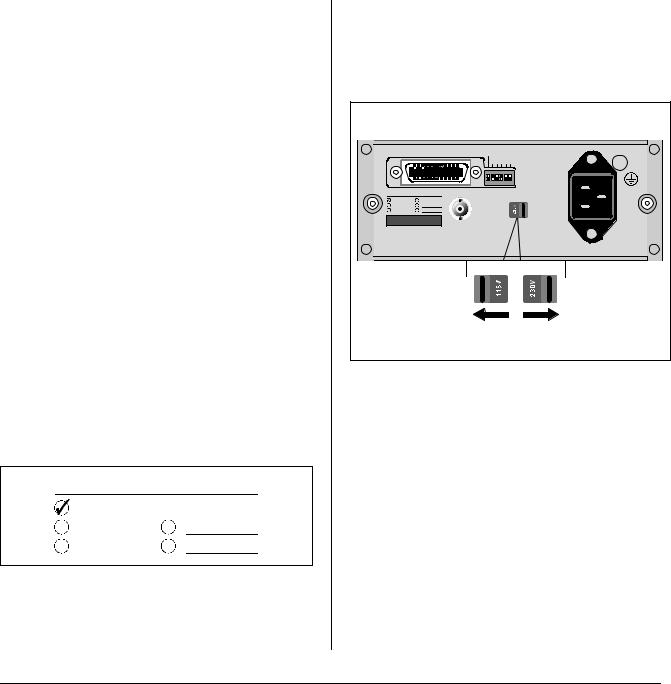
Voltage-Range Selection
Set the Frequency Counter to the local line voltage before connecting it. As delivered the Frequency Counter may be set to either 115 V or 230 V. The setting is indicated on the voltage range selector on the rear panel.
|
IEEE 488 INTERFACE |
|
|
|
|
SUPPORTED |
|
|
TALK ONLY |
|
|
|
FUNCTIONS: |
||
|
|
|
ADDRESS |
SH1,AH1 |
|||
|
|
|
16 8 |
4 |
2 |
1 |
T5,L4 |
|
|
|
|
|
|
|
SR1,RL1 |
|
|
|
|
|
|
ON |
DC1,DT1 |
|
|
|
|
|
|
E2 |
|
|
|
|
|
|
|
OFF |
|
INCLUDED OPTIONS |
EXT REF INPUT |
|
|
VOLTAGE |
|
||
PM 9604 |
PM 9608B |
|
|
|
|
SELECTOR |
|
|
|
|
|
|
|
||
PM 9605 |
|
|
|
|
|
|
|
PM 9607 |
|
|
|
|
|
|
|
|
|
10MHz 0.5-15Vrms |
|
|
|
|
|
|
|
|
|
|
|
|
THERMAL FUSE IN |
|
|
|
|
|
|
|
MAINS TRANSFORMER |
Figure 4 Location of Voltage Range Selector.
If the voltage range setting is incorrect, set the selector in accordance with the local voltage before connecting the power cable to the line.
Grounding
The Frequency Counter is connected to ground via a sealed three-core power cable, which must be plugged into a socket outlet with a protective ground terminal. No other grounding is permitted for this Frequency Counter. Extension cables must always have a protective ground conductor.
PM 6669 - OPERATORS MANUAL
Page: 6 |
INSTALLATION |
WARNING: Never interrupt the protective grounding intentionally. Any interruption of the protective ground connection inside or outside the instrument, or disconnection of the protective ground terminal is likely to make the instrument dangerous.
Connecting External
Reference
If you wish to use an external 10 MHz reference frequency source, connect it via a BNC-cable to the EXT REF INPUT on the rear panel of the Frequency Counter.
When the Frequency Counter starts measuring, it automatically detects the external reference and begins to use it. The EXT REF indicator on the display is switched on.
Installing Options
Introduction
The options ordered at the same time as the Frequency Counter are normally factory-installed. Other options can be fitted when needed.
The options fit inside the Frequency Counter, but not all at the same time: The HF-input, the high stability-oscillator and either of the GPIB-interface or the Battery-unit can be installed in one and the same Frequency Counter.
Calibrating the MTCXO
The MTCXO Time-base can easily be recalibrated to any 10 MHz reference. To maintain the accuracy of the MTCXO, use a reference with an accuracy of 3*10-8.
The PM 9691 oven-enclosed oscillator used in Fluke counters version /.5. meet this requirement, if calibrated.
Preparations
If you remove the cover when counter has been switched on, the temperature of the MTCXO will rapidly drop about 10°C. Since the MTCXO must have a stable temperature when calibrated you must wait an hour between removing the cover and calibrating.
If the counter has been switched off more than three hours, you can calibreate it directly.
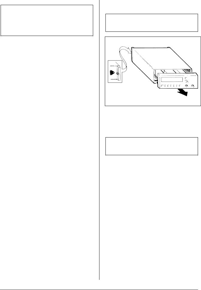
Removing the Cover
WARNING: When you remove the cover you will expose live parts and accessible terminals which can be dangerous to life.
Loosen the two screws
using a Pozidrive No. 1 screwdriver
Figure 5 Loosen These Screws to Remove Cover.
– Make sure that the power cable is disconnected.
WARNING: Although the power switch is in the off position, the line voltage is present on the printed circuit board.
–Loosen the two screws in the rear feet.
–Grip around the front panel and pull the Frequency Counter out of the cover.
Calibration Procedure
–Remove the cover from the counter.
–Allow the MTCXO to adapt the new ambient temperature. (See ’Preparations’.)
–Connect the 10 MHz reference to Input-A.
–Switch ON the counter.
–Adjust the sensitivity control so that the counter counts properly.
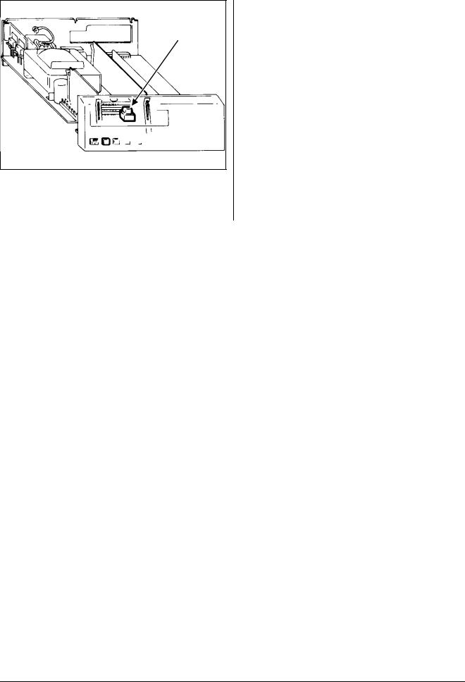
–Hold down the CALIB-button, on the main printed-circuit board in the counter, and press the Reset-button.
PM 6669 - OPERATORS MANUAL
INSTALLATION |
Page: 7 |
CALIB-button
Figure 6 Location of the CALIB-Button.
–Wait about 20 seconds, until the display shows 10.0000000 MHz. Now the oscillator is calibrated.
–Switch OFF the counter and disconnect the 10 MHz reference.
Fit the cover.
PM 6669 - OPERATORS MANUAL
Page: 8 |
OPERATING INSTRUCTIONS |
OPERATING INSTRUCTIONS
Using the Frequency Counter
CONTROL OPERATING THE |
DISPLAY |
GPIB-CODE |
CONTROL |
|
|
|
|
|
 ON
ON  STAND-BY
POWER, a two-position mechanical push-button. Pressed = ON, Released = OFF
|
MEASURING TIME |
DISPL |
TRIGGER LEVEL A |
|
|||
|
SINGLE 0.2s |
1s |
10s HOLD |
AUTO |
|
|
|
|
|
|
|
|
|
|
|
|
|
|
|
|
|
|
|
No control possible but D gives the same settings as after power-ON.
|
FREQ |
FREQ |
FREQ |
FREQ |
RPM |
PER |
TOT |
WIDTH |
EXT |
|
||||
|
A |
B |
A/A0 |
A-A0 |
A |
A |
A |
A |
REF |
|
||||
|
|
|
|
|
FUNCTION |
|
|
|
|
|
|
|
|
|
|
MEASURING TIME |
|
DISPL |
AUTO |
TRIGGER LEVEL A |
|
||||||||
|
SINGLE |
0.2s |
1s |
10s |
HOLD |
|
|
|
|
|
|
|
|
|
|
|
|
|
|
|
|
|
|
||||||
|
|
|
|
|
|
|
|
|
|
|
|
|
|
|
|
|
|
|
|
|
|
|
|
|
|
|
|
|
|
MkHz 0.ums
GATE
FREQ |
FREQ |
FREQ |
FREQ |
RPM |
PER |
TOT |
WIDTH |
EXT |
A |
B |
A/A0 |
A-A0 |
A |
A |
A |
A |
REF |
|
|
|
|
FUNCTION |
|
|
|
|
|
|
|
|
|
|
|
|
|
|
A short depression of |
One code for |
FUNCTION |
the FUNCTION key |
each function, |
|
moves the cursor in the |
- see below: |
|
lower edge of the |
|
|
display one step to the |
|
|
right. If the key is held |
|
|
depressed, the cursor |
|
|
will scroll to the right |
|
|
until released. When the |
|
|
cursor reaches the |
|
|
rightmost position it |
|
|
jumps back to the |
|
|
leftmost position and |
|
|
continues from there. |
|
|
|
|
|
Move function cursor to |
FUNCTION |
FREQ A |
MEASURING TIME |
|
DISPL |
AUTO |
TRIGGER LEVEL A |
|
FREQ A |
||||||||
SINGLE |
0.2s |
1s |
10s |
HOLD |
|
|
|
|
|
|
|
|
||
|
|
|
|
|
|
|
|
|
|
|
|
|
|
|
|
|
|
|
|
|
|
|
|
|
|
|
|
|
|
|
|
|
|
|
|
|
|
|
0.kHz |
|
|
|||
|
|
|
|
|
|
|
|
|
|
|
|
|
|
|
|
|
|
|
|
|
|
|
|
|
|
|
|
|
|
FREQ |
FREQ |
FREQ |
FREQ |
RPM |
PER |
TOT |
WIDTH |
EXT |
|
|
||||
A |
B |
A/A0 |
A-A0 |
A |
A |
A |
A |
REF |
|
|
||||
FUNCTION
PM 6669 - OPERATORS MANUAL

OPERATING INSTRUCTIONS |
Page: 9 |
FUNCTION AND RANGE |
HINTS AND COMMENTS |
Switches the power ON and OFF. When switched on, the built in microprocessor switches on all segments of the display then it runs a power-up test, checking the measuring-logic of the Frequency Counter before the counter starts working. This test takes about 2 seconds.
If an error is found, an error code will be displayed. Try switching the Frequency Counter off and on again. If error code 01 - 03 persists, call Fluke service. Look on the last page in this manual for Phone No. and address.
WARNING:The power switch operates on the secondary side of the transformer. The power cable must be disconnected from the line outlet socket if it is necessary to completely isolate the Frequency Counter from the line.
Error 01 = RAM memory error Error 02 = Measuring logic error Error 03 = Internal bus error
Error OF = Overflow in the counting registers
Selects one of the nine measuring functions available.
The cursor does not stop at FREQ C if no Input-C HFinput is installed.
Reciprocal frequency measurement of the signal at In- put-A.
Range:
0.1 Hz to 16 MHz (SINGLE measuring-time)
1 Hz to 160 MHz (0.2, 1, and 10 s measuring-time)
If the signal is sine shaped and the input AC coupled, the minimum input frequency is 20 Hz (at specified sensitivity).
PM 6669 - OPERATORS MANUAL
Page: 10 |
OPERATING INSTRUCTIONS |
CONTROL |
OPERATING THE |
DISPLAY |
|
|
|
|
|
|
|
|
GPIB-CODE |
|
CONTROL |
|
|
|
|
|
|
|
|
|
|
|
Move function cursor to |
MEASURING TIME |
|
DISPL |
AUTO |
TRIGGER LEVEL A |
FREQ B |
||||
|
SINGLE |
0.2s |
1s |
10s |
HOLD |
|
|
|
|||
FUNCTION |
FREQ B |
|
|
|
|
|
|
|
|
|
|
|
|
|
|
|
|
|
|
|
0.kHz |
|
|
|
|
FREQ |
FREQ |
FREQ |
FREQ |
RPM |
PER |
TOT |
WIDTH |
EXT |
|
|
|
A |
B |
A/A0 |
A-A0 |
A |
A |
A |
A |
REF |
|
|
|
|
|
|
|
FUNCTION |
|
|
|
|
|
|
Move function cursor to |
MEASURING TIME |
|
DISPL |
AUTO |
TRIGGER LEVEL A |
Not bus |
||||
|
SINGLE |
0.2s |
1s |
10s |
HOLD |
|
|
|
|||
FUNCTION |
FREQ A/A0 |
|
|
|
|
|
|
|
|
|
selectable |
|
|
|
|
|
|
|
|
|
0. |
|
|
|
|
FREQ |
FREQ |
FREQ |
FREQ |
RPM |
PER |
TOT |
WIDTH |
EXT |
|
|
|
A |
B |
A/A0 |
A-A0 |
A |
A |
A |
A |
REF |
|
FUNCTION
|
Move function cursor to |
MEASURING TIME |
|
DISPL |
AUTO |
TRIGGER LEVEL A |
Not bus |
||||
|
SINGLE |
0.2s |
1s |
10s |
HOLD |
|
|
|
|||
FUNCTION |
FREQ A-A0 |
|
|
|
|
|
|
|
|
|
selectable |
|
|
|
|
|
|
|
|
|
0. |
|
|
|
|
FREQ |
FREQ |
FREQ |
FREQ |
RPM |
PER |
TOT |
WIDTH |
EXT |
|
|
|
A |
B |
A/A0 |
A-A0 |
A |
A |
A |
A |
REF |
|
|
|
|
|
|
|
FUNCTION |
|
|
|
|
|
|
Move function cursor to |
MEASURING TIME |
|
DISPL |
AUTO |
TRIGGER LEVEL A |
RPM A |
||||
|
SINGLE |
0.2s |
1s |
10s |
HOLD |
|
|
|
|||
FUNCTION |
RPM A |
|
|
|
|
|
|
|
|
|
|
|
|
|
|
|
|
|
|
|
0. |
|
|
|
|
FREQ |
FREQ |
FREQ |
FREQ |
RPM |
PER |
TOT |
WIDTH |
EXT |
|
|
|
A |
B |
A/A0 |
A-A0 |
A |
A |
A |
A |
REF |
|
|
|
|
|
|
|
FUNCTION |
|
|
|
|
|
|
Move function cursor to |
MEASURING TIME |
|
DISPL |
AUTO |
TRIGGER LEVEL A |
PER A |
||||
|
SINGLE |
0.2s |
1s |
10s |
HOLD |
|
|
|
|||
FUNCTION |
PER A |
|
|
|
|
|
|
|
|
|
|
|
|
|
|
|
|
|
|
|
0.ms |
|
|
|
|
FREQ |
FREQ |
FREQ |
FREQ |
RPM |
PER |
TOT |
WIDTH |
EXT |
|
|
|
A |
B |
A/A0 |
A-A0 |
A |
A |
A |
A |
REF |
|
|
|
|
|
|
|
FUNCTION |
|
|
|
|
|
|
Move function cursor to |
MEASURING TIME |
|
DISPL |
AUTO |
TRIGGER LEVEL A |
TOTM A |
||||
|
SINGLE |
0.2s |
1s |
10s |
HOLD |
|
|
|
|||
FUNCTION |
TOT A |
|
|
|
|
|
|
|
|
|
|
|
|
|
|
|
|
|
|
|
0. |
|
|
|
|
FREQ |
FREQ |
FREQ |
FREQ |
RPM |
PER |
TOT |
WIDTH |
EXT |
|
|
|
A |
B |
A/A0 |
A-A0 |
A |
A |
A |
A |
REF |
|
FUNCTION
PM 6669 - OPERATORS MANUAL

OPERATING INSTRUCTIONS |
Page: 11 |
FUNCTION AND RANGE |
HINTS AND COMMENTS |
Reciprocal frequency measurement of the signal at In- put-B.
Range:
70 to 1300 MHz (PM 9608B)
The cursor does not stop at FREQ B if no Input-B HFinput is installed.
The counter divides the frequency on Input-A by a constant, A0, that is stored in the counter in the following way:
1)Connect a signal with the frequency to be stored as A0 to Input-A.
2)Select FREQ A.
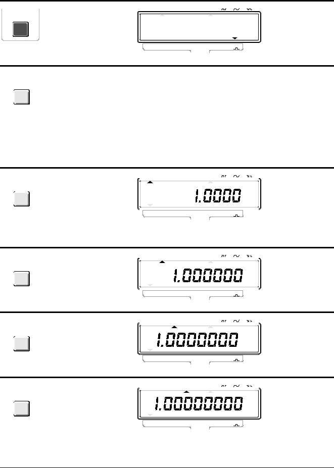
3)Depress the DISPL HOLD key and hold it depressed until the DISPL HOLD indicator is switched off again. Now A0 is stored.
4)Select FREQ A/A0.
5)Connect the frequency to be measured to Input-A.
If you select this function without storing A0, Frequency A will be displayed.
This function is convenient when an oscillator is to be tuned to the frequency of a reference oscillator. It is much easier to adjust until the display shows 1.0000000 than 7.1223678.
The counter substracts a constant, A0, from the fre- |
If you select this function without storing A0, |
|
quency at Input-A. You can read about how to store |
Frequency A will be displayed. |
|
A0 in the description for FREQ A/A0. |
|
|
|
|
This function can e.g. be used in a radio to display |
|
|
the received frequency; Set the intermediate |
|
|
frequency as the constant A0. Select FREQ A-A0 and |
|
|
measure the frequency of the local oscillator, and the |
|
|
display will show the received frequency. |
|
|
|
The frequency on Input-A is multiplied by 60 and dis- |
|
|
played as Revolutions Per Minute. |
|
|
Range: |
6 RPM to 720 000 000 RPM. |
|
When you select SINGLE, the Frequency Counter measures one period, the range is: 100 ns to 200 000 000 s (about 6 years and four months!).
When you select 0.2, 1, and 10 s Measuring-time, the Frequency Counter divides the input frequency by 10 and measures the average period for the No. of cycles in that time.
Range:
8 ns to 1 s.
Use SINGLE when the input frequency is low. This shortens the measuring time considerably since one cycle is measured instead of 10.
The Frequency Counter counts the total number of pulses fed to Input-A. You start and stop the totalizing with the TOTALIZE START/STOP key (RESET/LOCAL). If you keep this key depressed for more than one second, the total sum will be reset.
Range:
0 to 1*1015 pulses
k on the display indicates kilo-pulses (1000) and M indicates Mega-pulses(1 000 000).
The Measuring-time indicator is switched off in TOT A MAN.
PM 6669 - OPERATORS MANUAL
Page: 12 |
OPERATING INSTRUCTIONS |
CONTROL |
OPERATING THE |
DISPLAY |
|
|
|
|
|
|
|
|
GPIB-CODE |
|
CONTROL |
|
|
|
|
|
|
|
|
|
|
|
Move function cursor to |
MEASURING TIME |
|
DISPL |
AUTO |
TRIGGER LEVEL A |
WIDTH A or |
||||
|
SINGLE |
0.2s |
1s |
10s |
HOLD |
|
|
|
|||
FUNCTION |
WIDTH A |
|
|
|
|
|
|
|
|
|
PWIDTH A |
|
|
|
|
|
|
|
|
|
0.ms |
|
|
|
|
FREQ |
FREQ |
FREQ |
FREQ |
RPM |
PER |
TOT |
WIDTH |
EXT |
|
|
|
A |
B |
A/A0 |
A-A0 |
A |
A |
A |
A |
REF |
|
FUNCTION
MEAS TIME
MEAS TIME is operated |
MTIME <num> |
in the same way as the |
where <num> |
func-tions control, see |
is the time in |
page 8. |
seconds. |
|
Range: |
|
10 ms to 10 s. |
|
0 = Single |
Move the measuring-
MEAS time cursor to SINGLE
TIME
MEASURING TIME |
|
DISPL |
AUTO |
TRIGGER LEVEL A |
||||||||
SINGLE |
0.2s |
1s |
10s |
HOLD |
|
|
|
|
|
|
|
|
|
|
|
|
|
|
|
||||||
|
|
|
|
|
|
|
|
|
|
|
|
|
|
|
|
|
|
|
|
|
|
|
|
|
|
|
|
|
|
|
|
|
|
|
|
kHz |
||
|
|
|
|
|
|
|
|
|
|
|
|
|
|
|
|
|
|
|
|
|
|
|
|
|
|
|
|
|
|
|
|
|
|
|
|
|
|
|
FREQ |
FREQ |
FREQ |
FREQ |
RPM |
PER |
TOT |
WIDTH |
EXT |
||||
A |
B |
A/A0 |
A-A0 |
A |
A |
A |
A |
REF |
||||
FUNCTION
MTIME 0
Move the measuring-
MEAS time cursor to 0.2 s
TIME
MEASURING TIME |
|
DISPL |
AUTO |
TRIGGER LEVEL A |
||||||||
SINGLE |
0.2s |
1s |
10s |
HOLD |
|
|
|
|
|
|
|
|
|
|
|
|
|
|
|
||||||
|
|
|
|
|
|
|
|
|
|
|
|
|
|
|
|
|
|
|
|
|
|
|
|
|
|
|
|
|
|
|
|
|
|
|
|
kHz |
||
|
|
|
|
|
|
|
|
|
|
|
|
|
|
|
|
|
|
|
|
|
|
|
|
|
|
|
|
|
|
|
|
|
|
|
|
|
|
|
FREQ |
FREQ |
FREQ |
FREQ |
RPM |
PER |
TOT |
WIDTH |
EXT |
||||
A |
B |
A/A0 |
A-A0 |
A |
A |
A |
A |
REF |
||||
FUNCTION
MTIME 0.2
Move the measuring-
MEAS time cursor to 1 s
TIME
|
MEASURING TIME |
DISPL |
TRIGGER LEVEL A |
|
|||||
|
SINGLE 0.2s |
1s |
10s HOLD |
AUTO |
|
|
|
|
|
|
|
|
|
|
|
|
|
|
|
|
|
|
|
|
|
|
|
|
|
kHz
MTIME 1
FREQ |
FREQ |
FREQ |
FREQ |
RPM |
PER |
TOT |
WIDTH |
EXT |
A |
B |
A/A0 |
A-A0 |
A |
A |
A |
A |
REF |
|
|
|
|
FUNCTION |
|
|
|
|
Move the measuring -
MEAS time cursor to 10 s
TIME
|
MEASURING TIME |
DISPL |
TRIGGER LEVEL A |
|
|||||
|
SINGLE 0.2s |
1s |
10s HOLD |
AUTO |
|
|
|
|
|
|
|
|
|
|
|
||||
|
|
|
|
|
|
|
|
|
|
|
|
|
|
|
|
|
|
|
|
kHz
MTIME 10
FREQ |
FREQ |
FREQ |
FREQ |
RPM |
PER |
TOT |
WIDTH |
EXT |
A |
B |
A/A0 |
A-A0 |
A |
A |
A |
A |
REF |
|
|
|
|
FUNCTION |
|
|
|
|
PM 6669 - OPERATORS MANUAL

OPERATING INSTRUCTIONS |
Page: 13 |
FUNCTION AND RANGE |
HINTS AND COMMENTS |
The counter measures the positive pulse width of the signal on Input-A.
Range:
100 ns to 200 000 000 s.
If you are interested in the negative pulse width instead; first measure the period and make a note of the result, then measure the pulse width and substract it from the period reading.
The set Measuring-time controls the time during |
If you wish to do one measurement instead of |
which the main gate is opened, allowing pulses to en- |
repetitive measurements, see DISPL HOLD. |
ter the counting logic. A longer Measuring-time gives |
|
higher resolution readouts with more digits displayed. |
|
The time the gate is open is not exactly the preset |
|
Measuring-time, because the Frequency Counter syn- |
|
chronizes the measurement with the input signal in or- |
|
der to measure complete periods. If the period of the |
|
input signal is longer than the set Measuring-time, the |
|
main gate does not close again until the period is |
|
completed. |
|
|
|
For PER A and WIDTH exactly one period or one |
The input frequency is limited to 16 MHz for FREQ A, |
time interval is measured. The minimum result possi- |
PER A, and RPM A. |
ble is 100 ns. |
|
|
If external reference is used, the EXT REF indicator |
The display time will be 100 ms. |
will not be switched-on until after the first |
|
measurement. |
When set to SINGLE, FREQ A and, RPM A, the |
|
Measuring-time is one cycle of the input signal or |
|
3 ms, whichever is longest. When set to SINGLE and |
|
FREQ B, the Measuring-time is 3 ms. |
|
|
|
A Frequency-A measurement will result in 6-7 digits |
|
on the display. |
|
A Frequency-A measurement will result in 7-8 digits on the display.
A Frequency-A measurement will result in 8-9 digits on the display.
PM 6669 - OPERATORS MANUAL
Page: 14 |
OPERATING INSTRUCTIONS |
CONTROL OPERATING THE |
DISPLAY |
GPIB-CODE |
CONTROL |
|
|
|
|
|
TRIGGER LEVEL A
The TRIGGER |
One code for |
LEVEL A control is |
each trigger |
operated in the same |
level offset. |
way as the functions |
See below. |
control, see page 8. |
|
|
Move Trigger Level A |
MEASURING TIME |
|
DISPL |
AUTO |
TRIGGER LEVEL A |
TLO AUT |
||||
|
SINGLE |
0.2s |
1s |
10s |
HOLD |
|
|
|
|||
TRIGGER |
cursor to AUTO. |
|
|
|
|
|
|
|
|
|
|
LEVEL A |
|
|
|
|
|
|
|
|
|
kHz |
|
|
|
|
|
|
|
|
|
|
0. |
|
|
|
|
FREQ |
FREQ |
FREQ |
FREQ |
RPM |
PER |
TOT |
WIDTH |
EXT |
|
|
|
A |
B |
A/A0 |
A-A0 |
A |
A |
A |
A |
REF |
|
FUNCTION
|
Move Trigger Level A |
MEASURING TIME |
|
DISPL |
AUTO |
TRIGGER LEVEL A |
TLO POS |
||||
|
SINGLE |
0.2s |
1s |
10s |
HOLD |
|
|
|
|||
TRIGGER |
cursor to |
|
|
|
|
|
|
|
|
|
|
LEVEL A |
|
|
|
|
|
|
|
|
|
kHz |
|
|
|
|
|
|
|
|
|
|
0. |
|
|
|
|
FREQ |
FREQ |
FREQ |
FREQ |
RPM |
PER |
TOT |
WIDTH |
EXT |
|
|
|
A |
B |
A/A0 |
A-A0 |
A |
A |
A |
A |
REF |
|
|
|
|
|
|
|
FUNCTION |
|
|
|
|
|
|
Move Trigger Level A |
MEASURING TIME |
|
DISPL |
AUTO |
TRIGGER LEVEL A |
TLO SYM |
||||
|
SINGLE |
0.2s |
1s |
10s |
HOLD |
|
|
|
|||
TRIGGER |
cursor to |
|
|
|
|
|
|
|
|
|
|
LEVEL A |
|
|
|
|
|
|
|
|
|
kHz |
|
|
|
|
|
|
|
|
|
|
0. |
|
|
|
|
FREQ |
FREQ |
FREQ |
FREQ |
RPM |
PER |
TOT |
WIDTH |
EXT |
|
|
|
A |
B |
A/A0 |
A-A0 |
A |
A |
A |
A |
REF |
|
|
|
|
|
|
|
FUNCTION |
|
|
|
|
|
|
Move Trigger Level A |
MEASURING TIME |
|
DISPL |
AUTO |
TRIGGER LEVEL A |
TLO NEG |
||||
|
SINGLE |
0.2s |
1s |
10s |
HOLD |
|
|
|
|||
TRIGGER |
cursor to |
|
|
|
|
|
|
|
|
|
|
LEVEL A |
|
|
|
|
|
|
|
|
|
kHz |
|
|
|
|
|
|
|
|
|
|
0. |
|
|
|
|
FREQ |
FREQ |
FREQ |
FREQ |
RPM |
PER |
TOT |
WIDTH |
EXT |
|
|
|
A |
B |
A/A0 |
A-A0 |
A |
A |
A |
A |
REF |
|
FUNCTION
|
Each depression of the |
BLANK |
BLANK DIGITS key |
DIGITS |
blanks out one digit |
|
starting from the right |
|
(Least Sig-nificant Digit). |
|
When all digits are |
|
blanked out, the next |
|
depression removes the |
|
blanking. |
MEASURING TIME |
|
DISPL |
AUTO |
TRIGGER LEVEL A |
||||||||
SINGLE |
0.2s |
1s |
10s |
HOLD |
|
|
|
|
|
|
|
|
|
|
|
|
|
|
|
||||||
|
|
|
|
|
|
|
|
|
|
|
|
|
|
|
|
|
|
|
|
|
|
|
|
|
|
|
|
|
|
|
|
|
|
|
|
kHz |
||
|
|
|
|
|
|
|
|
|
|
|
|
|
|
|
|
|
|
|
|
|
|
|
|
|
|
|
|
|
|
|
|
|
|
|
|
|
|
|
|
|
|
|
|
|
|
|
|
|
|
|
|
FREQ |
FREQ |
FREQ |
FREQ |
RPM |
PER |
TOT |
WIDTH |
EXT |
||||
A |
B |
A/A0 |
A-A0 |
A |
A |
A |
A |
REF |
||||
FUNCTION
Not bus controllable
PM 6669 - OPERATORS MANUAL
 Loading...