

Page 1
FLOWSERVE
USER INSTRUCTIONS
MARK 3 GROUP 4
Horizontal, end suction, centrifugal pumps for chemical
process, water and general service
PCN= 71569286 08-12 (E)
Original Instructions
nstallation
I
Operation
Maintenance
These instructions must be read prior to installing,
operating, using, and maintaining this equipment.
Page 2

MARK 3 GROUP 4 USER INSTRUCTIONS ENGLISH 71569286 08-12
®
CONTENTS
PAGE
1 INTRODUCTION AND SAFETY ...................... 4
General ....................................................... 4
1.1
CE marking and approvals .......................... 4
1.2
Disclaimer ................................................... 4
1.3
Copyright ..................................................... 4
1.4
Duty conditions ............................................ 4
1.5
Safety .......................................................... 5
1.6
If leakage of liquid to atmosphere can result in a
hazard, install a liquid detection device. ..... 8
Nameplate and warning labels .................... 9
1.7
Specific machine performance .................. 10
1.8
Noise level ................................................. 10
1.9
2 TRANSPORT AND STORAGE ...................... 11
Consignment receipt and unpacking......... 11
2.1
Handling .................................................... 11
2.2
Lifting ......................................................... 11
2.3
Storage ...................................................... 12
2.4
Recycling and end of product life .............. 12
2.5
3 PUMP DESCRIPTION ................................... 12
Configurations ........................................... 12
3.1
Name nomenclature .................................. 13
3.2
Design of major parts ................................ 13
3.3
Performance and operating limits ............. 13
3.4
Table Of Engineering Data ....................... 15
3.5
Table of Engineering Data ........................ 16
3.6
Materials of Construction .......................... 17
3.7
4 INSTALLATION ............................................. 18
Location ..................................................... 18
4.1
Part assemblies ......................................... 18
4.2
Foundation ................................................ 18
4.3
Baseplate installation ................................ 18
4.4
Initial alignment ......................................... 19
4.5
Grouting .................................................... 22
4.6
Piping ........................................................ 23
4.7
Final shaft alignment check ...................... 25
4.8
Electrical connections ............................... 26
4.9
Protection systems .................................... 26
4.10
PAGE
Recommended spares and consumable items
6.4
33
Tools required ............................................33
6.5
Fastener torques .......................................34
6.6
Renewal clearances ..................................34
6.7
Disassembly ..............................................34
6.8
Examination of parts ..................................35
6.9
Assembly ...................................................36
6.10
Impeller axial clearance adjustment ..........39
6.11
7 FAULTS; CAUSES AND REMEDIES ............ 41
8 PARTS LIST AND DRAWINGS ..................... 43
Mark 3 Group 4 chemical pump sectional and
8.1
parts list .....................................................43
Mark 3 Group 4 chemical pump- liquid end
8.2
exploded view ............................................45
Mark 3 Group 4 chemical pump frame
8.3
exploded view ............................................46
General arrangement drawing ...................47
8.4
9 CERTIFICATION ............................................ 47
10 OTHER RELEVANT DOCUMENTATION AND
MANUALS ................................................................ 47
Supplementary User Instruction manuals .47
10.1
Change notes ............................................47
10.2
Additional sources of information ..............47
10.3
5 COMMISSIONING, START-UP, OPERATION
AND SHUTDOWN ................................................... 27
Pre-commissioning procedure .................. 27
5.1
Pump lubricants ........................................ 28
5.2
Direction of rotation ................................... 29
5.3
Guarding ................................................... 29
5.4
Priming and auxiliary supplies .................. 29
5.5
Starting the pump ...................................... 29
5.6
Running the pump ..................................... 29
5.7
Stopping and shutdown ............................ 30
5.8
Hydraulic, mechanical and electrical duty . 31
5.9
6 MAINTENANCE ............................................. 31
General ..................................................... 31
6.1
Maintenance schedule .............................. 32
6.2
Spare parts ................................................ 33
6.3
Page 2 of 48 flowserve.com
Page 3

MARK 3 GROUP 4 USER INSTRUCTIONS ENGLISH 71569286 08-12
®
INDEX
PAGE
Alignment of shafting (see 4.3, 4.5and 4.7) ............. 19
CE marking and approvals (1.2) ................................ 4
Clearances (see 6.7, Renewal clearances) ............. 34
Clearance setting (6.11) .......................................... 39
Commissioning and operation (see 5) ..................... 27
Configurations (3.1) ................................................. 12
Direction of rotation (5.3) ......................................... 29
Dismantling (see 6.8, Disassembly) ........................ 34
Duty conditions (1.5) .................................................. 4
Electrical connections (4.9)...................................... 26
Examination of parts (6.9) ........................................ 35
Faults; causes and remedies (see 7) ...................... 41
General assembly drawings (see 8) ........................ 43
Grouting (4.6) ........................................................... 22
Guarding (5.4) .......................................................... 29
Handling (2.2) .......................................................... 11
Hydraulic, mechanical and electrical duty (5.9) ....... 31
Lifting (2.3) ............................................................... 11
Location (4.1) ........................................................... 18
Lubrication schedule (see 5.2, Pump lubricants)..... 29
Maintenance schedule (6.2) .................................... 32
Piping (4.7)............................................................... 23
Priming and auxiliary supplies (5.5) ......................... 29
Reassembly (see 6.10, Assembly) .......................... 36
Replacement parts (see 6.3 and 6.4) ...................... 33
Safety, electrical (see 4.9) ....................................... 26
Safety, protection systems (see 4.10) ..................... 26
Sound level (see 1.9, Noise level) ........................... 10
Specific machine performance (1.8) ........................ 10
Starting the pump (5.6) ............................................ 29
Stopping and shutdown (5.8) ................................... 30
Storage (2.4) ............................................................ 12
Supplementary manuals or information sources ..... 47
Tools required (6.5) ................................................. 33
Torques for fasteners (6.6) ...................................... 34
Page 3 of 48 flowserve.com
Page 4
MARK 3 GROUP 4 USER INSTRUCTIONS ENGLISH 71569286 08-12
®
1 INTRODUCTION AND SAFETY
1.1 General
These instructions must always be kept close
to the product's operating location or directly with
the product.
Flowserve products are designed, developed and
manufactured with state-of-the-art technologies in
modern facilities. The unit is produced with great care
and commitment to continuous quality control, utilising
sophisticated quality techniques, and safety
requirements.
Flowserve is are committed to continuous quality
improvement and being at your service for any further
information about the product in its installation and
operation or about its support products, repair and
diagnostic services.
These instructions are intended to facilitate
familiarization with the product and its permitted use.
Operating the product in compliance with these
instructions is important to help ensure reliability in
service and avoid risks. The instructions may not take
into account local regulations; ensure such regulations
are observed by all, including those installing the
product. Always coordinate repair activity with
operations personnel, and follow all plant safety
requirements and applicable safety and health laws and
regulations.
These instructions must be read prior to
installing, operating, using and maintaining the
equipment in any region worldwide. The
equipment must not be put into service until all the
conditions relating to safety noted in the
instructions, have been met. Failure to follow and
apply the present user instructions is considered to
be misuse. Personal injury, product damage, delay
or failure caused by misuse are not covered by the
Flowserve warranty.
1.2 CE marking and approvals
It is a legal requirement that machinery and equipment
put into service within certain regions of the world shall
conform with the applicable CE Marking Directives
covering Machinery and, where applicable, Low
Voltage Equipment, Electromagnetic Compatibility
(EMC), Pressure Equipment Directive (PED) and
Equipment for Potentially Explosive Atmospheres
(ATEX).
Where applicable, the Directives and any additional
Approvals, cover important safety aspects relating to
machinery and equipment and the satisfactory
provision of technical documents and safety
instructions. Where applicable this document
incorporates information relevant to these Directives
and Approvals.
To confirm the Approvals applying and if the product is
CE marked, check the serial number platemarkings and
the Certification. (See section 9, Certification.)
1.3 Disclaimer
Information in these User Instructions is believed
to be complete and reliable. However, in spite of all
of the efforts of Flowserve Corporation to provide
comprehensive instructions, good engineering and
safety practice should always be used.
Flowserve manufactures products to exacting
International Quality Management System Standards
as certified and audited by external Quality Assurance
organisations. Genuine parts and accessories have
been designed, tested and incorporated into the
products to help ensure their continued product quality
and performance in use. As Flowserve cannot test
parts and accessories sourced from other vendors the
incorrect incorporation of such parts and accessories
may adversely affect the performance and safety
features of the products. The failure to properly select,
install or use authorised Flowserve parts and
accessories is considered to be misuse. Damage or
failure caused by misuse is not covered by the
Flowserve warranty. In addition, any modification of
Flowserve products or removal of original components
may impair the safety of these products in their use.
1.4 Copyright
All rights reserved. No part of these instructions may
be reproduced, stored in a retrieval system or
transmitted in any form or by any means without prior
permission of Flowserve.
1.5 Duty conditions
This product has been selected to meet the
specifications of your purchaser order. The
acknowledgement of these conditions has been sent
separately to the Purchaser. A copy should be kept
with these instructions.
The product must not be operated beyond the
parameters specified for the application. If there is
any doubt as to the suitability of the product for the
application intended, contact Flowserve for advice,
quoting the serial number.
If the conditions of service on your purchase order are
going to be changed (for example liquid pumped,
temperature or duty) it is requested that you/the user
Page 4 of 48 flowserve.com
Page 5
MARK 3 GROUP 4 USER INSTRUCTIONS ENGLISH 71569286 08-12
®
seek the written agreement of Flowserve before start
up.
1.6 Safety
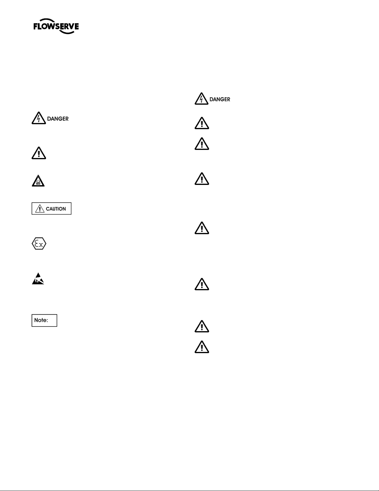
1.6.1 Summary of safety markings
These user instructions contain specific safety
markings where non-observance of an instruction
would cause hazards. The specific safety markings
are:
This symbol indicates electrical safety
instructions where non-compliance will involve a high
risk to personal safety or the loss of life
would affect personal safety.
This symbol indicates safety instructions where
non-compliance would affect personal safety and could
result in loss of life..
This symbol indicates “hazardous and toxic fluid”
safety instructions where non-compliance would affect
personal safety and could result in loss of life.
This symbol indicates safety instructions
where non-compliance will involve some risk to safe
operation and personal safety and would damage the
equipment or property.
This symbol indicates explosive atmosphere
zone marking according to ATEX. It is used in safety
instructions where non-compliance in the hazardous
area would cause the risk of an explosion.
This symbol is used in safety instructions to
remind not to rub non-metallic surfaces with a dry cloth;
ensure the cloth is damp. It is used in safety
instructions where non-compliance in the hazardous
area would cause the risk of an explosion.
This sign is not a safety symbol but indicates
an important instruction in the assembly process.
1.6.2 Personnel qualification and training
All personnel involved in the operation, installation,
inspection and maintenance of the unit must be
qualified to carry out the work involved. If the
personnel in question do not already possess the
necessary knowledge and skill, appropriate training and
instruction must be provided. If required the operator
may commission the manufacturer/supplier to provide
applicable training.
Always coordinate repair activity with operations and
health and safety personnel, and follow all plant safety
requirements and applicable safety and health laws
and regulations.
1.6.3 Safety action
This is a summary of conditions and actions to
prevent injury to personnel and damage to the
environment and to equipment. (For products used
in potentially explosive atmospheres section 1.6.4
also applies.)
NEVER DO MAINTENANCE WORK
WHEN THE UNIT IS CONNECTED TO POWER
GUARDS MUST NOT BE REMOVED WHILE
THE PUMP IS OPERATIONAL
DRAIN THE PUMP AND ISOLATE PIPEWORK
BEFORE DISMANTLING THE PUMP
The appropriate safety precautions should be taken
where the pumped liquids are hazardous.
FLUORO-ELASTOMERS (When fitted.)
When a pump has experienced temperatures over
250 ºC (482 ºF), partial decomposition of fluoroelastomers (eg Viton) will occur. In this condition these
are extremely dangerous and skin contact must be
avoided.
HANDLING COMPONENTS
Many precision parts have sharp corners and the
wearing of appropriate safety gloves and equipment is
required when handling these components. To lift
heavy pieces above 25 kg (55 lb) use a crane
appropriate for the mass and in accordance with
current local regulations.
THERMAL SHOCK
Rapid changes in the temperature of the liquid within
the pump can cause thermal shock, which can result in
damage or breakage of components and should be
avoided.
NEVER APPLY HEAT TO REMOVE IMPELLER
Trapped lubricant or vapour could cause an explosion.
HOT (and cold) PARTS
If hot or freezing components or auxiliary heating
supplies can present a danger to operators and
persons entering the immediate area action must be
taken to avoid accidental contact. If complete
protection is not possible, the machine access must be
limited to maintenance staff only, with clear visual
warnings and indicators to those entering the
immediate area. Note: bearing housings must not be
insulated and drive motors and bearings may be hot.
If the temperature is greater than 80°C (176 °F) or
below - 5 °C (23 °F) in a restricted zone, or excee ds
local regulations, action as above shall be taken.
Page 5 of 48 flowserve.com
Page 6
MARK 3 GROUP 4 USER INSTRUCTIONS ENGLISH 71569286 08-12
®
HAZARDOUS LIQUIDS
When the pump is handling hazardous liquids care
must be taken to avoid exposure to the liquid by
appropriate sitting of the pump, limiting personnel
access and by operator training. If the liquid is
flammable and/or explosive, strict safety procedures
must be applied.
Gland packing must not be used when pumping
hazardous liquids.
PREVENT EXCESSIVE EXTERNAL
PIPE LOAD
Do not use pump as a support for piping. Do not mount
expansion joints, unless allowed by Flowserve in
writing, so that their force, due to internal pressure, acts
on the pump flange.
NEVER RUN THE PUMP DRY
ENSURE CORRECT LUBRICATION
(See section 5, Commissioning, start-up, operation and
shutdown.)
START THE PUMP WITH OUTLET
VALVE PART OPENED
(Unless otherwise instructed at a specific point in the
user instructions.)
This is recommended to minimize the risk of
overloading and damaging the pump or motor at full or
zero flow. Pumps may be started with the valve further
open only on installations where this situation cannot
occur. The pump outlet control valve may need to be
adjusted to comply with the duty following the run-up
process. (See section 5, Commissioning start-up,
operation and shutdown.)
INLET VALVES TO BE FULLY OPEN
WHEN PUMP IS RUNNING
Running the pump at zero flow or below the
recommended minimum flow continuously will cause
damage to the pump and mechanical seal.
1.6.4 Products used in potentially explosive
atmospheres
Measures are required to:
• Avoid excess temperature
• Prevent build up of explosive mixtures
• Prevent the generation of sparks
• Prevent leakages
• Maintain the pump to avoid hazard
The following instructions for pumps and pump units
when installed in potentially explosive atmospheres
must be followed to help ensure explosion protection.
For ATEX Both electrical and non-electrical equipment
must meet the requirements of European Directive
94/9/EC. Always observe the regional legal Ex
requirements eg Ex electrical items outside the EU may
be required certified to other than ATEX eg IECEx, UL.
1.6.4.1 Scope of compliance
Use equipment only in the zone for which it is
appropriate. Always check that the driver, drive coupling
assembly, seal and pump equipment are suitably rated
and/or certified for the classification of the specific
atmosphere in which they are to be installed.
Where Flowserve has supplied only the bare shaft
pump, the Ex rating applies only to the pump. The party
responsible for assembling the ATEX pump set shall
select the coupling, driver and any additional equipment,
with the necessary CE Certificate/ Declaration of
Conformity establishing it is suitable for the area in which
it is to be installed.
The output from a variable frequency drive (VFD) can
cause additional heating affects in the motor and so, for
pumps sets with a VFD, the ATEX Certification for the
motor must state that it is covers the situation where
electrical supply is from the VFD. This particular
requirement still applies even if the VFD is in a safe
area.
DO NOT RUN THE PUMP AT
ABNORMALLY HIGH OR LOW FLOW RATES
Operating at a flow rate higher than normal or at a flow
rate with no back pressure on the pump may overload
the motor and cause cavitation. Low flow rates may
cause a reduction in pump/bearing life, overheating of
the pump, instability and cavitation/ vibration.
Page 6 of 48 flowserve.com
Page 7
MARK 3 GROUP 4 USER INSTRUCTIONS ENGLISH 71569286 08-12
®
Temperature class
1.6.4.2 Marking
An example of ATEX equipment marking is shown
below. The actual classification of the pump will be
engraved on the nameplate.
II 2 GD c IIC 135 ºC (T4)
Equipment Group
I = Mining
II = Non-mining
Category
2 or M2 = High level protection
3 = normal level of protection
Gas and/or Dust
G = Gas; D= Dust
c = Constructional safety
(in accordance with En13463-5)
Gas Group
IIA – Propane (typical)
IIB – Ethylene (typical)
IIC – Hydrogen (typical)
Maximum surface temperature (Temperature Class)
(See section 1.6.4.3.)
1.6.4.3 Avoiding excessive surface temperatures
ENSURE THE EQUIPMENT TEMPERATURE
CLASS IS SUITABLE FOR THE HAZARD ZONE
Pumps have a temperature class as stated in the ATEX
Ex rating on the nameplate. These are based on a
maximum ambient of 40 °C (104 °F); refer to Flowser ve
for higher ambient temperatures.
The surface temperature on the pump is influenced by
the temperature of the liquid handled. The maximum
permissible liquid temperature depends on the ATEX
temperature class and must not exceed the values in
the table that follows.
Maximum permitted liquid temperature for pumps
to EN13463-1
T6
T5
T4
T3
T2
T1
Maximum surface
temperature permitted
85 °C (185 °F)
100 °C (212 °F)
135 °C (275 °F)
200 °C (392 °F)
300 °C (572 °F)
450 °C (842 °F)
Temperature limit of
liquid handled
65 °C (149 °F) *
80 °C (176 °F) *
115 °C (239 °F) *
180 °C (356 °F) *
275 °C (527 °F) *
400 °C (752 °F) *
The temperature rise at the seals and bearings and due
to the minimum permitted flow rate is taken into
account in the temperatures stated.
The operator is responsible to ensure that the
specified maximum liquid temperature is not
exceeded.
Temperature classification “Tx” is used when the liquid
temperature varies and when the pump is required to be
used in differently classified potentially explosive
atmospheres. In this case the user is responsible for
ensuring that the pump surface temperature does not
exceed that permitted in its actual installed location.
If an explosive atmosphere exists during the
installation, do not attempt to check the direction of
rotation by starting the pump unfilled. Even a short run
time may give a high temperature resulting from
contact between rotating and stationary components.
Avoid mechanical, hydraulic or electrical overload by
using motor overload trips, temperature monitors or a
power monitor and make routine vibration monitoring
checks.
In dirty or dusty environments, make regular checks and
remove dirt from areas around close clearances, bearing
housings and motors.
Where there is any risk of the pump being run against a
closed valve generating high liquid and casing external
surface temperatures fit an external surface temperature
protection device.
1.6.4.4 Preventing the build up of explosive
mixtures
ENSURE THE PUMP IS PROPERLY FILLED
AND VENTED AND DOES NOT RUN DRY
Ensure the pump and relevant suction and discharge
pipeline system is totally filled with liquid at all times
during the pump operation, so that an explosive
atmosphere is prevented. In addition it is essential to
make sure that seal chambers, auxiliary shaft seal
systems and any heating and cooling systems are
properly filled.
If the operation of the system cannot avoid this
condition install an appropriate dry run protection
device (eg liquid detection or a power monitor).
To avoid potential hazards from fugitive emissions of
vapour or gas to atmosphere the surrounding area
must be well ventilated.
Page 7 of 48 flowserve.com
Page 8

MARK 3 GROUP 4 USER INSTRUCTIONS ENGLISH 71569286 08-12
®
1.6.4.5 Preventing sparks
To prevent a potential hazard from mechanical
contact, the coupling guard must be non-sparking.
To avoid the potential hazard from random induced
current generating a spark, the baseplate must be
properly grounded.
Avoid electrostatic charge: do not rub non-metallic
surfaces with a dry cloth; ensure cloth is damp.
or ATEX, the coupling must be selected to comply with
F
94/9/EC. Correct coupling alignment must be
maintained.
Additional requirement for metallic pumps on nonmetallic baseplates
When metallic components are fitted on a non-metallic
baseplate they shall be individual grounded.
1.6.4.6 Preventing leakage
The pump must only be used to handle liquids for
which it has been approved to have the correct
corrosion resistance.
Avoid entrapment of liquid in the pump and associated
piping due to closing of suction and discharge valves,
which could cause dangerous excessive pressures to
occur if there is heat input to the liquid. This can occur
if the pump is stationary or running.
Bursting of liquid containing parts due to freezing must
be avoided by draining or protecting the pump and
ancillary systems.
Where there is the potential hazard of a loss of a seal
barrier fluid or external flush, the fluid must be
monitored.If leakage of liquid to atmosphere can result
in a hazard, install a liquid detection device.
1.6.4.7 Maintenance to avoid the hazard
CORRECT MAINTENANCE IS REQUIRED TO
AVOID POTENTIAL HAZARDS WHICH GIVE A RISK
OF EXPLOSION
The responsibility for compliance with maintenance
instructions is with the plant operator.
To avoid potential explosion hazards during
maintenance, the tools, cleaning and painting materials
used must not give rise to sparking or adversely affect
the ambient conditions. Where there is a risk from
such tools or materials, maintenance must be
conducted in a safe area.
It is recommended that a maintenance plan and
schedule is adopted. (See section 6, Maintenance.
Page 8 of 48 flowserve.com
Page 9
MARK 3 GROUP 4 USER INSTRUCTIONS ENGLISH 71569286 08-12
®
1.7 Nameplate and warning labels
1.7.1 Nameplate
For details of nameplate, see the Declaration of
Conformity or separate documentation included with
these User Instructions
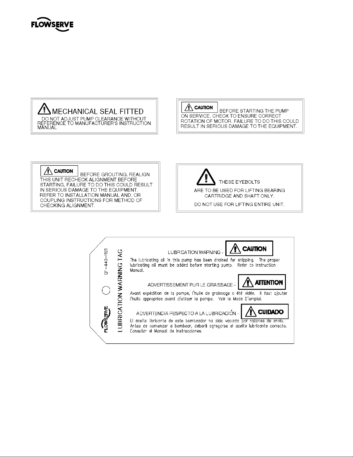
1.7.2 Safety labels
MECHANICAL SEAL WARNING ROTATION WARNING
P/N 2113931-001 P/N 2113932-001
GROUT WARNING LIFTING WARNING
P/N 2113934-001 P/N 9901701-001
LUBRICATION WARNING – QF-440-R01 (2124841)
Oil lubricated units only:
Page 9 of 48 flowserve.com
Page 10

MARK 3 GROUP 4 USER INSTRUCTIONS ENGLISH 71569286 08-12
®
1.8 Specific machine performance
For performance parameters see section 1.5, Duty
conditions. When the contract requirement specifies
these to be incorporated into User Instructions these
are included here. Where performance data has
been supplied separately to the purchaser these
should be obtained and retained with these User
Instructions if required.
capacity, pipework design and acoustic
characteristics of the building. The levels specified in
the table below are estimated and not guaranteed.
The dBA values are based on the noisiest ungeared
electric motors that are likely to be encountered.
They are Sound Pressure levels at 1 m (3.3 ft) from
the directly driven pump, for "free field over a
reflecting plane". For estimating L
sound power
wA
level (re 1 pW) add 14dBA to the sound pressure
1.9 Noise level
When pump noise level exceeds 85 dBA attention
must be given to prevailing Health and Safety
Legislation, to limit the exposure of plant operating
personnel to the noise. The usual approach is to
control exposure time to the noise or to enclose the
machine to reduce emitted sound. You may have
already specified a limiting noise level when the
value.
If a pump unit only has been purchased, for fitting
with your own driver, then the "pump only" noise
levels from the table should be combined with the
level for the driver obtained from the supplier. If the
motor is driven by an inverter, it may show an
increase in noise level at some speeds. Consult a
Noise Specialist for the combined calculation.
equipment was ordered, however if no noise
requirements were defined then machines above a
certain power level will exceed 85 dBA. In such
situations consideration must be given to the fitting of
an acoustic enclosure to meet local regulations.
For units driven by equipment other than
electric motors or units contained within enclosures,
see the accompanying information sheets and
manuals.
Pump noise level is dependent on a number of
factors, the type of motor fitted, the operating
Motor size
and speed
kW (hp)
<0.55(<0.75) 62 64 62 64 60 62 60 64
0.75 (1) 62 64 62 64 60 62 60 64
1.1 (1.5) 64 64 62 63 62 64 60 63
1.5 (2) 64 64 62 63 62 64 60 63
2.2 (3) 65 66 63 64 63 66 61 64
3 (4) 65 66 63 64 63 66 61 64
4 (5) 65 66 63 64 63 66 61 64
5.5 (7.5) 66 67 64 65 64 67 63 65
7.5 (10) 66 67 64 65 64 67 63 65
11(15) 70 71 68 69 68 71 67 69
15 (20) 70 71 68 69 68 71 67 69
18.5 (25) 71 71 69 71 69 71 68 70
22 (30) 71 71 69 71 69 71 68 70
30 (40) 73 73 71 73 71 73 70 72
37 (50) 73 73 71 73 71 73 70 72
45 (60) 76 76 74 76 74 76 72 75
55 (75) 76 76 74 76 74 76 72 75
75 (100) 77 77 75 77 75 77 73 76
90 (120) 77 78 75 78 75 78 73 76
110 (150) 79 80 77 80 77 78 75 78
150 (200) 79 80 77 80 77 78 76 78
200 (270) 85
300 (400) 87 90 85 86
1 The noise level of machines in this range will most likely be of values which require noise exposure control, but typical values are
inappropriate.
1 750 r/min 1 450 r/min 1180 r/min 980 r/min
Pump
only
Pump and
Typical sound pressure level LpA at 1 m reference 20 µPa, dBA
motor
87 83
Pump
only
Pump and
motor
85 81
Pump
only
Pump and
83
motor
83 80
85
Pump
only
82
Pump and
motor
82
84
Page 10 of 48 flowserve.com
Page 11
MARK 3 GROUP 4 USER INSTRUCTIONS ENGLISH 71569286 08-12
®
Note: For 880 and 720 r/min reduce 980 r/min values by 2 dBA.
2 TRANSPORT AND STORAGE
2.1 Consignment receipt and unpacking
Immediately after receipt of the equipment it must be
checked against the delivery/shipping documents for
its completeness and that there has been no damage
in transportation. Any shortage and/or damage must
be reported immediately to Flowserve Pump Division
and must be received in writing within one month of
receipt of the equipment. Later claims cannot be
accepted.
Check any crate, boxes or wrappings for any
accessories or spare parts that may be packed
separately with the equipment or attached to side
walls of the box or equipment.
Each product has a unique serial number. Check
that this number corresponds with that advised and
always quote this number in correspondence as well
as when ordering spare parts or further accessories.
2.2 Handling
Boxes, crates, pallets or cartons may be unloaded
using fork-lift vehicles or slings dependent on their
size and construction.
The pump should be lifted with suitably sized and
located slings. Do not use the shaft for lifting and take
special care to prevent the pump from rotating in the
slings due to unbalanced weight distribution.
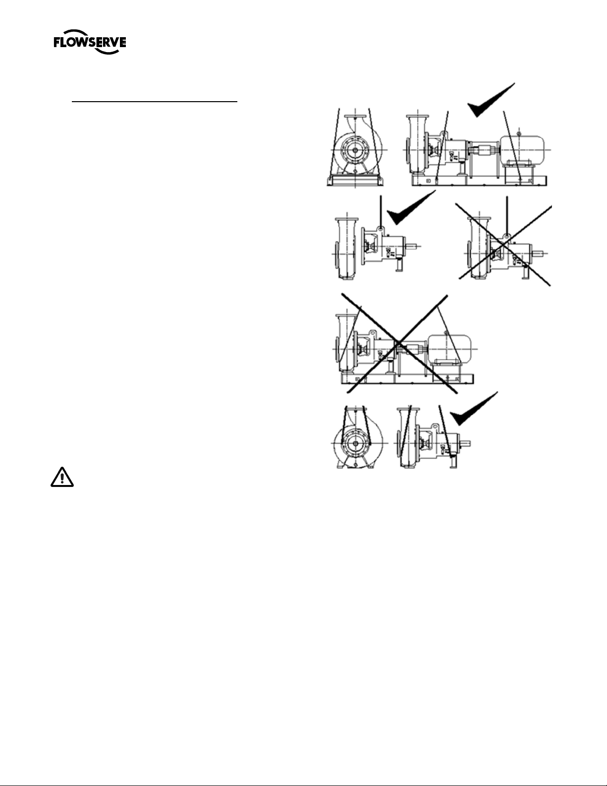
2.3 Lifting
A crane must be used for all pump sets or
components in excess of 25 kg (55 lb). Fully trained
personnel must carry out lifting, in accordance with
local regulations. The driver and pump weights are
recorded on the general arrangement drawing for the
specific project. The table of engineering data in
section 3.5 is for bare pump only and does not
include the weight of the base, driver or auxiliary
equipment.
The pump unit should be lifted as shown. Do not Use
the driver, bare shaft pump or component lifting
points to lift the complete machine.
Before lifting the driver alone, refer to the
manufacturer’s instructions
Page 11 of 48 flowserve.com
Page 12

MARK 3 GROUP 4 USER INSTRUCTIONS ENGLISH 71569286 08-12
®
2.4 Storage
2.4.1 Short-Term Storage
When it is necessary to store a pump for a short time
before it can be installed, place it in a dry, cool
location. Protect it thoroughly from moisture and
condensation. Protective flange covers should not be
removed until the pump is being installed.
Wrap the exposed portions of the shaft and coupling
to protect against sand, grit or other foreign matter.
Oil lubricated units should be lubricated (refer to
Section III) to protect the bearings. Grease
lubricated units are lubricated at the factory during
assembly. Turn the rotor over by hand at least once
a week to maintain a protective film on the bearing
components.
2.4.2 LONG-TERM STORAGE
More than precautions are required if long-term
storage in excess of 90 days from factory shipment is
unavoidable.
The internal surfaces of the pump should be sprayed
with a rust preventative such as a water soluble oil or
other suitable alternative. Particular attention should
be given to the impeller, wear plate and stuffing box.
An optional method of protection is to suspend bags
of desiccant material inside casing and completely
seal all openings from the surrounding atmosphere.
The stuffing box should be packed with clean, dry
rags. Use of this method requires that the casing be
initially free of liquid. The desiccant material should
be checked at regular intervals to ensure that it has
not absorbed excessive water vapour. A warning
instruction, advising that the desiccant must be
removed prior to installation should be wired to the
pump.
A rust inhibitor should be added to the lubricating oil
of oil lubricated units to give additional protection
without destroying the lubricating properties of the oil.
For specific recommendations, consult your
lubrication dealer. Grease lubricated units, which
can be identified by the grease fitting at each bearing
location, should be well lubricated prior to placing in
storage. Small amounts of additional grease should
be added at regular intervals during storage. Refer
to Section III for additional information related to
grease lubrication.
Storage of pumps in areas of high ambient vibration
should be avoided to prevent bearing damage due to
brinelling. The risk of such damage can be reduced
by frequent rotation of the shaft.
The pump half coupling and key should be removed
from the shaft, coated with rust preventative and
wrapped to prevent metal-to-metal contact. Exposed
surfaces of the pump shaft should be protected with
a rust preventative. All dismantled parts should be
wrapped and tagged according to pump serial
number and a record kept of their location.
Pumps covered with plastic
should not be stored in a cool environment
because resulting condensation can cause
rusting.
2.5 Recycling and end of product life
At the end of the service life of the product or its
parts, the relevant materials and parts should be
recycled or disposed of using an environmentally
acceptable method and in accordance with local
regulations. If the product contains substances that
are harmful to the environment, these should be
removed and disposed of in accordance with current
local regulations. This also includes the liquids
and/or gases that may be used in the "seal system"
or other utilities.
Make sure that hazardous substances are
disposed of safely and that the correct personal
protective equipment is used. The safety
specifications must be in accordance with the current
local regulations at all times.
3 PUMP DESCRIPTION
3.1 Configurations
Flowserve "MARK 3" pumps are single stage, end
suction centrifugal pumps specifically designed for
the chemical process industry and consequently are
ideally suited to many process fluids. A volute type
casing with integrally cast feet and top centerline
discharge nozzle is standard. The semi-open
impeller with rear pump-out vanes is designed for
high efficiency and prevents clogging. Sealing is
provided at the impeller to shaft fit to prevent
corrosion and thereby facilitate impeller removal.
The thrust bearing housing uses a threaded
adjustment that will permits precision bearing
alignment and impeller setting. The back pull-out
feature, typical of all MARK 3 pumps, permits quick
removal of the entire rotor/frame assembly without
disturbing the casing or driver.
The pump is sealed using non-asbestos packing in
the stuffing box, various mechanical seal designs as
specified by the customer may be installed at the
factory or retrofitted in the field.
All pumps are carefully inspected and prepared for
shipment. All exterior machined surfaces are coated
Page 12 of 48 flowserve.com
Page 13

MARK 3 GROUP 4 USER INSTRUCTIONS ENGLISH 71569286 08-12
®
with a rust preventative compound and openings are
provided with covers or plugs. Shaft packing, when
required, is shipped with the pump and should not be
installed until the pump is ready to run. Mechanical
seals, when provided, are factory installed and
adjusted prior to shipment. The axial impeller
running clearance is preset at the factory but should
be checked prior to final alignment in case of
tampering.
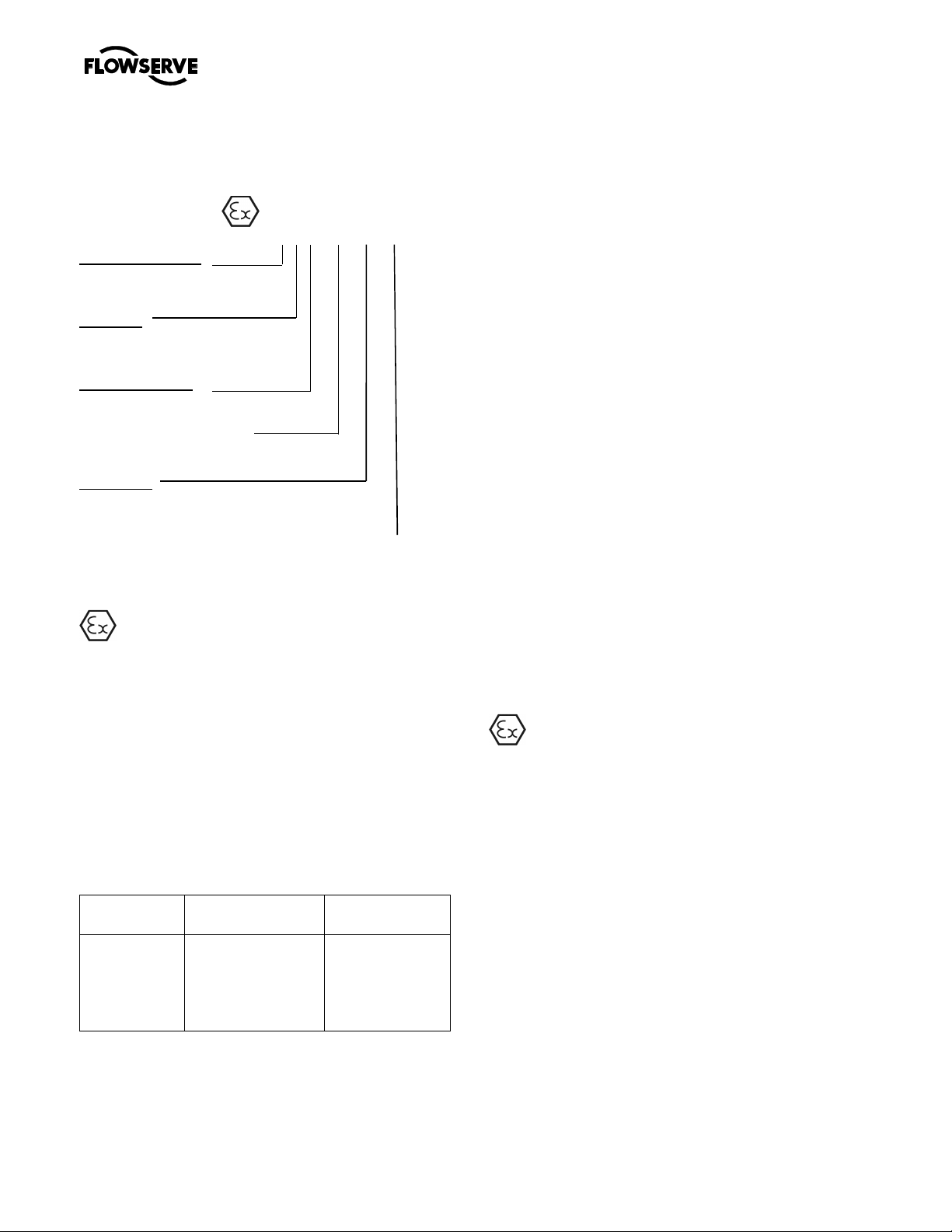
3.2 Name nomenclature
The pump size will be engraved on the nameplate.
The following example explains how the pump name
identifies the construction features and options.
4K10x6-18OP
Group size
Power end
Nominal suction branch size
Nominal discharge branch size
Nominal maximum impeller diameter
Open impeller
3.3 Design of major parts
3.3.1 Pump casing
The pump casing is a volute type casing with
integrally cast feet and top centerline discharge
nozzle. It is a one piece pressure retaining casting
with gasket connections to the stuffing box head and
the suction and discharge flanges.
3.3.2 Impeller
The impeller is semi-open design, keyed to the shaft
and secured with a contoured impeller nut. The
vanes of the impeller are Francis type.
3.3.3 Shaft
The large diameter stiff shaft, mounted on bearings,
has a keyed drive end.
3.3.4 Pump bearings and lubrication
Ball bearings are fitted as standard and may be
either oil or grease lubricated. Oil lubrication is only
available where the pump shaft is horizontal.
3.3.5 Bearing housing
For oil lubricated bearings, a bulls eye level gauge is
supplied. Constant level oilers can also be fitted. Two
grease nipples enable grease lubricated bearings to
be replenished between major service intervals.
3.3.6 Stuffing box housing
The stuffing box housing has a spigot (rabbet) fit
between the pump casing and bearing housing for
optimum concentricity. The design enables a
number of sealing options to be fitted.
3.3.7 Shaft seal
The mechanical seal(s), attached to the pump shaft,
seals the pumped liquid from the environment.
Gland packing may be fitted as an option.
3.3.8 Driver
The driver is normally an electric motor. Different
drive configurations may be fitted such as internal
combustion engines, turbines, hydraulic motors etc
driving via couplings, belts, gearboxes, drive shafts
etc.
3.3.9 Accessories
Accessories may be fitted when specified by the
customer.
3.4 Performance and operating limits
This product has been selected to meet the
specifications of your purchase order see section 1.5.
The following data is included as additional
information to help with your installation. It is typical,
and factors such as temperature, materials, and seal
type may influence this data. If required, a definitive
statement for your particular application can be
obtained from Flowserve.
3.4.1 Operating limits
Pumped liquid temperature limits up to+177 ºC (350 ºF)
Minimum ambient temperature -20 ºC (-4 ºF)
Maximum ambient temperature +50 ºC (122 ºF)
Maximum soft solids in suspension up to 7 % by volume
Maximum pump speed Refer to the nameplate
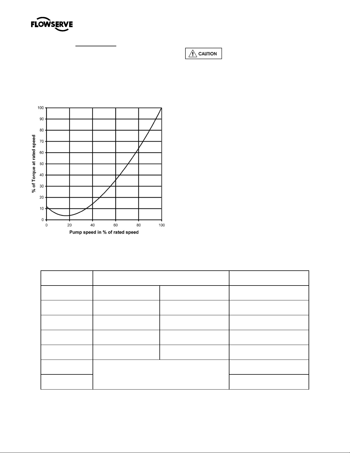
3.4.2 Speed torque curves
To bring a centrifugal pump up to rated speed, the
driver must be capable of providing more torque at
each speed than required by the pump. The margin
between the available and required torque affects the
time it takes the unit to reach full speed. If the torque
required by the pump exceeds the torque capability
of the drive at any run-up speed, the unit will not
accelerate to full speed. Normally, this is not a
problem with standard induction or synchronous
motors provided the proper voltage is supplied at the
motor.
For pumps started at shut valve conditions, 100
percent full speed torque can be calculated by using
the formula:
Torque (Nm) = 9545 Shutoff Power (kW)
r/min
Page 13 of 48 flowserve.com
Page 14
MARK 3 GROUP 4 USER INSTRUCTIONS ENGLISH 71569286 08-12
®
Torque (lbfx ft) = 5250 Shutoff Power (hp)
r/min
Torque required by the pump at any other speed
during start-up can be determined from the curve.
Note that the driver manufacturer usually bases 100
percent torque on the design power of the driver and
consequently the speed-torque curves should be
plotted in torque units (e.g. Nm) instead of
percentage torque to avoid confusion.
pressures shall be derated.
Do not conduct a hydro test on the
namplete pump set without the specific approval of
Flowserve. While the duty requirement will have been
covered, auxiliary items, flange drillings and suction
pressure limits may impose a reduced static and
dynamic pressure rating compared to that of the
pump casting rating itself.
Note: all flanges are ANSI 125 (Cast Iron or Ductile
Iron-flat faced) or ANSI 150 (Stainless-raised face)
unless otherwise stated. All flange facings on the
casings are 250 rms – circular finish
3.4.3 MAXIMUM WORKING PRESSURES -bar
(psi).
Above ambient temperature these maximum
CONSTRUCTION CAST IRON AND C.I.S.S. FITTED
TEMPERATURE
°C ( °F)
-30 to 38 (-20 to100) 10.3 (150) 10.3 (150) 13.8 (200)
65 (150) 10.3 (150) 9.7 (140) 13.8 (200)
95 (200) 10.3 (150) 9.3 (135) 13.4 (195)
120 (250) 10.3 (150) 9.0 (130) 12.6 (185)
150 (300)
UP TO 12”
DISCHARGE
Consult factory for applications in this range. Cast
iron not recommended due to thermal shock risks.
14 TO 16”
DISCHARGE
316,317L, WORTHITE, ETC.
175 (350) 11.0 (160)
STAINLESS STEEL
UP TO 16”
DISCHARGE
12.1 (175)
Page 14 of 48 flowserve.com
Page 15
MARK 3 GROUP 4 USER INSTRUCTIONS ENGLISH 71569286 08-12
®
3.5 Table Of Engineering Data
3.5.1 (GROUP 4 - LIQUID END)
ENGINEERING DATA
4K8x4-18OP
4K10X8-18OP
4K12X10-18OP
4K10X6-18OP
4K14X12-18OP
4K14X14-18OP
4K16X16-18OP
PUMP DATA
SUCTION DIAMETER mm (in.) 200 (8) 250 (10) 300 (12) 250 (10) 350 (14) 350 (14) 400 (16)
DISCHARGE DIAMETER mm (in.) 100 200 (8) 250 (10) 150 (6) 300 (12) 350 (14) 400 (16)
CASINGTHICK
NESS
C.I. mm (in.) 16 (0.63) 21 (0.82) 21 (0.82) 18 (0.69) 19 (0.75) 21 (0.82) 21 (0.82)
S.S.mm (in.) 12 (0.50) 16 (0.63) 18 (0.69) 14(0.56) 16 (0.63) 18 (0.69) 18 (0.69)
CASING TYPE SV DV SV DV-DUAL VOLUTE
GAUGE CONNECTION 1 / 2 NPT
DRAIN CONNECTION 3/4 NPT 1 NPT 1 - 1 / 4 NPT
NO. OF VANES 4 6 5
IMPELLER EYE AREA m2 (in.2)
0.020
(31.0)
0.036
(55.6)
0.043
(66.0)
0.029
(45.2)
0.076
(117)
0.083
(130)
0.108
(169)
MAX. SPHERE DIA. mm (in.) 28 (1.1) 56 (2.2) 68 (2.7) 48 (1.9) 97 (3.8) 41 (1.6) 41 (1.6)
WK2 kg•m2 (lb•ft.2)
PUMP WT. kg (lb.)
0.57
(13.6)
473
(1040)
1.00
(23.9)
555
(1220)
1.32
(31.3)
718
(1580)
0.83
(19.8)
644
(1420)
0.93
(22.0)
816
(1800)
1.57
(37.2)
902
(1990)
1.39
(33.0)
1021
(2250)
Max. BACK PULLOUT WT kg (lb.) 340 (750)
IMPELLER AXIAL mm (in.)
FRONT CLEARANCE
MAXIMUMTEM
PERATURE
NO COOLING
WITH COOLING
0.38/0.50
(0.015 /0.020)
120 °C (250 °F)
176 °C (350 °F)
STUFFING BOX DATA – CBS
O.D. SLEEVE mm (in.) 76.20 (3.000) 95.25 (3.750)
STUFFING BOX BORE mm (in.) 101.6 (4.000) 127.0 (5.000)
DEPTH OF BOX mm (in.) 99.0 (3.90) 122.2 (4.81)
PACKING SIZE (in.) 1 /2 X 1 /2 5 / 8 X 5 / 8
PACKING STD. 2L3
ARRANGEMENT ALT. 3L2
DISTANCE TO FIRST mm (in.)
OBSTRUCTION (gland)
Page 15 of 48 flowserve.com
130 (5.11) 107 (4.21)
Page 16

MARK 3 GROUP 4 USER INSTRUCTIONS ENGLISH 71569286 08-12
®
3.6 Table of Engineering Data
3.6.1 (GROUP 4 - FRAME DETAILS)
ENGINEERING DATA
4K8x4-18OP
4K10X8-18OP
4K12X10-18OP
4K10X6-18OP
4K14X12-18OP
SHAFT AND BEARING DATA
Dia. at Impeller mm (in.)
Dia. Under Sleeve mm (in.) 66.68 (2.625) 82.55 (3.250)
Dia. Between Brgs mm (in.) 114.3 (4.50)
Dia. at Coupling mm (in.) 73.03 (2.875)
Line Bearing 6220
Thrust Bearing 7318 BUA (PAIRED BACK-TO-BACK)
BEARING SPAN mm (in.) 293.4 (11.55)
Nom. Impeller Overhang mm (in.) 312.2 (12.29)
B10 Bearing Life MINIMUM 3 YEARS
Oil Sump Capacity* l (US gal.)
* Standard construction is oil lubrication.
50.8 (2.000) 69.9 (2.750)
5 (1.3)
4K14X14-18OP
4K16X16-18OP
Page 16 of 48 flowserve.com
Page 17

MARK 3 GROUP 4 USER INSTRUCTIONS ENGLISH 71569286 08-12
®
IRON CASING
3.7 Materials of Construction
3.7.1 (LIQUID END)
BASIC
CONSTRUCTION
Casing,
Stuff Box Head
Impeller
Impeller Nut
Throat Bushing
Shaft Sleeve
ALL IRON
AIF
ASTM A48
CL35A
ASTM A48
CL30A
ASTM A743
CG3M
ASTM A743
CF8M
ASTM A743
CG3M *
ALL 316 SS
(SS)
ASTM A743
CF8M
ASTM A743
CF8M
ASTM A743
CG3M
ASTM A743
CF8M
ASTM A743
CG3M *
SS FITTED
(SSF)
ASTM A48
CL35A
ASTM A743
CF8M
ASTM A743
CG3M
ASTM A743
CF8M
ASTM A743
CG3M *
317L SS CD4MCUN
ASTM A743
CG3M
ASTM A743
CG3M
ASTM A743
CG3M
ASTM A743
CG3M
ASTM A743
CG3M *
ASTM A890
CD4MCUN
ASTM A890
CD4MCUN
ASTM A890
CD4MCUN
ASTM A890
CD4MCUN
ASTM A890
CD4MCUN
WORTHITE
W
ASTM A743
CN7MS
ASTM A743
CN7MS
ASTM A743
CN7M
ASTM A743
CN7M
ASTM A743
CN7M
Shaft AISI 1045 AISI 1045 AISI 1045 AISI 1045 AISI 1045 AISI 316
Gland Halves
ASTM A743
CF8M
ASTM A743
CF8M
ASTM A743
CF8M
ASTM A743
CN7M
ASTM A890
CD4MCUN
ASTM A743
CN7M
Pipe Plugs (Liquid End) C.I. AISI 316 C.I. A-20 A-20 A-20
Gland Studs And Nuts AISI 316
Impeller Key AISI 316
Packing Synthetic Fibre
Seal Cage Halves ASTM A743 CG8M
Gaskets Synthetic Fibre
O-Rings (Liquid End) BUNA-N (120o C MAX.)**
Misc. Fastners,Parts Steel
* Nickel-Chrome-Boron Coated, except for units with mechanical seals.
** Viton will be used for all applications operating above 120oC.
ASTM A743
CN7M
Page 17 of 48 flowserve.com
Page 18
MARK 3 GROUP 4 USER INSTRUCTIONS ENGLISH 71569286 08-12
®
4 INSTALLATION
Equipment operated in hazardous locations
must comply with the relevant explosion protection
regulations. See section 1.6.4, Products used in
potentially explosive atmospheres.
4.1 Location
The pump should be located to allow room for
access, ventilation, maintenance and inspection with
ample headroom for lifting and should be as close as
practicable to the supply of liquid to be pumped.
Allow sufficient room to facilitate the back pull-out
feature on V-belt driven units.
Refer to the general arrangement drawing for the
pump set.
4.2 Part assemblies
Motors may be supplied loose on MARK 3 pumps,
typically on frame sizes 400 and above. It is the
responsibility of the installer to ensure that the motor
is assembled to the pump and lined up as detailed in
section 4.5.2.
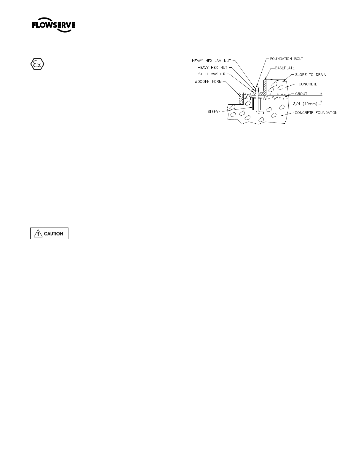
4.3 Foundation
The foundation may consist of any
material that will afford permanent, rigid support to
the full area of the pump or driver supporting
member. It should be of sufficient size and mass to
absorb expected strains and shocks that may be
encountered in service. Concrete foundations built
on solid ground are desirable. Use a concrete grade
with a strength of approximately 20MPa (2900 PSI).
The purpose of foundation bolts is to anchor the
pump unit securely to the foundation such that the
foundation and pump assembly become a single
structural unit. High strength steel foundation bolts
(SAE Gr. 5 or equal) of the specified diameter should
be located according to the elevation drawing
provided. Each bolt should be surrounded by a pipe
sleeve which is two or three times the diameter of the
bolt. The sleeves should be securely anchored and
designed to allow the bolts to be moved to conform
with the holes in the baseplate. The bolts should be
sufficiently long to allow for wedges or shims or
levelling nuts under the baseplate, and a washer,
heavy hex nut and hex jam nut for retention. Since
baseplate levelling is performed after the foundation
has cured, it is best to use extra long bolts that can
be shortened after the installation is complete.
4.4 Baseplate installation
Position the baseplate and pump next to the
foundation and clean the foundation surface
thoroughly. Remove the rag packing from the pipe
sleeves and place wedges or ships as close to the
foundation bolts as possible. These may be omitted
if a jacking nut on the foundation anchor bolts is
preferred for levelling.
Remove the flange covers and check inside the
pump nozzles for cleanliness. Kerosene is
recommended as the best solvent for removing
factory applied rust preventative. Ensure that all
traces of rust preventative are removed from the
discharge and suction flange faces, the exposed
shafting and all coupling surfaces. Flush the pump
internals of any rust preventative applied for longterm storage.
Lift the baseplate assembly, remove the shipping
skids and clean the underside of the baseplate.
Position the baseplate over the foundation and lower
the unit over the foundation bolts and onto the
wedges, shims or jacking nuts.
a) Level the pump baseplate assembly. If the
baseplate has machined coplanar mounting
surfaces, these machined surfaces are to be
referenced when leveling the baseplate. This
may require that the pump and motor be
removed from the baseplate in order to reference
the machined faces. If the baseplate is without
machined coplanar mounting surfaces, the pump
and motor are to be left on the baseplate. The
proper surfaces to reference when leveling the
pump baseplate assembly are the pump suction
and discharge flanges. DO NOT stress the
baseplate.
b) Do not bolt the suction or discharge flanges of
the pump to the piping until the baseplate
foundation is completely installed. If equipped,
use leveling jackscrews to level the baseplate. If
Page 18 of 48 flowserve.com
Page 19

MARK 3 GROUP 4 USER INSTRUCTIONS ENGLISH 71569286 08-12
®
jackscrews are not provided, shims and wedges
should be used. (See Figure 4-5.) Check for
levelness in both the longitudinal and lateral
directions. Shims should be placed at all base
anchor bolt locations. Do not rely on the bottom
of the baseplate to be flat. Standard baseplate
bottoms are not machined and it is not likely that
the field mounting surface is flat.
c) After leveling the baseplate, tighten the anchor
bolts. If shims were used, make sure that the
baseplate was shimmed near each anchor bolt
before tightening. Failure to do this may result in
a twist of the baseplate, which could make it
impossible to obtain final alignment.
d) Check the level of the baseplate to make sure
that tightening the anchor bolts did not disturb
the level of the baseplate. If the anchor bolts did
change the level, adjust the jackscrews or shims
as needed to level the baseplate.
e) Continue adjusting the jackscrews or shims and
tightening the anchor bolts until the baseplate is
level.
f) Check initial alignment. If the pump and motor
were removed from the baseplate proceed with
step g) first, then the pump and motor should be
reinstalled onto the baseplate using Flowserve’s
factory preliminary alignment procedure as
described in section 4.5, and then continue with
the following. As described above, pumps are
given a preliminary alignment at the factory. This
preliminary alignment is done in a way that
ensures that, if the installer duplicates the factory
conditions, there will be sufficient clearance
between the motor hold down bolts and motor
foot holes to move the motor into final alignment.
If the pump and motor were properly reinstalled
to the baseplate or if they were not removed from
the baseplate and there has been no transit
damage, and also if the above steps where done
properly, the pump and driver should be within
0.38 mm (0.015 in.) FIM (Full Indicator
Movement) parallel, and 2.5 mm/m
(0.0025 in./in.) FIM angular. If this is not the
case, first check to see if the driver mounting
fasteners are centered in the driver feet holes. If
not, re-center the fasteners and perform a
preliminary alignment to the above tolerances by
shimming under the motor for vertical alignment,
and by moving the pump for horizontal
alignment.
g) Grout the baseplate. A non-shrinking grout
should be used. Make sure that the grout fills the
area under the baseplate. After the grout has
cured, check for voids and repair them.
Jackscrews, shims and wedges should be
removed from under the baseplate at this time. If
they were to be left in place, they could rust,
swell, and cause distortion in the baseplate.
h) Run piping to the suction and discharge of the
pump. There should be no piping loads
transmitted to the pump after connection is
made. Recheck the alignment to verify that there
are no significant loads.
Check the impeller axial clearance and that the rotor
turns freely by hand.
Note: Grout is not poured until an initial
alignment of the pump and driver has been
performed. See section 4.5
4.5 Initial alignment
The purpose of factory alignment is to ensure that the
user will have sufficient clearance in the motor holes
for final job-site alignment. To achieve this, the
factory has designed the mounting holes with
additional clearance to allow the pump to be aligned
in the horizontal plane to the motor, There should be
at least 1/16 clearance around the bolt. The coupling
has been designed to have some overhang of the
coupling hub (in most cases 1 or both hubs may be
overhung between 0.0 and 3 mm (0 and 0.12 in)
unless otherwise stated. This procedure ensures that
there is sufficient clearance in the motor holes for the
customer to field align the motor to the pump, to zero
tolerance. This philosophy requires that the customer
be able to place the base in the same condition as
the factory. Thus the factory alignment will be done
with the base sitting in an unrestrained condition on a
flat and level surface. This standard also emphasizes
the need to ensure the shaft spacing is adequate to
accept the specified coupling spacer.
Page 19 of 48 flowserve.com
Page 20

MARK 3 GROUP 4 USER INSTRUCTIONS ENGLISH 71569286 08-12
®
The factory alignment procedure is summarized
below:
a) The baseplate is placed on a flat and level
workbench in a free and unstressed position.
b) The baseplate is leveled as necessary. Leveling
is accomplished by placing shims under the rails
of the base at the appropriate anchor bolt hole
locations. Levelness is checked in both the
longitudinal and lateral directions.
c) The pump is put onto the baseplate, aligned and
leveled. The rear foot piece under the bearing
housing is adjustment as necessary by adding or
removing shims [3126.1] between the foot piece
and the bearing housing or at the baseplate.
d) The motor and appropriate motor mounting
hardware is placed on the baseplate and the
motor is checked for any planar soft-foot
condition. If any is present it is eliminated by
shimming.
e) The motor is fastened in place by tightening two
diagonal motor mounting bolts.
f) The spacer coupling gap is verified. As indicated
the gap may be adjusted to ensure adequate
axial bolt clearance.
g) The parallel and angular vertical alignment is
made by shimming under the motor.
h) The pump and motor shafts are then aligned
horizontally, both parallel and angular, by moving
the pump to the fixed motor. The pump feet are
tightened down.
i) Both horizontal and vertical alignment is again
final checked as is the coupling spacer gap.
See section 4.8, Final shaft alignment.
4.5.1 Thermal expansion
The pump and motor will normally
have to be aligned at ambient temperature and
should be corrected to allow for thermal expansion at
operating temperature. In pump installations
involving high liquid temperatures, the unit should be
run at the actual operating temperature, shut down
and the alignment checked immediately.
4.5.2 Alignment methods
Ensure pump and driver are isolated
electrically and the half couplings are disconnected.
The alignment MUST be checked.
Although the pump will have been aligned at the
factory it is most likely that this alignment will have
been disturbed during transportation or handling. If
necessary, align the motor to the pump, not the pump
to the motor.
4.5.2.1 Direct Driven Units
The importance of accurate alignment of pump
and driver shafts cannot be overemphasized.
IMPROPER ALIGNMENT IS THE PRIMARY
CAUSE OF VIBRATION PROBLEMS AND
REDUCED BEARING LIFE.
A flexible coupling is used to compensate for slight
changes in alignment that occur during normal
operation and is not used to correct for installation
errors. Install the pump and driver half couplings in
accordance with the coupling manufacturer's
instructions. Note that the coupling hub faces are not
always mounted flush with the ends of the shafts.
Place the driver on the baseplate such that the
correct spacing is obtained between the two half
couplings. In the case of electric motors, such as
those with sleeve bearings, it may be necessary to
run the motor to establish the rotor magnetic center.
Consult the manufacturer's instruction manual for
details.
The purpose of the alignment procedure is to ensure
that the pump and driver shafts are in parallel and
angular alignment under the normal operating
conditions of load and temperature.
When the pump coupling and driver are assembled
at the factory, the units are aligned prior to shipment.
However, baseplates can be sprung or distorted
during shipment or installation and the alignment
must be checked before the unit is put in service. The
coupling spacer must be removed to make this
check.
For pumps and drivers that operate at different
temperatures compensation must be made at the
initial alignment stage (when the units are at the
same temperature) to allow for thermal expansion
during operation. Consult the instruction manual
supplied with the driver for the manufacturer's
recommendations.
Shaft alignment is greatly simplified by the use of a
dial indicator, or with extension rods and a magnetic
base. Before taking readings, ensure that the pump
and driver mounting bolts are secure, and that the
thrust bearing housing is properly aligned in the
bearing frame or cartridge
Page 20 of 48 flowserve.com
Page 21
MARK 3 GROUP 4 USER INSTRUCTIONS ENGLISH 71569286 08-12
®
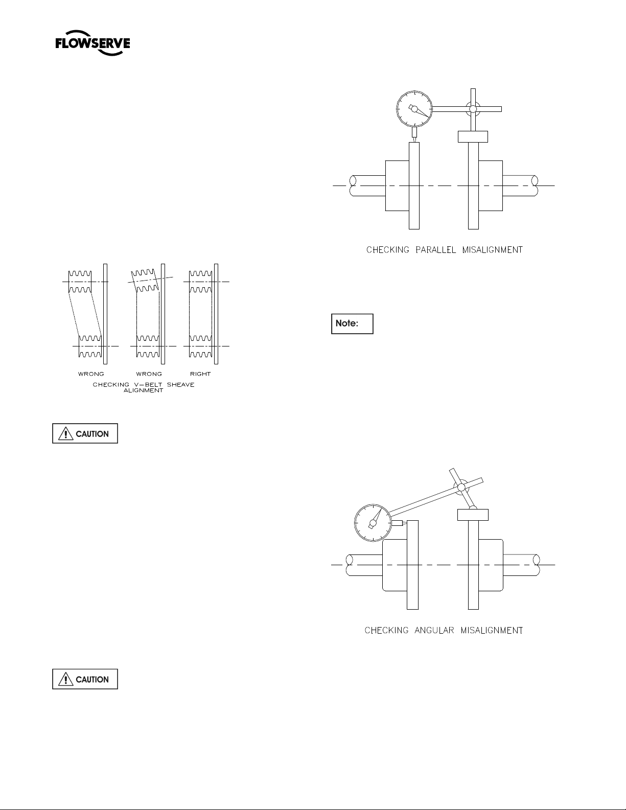
4.5.2.2 V-Belt Drive Units:
Check that both sheaves are free of grease, rust,
nicks or burrs. Install the correct size sheave on the
pump shaft and locate the sheave axially to minimize
overhang. Re-check the impeller axial clearance and
ensure that the pump is properly secured to the
baseplate. Install the driver on the adjustable base
provided and install the driver sheave in line with the
pump sheave. Ensure that the sheaves are tight on
the shafts. With a dial indicator, check the runout on
the periphery and face of each sheave to ensure that
each is running true. Tighten the adjustable base and
check that the driver rotation in the correct direction
and that vibration levels are not unacceptable.
Checking V-Belt Sheave Alignment
Before starting the driver, refer to the
manufacturer’s instruction manual. The correct
rotation of the pump shaft is marked on the pump
casing or frame.
Check that all belts making up one drive set have
matched code numbers. Loosen the adjustable base
and install the belts in their proper grooves. Adjust
the center distance between the sheaves to obtain
proper belt tension. Check the alignment of the pump
and driver sheaves with a taught string or straight
edge. For proper alignment and the sheave faces
must be parallel to each other and in line.
Adjustments are made by slackening the belts,
moving and retightening the drive or driver sheave,
and repeating the above procedure.
When the sheaves are aligned that the shafts rotate
freely by hand and install safety guard.
Belt drives must not be used in ATEX
Potentially explosive environments; refer to
Flowserve.
4.5.3 Parallel Alignment:
Mount the magnetic base on the pump half coupling
hub, either the face or O.D. as shown in the sketch.
Place the dial indicator button on the outside
diameter of the driver half coupling hub.
The length of extension rods should be kept
at a minimum to reduce deflection.
Rotate the pump shaft and record the dial reading at
the top, bottom and each side. Correct the parallel
alignment by adding or removing shims under the
driver and/or moving the driver horizontally. Repeat
this procedure until the maximum total indicator
reading (T.I.R.) is within 0.08 mm (0.003 inch.)
4.5.4 Angular Alignment:
Mount the magnetic base mounted on the pump half
coupling hub, either face or O.D. as shown. Move the
dial indicator button to indicate on the face of the
driver half coupling hub as close to the outside
diameter as possible. When convenient the indicator
can be placed on the inside face to keep spans short.
Turn both shafts 360° and record the dial readings at
90° intervals. Adjust the shims under the motor as
Page 21 of 48 flowserve.com
Page 22

MARK 3 GROUP 4 USER INSTRUCTIONS ENGLISH 71569286 08-12
®
required and repeat the procedure until the angular
alignment is within 0.0005 mm (T.I.R.) per mm
(0.0005 in. per in.) of maximum hub diameter.
Repeat the checks on parallel and angular alignment,
ensuring the mounting bolts are secure, until the unit
is properly aligned. Note that correction in one
direction may affect the alignment in another
direction. Re-check the gap between the coupling
hubs.
If any difficulty is encountered in achieving the
recommended alignment tolerances, the run-out of
the pump and driver shafts and each coupling hub
diameter and face should be checked. Occasionally,
due to practical and unavoidable manufacturing
tolerance build-up associate with the pump, coupling
and driver, it may be necessary to match up the two
coupling hubs in the most advantageous relative
angular position in order to achieve an acceptable
alignment.
Do not install the coupling spacer or sleeve until
grouting is complete and cured and the alignment is
re-checked.
When the electric motor has sleeve bearings it is
necessary to ensure that the motor is aligned to run
on its magnetic centreline. A button (screwed into
one of the shaft ends) is normally fitted between the
motor and pump shaft ends to fix the axial position.
If the motor does not run in its
magnetic centre the resultant additional axial force
may overload the pump thrust bearing.
4.5.5 Check for soft foot
This is a check to ensure that there is no undue
stress on the driver holding down bolts; due to nonlevel baseplate or twisting. To check, remove all
shims and clean surfaces and tighten down driver to
the baseplate. Set a dial indicator as shown in
sketch and loosen off the holding down bolt while
noting any deflection reading on the dial test Indicator
- a maximum of 0.05 mm (0.002 in.) is considered
acceptable but any more will have to be corrected by
adding shims. For example, if the dial test indicator
shows the foot lifting 0.15 mm (0.006 in.) then this is
the thickness of shim to be placed under that foot.
Tighten down and repeat the same procedure on all
other feet until all are within tolerance.
Complete piping as below and see sections
4.8, Final shaft alignment check up to and including
section 5, Commissioning, start-up, operation and
shutdown before connecting driver and checking
actual rotation.
4.6 Grouting
The purpose of grouting is to provide rigid support to
the pump and driver by increasing the structural
rigidity of the baseplate and making it an integral
mass with the foundation. Grouting should only be
completed after baseplate has been levelled (4.4)
and initial pump alignment (4.5).
Clean the roughed foundation surface and build a
wooden form around the baseplate. For initial
grouting forms should be placed to isolate shims and
levelling nuts. The foundation surface should be
thoroughly saturated with water before grouting. A
typical mixture for grouting-in a pump base is
composed of one part pure Portland cement and two
parts of clean building sand with sufficient water to
provide the proper consistency. The grout should
flow freely but not be so wet as to cause the sand
and cement to separate.
Thoroughly puddle the grout while pouring to
eliminate air pockets and low spots. Pour sufficient
grouting to ensure that the bottom surface of the
baseplate is completely submerged. Do not fill
isolated areas around the shims or levelling nuts.
Once the grout has set sufficiently, remove the
wooden forms and finish off the sides and top as
desired. At the same time, roughen the grout surface
inside the baseplate. Cover with wet burlap and
allow the grout to cure for at least 40 hours.
After grouting has cured, shims and levelling nuts
should be removed or backed off. Tighten down
baseplate to the new grout to put bolts in tension and
ensure rigidity of structure. Install jam nuts and cut
the bolts to the desired length. Finish grouting
isolated areas. Fill the baseplate including pump and
driver support pedestals with concrete. Trowel and
slope the surface to give suitable drainage.
Page 22 of 48 flowserve.com
Page 23

MARK 3 GROUP 4 USER INSTRUCTIONS ENGLISH 71569286 08-12
®
4.7 Piping
Maximum forces and moments allowed on the pump
flanges vary with the pump size and type. To
minimize these forces and moments that may, if
Protective covers are fitted to the pipe
connections to prevent foreign bodies entering during
transportation and installation. Ensure that these
covers are removed from the pump before
connecting any pipes.
4.7.1 Suction and discharge pipework
In order to minimize friction losses and hydraulic
noise in the pipework it is good practice to choose
pipework that is one or two sizes larger than the
pump suction and discharge. Typically main
pipework velocities should not exceed 2 m/s (6 ft/sec)
suction and 3 m/s (9 ft/sec) on the discharge.
excessive, cause misalignment, hot bearings, worn
couplings, vibration and the possible failure of the
pump casing, the following points should be strictly
followed:
• Prevent excessive external pipe load
• Never draw piping into place by applying force to
pump flange connections
• Do not mount expansion joints so that their force,
due to internal pressure, acts on the pump flange
The table in 4.7.2 summarizes the maximum forces
and moments allowed on MARK 3 Group 4 pump
casings. Refer to Flowserve for other configurations.
Take into account the available NPSH that must be
higher than the required NPSH of the pump.
Ensure piping and fittings are flushed
before use.
Never use the pump as a support for
piping.
Ensure piping for hazardous liquids is arranged
to allow pump flushing before removal of the pump.
4.7.2 Maximum forces and moments allowed on MARK 3, Group 4 pump flanges
Introduction: Flowserve Mark 3, Group 4 pumps are larger than those contained in ANSI/HI 9.6.2 and have been
designed around the FRBH process pump. API 610 has been used as a reference for these pumps to establish the
allowable forces and moments. Typically values are 2X API. The values shown in the table 4.7.2.2 are based on
pumps mounted on grouted baseplates. These values should be factored based on material of construction and
temperature. The table 4.7.2.1 has been adopted from Mark 3 manual (PCN 71569102) that uses data from
ANSI/HI 9.6.2.6.
Table 4.7.2.1: Casing Material Correction Factors
Material Group No.
1.0 2.2 2.8 3.8 3.17 Ti
Temp. °C Temp °F CI/DI 316/317L CD4MCU Hast. C Wort h/A20 Titanium
-29 -20 0.89 1.00 1.00 1.00 0.83 0.89
38 100 0.89 1.00 1.00 1.00 0.83 0.89
93 200 0.78 0.86 1.00 1.00 0.72 0.86
150 300 0.73 0.78 0.92 1.00 0.65 0.81
Page 23 of 48 flowserve.com
Page 24

MARK 3 GROUP 4 USER INSTRUCTIONS ENGLISH 71569286 08-12
®
Table 4.7.2.2
Maximum forces (F) in N (lbf) and moments (M) in Nm (lbf•ft)
Pump Size
Mx
4K8x4x18
4K10x6x18
4K10x8x18
4K12x10x18
4K14x12x18
4K14x14x18
4K16x16x18
Notes:
1) F = External force (tension or compression) M = External moment, clockwise or counter-clockwise
2) Forces and moments may be applied simultaneously in any direction
3) Correct values by material factor
4) Higher loads may be applicable, if direction and magnitude of individual loads are known, but these need written approval from Flowserve
5) Pumps must be on rigid foundations and baseplates must be fully grouted
6) Pump/baseplate should not used as pipe anchor. Expansion joints must be properly tied
7) The pump mounting bolt torques specified must be used to prevent relative movement between the pump casing and baseplate. (See
section 6.6, Fastener torques.) The bolt material must have a minimum yield strength of 600 N/mm
3530
(2600)
10040
(7400)
10040
(7400)
12200
(9000)
12740
(9400)
12740
(9400)
14640
(10800)
My
1760
(1300)
4880
(3600)
4880
(3600)
5960
(4400)
6240
(4600)
6240
(4600)
7320
(5400)
4.7.3 Suction piping
a) The inlet pipe should be one or two sizes larger
than the pump inlet bore and pipe bends should
be as large a radius as possible.
b) Pipework reducers should have a maximum total
angle of divergence of 15 degrees.
c) On suction lift the piping should be inclined up
towards the pump inlet with eccentric reducers
Suction Discharge
Mz Fx Fy Fz Mx My Mz Fx Fy Fz
2580
(1900)
7200
(5600)
7200
(5600)
9220
(6800)
9500
(7000)
9500
(7000)
10840
(8000)
4890
(1100)
13340
(3000)
13340
(3000)
16000
(3600)
16900
(4000)
16900
(4000)
20460
(4600)
3780
(850)
10680
(2400)
10680
(2400)
13340
(3000)
14240
(3200)
14240
(3200)
16900
(3800)
3100
(700)
8900
(2000)
8900
(2000)
10680
(2400)
11560
(2600)
11560
(2600)
13340
(1500)
1330
(980)
4600
(3400)
7060
(5200)
10040
(7400)
12200
(9000)
12740
(9400)
14640
(10800)
680
(500)
2360
(1740)
3520
(2600)
4880
(3600)
5960
(4400)
6240
(4600)
7320
(5400)
2
(87 000 lb/in.2)
1000
(740)
3560
(2600)
5160
(3800)
7600
(5600)
9220
(7200)
9500
(7000)
10840
(8000)
1420
(320)
4980
(1120)
7560
(1700)
10680
(2400)
13340
(3000)
14240
(3200)
16900
(3800)
1160
(260)
4100
(920)
6220
(1400)
8900
(2000)
10680
(2400)
11560
(2600)
13340
(3000)
d) On positive suction, the inlet piping must have a
constant fall towards the pump.
e) Flow should enter the pump suction with uniform
flow, to minimize noise and wear. This is
particularly important on large or high-speed
pumps that should have a minimum of four
diameters of straight pipe on the pump suction
between the elbow and inlet flange. See section
10.3, Reference 1 for more detail.
1780
(400)
6220
(1400)
9780
(2200)
13340
(3000)
16000
(3600)
17800
(4000)
20460
(4600)
incorporated to prevent air locks.
Page 24 of 48 flowserve.com
Page 25

MARK 3 GROUP 4 USER INSTRUCTIONS ENGLISH 71569286 08-12
®
f) Inlet strainers, when used, should have a net
`free area' of at least three times the inlet pipe
area.
g) Do not install elbows at an angle other than
perpendicular to the shaft axis. Elbows parallel
to the shaft axis will cause uneven flow.
h) Except in unusual circumstances strainers are
not recommended in inlet piping. If considerable
foreign matter is expected a screen installed at
the entrance to the wet well is preferable.
i) Fitting an isolation valve will allow easier
maintenance.
j) Never throttle pump on suction side and never
place a valve directly on the pump inlet nozzle.
4.7.4 Discharge piping
A non-return valve should be located in the discharge
pipework to protect the pump from excessive back
pressure and hence reverse rotation when the unit is
stopped.
Pipework reducers should have a maximum total
angle of divergence of 15 degrees. Fitting an
isolation valve will allow easier maintenance.
4.7.5 Auxiliary piping
4.7.5.1 Drains
Pipe pump casing drains and gland leakage to a
convenient disposal point.
4.7.5.2 Pumps fitted with gland packing
It is required that a clean water flush be provided to
the packing to provide lubrication and to prevent the
ingress of air. When the product is clean and free of
solids this can be achieved with a supply from the
pump discharge volute to the stuffing box (Plan 11).
A control valve or orifice may be fitted in the line to
enable the pressure to the gland to be controlled.
If the pumped liquid is dirty and cannot be used for
sealing, a separate clean compatible liquid supply to
the gland at a pressure equal to the estimated
stuffing box pressure, Ps (psig).
Ps = + Suction Pressure0.6 x TDH X S.G.
2.31
TDH = total developed head at shut valve (feet)
S.G. = Specific Gravity of pump liquid
Suction Pressure = maximum suction pressure
corrected for specific gravity (psig).
4.7.5.3 Pumps fitted with mechanical seals
Single seals requiring re-circulation will normally be
provided with the auxiliary piping from pump casing
already fitted.
If the seal requires an auxiliary quench then a
connection must be made to a suitable source of
liquid flow, low pressure steam or static pressure
from a header tank. Recommended pressure is 0.35
bar (5 psi) or less. Check General arrangement
drawing.
Special seals may require different auxiliary piping to
that described above. Consult separate User
Instructions and/or Flowserve if unsure of correct
method or arrangement.
For pumping hot liquids, to avoid seal damage, it is
recommended that any external flush/cooling supply
be continued after stopping the pump.
4.7.6 Final checks
Check the tightness of all bolts in the suction and
discharge pipework. Check also the tightness of all
foundation bolts.
4.8 Final shaft alignment check
After connecting piping to the pump, rotate the shaft
several times by hand to ensure there is no binding
and all parts are free.
The baseplate should be levelled and grouted by this
stage.
Recheck the coupling alignment, as previously
described, to ensure no pipe strain. If pipe strain
exists, correct piping.
a) Mount and level pump if appropriate. Level the
pump by putting a level on the discharge flange.
It may be necessary to adjust the bearing frame
foot by adding or deleting shims [3126.1]
between the foot piece and the bearing housing
(or baseplate).
b) Check initial alignment. If pump and driver have
been remounted or the specifications given
below are not met, perform an initial alignment as
described in section 4.5. This ensures there will
be sufficient clearance between the motor hold
down bolts and motor foot holes to move the
motor into final alignment. The pump and driver
should be within 0.38 mm (0.015 in.) FIM (full
indicator movement) parallel, and 2.5 mm/m
(0.0025 in./in.) FIM angular.
c) Run piping to the suction and discharge to the
pump. There should be no piping loads
transmitted to the pump after connection is
made. Recheck the alignment to verify that there
are no significant changes.
Page 25 of 48 flowserve.com
Page 26
MARK 3 GROUP 4 USER INSTRUCTIONS ENGLISH 71569286 08-12
®
d) Perform final alignment. Check for soft-foot under
the driver. An indicator placed on the coupling,
reading in the vertical direction, should not
indicate more than 0.05 mm (0.002 in.)
movement when any driver fastener is loosened.
Align the driver first in the vertical direction by
shimming underneath its feet.
e) When satisfactory alignment is obtained the
number of shims in the pack should be
minimized. It is recommended that no more than
five shims be used under any foot. Final
horizontal alignment is made by moving the
driver. Maximum pump reliability is obtained by
having near perfect alignment. Flowserve
recommends no more than 0.05 mm (0.002 in.)
parallel, and 0.5 mm/m (0.0005 in./in.) angular
misalignment. (See section 6.9.6)
f) Operate the pump for at least an hour or until it
reaches final operating temperature. Shut the
pump down and recheck alignment while the
pump is hot. Piping thermal expansion may
change the alignment. Realign pump as
necessary.
4.9 Electrical connections
Electrical connections must be made
by a qualified Electrician in accordance with relevant
local national and international regulations.
It is important to be aware of the EUROPEAN
DIRECTIVE on potentially explosive areas where
compliance with IEC60079-14 is an additional
requirement for making electrical connections.
It is important to be aware of the EUROPEAN
DIRECTIVE on electromagnetic compatibility when
wiring up and installing equipment on site. Attention
must be paid to ensure that the techniques used
during wiring/installation do not increase
electromagnetic emissions or decrease the
electromagnetic immunity of the equipment, wiring or
any connected devices. If in any doubt contact
Flowserve for advice.
If not supplied pre-wired to the pump unit, the
controller/starter electrical details will also be
supplied within the controller/starter.
For electrical details on pump sets with controllers
see the separate wiring diagram.
See section 5.3, Direction of rotation
before connecting the motor to the electrical supply.
4.10 Protection systems
The following protection systems are
recommended particularly if the pump is installed in a
potentially explosive area or is handling a hazardous
liquid. If in doubt consult Flowserve.
If there is any possibility of the system allowing the
pump to run against a closed valve or below
minimum continuous safe flow a protection device
should be installed to ensure the temperature of the
liquid does not rise to an unsafe level.
If there are any circumstances in which the system
can allow the pump to run dry, or start up empty, a
power monitor should be fitted to stop the pump or
prevent it from being started. This is particularly
relevant if the pump is handling a flammable liquid.
If leakage of product from the pump or its associated
sealing system can cause a hazard it is
recommended that an appropriate leakage detection
system is installed.
To prevent excessive surface temperatures at
bearings it is recommended that temperature or
vibration monitoring are carried out. See sections
5.7.4 and 5.7.5.
The motor must be wired up in
accordance with the motor manufacturer's
instructions (normally supplied within the terminal
box) including any temperature, earth leakage,
current and other protective devices as appropriate.
The identification nameplate should be checked to
ensure the power supply is appropriate.
A device to provide emergency stopping must
be fitted.
Page 26 of 48 flowserve.com
Page 27

MARK 3 GROUP 4 USER INSTRUCTIONS ENGLISH 71569286 08-12
®
5 COMMISSIONING, START-UP,
OPERATION AND SHUTDOWN
These operations must be carried
out by fully qualified personnel.
5.1 Pre-commissioning procedure
5.1.1 Lubrication Methods
Determine the mode of lubrication of the pump set,
eg grease, oil, product lubrication etc.
For oil lubricated pumps, fill the
bearing housing with correct grade of oil to the
correct level, ie sight glass or constant level oiler
bottle.
Other drivers and gearboxes, if appropriate, should
be lubricated in accordance with their manuals.
In the case of product lubricated
bearings the source of product supply should be
checked against the order. There may be
requirements for an external clean supply, particular
supply pressure or the commencement of lubrication
supply before pump start-up.
5.1.4.2 Pure Oil Mist
In this method all oil is drained from the oil sump, this
is sometimes referred to as a dry sump. Oil is
injected outboard at each bearing. To use this
method some modifications must be made to the
pump. If pumps are shipped for standard oil or
grease lubrication the pumps must be dismantled
and reworked. All oil return grooves that permit
movement of oil from outboard of each bearing back
to the sump shall be blocked. These passages may
be blocked using epoxy filler or other compounds
compatible with the mist oil. Pressure inside the
center of the bearing frame must be controlled,
recommended pressure to be 25mm - 50mm (1”-2”)
H2O. Excessive will cause fogging and venting of oil
through the bearing seals. High inboard pressures
could result in poor mist distribution and could result
in bearing failure as mist is not forced through the
bearing. It is recommended that mist system operate
for 24 hrs before starting of the pump to ensure
bearing surfaces have been properly misted. Testing
completed has used an oil viscosity of 100 cSt. For
additional information refer to TR-3326, Pure Oil Mist
lubrication of FRBH and R/M Slurry Pumps. Contact
Flowserve engineering for copy or additional
information such as reclassifier sizing.
5.1.2 Oil Bath Lubrication
When fitted with a constant level oiler, the bearing
housing should be filled by unscrewing or hinging
back the transparent bottle and filling the bottle with
oil. Where an adjustable body Trico oiler is fitted this
should be set to the proper height.
The oil filled bottle should then be refitted so as to
return it to the upright position. Filling should be
repeated until oil remains visible within the bottle.
Approximate oil volumes are shown in section 5.2.3,
Pump and impeller data.
5.1.3 Grease Lubrication
Grease lubricated pumps and electric motors are
supplied pre-greased.
5.1.4 Oil Mist Lubrication
Mk3 Group 4 pumps may be lubricated by pure or
purge oil mist. See comments below.
5.1.4.1 Purge Mist
In the case of purge mist an oil level is maintained in
the bearing frame. No changes are required to be
made to the pump, however, the oil level must be
maintained at site glass center. Excess oil must be
removed. Oil is injected outboard of each bearing.
Page 27 of 48 flowserve.com
Page 28

MARK 3 GROUP 4 USER INSTRUCTIONS ENGLISH 71569286 08-12
®
Centrifugal
U.S. GAL.
LITRES
5.2 Pump lubricants
5.2.1 Recommended oil lubricants
pump
lubrication
Oil temperature range *
3448 and DIN51502
Oil companies and lubricants
* Note that it normally takes 2 hours for bearing temperature to stabilize and the final temperature will depend on the ambient, r/min, pumpage temperature and pump size.
Also some oils have a greater Viscosity Index than the minimum acceptable of 95 (eg Mobil DTE13M) which may extend the minimum temperature capability of the oil. Always
check the grade capability where the ambient is less than -5 ºC (-23 ºF).
Oil Splash / force feed / purge oil mist lubrication Pure oil mist
Viscosity cSt
@ 40 ºC
ºC (ºF)
Designation to ISO
BP
Castrol
DEA
Elf
Esso
LSC
(for oil mist)
Mobil
Q8
Shell
Texaco
Total
Wintershall
(BASF Group)
Rando Oil HD-AZ-32
32 46 68 100
-5 to 65
(-23 to 149)
ISO VG 32
32 HL/HLP
BP Energol HL32
BP Energol HLP32
Perfecto T32 Perfecto T46 Perfecto T68 –
Anstron HL32
Anstron HLP32
OLNA 32
HYDRELEF 32
TURBELF 32
ELFOLNA DS32
TERESSO 32
NUTO H32
LSO 32
Synthetic oil
Mobil DTE oil light
Mobil DTE13M
MobilDTE24
Q8 Verdi 32
Q8 Haydn 32
Shell Tellus 32
Shell Tellus 37
Shell Turbo T32
Rando Oil HD 32
Azolla ZS32 Azolla ZS46 Azolla ZS68 –
Wiolan HN32
Wiolan HS32
-5 to 78
(-23 to 172)
ISO VG 46
46 HL/HLP
BP Energol HL46
BP Energol HLP46
Anstron HL46
Anstron HLP46
TURBELF SA46
ELFOLNA DS46
TERESSO 46
NUTO H46
LSO 46
Synthetic oil
Mobil DTE oil medium
Mobil DTE15M
Mobil DTE25
Q8 Verdi 46
Q8 Haydn 46
Shell Tellus 01 C 46
Shell Tellus 01 46
Shell Turbo T46
Rando Oil 46
Rando Oil HD B-46
Wiolan HN46
Wiolan HS46
-5 and above
(-23 and above)
ISO VG 68
68 HL/HLP
BP Energol HL68
BP Energol HLP68
Anstron HL68
Anstron HLP68
TURBELF SA68
ELFOLNA DS68
TERESSO 68
NUTO H68
LSO 68
Synthetic oil
Mobil DTE oil heavy medium
Mobil DTE26
Q8 Verdi 68
Q8 Haydn 68
Shell Tellus 01 C68
Shell Tellus 01 68
Shell Turbo T68
Rando Oil 68
Rando Oil HD C-68
Wiolan HN68
Wiolan HS68
-30 and above
(59 and above)
ISO VG 100
–
–
–
–
–
LSO 100
Synthetic oil
–
–
–
–
–
Most oils recommended for wet sump bearing
housings contain foam inhibitors as well as
antioxidants and anticorrosion additives normally
5.2.2 Recommended fill quantities
OIL SUMP CAPACITY
1.3
5
unsuitable for oil misting. Compounded oils CANNOT
be used for oil mist and anti-foam additives are to be
avoided. The above LSC grades are recommended
by Flowserve where Oil mist.
the amount of oil mist supplied (m³/h) is normally
calculated to be at least the bearing bore diameter
(mm) x the number of bearing rows / 25. The oil mist
Where the pump is lubricated by oil mist
should consist of at least 0.025 - 0.04 % oil content.
Where oil mist is utilized to lubricate bearings the
pressure in the bearing housing must not exceed
0.01 barg (0.15 psi).
Page 28 of 48 flowserve.com
Page 29
MARK 3 GROUP 4 USER INSTRUCTIONS ENGLISH 71569286 08-12
®
5.2.3 Lubrication schedule
5.2.3.1 Oil lubricated bearings
Normal oil change intervals are 4 000 operating hours
or at least every 6 months. For pumps on hot service
or in severely damp or corrosive atmosphere, the oil
will require changing more frequently. Lubricant and
bearing temperature analysis can be useful in
optimizing lubricant change intervals.
The lubricating oil should be a high quality mineral oil
having foam inhibitors. Synthetic oils may also be
used if checks show that the rubber oil seals will not
be adversely affected.
The bearing temperature may be allowed to rise to
50 ºC (90 ºF).above ambient, but should not exceed
82 ºC (180 ºF). A continuously rising temperature, or
an abrupt rise, indicate a fault.
5.3 Direction of rotation
Ensure the pump is given the same
rotation as the pump direction arrow cast on the
pump casing. Rotation is clockwise when the pump is
viewed from the driver.
To avoid dry running the pump must either be filled
with liquid or have the flexible coupling disconnected
before driver is switched on.
If maintenance work has been carried
out to the site's electricity supply, the direction of
rotation should be re-checked as above in case the
supply phasing has been altered.
5.4 Guarding
Guarding is supplied fitted to the pump set. If
this has been removed or disturbed ensure that all the
protective guards around the pump coupling and
exposed parts of the shaft are securely fixed.
5.5 Priming and auxiliary supplies
Ensure all electrical, hydraulic,
pneumatic, sealant and lubrication systems (as
applicable) are connected and operational.
Ensure the inlet pipe and pump
casing are completely full of liquid before starting
continuous duty operation.
5.5.1 Suction pressure above atmospheric
pressure
Open vent connection (6521] on top of the pump
upper casing to allow the trapped air to escape. Let
liquid run out until free from air bubbles.
5.5.2 Suction lift with foot valve fitted
Fill suction pipe and casing with liquid at a pressure
of 1 to 2 bar from an external source. Vent as
described in section 5.5.1.
5.5.3 Suction lift without foot valve
Pump casing vents on the suction volute must be
connected to an external vacuum pump priming
system. If in doubt please consult Flowserve.
5.6 Starting the pump
a) Ensure flushing and/or cooling/
heating liquid supplies are turned ON before
starting the pump.
b) CLOSE the outlet valve.
c) OPEN all inlet valves.
d) Prime the pump.
e) Ensure all vent connections are closed
before starting.
f) Start motor and check outlet pressure.
g) If the pressure is satisfactory, SLOWLY open
outlet control valve.
h) Do not run the pump with the
outlet valve closed for a period longer than 10
seconds.
i) If NO pressure, or LOW pressure, STOP the
pump. Refer to section 7, Faults; causes and
remedies, for fault diagnosis.
5.7 Running the pump
5.7.1 Venting the pump
Vent the pump to enable all trapped air to
escape taking due care with hot or hazardous liquids.
Under normal operating conditions, after the pump
has been fully primed and vented, it should be
unnecessary to re-vent the pump.
5.7.2 Pumps fitted with packed gland
If the pump has a packed gland there must be some
leakage from the gland. Gland nuts should initially
be finger-tight only. Leakage should take place soon
after the stuffing box is pressurised.
The gland must be adjusted evenly to give
visible leakage and concentric alignment of the gland
ring [4120) to avoid excess temperature. If no
Page 29 of 48 flowserve.com
Page 30
MARK 3 GROUP 4 USER INSTRUCTIONS ENGLISH 71569286 08-12
®
leakage takes place the packing will begin to
overheat. If overheating takes place the pump
should be stopped and allowed to cool before being
re-started. Loosen the gland when the pump is restarted; check to ensure leakage is taking place at
the packed gland.
If hot liquids are being pumped it may be necessary
to slacken the gland nuts to achieve leakage.
The pump should be run for 30 minutes with steady
leakage and the gland nuts tightened by 10 degrees
at a time until leakage is reduced to an acceptable
level, normally a minimum of 120 drops per minute is
required. Bedding in of the packing may take
another 30 minutes.
Care must be taken when adjusting the gland
on an operating pump. Safety gloves are essential.
Loose clothing must not be worn to avoid being
caught up by the pump shaft. Shaft guards must be
replaced after the gland adjustment is complete.
Never run gland packing dry, even for
a short time.
5.7.3 Pumps fitted with mechanical seal
Mechanical seals require no adjustment. Any slight
initial leakage will stop when the seal is run in.
Before pumping dirty liquids it is advisable, if
possible, to run in the pump mechanical seal using
clean liquid to safeguard the seal face.
External flush or quench should be
started before the pump is run and allowed to flow for
a period after the pump has stopped.
Never run a mechanical seal dry,
even for a short time.
5.7.4 Bearings
If the pumps are working in a potentially
explosive atmosphere temperature or vibration
monitoring at the bearings is recommended.
If bearing temperatures are to be monitored it is
essential that a benchmark temperature is recorded
at the commissioning stage and after the bearing
temperature has stabilized. Record the bearing
temperature (t) and the ambient temperature (ta).
Estimate the likely maximum ambient temperature
(tb). Set the alarm at (t+tb-ta+5)°C [(t+tb-ta+10)°F]
and the trip at 100 °C (212 °F) for oil lubrication and
105 °C (220 °F) for grease lubrication.
It is important, particularly with grease lubrication, to
keep a check on bearing temperatures. After start up
the temperature rise should be gradual, reaching a
maximum after approximately 1.5 to 2 hours. This
temperature rise should then remain constant or
marginally reduce with time. Refer to section 6.2.3.1
for further information.
5.7.5 Normal vibration levels, alarm and trip
For guidance, pumps generally fall under a
classification for rigid support machines within the
International rotating machinery standards and the
recommended maximum levels below are based on
those standards.
Alarm and trip values for installed
pumps should be based on the actual measurements
(N) taken on the pump in the fully commissioned as
new condition. Measuring vibration at regular
intervals will then show any deterioration in pump or
system operating conditions.
Vibration velocity – unfiltered
mm/s (in./s) r.m.s.
Normal N
Alarm N x 1.25
Shutdown trip N x 2.0
MARK 3
≤ 5.6 (0.22)
≤ 7.1 (0.28)
≤ 11.2 (0.44)
5.7.6 Stop/start frequency
Pump sets are normally suitable for the number of
equally spaced stop/starts per hour shown in the
table below. Check actual capability of the driver and
control/starting system before commissioning.
Motor rating kW (hp)
Up to 15 (20) 15
Between 15 (20) and 90 (120) 10
Above 90 (120) 6
Maximum stop/starts
per hour
Where duty and standby pumps are installed it is
recommended that they are run alternately every
week.
5.8 Stopping and shutdown
a) Close the outlet valve, but ensure
that the pump runs in this condition for no more
than a few seconds.
b) Stop the pump.
c) Switch off flushing and/or cooling/heating liquid
supplies at a time appropriate to the process.
d) For prolonged shut-downs and
especially when ambient temperatures are likely
to drop below freezing point, the pump and any
cooling and flushing arrangements must be
drained or otherwise protected.
Page 30 of 48 flowserve.com
Page 31
MARK 3 GROUP 4 USER INSTRUCTIONS ENGLISH 71569286 08-12
®
5.9 Hydraulic, mechanical and electrical
duty
This product has been supplied to meet the
performance specifications of your purchase order,
however it is understood that during the life of the
product these may change. The following notes may
help the user decide how to evaluate the implications
of any change. If in doubt contact your nearest
Flowserve office.
5.9.1 Specific gravity (SG)
Pump capacity and total head in metres (feet) do not
change with SG, however pressure displayed on a
pressure gauge is directly proportional to SG. Power
absorbed is also directly proportional to SG. It is
therefore important to check that any change in SG
will not overload the pump driver or over-pressurize
the pump.
5.9.2 Viscosity
For a given flow rate the total head reduces with
increased viscosity and increases with reduced
viscosity. Also for a given flow rate the power
absorbed increases with increased viscosity, and
reduces with reduced viscosity. It is important that
checks are made with your nearest Flowserve office
if changes in viscosity are planned.
5.9.3 Pump speed
Changing pump speed effects flow, total head, power
absorbed, NPSH
in direct proportion to pump speed, head varies as
speed ratio squared and power varies as speed ratio
cubed. The new duty, however, will also be
dependent on the system curve. If increasing the
speed, it is important therefore to ensure the
maximum pump working pressure is not exceeded,
the driver is not overloaded, NPSHA > NPSHR, and
that noise and vibration are within local requirements
and regulations.
5.9.4 Net positive suction head (NPSHA)
NPSH available (NPSHA) is a measure of the head
available in the pumped liquid, above its vapour
pressure, at the pump suction branch.
NPSH required (NPSHR) is a measure of the head
required in the pumped liquid, above its vapour
pressure, to prevent the pump from cavitating. It is
important that NPSHA > NPSHR. The margin
between NPSHA > NPSHR should be as large as
possible.
If any change in NPSH
margins are not significantly eroded. Refer to the
pump performance curve to determine exact
, noise and vibration. Flow varies
R
is proposed, ensure these
A
requirements particularly if flow has changed. If in
doubt please consult your nearest Flowserve office
for advice and details of the minimum allowable
margin for your application.
5.9.5 Pumped flow
Flow must not fall outside the minimum and
maximum continuous safe flow shown on the pump
performance curve and/or data sheet.
6 MAINTENANCE
6.1 General
It is the plant operator's responsibility to ensure
that all maintenance, inspection and assembly work
is carried out by authorized and qualified personnel
who have adequately familiarized themselves with
the subject matter by studying this manual in detail.
(See also section 1.6.2.)
Any work on the machine must be performed when it
is at a standstill. It is imperative that the procedure
for shutting down the machine is followed, as
described in section 5.8.
On completion of work all guards and safety devices
must be re-installed and made operative again.
Before restarting the machine, the relevant
instructions listed in section 5, Commissioning, start
up, operation and shut down must be observed.
Oil and grease leaks may make the ground
slippery. Machine maintenance must always
begin and finish by cleaning the ground and the
exterior of the machine.
If platforms, stairs and guard rails are required for
maintenance, they must be placed for easy access to
areas where maintenance and inspection are to be
carried out. The positioning of these accessories
must not limit access or hinder the lifting of the part to
be serviced.
When air or compressed inert gas is used in the
maintenance process, the operator and anyone in the
vicinity must be careful and have the appropriate
protection.
Do not spray air or compressed inert gas on skin.
Do not direct an air or gas jet towards other people.
Never use air or compressed inert gas to clean
clothes.
Page 31 of 48 flowserve.com
Page 32
MARK 3 GROUP 4 USER INSTRUCTIONS ENGLISH 71569286 08-12
®
Before working on the pump, take measures to
prevent an uncontrolled start. Put a warning board
on the starting device with the words:
"Machine under repair: do not start".
With electric drive equipment, lock the main switch
open and withdraw any fuses. Put a warning board
on the fuse box or main switch with the words:
"Machine under repair: do not connect".
Never clean equipment with inflammable solvents or
carbon tetrachloride. Protect yourself against toxic
fumes when using cleaning agents.
6.2 Maintenance schedule
It is recommended that a maintenance plan
and schedule is adopted, in line with these User
Instructions, to include the following:
a) Any auxiliary systems installed must be
monitored, if necessary, to ensure they function
correctly.
b) Gland packings must be adjusted correctly to
give visible leakage and concentric alignment of
the gland follower to prevent excessive
temperature of the packing or follower.
c) Check for any leaks from gaskets and seals.
The correct functioning of the shaft seal must be
checked regularly.
d) Check bearing lubricant level, and if the hours
run show a lubricant change is required.
e) Check that the duty condition is in the safe
operating range for the pump.
f) Check vibration, noise level and surface
temperature at the bearings to confirm
satisfactory operation.
g) Check dirt and dust is removed from areas
around close clearances, bearing housings and
motors.
h) Check coupling alignment and re-align if
necessary.
Our specialist service personnel can help with
preventative maintenance records and provide
condition monitoring for temperature and vibration to
identify the onset of potential problems.
If any problems are found the following sequence of
actions should take place:
a) Refer to section 7, Faults; causes and remedies,
for fault diagnosis.
b) Ensure equipment complies with the
recommendations in this manual.
c) Contact Flowserve if the problem persists.
6.2.1 Routine inspection (daily/weekly)
The following checks should be made
and the appropriate action taken to remedy any
deviations:
a) Check operating behaviour. Ensure noise,
vibration and bearing temperatures are normal.
b) Check that there are no abnormal fluid or
lubricant leaks (static and dynamic seals) and
that any sealant systems (if fitted) are full and
operating normally.
c) Check that shaft seal leaks are within acceptable
limits.
d) Check the level and condition of oil lubricant. On
grease lubricated pumps, check running hours
since last recharge of grease or complete grease
change.
e) Check any auxiliary supplies eg heating/cooling
(if fitted) are functioning correctly.
Refer to the manuals of any associated
equipment for routine checks needed.
6.2.2 Periodic inspection (six monthly)
a) Check foundation bolts for
security of attachment and corrosion.
b) Check pump running records for hourly usage to
determine if bearing lubricant requires changing.
c) The coupling should be checked for correct
alignment and worn driving elements.
Refer to the manuals of any associated
equipment for periodic checks needed.
6.2.3 Re-lubrication
Lubricant and bearing temperature analysis can be
useful in optimizing lubricant change intervals. In
general however, the following is recommended.
6.2.3.1 Oil lubrication
Maintaining the correct oil level is very
important.
If the pump is supplied with a constant level oiler the
oil level will be automatically maintained and as long
as oil is visible in the glass bottle there is no need to
refill. If however a sight glass has been fitted then
regular checks should be made to ensure the level is
maintained at the centre of the glass window.
Refer to section 5.1.1 for methods of oil fill, section
5.2.1 for oil grade recommendations and 5.2.3 for the
schedule and temperature limits.
Page 32 of 48 flowserve.com
Page 33

MARK 3 GROUP 4 USER INSTRUCTIONS ENGLISH 71569286 08-12
®
6.2.4 Mechanical seals
No adjustment is possible. When leakage reaches
an unacceptable level the seal will need replacement.
6.2.5 Gland packing
The stuffing box split gland can be completely
removed for re-packing or to enable the addition of
extra rings of packing.
The stuffing box is normally supplied with a lantern
ring to enable a clean or pressurised flush to the
centre of the packing. If not required, this can be
replaced by an extra 2 rings of packing.
There must always be a small leakage; normally a
minimum of 120 drops per minute to atmosphere to
lubricate and cool the packing is required.
Gland packing must not be used when pumping
hazardous liquids.
6.3 Spare parts
6.3.1 Ordering of spares
Flowserve keep records of all pumps that have been
supplied. When ordering spares the following
information should be quoted:
1) Pump serial number
2) Pump size
3) Part name – taken from section 8
4) Part number – taken from section 8
5) Number of parts required
The pump size and serial number are shown on the
pump nameplate.
To ensure continued satisfactory operation,
replacement parts to the original design specification
should be obtained from Flowserve.
Any change to the original design specification
(modification or use of a non-standard part) will
invalidate the pump’s safety certification.
6.3.2 Storage of spares
Spares should be stored in a clean dry area away
from vibration. Inspection and re-treatment of
metallic surfaces (if necessary) with preservative is
recommended at 6 monthly intervals.
6.4 Recommended spares and
consumable items
For start-up purposes:
1 - complete set of gland packing
2 - shaft sleeves
1 - set of gaskets and seals
(optional: 2 - mechanical seals)
For 2 years operation:
1 - set of bearings (line and thrust)
2 - sets of gland packing
2 - shaft sleeves
2 - sets of gaskets and seals
2 - lantern rings
2 - casing wear rings
(optional: 2 - mechanical seals
2 - impeller wear rings)
For 4 years operation:
1 - set of bearings (line and thrust)
2 - sets of gland packing
2 - shaft sleeves
2 - sets of gaskets and seals
2 - lantern rings
2 - casing wear rings
1 – impeller (optional: 2 - mechanical seals)
6.5 Tools required
A typical range of tools that will be required to
maintain these pumps is listed below.
Readily available in standard tool kits, and dependent
on pump size:
All pumps are built with inch fasteners:
• Open ended spanners (wrenches) to suit up to
1-7/8” screws/nuts
• Socket spanners (wrenches), up to 1-7/8” screws
• Allen keys, up to 3/8” (A/F)
• Range of screwdrivers
• Soft mallet
More specialized equipment:
• Bearing pullers
• Bearing induction heater
• Dial test indicator
• C-spanner (wrench) - for removing shaft nut.
(If difficulties in sourcing are encountered,
consult Flowserve.)
Page 33 of 48 flowserve.com
Page 34
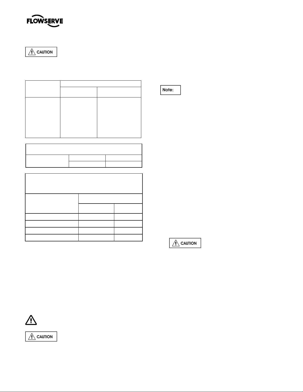
MARK 3 GROUP 4 USER INSTRUCTIONS ENGLISH 71569286 08-12
®
6.6 Fastener torques
Non-metallic gaskets incur creep
relaxation – retighten to the tightening torques
provided.
All torques specified subject to a tolerance of +/- 10%
Bolt size
M 16 (⅝ in.)
M 20 (¾ in.)
M 24 (⅞ in.)
M 27 (1 in.)
M 30 (1⅛ in.)
M 36 (1⅜ in.)
M 42 (1⅝ in.)
M 48 (1⅞ in.)
Pump feet
1 100 (810)
1 840 (1 350)
2 000 (1 475)
2 240 (1 650)
Torque Nm (lbft)
fasteners
170 (125)
340 (250)
590 (435)
770 (570)
All other fasteners
84 (62)
165 (120)
285 (210)
375 (275)
540 (400)
900 (660)
1 410 (1 040)
2 060 (1 500)
IMPELLER NUT
TIGHTENING TORQUE
FRAME 4K
Nm lbf.ft.
400 300
TIGHTENING TORQUE FOR STAINLESS STEEL
STUDS
WITH LUBRICATED THREADS
THREAD SIZE
M10x1.5 (3/8–16UNC) 13 10
M12x1.75 (1/2–13UNC) 27 20
M16X2 (5/8-11UNC) 60 45
M20x2.5 (¾-10UNC) 100 75
TIGHTENING TORQUE
Nm
ft. lb.
6.7 Renewal clearances
As wear takes place between the impeller and casing
the overall efficiency of the pump set will decrease.
To maintain optimum efficiency it is recommended
that the impeller be adjusted to maintain the impeller
axial clearance as detailed in section 6.11 to
clearance as detailed in table 3.5. Typically doubling
the clearance can reduce performance by 5%
depending on pump size and operating condition.
6.8 Disassembly
Refer to section 1.6, Safety, before dismantling
the pump.
Before dismantling the pump for
overhaul, ensure genuine Flowserve replacement
parts are available.
To disassemble the pump consult the sectional
drawings, see section 8, Parts list and drawings.
6.8.1 Rotor unit
The following procedure is recommended for
removing and disassembling the back pull-out
element (rotating assembly).
Note that the replacement gaskets and
similar consumable materials should be available
since they will be required for reassembly.
a) Isolate motor and lock off electrical supply in
accordance with local regulations.
b) Isolate suction and discharge valves.
c) Remove coupling guards and disconnect the
coupling halves.
d) Drain pump casing. Remove any auxiliary piping
if applicable.
e) Disconnect stuffing box, cooling water and
auxiliary piping.
f) Drain the oil from the bearing frame [3130] if
bearing frame is being dismantled.
g) Place the sling around the bearing frame [3130]
and carefully take up the weight without straining
the casing. Refer to Section 3 to determine hoist
and sling requirements.
h) Release the thrust bearing housing [3240] hold
down bolts and jam nuts. While rotating the
pump shaft [6] by hand, tighten the three jacking
screws evenly until the impeller [2200] lightly
clamps the stuffing box head [4110] in place.
This will simplify withdrawal of the rotating
element from the casing.
Excessive clamping force could
damage bearing races.
Rotating the shaft helps to clear away solids
which may be trapped between the impeller and
stuffing box head.
i) Remove the bolts connecting the rear support
foot [3134] to the baseplate.
j) Remove the frame to casing bolts
k) Withdraw the rotating element from the casing.
6.8.2 Stuffing box
6.8.2.1 Shaft seal - mechanical seal
Refer to any special instructions supplied with the
mechanical seal.
a) Remove seal cover screws and pull off seal cover
complete with the stationary seal ring which is
held in place by the O-ring seal.
Page 34 of 48 flowserve.com
Page 35

MARK 3 GROUP 4 USER INSTRUCTIONS ENGLISH 71569286 08-12
®
b) The mechanical seal cover can also be removed
by placing a wedge into the gland chamfer, as
below:
6.8.2.2 Impeller and stuffing box
a) While preventing the shaft from rotating, remove
the impeller nut [2912] that has a right hand
thread.
b) Remove the impeller [2200] and impeller key
[6700]. Normally, a slight tightening of the thrust
gearing jacking screws will free the impeller and
allow it to be removed. Except on the smaller
sizes, there is a facility on the impeller hub to
assist removal in difficult cases.
6.8.3 Shaft sleeve
a) Remove the shaft sleeve gasket [4590.3].
b) Remove the shaft sleeve [2445] if scored or
worn.
6.8.4 Bearing housing
a) Remove the line bearing seal.
b) Remove the pump half coupling and coupling key
[6710].
c) Remove the bearing frame support [3134].
d) Lift the bearing frame assembly into a vertical
position with the thrust bearing housing [3240]
up. Rest the bearing frame flange on heavy
wooden blocks sufficiently high to ensure end of
the shaft does not come into contact with the
floor or table.
e) Remove the thrust bearing hold down bolts and
remove shaft assembly for the bearing frame
[3130].
6.8.5 Line bearing
a) Lay the shaft [2110] horizontal and support with
wooden ‘V’ Blocks.
b) Only if necessary remove the line bearing [3011]
from the shaft. Bearings removed and reused
can easily be damaged and undetected until
pump is put back in operation.
6.8.6 Thrust bearings
a) Lay the shaft [2110] horizontal and support with
wooden ‘V’ Blocks.
b) Remove the thrust bearing clamp ring [2542]
from the thrust bearing housing [3240].
c) Bend up the locking tab on the bearing
lockwasher [6542] and remove the bearing
locknut [3712] and lockwasher [6542].
d) Only if necessary remove the thrust bearings
[3031] from the shaft. Bearings removed and
reused can easily be damaged and undetected
until pump is put back in operation
6.9 Examination of parts
Used parts must be inspected before
assembly to ensure the pump will subsequently run
properly.
In particular, fault diagnosis is essential to enhance
pump and plant reliability.
6.9.1 Casing, seal housing and impeller
a) Inspect for excessive wear, pitting, corrosion,
erosion or damage and any sealing surface
irregularities.
b) Replace as necessary.
c) Inspect the impeller [2200] for excessive wear or
damage. Inspect the casing [1112] and stuffing
box head [4110] for damage or excessive
thinning of wall sections due to wear or
corrosion. Clean the internal surfaces to
maintain pump efficiency.
d) Clean the internal bore of the stuffing box.
6.9.2 Shaft and sleeve [if fitted)
a) Replace sleeve if grooved, pitted or worn.
b) Clean the shaft and inspect for evidence of
corrosion, evidence of cracking, fatigue or
mechanical damage. Remove all burrs or nicks
paying particular attention to the areas under the
lip seals. Check that the shaft is straight within
0.002 inch (0.050 mm).
6.9.3 Gaskets and O-rings
After dismantling, discard and replace.
6.9.4 Bearings
a) It is recommended that bearings are not re-used
after any removal from the shaft.
b) The plain liquid lubricated bearings may be re-
used if both the bearing bush and bearing sleeve
show no sign of wear, grooving or corrosion
attack. (It is recommended that both the bush
and sleeve are replaced at the same time.)
6.9.5 Bearing isolators, labyrinths or lip seals
(if fitted)
a) The lubricant, bearings and bearing housing
seals are to be inspected for contamination and
damage. If oil bath lubrication is utilised, these
provide useful information on operating
conditions within the bearing housing.
b) If bearing damage is not due to normal wear and
the lubricant contains adverse contaminants, the
cause should be corrected before the pump is
returned to service.
c) Labyrinth seals and bearing isolators should be
inspected for damage but are normally non-
wearing parts and can be re-used.
Page 35 of 48 flowserve.com
Page 36

MARK 3 GROUP 4 USER INSTRUCTIONS ENGLISH 71569286 08-12
®
d) Bearing seals are not totally leak free devices.
Oil from these may cause staining adjacent to
the bearings.
6.9.6 Installed pump
Complete pump installed.
Shaft movement caused by pipe strain
Pipe strain is any force put on the pump casing by
the piping. Pipe strain should be measured as shown
below. Install the indicators as shown before
attaching the piping to the pump. The suction and
discharge flanges should now be bolted to the piping
separately while continuously observing the
indicators. Indicator movement should not exceed
0.05 mm (0.002 in.).
Pipe strain movement
Alignment
Misalignment of the pump and motor shafts can
cause the following problems:
• Failure of the mechanical seal
• Failure of the motor and/or pump bearings
• Failure of the coupling
• Excessive vibration/noise
The schematics below show the technique for a
typical rim and face alignment using a dial indicator.
It is important that this alignment be done after the
flanges are loaded, and at typical operating
temperatures.
See section 4.8 for recommended final shaft
alignment limits.
Vibration analysis
Vibration analysis is a type of condition monitoring
where a pump’s vibration “signature” is monitored on
a regular, periodic basis. The primary goal of
vibration analysis is extension on MTBPM. By using
this tool Flowserve can often determine not only the
existence of a problem before it becomes serious,
but also the root cause and possible solution.
Modern vibration analysis equipment not only detects
if a vibration problem exists, but can also suggest the
cause of the problem. On a centrifugal pump, these
causes can include the following: unbalance,
misalignment, defective bearings, resonance,
hydraulic forces, cavitation and recirculation. Once
identified, the problem can be corrected, leading to
increased MTBPM for the pump.
Flowserve does not make vibration analysis
equipment, however Flowserve strongly urges
customers to work with an equipment supplier or
consultant to establish an on-going vibration analysis
program. See 5.7.5 regarding acceptance criteria.
6.10 Assembly
To assemble the pump consult the sectional
drawings, see section 8, Parts list and drawings.
Ensure threads, gasket and O-ring mating faces are
clean. Apply thread sealant to non-face sealing pipe
thread fittings.
6.10.1 Bearing housing
a) Lubricate the internal bores of the bearing frame
[3130] with the same oil or grease used to
lubricate the bearings.
b) Install the thrust bearing housing [3240] in the
bearing frame [3130] to ensure a good sliding fit.
Remove the thrust bearing housing from the
frame.
c) Install the oil sight gauge [3856] and the drain lug
in the bearing frame [3130] using Teflon pipe
thread sealant. Install the vent plug [6521].
Many companies today are using laser alignment
which is a more sophisticated and accurate
technique. With this method a laser and sensor
measure misalignment. This is fed to a computer with
a graphic display that shows the required adjustment
for each of the motor feet.
6.10.2 Line bearing
a) Pack the line bearing with grease if the bearings
are being grease lubricated.
b) Lightly lubricate the shaft [2110] at the line
bearing position. Install the line bearing [3011]
on the shaft. Use an induction heated or hot oil
bath to first heat the bearing [250° F
Page 36 of 48 flowserve.com
Page 37

MARK 3 GROUP 4 USER INSTRUCTIONS ENGLISH 71569286 08-12
®
recommended], press the bearing on shaft with
the aid of a sleeve designed to push the inner
race only. Note that the bearing must remain
square to the shaft during assembly and that the
inner race must seat on the shaft shoulder.
Protect the bearing by wrapping with a clean, lint
free cloth.
6.10.3 Thrust bearing
a) Pack thrust bearing with grease if the bearings
are being grease lubricated.
b) Place the thrust bearing clamp ring [2542]
loosely over the shaft on the largest diameter.
c) Install the angular contact bearings [3031] on the
shaft [2110] using the same procedure as
described in step 6.10.2. The bearings are
mounted back to back as shown.
Bearing arrangement
d) Slide the bearing lockwashers [6541] on the shaft
and fit the bearing locknut [3712]. Tighten the
locknut snugly and allow to cool. Check the
tightness and bend one tab on the lockwasher
into a slot in the locknut. Protect the bearings
from contamination.
e) Carefully install the IN seal [4300.2] in the thrust
bearing housing [3240] by pressing it squarely
into the bore. The primary sealing lip [spring
loaded] on seal should be installed facing the
bearing. A small amount of sealant may be
applied on the O.D. of the seal prior to its'
installation.
f) Lubricate the O-rings [4610.3] with the bearing
lubricant and assemble it into the groove of the
outer circumference of the thrust bearing housing
[3240].
g) Lubricate the inside bore of the thrust bearing
housing [3240] and assemble it over the thrust
bearings. Care must be taken to prevent
damage of the seal on the shaft.
h) Using capscrews and lockwashers, attach the
thrust bearing clamp ring [2542] to the thrust
bearing housing [3240]. Lock the threads using
Loctite 242 or equivalent.
The thrust bearing clamp ring [2542] is
provided with one extra hole midway between two
adjacent bolt holes to permit free oil flow. On oil
lubricated units, this hole must align with the cast oil
return at the bottom of the thrust bearing housing
bore. For grease lubricated units, this hole should be
oriented away from the cast oil return slot at the
bottom the thrust bearing housing bore.
Tighten the capscrews evenly ensuring that the
clamp ring is not distorted and gap to the bearing
housing is even all around. Tighten in accordance
with section 6.6.
6.10.4 Frame assembly
a) Place the bearing frame in a vertical position with
the large flange resting on wooden support
blocks sufficiently high to allow the shaft from
contacting the floor when it is installed.
b) Lift the shaft assembly into a vertical position and
lower it into the bearing frame [3130].
c) Screw the thrust bearing housing into bearing
frame housing at least 7 revolutions to prevent
the assembly from coming apart when lifting.
d) Place the bearing frame assembly into a
horizontal position.
e) Install the setscrews [6577].
f) Carefully install the INPRO seal [4300.2] in the
line bearing frame [3130] by pressing it squarely
into the bore. A small amount of sealant may be
applied on the O-ring of the seal prior to its'
installation.
g) Install the coupling key [6700] and tape to the
shaft.
Mount a dial indicator to the bearing frame [3130]
h)
and indicate shaft under bearing frame flange
(approx. mid way between impeller mounting face
and end of sleeve area. Rotate shaft and check that
run-out does not exceed 0.050 mm (0.002 in.).
6.10.5 Stuffing box
6.10.5.1 All
a) Install the gland studs [6572] using Loctite grade
A or equivalent. The gland studs [6572] on water
cooled stuffing boxes must be sealed with pipe
sealant. If only two gland studs are used, the
remaining two tapped holes must be plugged
with set screws or short capscrews. To ensure
proper sealing, the chamber can be tested to a
design pressure of 75psi.
b) Press the stuffing box neck bush [4132] into the
stuffing box [4110], ensuring that it seats squarely
on the shoulder.
c) Lubricate the shaft [2110] at the impeller position,
Page 37 of 48 flowserve.com
Page 38

MARK 3 GROUP 4 USER INSTRUCTIONS ENGLISH 71569286 08-12
®
check the fit of the impeller key [6710] in the
shaft keyway and install the impeller [2200] onto
the shaft to ensure that there is a good sliding fit.
Remove the impeller [2200] and the impeller key
[6710].
d) Install the O-ring [4610.2] into the impeller nut
[2912] using grease or anti-seize compound to
hold it in place during assembly.
e) Install the shaft sleeve [2445] onto the shaft
[2110] and orientate the sleeve such that the
keyways are aligned. Install the impeller key
[6710] in the shaft.
6.10.5.2 Standard Packing
a) Assemble the stuffing box head [4110] over the
shaft sleeve [2445] and orientate the lantern ring
connections to auxiliary piping (Refer to Figure 6).
These connections are normally placed on the
vertical centerline for proper venting and draining as
well as providing optimum gland stud access.
b) Push the stuffing box head [4110] back against the
bearing frame flange face. Back off the thrust
bearing housing to line up with the stuffing box with
shaft sleeve. The shaft sleeve should be lined up
with the stuffing box or fairly proud off the stuffing
box by 0.060” [1.50mm].
c) Install the shaft gasket [4590.3] onto the shaft,
ensuring that the outside diameter is no larger than
the sleeve.
as to balance the weight, lift the frame/impeller
assembly keeping the shaft horizontal.
b) Install the frame/impeller assembly into the
casing [1112] by guiding the stuffing box head
and bearing frame spigots squarely into the
casing recess. Ensure that the gasket [4590.3]
stays in position. If the fit becomes snug, use 4
equally spaced bolts to draw the assembly into
the casing.
c) Install the casing frame bolts with washers and
tighten in accordance with section 6.6.
d) Using the thrust bearing housing adjustment
feature [Figure 1], move the impeller forward
away from the stuffing box head [4110].
e) Attach the bearing frame support [3134] to the
bearing frame [3130] using the capscrews and
washers. Ensure that thread engagement is at
least 1 diameter. Use Loctite 242 thread sealant.
f) Set the impeller front clearance in accordance
with instruction earlier in this section of the
manual.
6.10.9 Shaft seal
6.10.9.1 Gland packing
6.10.6 Impeller Installation
a) Install impeller [2200].
b) Apply a small quantity of Loctite 242 or
equivalent to the exposed thread on the end of
the shaft, and thread the impeller nut [2912]
complete with O-ring [4610.2] onto the shaft.
For units with mechanical seals, do not
apply thread locking compound until seal axial
setting has been established.
c) Tighten the impeller nut [2912] in accordance
with the specific Impeller torque specified, see
section 6.6. This is an essential step to properly
seat the sleeve [2445] and compress the gasket
[4590.3] to provide a seal and to prevent
loosening of the impeller on the shaft.
d) Release the thrust bearing housing set screws
[6577] and index the bearing housing [3240] to
move the impeller in or out.
6.10.7 All pumps
a) Smear anti-seize compound on the casing [1112]
and stuffing box head [4110] rabbit fit (spigot)
diameters to ease assembly and future
disassembly.
6.10.8 Rotor unit
a) With a sling around the bearing frame placed so
Standard Packed Box Arrangement
Insert one packing ring at a time into the stuffing
a)
box. Push the packing as far as possible into the
packing bore.
b) Install additional rings as required, staggering the
joints.
c) Once the first two or three rings of packing have
been inserted, the two piece lantern ring [4134]
must be installed. Push the lantern ring and
previously installed packing. The ports in the lantern
ring do not need to be aligned with the inlet/outlet
ports.
d) Ensure that the shaft can be turned by hand.
e) Install the remaining rings of packing, alternating
the joints.
It may not be possible to insert the last ring in
Page 38 of 48 flowserve.com
Page 39
MARK 3 GROUP 4 USER INSTRUCTIONS ENGLISH 71569286 08-12
®
the box and still insert the gland. In this case, omit
the last ring of packing and install the gland. The
last ring of packing should be installed after the
pump has been in service and sufficient space is
available.
f) Install the gland halves [4120], tighten the gland
nuts [6581] only finger tight.
New packing has to be run-in and it is
good practice to start the pump with the stuffing box
gland quite loose. Packing that is too tight in the
box will cause undue friction, creating heat which
will glaze the packing and possible score the shaft
sleeves. To be effective, the packing must remain
soft and pliable. If stuffing box friction is so great
that the pump shaft cannot be turned by hand, the
box is not properly packed.
6.10.9.2 Mechanical Seal
Refer to any special instructions supplied with the
mechanical seal.
a) Before the mechanical seal can be installed, the
pump must be assembled with the correct
impeller running clearances (ie: all assembly
steps above). A scribe mark is then placed on
the circumference of the sleeve to mark the end
of the box. This mark is used to locate the seal
position referenced by the mechanical seal
drawing provided.
b) After scribing the sleeve, remove the rotating
element from the casing. Do not adjust the
bearing housing.
c) Remove the impeller nut [2912], impeller [2200],
impeller key [6710] and stuffing box head [4110].
Assemble the mechanical seal components,
including gland plates, gaskets and rotating parts
over the sleeve. Locate the seal relative to the
scribed markings on the shaft sleeve [2445] as
indicated by the seal manufacturers’ instruction.
d) Remove lubricating compound from the impeller
nut and shaft threads. Re-assemble components
in accordance with original assembly procedure
with the exception that Loctite 242 is applied to
the impeller nut [2912] threads. Torque the
impeller nut to the specified value, see section
6.6.
e) Assemble the mechanical seal gland plate and
gasket and fasten using gland studs [6572].
Secure with nuts [6581] and tighten each by
hand. Further tighten the nuts in accordance with
section 6.6. Rotate the shaft to ensure that it
turns freely without rubbing or binding.
f) Re-assemble the rotating element into the
casing. Do not adjust the thrust bearing housing.
6.10.10 Final assembly
a) Lift the assembled pump onto the baseplate,
position the casing feet over the tapped holes in
the baseplate and clamp them.
b) Loosen the bolts that attach the rear support foot
[3134] to the bearing frame [3130]. The rear
support foot is designed with shim allowance
measured vertically. Level the unit and align with
the piping. Tighten the bolts attaching the casing
feet to the baseplate in accordance with the
specific torque specified, see section 6.6. Do not
distort casing or frame.
c) Install the pump coupling or sheave as required.
d) Refer to Section 4, Installation and Section 5,
Preparation for Operation.
e) It is recommended that the pump not be packed
until required. Refer to stuffing box packing
procedure in this section. Protect the stuffing box
bore and seal area with clean dry rags.
Gland packing must not be used when pumping
hazardous liquids.
6.11 Impeller axial clearance adjustment
This procedure should not be used on units
with mechanical seals if the design is such that a
liquid seal cannot be maintained when the rotor is
moved axially against the wear plate.
Unless seal is a cartridge design it may not be
possible to adjust the shaft unless the pump is
dismantled.
Refer to any special instructions supplied with
the mechanical seal
NEVER ATTEMPT TO CHANGE THE
CLEARANCE WHEN THE PUMP IS RUNNING.
If the coupling has limited axial adjustment capability,
the pump and driver must be uncoupled prior to
adjusting the clearance in order to permit free
movement.
A new impeller gasket [4590.3] must be installed
whenever the impeller has been removed from the
shaft.
6.11.1 Installation and clearance setting for
impellers on Mark 3 Group 4 pump
The impeller could have sharp edges, which
could cause an injury. It’s very important to wear
heavy gloves.
a) Install impeller [2200], see section 6.10.6.
Page 39 of 48 flowserve.com
Page 40

MARK 3 GROUP 4 USER INSTRUCTIONS ENGLISH 71569286 08-12
®
b) Set the impeller clearance by loosening the set
screws [6577] and rotating the thrust bearing
housing [3240] to obtain the clearance. Turn the
thrust bearing housing counter-clockwise until
the impeller comes into light rubbing contact with
the casing [1112]. Rotating the shaft at the same
time will accurately determine this zero setting.
Now, rotate the thrust bearing housing clockwise
to get the proper clearance. Rotating the thrust
bearing housing the width of one of the indicator
patterns cast into the thrust bearing housing
moves the impeller axially 0.1 mm (0.004 in).
(Figure 2).
It is recommended that two
people install an impeller. The weight of an impeller
greatly increases the chance of thread damage and
subsequent lock-up concerns.
c) Determine how far to rotate the thrust bearing
housing by dividing the desired impeller
clearance by 0.10 (one indicator pattern).
Tightening the set screws [6577] will cause the
impeller to move 0.005 mm (0.002 in) closer to
the casing because of the internal looseness in
the thrust bearing housing threads. This must be
considered when setting the impeller clearance.
Rotate the thrust bearing housing clockwise the
required amount to get the desired clearance to
the casing. Lastly, tighten the set screws [6577]
to lock the thrust bearing housing in place.
Page 40 of 48 flowserve.com
Page 41

MARK 3 GROUP 4 USER INSTRUCTIONS ENGLISH 71569286 08-12
®
7 FAULTS; CAUSES AND REMEDIES
FAULT SYMPTOM
Pum p overheats and s eizes
Bearings have short life
⇓⇓⇓⇓
Pum p vibrates or is nois y
⇓⇓⇓⇓
Mechanical se al has short life
⇓⇓⇓⇓
Mechanical se al leaks exces sively
⇓⇓⇓⇓
Pum p requires excessive power
⇓⇓⇓⇓
Pum p loses prim e after starting
⇓⇓⇓⇓
Insufficient pressur e develop ed
⇓⇓⇓⇓
Insufficient capacity deliver ed
⇓⇓⇓⇓
Pum p does not deliver liquid
⇓⇓⇓⇓
⇓⇓⇓⇓
POSSIBLE CAUSES POSSIBLE REMEDIES
Pump not primed.
Pump or suction pipe not completely filled with
liquid.
Suction lift too high or level too low.
Insufficient margin between suction pressure and
vapour pressure.
Excessive amount of air or gas in liquid. Check and purge pipes and system.
Air or vapour pocket in suction line. Check suction line design for vapour pockets.
Air leaks into suction line. Check suction pipe is airtight.
Air leaks into pump through mechanical seal,
sleeve joints, casing joint or pipe plugs.
Foot valve too small. Investigate replacing the foot valve.
Foot valve partially clogged. Clean foot valve.
Inlet of suction pipe insufficiently submerged. Check out system design.
Speed too low. CONSULT FLOWSERVE.
Speed too high. CONSULT FLOWSERVE.
Total head of system higher than differential head
of pump.
Total head of system lower than pump design
head.
Specific gravity of liquid different from design.
Viscosity of liquid differs from that for which
designed.
Operation at very low capacity.
Operation at high capacity.
Misalignment due to pipe strain.
Improperly designed foundation.
Shaft bent.
A. System troubles
Check complete filling. Vent and/or prime.
Check NPSHa>NPSHr, proper submergence,
losses at strainers/fittings.
Check and replace faulty parts.
CONSULT FLOWSERVE.
Check system losses.
Remedy or CONSULT FLOWSERVE.
Check and CONSULT FLOWSERVE.
Measure value and check minimum permitted.
Remedy or CONSULT FLOWSERVE.
Measure value and check maximum permitted.
Remedy or CONSULT FLOWSERVE.
B. Mechanical troubles
Check the flange connections and eliminate strains
using elastic couplings or a method permitted.
Check setting of baseplate: tighten, adjust, grout
base as required.
Check shaft run-outs are within acceptable values.
Page 41 of 48 flowserve.com
Page 42

®
FAULT SYMPTOM
Pum p overheats and s eizes
Bearings have short life
⇓⇓⇓⇓
Pum p vibrates or is nois y
⇓⇓⇓⇓
Mechanical se al has short life
⇓⇓⇓⇓
Mechanical se al leaks exces sively
⇓⇓⇓⇓
Pum p requires excessive power
⇓⇓⇓⇓
Pum p loses prim e after starting
⇓⇓⇓⇓
Insufficient pressur e develop ed
⇓⇓⇓⇓
Insufficient capacity deliver ed
⇓⇓⇓⇓
Pum p does not deliver liquid
⇓⇓⇓⇓
⇓⇓⇓⇓
POSSIBLE CAUSES POSSIBLE REMEDIES
Rotating part rubbing on stationary part internally. Check and CONSULT FLOWSERVE, if necessary.
Bearings worn Replace bearings.
Wearing ring surfaces worn. Replace worn wear ring/surfaces.
Impeller damaged or eroded.
Leakage under sleeve due to joint failure. Replace joint and check for damage.
Shaft sleeve worn or scored or running off centre. Check and renew defective parts.
Mechanical seal improperly installed.
Incorrect type of mechanical seal for operating
conditions.
Shaft running off centre because of worn bearings
or misalignment.
Impeller out of balance resulting in vibration.
Abrasive solids in liquid pumped.
Internal misalignment of parts preventing seal ring
and seat from mating properly.
Mechanical seal was run dry.
Internal misalignment due to improper repairs
causing impeller to rub.
Excessive thrust caused by a mechanical failure
inside the pump.
Lack of lubrication for bearings.
Improper installation of bearings (damage during
assembly, incorrect assembly, wrong type of
bearing etc).
Damaged bearings due to contamination.
Wrong direction of rotation. Reverse 2 phases at motor terminal box.
Motor running on 2 phases only. Check supply and fuses.
Motor running too slow. Check motor terminal box connections and voltage.
MARK 3 GROUP 4 USER INSTRUCTIONS ENGLISH 71569286 08-12
CONSULT FLOWSERVE.
Replace or CONSULT FLOWSERVE for improved
material selection.
Check alignment of faces or damaged parts and
assembly method used.
CONSULT FLOWSERVE.
Check misalignment and correct if necessary. If
alignment satisfactory check bearings for excessive
wear.
Check and CONSULT FLOWSERVE.
Check mechanical seal condition and source of dry
running and repair.
Check method of assembly, possible damage or
state of cleanliness during assembly.
Remedy or CONSULT FLOWSERVE, if necessary.
Check wear condition of impeller, its clearances and
liquid passages.
Check hours run since last change of lubricant, the
schedule and its basis.
Check method of assembly, possible damage or
state of cleanliness during assembly and type of
bearing used. Remedy or CONSULT
FLOWSERVE, if necessary.
Check contamination source and replace damaged
bearings.
C. MOTOR ELECTRICAL PROBLEMS
Page 42 of 48 flowserve.com
Page 43
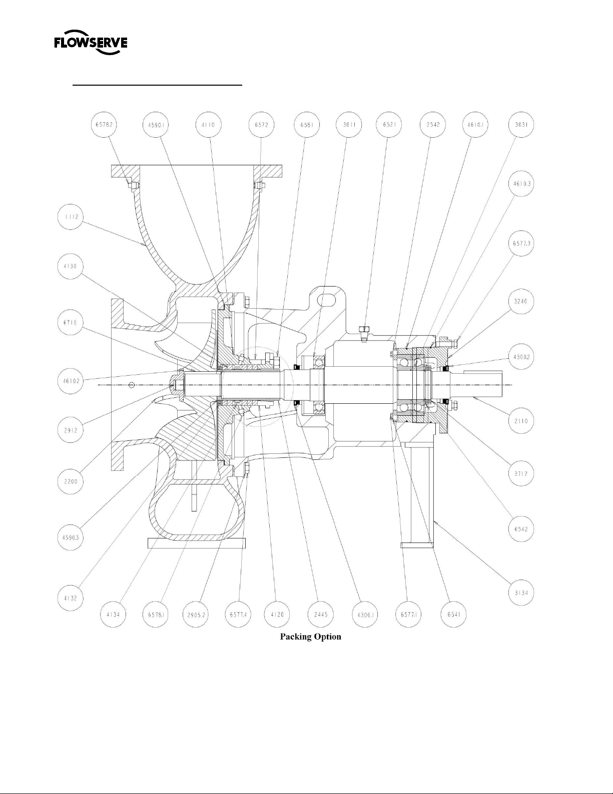
MARK 3 GROUP 4 USER INSTRUCTIONS ENGLISH 71569286 08-12
®
8 PARTS LIST AND DRAWINGS
8.1 Mark 3 Group 4 chemical pump sectional and parts list
Page 43 of 48 flowserve.com
Page 44

MARK 3 GROUP 4 USER INSTRUCTIONS ENGLISH 71569286 08-12
®
Euro.
Description
Euro.
Description
Euro.
Description
1112 Casing 3856 Plug, Level Sight
1230 Handhole Cover 4110 Stuffing Box
2110 Shaft
2200 Impeller
2445 Shaft Sleeve
2542 Clamp Ring
2905.1 Washer
2905.2 Washer
2912 Impeller Nut
3011 Radial Ball Bearing
3031 Thrust Bearing
3130 Bearing Frame
3134 Support Foot
3240 Thrust Brg.Hsg.
3712 Lock Nut
4120
4130
4132
4134
4200
4300.1
4300.2
4590.1
4590.2
4590.3
4610.1
4610.2
4610.3
Gland Halves 6541 Lockwasher
Packing 6542 Lockwasher
Throat Bushing
Seal Cage Halves 6577.1 Cap Screw Hex Head
Mechanical Seal 6577.2 Cap Screw Hex Head
Inpro Seal 6577.3 Cap Screw Hex Head
Inpro Seal 6577.4 Cap Screw Hex Head
Gasket 6578.1 Plug, Pipe
Gasket, Hand-hole 6578.2 Square Head Pipe Plug
Gasket, Sleeve 6578.3 Square Head Pipe Plug
O-Ring 6581 Hex Nut
O-Ring
O-Ring
6515
6521
6572
6700
6710
Plug, Drain
Breather Plug
Stud
Key
Key, Sleeve
Page 44 of 48 flowserve.com
Page 45

MARK 3 GROUP 4 USER INSTRUCTIONS ENGLISH 71569286 08-12
®
8.2 Mark 3 Group 4 chemical pump- liquid end exploded view
Page 45 of 48 flowserve.com
Page 46

MARK 3 GROUP 4 USER INSTRUCTIONS ENGLISH 71569286 08-12
®
8.3 Mark 3 Group 4 chemical pump frame exploded view
Page 46 of 48 flowserve.com
Page 47

MARK 3 GROUP 4 USER INSTRUCTIONS ENGLISH 71569286 08-12
®
8.4 General arrangement drawing
The typical general arrangement drawing and any
specific drawings required by the contract will be sent
to the Purchaser separately unless the contract
specifically calls for these to be included into the
User Instructions. If required, copies of other
drawings sent separately to the Purchaser should be
obtained from the Purchaser and retained with these
User Instructions.
9 CERTIFICATION
Certificates, determined from the contract
requirements will be provided with this manual.
Examples are certificates for CE marking and ATEX
marking. If required, copies of other certificates sent
separately to the Purchaser should be obtained from
Purchaser for retention with the User Instructions.
See section 1.9, Noise level, for details of typical
noise certification.
10 OTHER RELEVANT
DOCUMENTATION AND MANUALS
10.3 Additional sources of information
Reference 1:
NPSH for Rotordynamic Pumps: a reference guide,
Europump Guide No. 1, Europump & World Pumps,
Elsevier Science, United Kingdom, 1999.
Reference 2:
Pumping Manual, 9
Elsevier Advanced Technology, United Kingdom,
1995.
Reference 3:
Pump Handbook, 2nd edition, Igor J. Karassik et al,
McGraw-Hill Inc., New York, 1993.
Reference 4:
ANSI/HI 1.1-1.5
Centrifugal Pumps - Nomenclature, Definitions,
Application and Operation.
Reference 5:
ANSI B31.3 - Process Piping.
th
edition, T.C. Dickenson,
10.1 Supplementary User Instruction
manuals
Supplementary instruction determined from the
contract requirements for inclusion into User
Instructions such as for a driver, instrumentation,
controller, sub-driver, seals, sealant system,
mounting component etc. are included under this
section. If further copies of these are required they
should be obtained from the purchaser for retention
with these User Instructions.
Where any pre-printed set of User Instructions are
used, and satisfactory quality can be maintained only
by avoiding copying these, they are included at the
end of these User Instructions such as within a
standard clear polymer software protection envelope.
10.2 Change notes
If any changes, agreed with Flowserve Pump
Division, are made to the product after its supply, a
record of the details should be maintained with these
User Instructions.
Page 47 of 48 flowserve.com
Page 48

MARK 3 GROUP 4 USER INSTRUCTIONS ENGLISH 71569286 08-12
®
Local Flowserve factory representatives:
Your Flowserve factory contacts:
Flowserve Pump
5310 Taneytown Pike
PO Box 40
Taneytown, Md, USA
21787
Telephone +1 (410) 756 2602
Fax +1 (410) 756 2615
Flowserve Pump
15 Worthington Dr.
PO Box 40
Brantford, Ontario, Canada
N3T 5M5
Telephone +1 (519) 753 7381
Fax +1 (519) 753 0845
In Europe:
Flowserve Pumps Limited
PO Box 17, Newark
Notts NG24 3EN
United Kingdom
Telephone (24 hours): +44 (0)1636 494 600
Sales & Admin Fax: +44 (0)1636 705 991
Repair & Service Fax : +44 (0)1636 494 833
E.mail inewark@flowserve.com
FLOWSERVE REGIONAL
SALES OFFICES:
USA and Canada
Flowserve Corporation
5215 North O’Connor Blvd.,
Suite 2300
Irving, Texas 75039-5421, USA
Telephone +1 972 443 6500
Fax +1 972 443 6800
Europe, Middle East, Africa
Flowserve FSG – Italy
Worthing S.r.l.
Via Rossini 90/92
20033 Desio (Milan), Italy
Telephone +39 0362 6121
Fax +39 0362 628 882
Latin America and Caribbean
Flowserve Corporation
6840 Wynnwood Lane
Houston, Texas 77008, USA
Telephone +1 713 803 4434
Fax +1 713 803 4497
Asia Pacific
Flowserve Pte. Ltd
10 Tuas Loop
Singapore 637345
Telephone +65 6771 0600
Fax +65 6862 2329
Page 48 of 48 flowserve.com
 Loading...