

Page 1
Installation, Operation and Maintenance
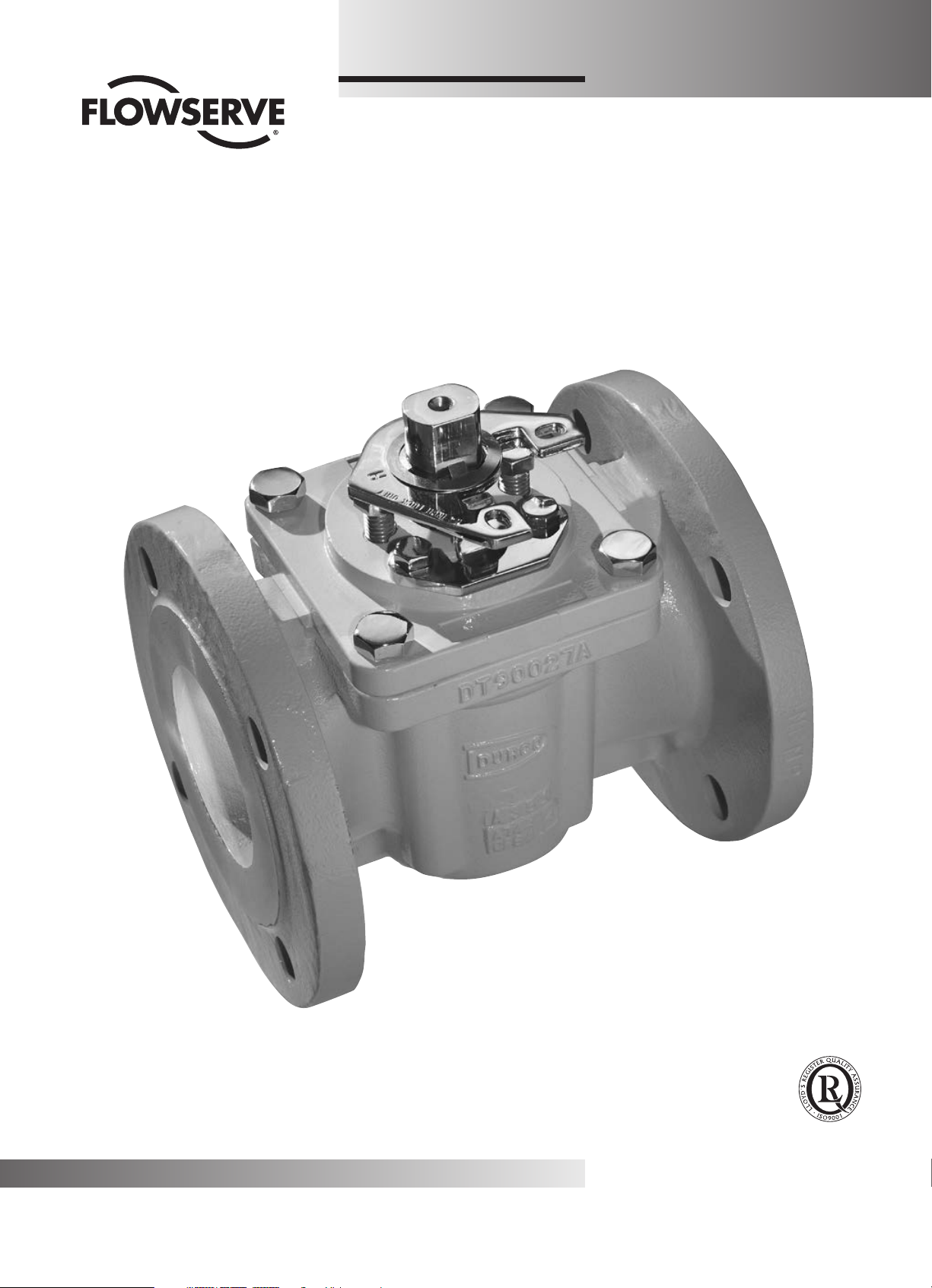
Marathon-Mach 1
HIGH PERFORMANCE
PLUG VALVE
™
Breaking The Barriers
Quality
System
Certificate
Bulletin
DVENIM0333
Page 2
Flow Control Division
Section 1.0
PRESSURE CONTAINING FASTENERS (continued)
TABLE OF CONTENTS
SECTION TITLE PAGE
I INSTALLATION ................................................................................2
II OPERATING/MAINTENANCE INSTRUCTIONS FOR MARATHON-MACH 1 .................................... 3
III VALVE DISASSEMBLY - MARATHON-MACH 1
RECOMMENDED PRECAUTIONARY MEASURES .......................................................4
DISASSEMBLY STEPS ...........................................................................4
IV PRESSURE CONTAINING FASTENERS ..............................................................5
V A. VALVE ASSEMBLY 1"- 6" MARATHON-MACH 1 WITH PORT SEALS ......................................6
B. VALVE ASSEMBLY 1"- 6" MARATHON-MACH 1 WITH SLEEVE .......................................... 9
VI ASSEMBLY SPECIFICATIONS - FIRESEAL VALVES 1"- 6" MARATHON-MACH 1 .............................. 10
SECTION I
INSTALLATION INSTRUCTIONS - FLANGED MARATHON-MACH 1, CLASS 150, 300 AND 600
FLANGED:
Installation of Flowserve flanged valves is best accomplished
by locating valves in pipeline flanges, assuring all corrosion and
foreign materials are removed from pipe flanges and then center
gaskets with the valve flanges. Fasteners or taper pins should
be used to align holes and locate gaskets. Fasteners should be
tightened to the corresponding valve and fastener size.
2
TABLE I-1
Temperature Limitations
Type
PFA
P-Seat (port seal, insert) 525°F (274°C)
UMPE 200°F (93°C)
Tefzel 300°F (149°C)
Material
Description
R-Seat (full, no insert) 400°F (274°C)
S-Seat (full, insert) 525°F (204°C)
Maximum Service
Temperature
Page 3
SECTION II
OPERATING/MAINTENANCE INSTRUCTIONS FOR MARATHON-MACH 1
Flow Control Division
Section 1.0
Maintenance requirements for Marathon-Mach 1 valves may
vary due to operating conditions of the process. Factors such
as operating temperature, pressure, solids content, and
frequency of cycling
maintenance requirements.
Seal wear is compensated by adjusting appropriate parts. For
Mach 1 valves, there are three possible leak paths:
1. Top Cap (bonnet)
2. Stem
3. Line (through)
Corresponding adjustments for each leak path are as follows.
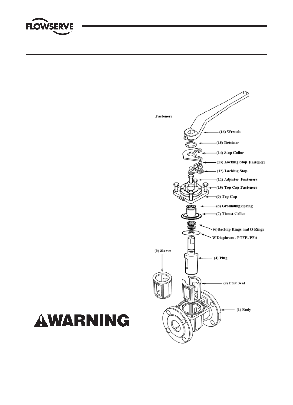
NOTE: Refer to Figure II-1 for parts identification.
1. Top Cap (bonnet)
Leakage due to thermal or pressure cycling is eliminated by
tightening the top cap fasteners (Part 10) in a “criss-cross”
pattern to the torque values given in the tables. This adjustment is most effective when the valve is not pressurized.
It is important that the top cap fasteners not be tightened
excessively and that torque values applied be within
industry standard for fasteners.
2. Stem
Leakage due to wear of the diaphragm, and/or wear to
the sleeve (primary seal) is eliminated by tightening the
adjuster fasteners (Part 11) in 1/4 turn increments. The
adjuster fasteners must be tightened evenly for maximum
adjustment. The valve should be operated between adjustments to assure that the plug properly seats itself into the
sleeve. If leakage persists after repeated adjustments, the
sleeve and diaphragm will require replacement as covered
in Section V and Section VI.
can influence valve performance and
FIGURE II-1
Typical Assembly of Marathon-Mach 1 Valve
3. Line (through)
Through leakage due to wear of the primary seal can be
eliminated by tightening the adjuster fasteners (Part 11)
in 1/4 turn increments. The fasteners must be tightened
evenly for maximum adjustment. The valve should be operated during adjustments to prevent excessive operating
torque. Should leakage persist after repeated adjustments,
the port seals or sleeve will require replacement as covered
in Section V and Section VI.
To avoid personal injury and prevent damage to equipment, do
not operate or repair this valve without observing the following
procedures outlined in this manual.
3
Page 4
SECTION III
VALVE DISASSEMBLY - MARATHON-MACH 1
Flow Control Division
Section 1.0
RECOMMENDED PRECAUTIONARY MEASURES
1. Valves must be relieved of process fluid and pressure
prior to disassembly.
2. Personnel performing disassembly must be suitably
protected and alert for emission of hazardous
process fluid.
DISASSEMBLY STEPS
NOTE: Refer to Figure II-1 for parts identification. If an actuator or gearbox operates the valve, alignment marks should be
noted to assure correct orientation when reassembled. This
may best be accomplished by making matching marks on the
plug stem and operator housing with no burrs made on the
plug stem.
1. Remove the wrench (Part 16), if so equipped. Remove the
stop collar retainer (Part 15), stop collar (Part 14) and
locking stop (Part 12) after marking their orientation.
2. Gradually loosen adjuster fasteners (Part 11) - DO NOT
REMOVE.
3. WARNING: Do not loosen or remove top cap fasteners
(Part 10) when removing an operator. Remove the
operator by unfastening it from the bracket.
10. For Marathon valves, be sure to remove the o-rings and
backup rings first and then the PFA diaphram.
11. Inspect the valve port seals or sleeve for wear or damage,
especially scratches near the top, bottom, and port areas.
If wear or damage is excessive, the port seals/sleeve
should be replaced.
12. Remove port seals or sleeve as follows:
NOTE: Care must be taken not to damage the machined
internal body bore.
a. Lift port seals out of body bowl.
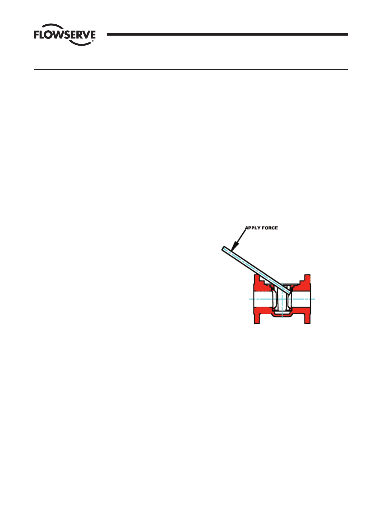
b. To remove the sleeve, use a wooden dowel and pry the
sleeve upward by engaging the dowel in the sleeve at
the top of the port. A sharp blow may be necessary to
dislodge the sleeve. Both sides of the sleeve may need
to be pried upward for removal. (See Figure III-1)
FIGURE III-1
4. Turn plug (Part 4) in order to raise the plug to vent any
material trapped in the valve (see note below).
NOTE: If there is no upward movement of the plug,
it will be necessary to devise a method of lifting the plug
upward. This may require removal of the valve operator
(Step 3). This operation should be undertaken noting the
above precautionary measures. Methods of plug removal
must include protective measures on plug stem and
plug end.
5. Once the plug has lifted, the adjuster fasteners (Part 11)
can be completely removed.
6. Gradually loosen but DO NOT REMOVE all of the top cap
fasteners (Part 10). Turn the plug until it is loose from
the port seal (Part 2) or sleeve (Part 3) and all pressure
has been vented. (Again, it may be necessary to use a
mechanical means to move the plug upwards.)
7. Remove the top cap fasteners and top cap (Part 9) from
the plug stem. Retain the tags for attachment during
re-assembly.
8. Remove the plug (Part 4) from the body (Part 1).
9. Remove the grounding spring (Part 8) and thrust gland
(Part 7).
13. Thoroughly clean all valve parts with an acceptable
cleaner.
14. Inspect parts for damage. Look for marred, scratched,
or rough sealing surfaces on the valve plug or machined
body bore.
NOTE: Reinstallation of damaged or unclean parts will
ruin any replacement seals installed into the valve.
4
Page 5

SECTION IV
PRESSURE CONTAINING FASTENERS
Flow Control Division
Section 1.0
MATERIAL SELECTION
Selecting the proper fastener material is the ultimate
responsibility of the customer because the supplier does
not typically know in what service the valves will be used or
what elements may be present in the environment. Flowserve
normally supplies B7 and B7M (carbon steel) for ductile cast
iron and carbon steel valves. For stainless steel and high
alloy valves, B8, Class 2B (stainless steel, Identified as B9)
fasteners are supplied as standard. All fasteners used must
have a minimum yield strength of 65,000 PSI, a minimum
elongation of 12% and be compatible with the process fluid.
Determining compatibility to the process fluid goes beyond
a material being resistant to general corrosion because the
more important consideration is a material’s resistance to
stress corrosion cracking. Depending on the service, it may
make sense to use B7 fasteners on high alloy valves. One
such service would be marine environments because of
stainless steel’s susceptibility to stress corrosion cracking
in chloride environments. Another key aspect of fasteners is
frequent visual inspection. Because of the common practice
of using steel fasteners rather than stainless steel to avoid
chloride stress corrosion cracking, visual inspection is
recommended to monitor the general corrosion of these
fasteners. If jacketing or insulation is used on a valve, it must
TABLE I
CAP SCREWS - STUDS
HHCS - Finished Heavy Hex Head Cap Screw Alloy identification stamp required on each piece.
HCS - Finished Hex Head Cap Screw Certification required.
STUD - Stud Alloy Specification (40 KSI Minimum Yield Strength, 12% Minimum Elongation)
Dimensions per ASME B18.2.1
be periodically removed for visual inspection of the fasteners.
If you wish assistance in determining the proper fasteners to
use, please refer to the attached chart.
DESIGN & TYPE
Flowserve’s valve design standards adopt ASME B18.2.1
(1996, Addenda 1999) as the standard for fastener type and
design. This national standards requires that finished hex
‘head’ cap screws be used when the head of the fastener is
turned. A finished hex ‘head’ cap screw and a heavy hex cap
screw have a bearing surface under the head to minimize
frictional resistance during tightening. They also comply to
qualified body diameters and fully formed head dimensions.
Cookeville Valve Operation’s policy is to use finished hex
‘head’ and heavy hex ‘head’ cap screws for all pressure
retaining fasteners. This includes top caps, packing adjusters,
plug adjusters, bottom caps, body halves or other pressure
retaining components. Compliance is made with ANSI B18.2.2
(1987, reaffirmed 1993), Square and Hex Nuts, when studs
and heavy hex nuts are required. Additional information on
these items may be obtained from the Flowserve Corporation,
Cookeville Valve Operation, Cookeville, Tennessee.
B9 - Stainless Steel per ASTM A193, Class 2B, Grade B8 (AISI type 304)
B16** - Stainless Steel per ASTM A193, 100% hardness tested
B7** - Chromium - Molybdenum Alloy Steel per ASTM A193, Grade B7
B7M - Chromium - Molybdenum Alloy Steel per ASTM A193, Grade B7M, 100% hardness tested
B7MT - Chromium - Molybdenum Alloy Steel per ASTM A193, Grade B7M, 100% hardness tested, Teflon® coated, Dupont SP11C,
Type B - Color blue or green
C20* - Carpenter C20, CB-3 (UNS NO8020), ASTM B473, 40 KSI Min. Yield Strength, 12% Min. El
HC*- Hastelloy C276 (UNS N10276), ASTM B574
I625* - Inconel 625 (UNS N006625), ASTM B446
I825* - Incoloy 825 (UNS N08825), ASTM B425, 40 KSI Min. Yield Strength, 12% Min. El.
IN* - Inconel 600 (UNS N0660), ASTM B166, 40 KSI Min. Yield Strength, 12% Min. El.
M* - Monel (UNS N04400), ASTM B164, Class A or B, 40 KSI Min. Yield Strength, 12% Min. El.
HB - Hastelloy B (UNS 10665), ASTM B335
I718** - Incoloy 718, AMS 5595B
MKH* - Monel K-500, Cold drawn and aged hardened, QQN-286 and ASTM F468
L7** - Chromium-Molybdenum Alloy Steel per ASTM A320, Grade L7
L7M - Chromium-Molybdenum Alloy Steel per ASTM A320, Grade L7M, 100% hardness tested
L7T** - Chromium-Molybdenum Alloy Steel per ASTM A320, Grade L7, Teflon® coated, Dupont SP11C, Type B - Color blue or green
L7MT - Chromium-Molybdenum Alloy Steel per ASTM A320, Grade L7M, 100% hardness tested, Teflon® coated, Dupont SP11C,
Type B - Color blue or green
N200* - Nickel per ASTM B160 (UNS N0220), 40 KSI Min. Yield Strength, 12% Min. El.
B7YC** - Chromium-Molybdenum Alloy Steel per A193, Grade B7, Yellow Zinc Dichromate Plated
* These options should be limited to the 150# valves only.
** 600# valves are limited to these options only.
5
Page 6

Flow Control Division
SECTION IV
TABLE II
NUTS
HN - Finished Heavy Hex Nut
XN - Finished Hex Nut
HXN - Regular Heavy Hex Nut
Dimension per ANSI B18.2.2
Alloy identification stamp is required on each piece.
Certification required.
8 - 304 Stainless Steel per ASTM A194, Grade 8
8M - 316 Stainless Steel per ASTM A194, Grade 8M
2H - ASTM A194, Grade 2H
2HM - ASTM A194, Grade 2HM
7M - ASTM A194, Grade 7M, 100% hardness tested
7MT - ASTM A194, Grade 7M, 100% hardness tested, Teflon® coated, Dupont SP11C, Type B - Color blue or green
M - Monel (UNS N04400), ASTM B164, Class A or B, QQN-281, Class B
HB - Hastelloy B (UNS 10665), ASTM B335
HC - Hastelloy C276 (UNS N10276), ASTM B574
I625 - Inconel 625 (UNS N06625), ASTM B446
I718 - Incoloy 718, AMS 5596B
I825 - Incoloy 825 (UNS N08825), ASTM B425
L7 - Chromium-Molybdenum Alloy Steel per ASTM A194, Grade 7
L7M - Chromium-Molybdenum Alloy Steel per ASTM A194, Grade 7M, 235 BHN Max, ASTM A320, Section 9
MKH - Monel K-500, Cold drawn and aged hardened, QQN-286 and ASTM F467
8F - 303 Stainless Steel per ASTM A194, Grade 8F
2HYC - ASTM A194, Grade 2H, Yellow Zinc Dichromate Plated
Section 1.0
SECTION V
A. VALVE ASSEMBLY 1"- 6" MARATHON-MACH 1 WITH PORT SEALS
NOTE: Part number reference is shown in Figure II-1.
1. Mount body (Part 1) on arbor press or table vise holding
one flange.
2. Place port seals (Part 2) in position into body. Align port
seal ports with body ports. (See Figure V-A-1)
FIGURE V-A-1
3. Place the plug (Part 4) into the port seals in the closed
position.
4. Push the plug (still in the closed position) downward, using
the arbor press, c-clamp or other suitable means, until the
top of the plug taper is 1/16" above the top port seal
surface. Allow the plug to remain in this position for the
time listed in Table V-A-I, Port Seal Sizing Times.
TABLE V-A-I
PORT SEAL SIZING TIMES
VALVE SIZES 1" - 3" 4" - 6"
TIME (min) 5 8
5. Remove the plug.
6. Ensure the plug stem is free of any nicks or gouges.
If damaged, the plug taper and 1" of the lower part of the
stem must be re-polished to a surface finish of 16.
6
Page 7

SECTION V
Flow Control Division
Section 1.0
7. On a flat surface place the top cap over the thrust gland.
Thread the adjuster fasteners until snug.
8. The plug stem and diaphragm guide should be checked
for nicks before installing the diaphragm. Nicks on these
surfaces could result in scratches on the lip of the
diaphragm. The diaphragm (Part 5) is assembled over
the plug stem with the aid of the Mach 1 diaphragm
guide, part series #BY86272A (Figure V-A-2).
9. Using the diaphragm guide to protect the o-ring from the
stem edge, install the first o-ring by “rolling” it with your
fingers over the guide and into the lower stem groove
(Figure V-A-3). Install Teflon split ring in a similar manner
such that it is located above the o-ring inside the lower
groove. See Figure V-A-2.
10. Install second o-ring and split ring in upper groove in a
similar manner, except that the diaphragm guide should
be raised by hand so that the lower edge of the guide
does not contact the lower o-ring assembly. Remove the
guide. See Figure V-A-3. Coat both o-ring assemblies
liberally with Krytox® grease.
11. Place the thrust gland over the plug stem and gently
maneuver it over the o-rings onto the PFA diaphragm.
The thrust collar is driven into place through the use of
the thrust collar guide, part series #BY90431A, and an
arbor press (Figure V-A-4a). Press the guide until the
thrust collar bottoms out and then hold for 3 seconds.
Remove the guide.
FIGURE V-A-2 FIGURE V-A-3
FIGURE V-A-4a
12. Place the grounding spring (Part 17) over the plug stem.
13. Apply a thin, even coat of silicone on the entire surface
of the 2° plug taper.
14. Place the top cap over the plug stem. Place this
subassembly into the valve body. Align top cap antirotation lugs with the stops in the body. Using an arbor
press or c-clamp, push down on the top cap evenly until
the top cap gasket pad seats firmly against the body
counterbore. When pressing make sure the top cap does
not bind with the stops. It is also very important not to
press with the plug stem. Use part series AY97223A to
push the top cap while clearing the plug stem (Figure
V-A-4b). Apply thread locking compound to the threads
of the top cap fasteners. Tighten the top cap fasteners to
the torque values found in Torque Tables V-A-II, V-A-III
and V-A-IV.
15. Remove the valve from the arbor press, loosen the
adjuster fasteners, and operate the plug several times. It
will turn hard at first but will then loosen and turn freely.
FIGURE V-A-4b
7
Page 8

SECTION V
Flow Control Division
Section 1.0
16. Tighten the adjuster fasteners (Part 11) until a reasonable
plug stem turning torque is obtained (Ref. Table V-A-V). The
height of the plug port should be positioned approximately
1/16" above to flush with the body port. Examples:
1" Valve = 8 ft·lb, 3" Valve = 20 ft·lb, 6" Valve = 100 ft·lb.
17. Place the locking stop (Part 12) on the top cap as shown
in Figure V-A-5 and tighten the locking stop fasteners
(Part 13) to a reasonable torque. Check their orientation
based on the location marks made during disassembly
(Section III, step 1).
18. Place the stop collar (Part 14) and retainer (Part 15)
on the plug stem as shown in Figure V-A-6. The stop
collar should point in the direction of the flow. Check the
orientation based on the location marks made during
disassembly (Section III, step 1). Proper rotation is
clockwise to close.
19. The valve should turn clockwise to close. The valve is now
ready for test and use.
20. LEAK TESTING: Anytime a valve has been modified in
any manner, including fastener changes, it must be
re-tested. Normal testing, using gas, should be at 80 PSI
for Class 150 through Class 600. Refer to API or MSS for
test procedures complying with these specifications.
FIGURE V-A-5
FIGURE V-A-6
TABLE V-A-II
*Apply Loctite® 242 to fastener threads, top cap only.
TORQUE REQUIRED ON TOP CAP FASTENERS OF CLASS 150 MACH 1 VALVES
VALVE SIZE 1" 1.5" 2" 3" 4" 6"
MAX. TORQUE (ft-lbs) 10 10 15 28 40 80
TABLE V-A-III
*Apply Loctite® 242 to fastener threads, top cap only.
TORQUE REQUIRED ON TOP CAP FASTENERS OF CLASS 300 MACH 1 VALVES
VALVE SIZE 1" 1.5" 2" 3" 4" 6"
MAX. TORQUE (ft-lbs) 12 12 22 35 62 115
TABLE V-A-IV
*Apply Loctite® 242 to fastener threads, top cap only.
TORQUE REQUIRED ON TOP CAP FASTENERS OF CLASS 600 MACH 1 VALVES
VALVE SIZE 1" 1.5" 2" 3" 4" 6"
MAX. TORQUE (ft-lbs) 14 20 35 45 42 70
TABLE V-A-V
TORQUE ON PLUG ADJUSTER OF MACH 1 VALVES, 150#, 300# AND 600#
VALVE SIZE 1" 1.5" 2" 3" 4" 6"
MAX. TORQUE (in-lbs) 35 35 35 50 75 150
8
Page 9

SECTION V
B. VALVE ASSEMBLY 1"- 6" MARATHON-MACH 1 WITH SLEEVE
Flow Control Division
Section 1.0
1. Mount body (Part 1) on arbor press or table vise holding
one flange.
2. Place the sleeve (Part 3) into the bowl of the body.
WARNING: Sleeve port must be aligned with body port.
(See Figure V-B-1)
FIGURE V-B-1
3. Apply a thin film of lubricant on the plug (Part 4).
4. Place the plug in the closed position into the sleeve which
is in the body. (See Figure V-B-2)
FIGURE V-B-3
6. Check that the top seal of the sleeve is seated into the body
counterbore. (See Figure V-B-4) Remove the top cap fasteners and top cap.
FIGURE V-B-4
FIGURE V-B-2
5. Position the top cap (Part 9) over the plug with the anti-
rotation lugs aligned with the body lugs, making sure the
top cap is free to move downward (Figure V-B-3). Using
all top cap fasteners (Part 10), tighten evenly in a crosscross method until the top cap bottoms on the body
counterbore.
7. Push the plug downward, while still in the closed position,
until the top of the plug taper is 1/16" above the top of the
sleeve surface. Allow the plug to remain in this position for
the time listed in Table V-B-I.
TABLE V-B-I
SLEEVE SIZING TIMES
VALVE SIZES 1" - 3" 4" - 6"
TIME (min) 5 8
8. Remove the plug.
9. Continue with assembly as in V-A, Valve Assembly of 1"-6"
Marathon-Mach 1 with port seals, starting at number 6,
assembling diaphragms on plug stem.
9
Page 10

Flow Control Division
SECTION VI
ASSEMBLY SPECIFICATIONS - FIRESEAL VALVES 1"- 6" MARATHON-MACH 1
Section 1.0
1. Normal procedures for field replacement of port seals or
sleeves are to be followed. Refer to V-A, steps 1-5, and
V-B, steps 1-8.
2. The fireseal top seal assembly differs from the standard
Marathon-Mach 1 top seal and is completed per the
following instructions.
3. The plug stem should be checked for nicks before
installing the PFA diaphragm. Nicks on this surface could
result in scratches on the lip of the diaphragm. The PFA
diaphragm is to be flared on the diaphragm guide (Part
Series BY86272A) just enough to slip over the plug stem.
FIGURE VI-1
4. The PFA diaphragm is turned over and placed over the
plug stem with the lip down using the diaphragm guide.
FIGURE VI-2
5. Remove the diaphragm guide. The metal diaphragm is
placed over the plug stem just far enough to enlarge the
ID to conform to the plug stem and then removed.
6. The metal diaphragm is removed from and replaced on
the plug stem with the ID lip down.
FIGURE VI-1
FIGURE VI-2
Place PFA diaphragm over plug
stem with lip down.
If damaged, the
plug taper and
1” in length of
stem must be
repolished to a
surface finish of
16 on the taper
and stem.
7. The Grafoil packing ring is placed over the stem.
FIGURE VI-3
10
FIGURE VI-3
Page 11

SECTION VI
Flow Control Division
Section 1.0
8. Using the diaphragm guide (Part Series BY86272A) to
protect the o-ring from the stem edge, install the first
o-ring by “rolling” it with your fingers over the guide and
into the lower stem groove (Figure VI-4). Install Teflon
split ring in a similar manner such that it is located above
the o-ring inside the lower groove.
9. Install second o-ring and split ring in upper groove in a
similar manner, except that the diaphragm guide should
be raised by hand so that the lower edge of the guide
does not contact the lower o-ring assembly. Remove
the guide. Coat both o-ring assemblies liberally with
Krytox® grease.
10. The thrust gland is then assembled over the plug and
driven into place using the thrust gland guide, part series
BY90431 and arbor press.
11. The entire assembly is turned over and the Grafoil gasket
placed on the metal diaphragm. A small amount of rubber
cement is placed on the Grafoil in several places to cause
it to adhere to the metal diaphragm.
FIGURE VI-4
12. Continue to assemble the valve per Section V-A,
beginning at step 13.
11
Page 12

Flowserve Ahaus GmbH
Von Braun Straße 19a
D-48683 Ahaus
Germany
Phone: +49 2561 686-0
Fax: +49 2561 686-39
Flowserve Pte. Ltd.
12 Tuas Avenue 20
Republic of Singapore 638824
Phone: +65 862 3332
Fax: +65 862 2800
Flowserve Corporation
1978 Foreman Drive
Cookeville, Tennessee 38501, USA
Phone: +1 931 432 4021
Fax: +1 931 432 3105
Bulletin DVENIM0333 April 2013. © 2013 Flowserve Corporation
To find your local Flowserve representative:
For more information about Flowserve Corporation,
visit www.flowserve.com or call +1 937 890 5839.
flowserve.com
 Loading...