


Fisher & Paykel WA37T26EW, WA42T26GW, WA42T26GW1 Service Manual
479602
Service Manual
ECOSMART
Electronic Washer
Model:
WA37T26EW
WA42T26GW
Product codes:
96186 US
96193 US
96194 CA

479602 April 2010
Fisher & Paykel Appliances Ltd
78 Springs Road,
East Tamaki,
Manukau 2013
PO Box 58-732, Botany
Manukau 2163
New Zealand
Telephone: 09 273 0600
Facsimile: 09 273 0656
Fisher & Paykel Appliances Inc
5900 Skylab Road
Huntington Beach
CA 92647
USA
Phone: 1 888 936 7872
2
The specifications and servicing procedures outlined in this manual are subject to change without
notice.
The latest version is indicated by the reprint date and replaces any earlier editions.
479602
3
FISHER & PAYKEL
ELECTRONIC WASHING MACHINES
Covering the following model:
WA37T26EW
WA42T26GW
Product codes: 96186 US, 96193 US & 96194 CA
COPYRIGHT FISHER & PAYKEL LTD 2010 - ALL RIGHTS RESERVED

479602
4
CONTENTS
1
HEALTH & SAFETY ................................................................................................................6
2 SPECIFICATIONS ................................................................................................................... 7
2.1 Dimensions .................................................................................................................... 7
2.2 Maximum Capacity (Full Load) ...................................................................................... 7
2.3 Water Consumption ....................................................................................................... 7
2.4 Water Fill Temperature (Approximate Factory Settings)................................................ 7
2.5 Wash Motor....................................................................................................................7
2.6 Pump Motor ...................................................................................................................7
2.7 Water Valves..................................................................................................................8
2.8 Recirculating Valve ........................................................................................................ 8
2.9 Thermistor...................................................................................................................... 8
2.10 Cabinet...........................................................................................................................8
2.11 Lid .................................................................................................................................. 8
2.12 Top Deck........................................................................................................................8
2.13 Inner Basket...................................................................................................................8
2.14 Outer Tub.......................................................................................................................9
2.15 Console..........................................................................................................................9
2.16 Agitator...........................................................................................................................9
2.17 Fabric Softener Dispenser .............................................................................................9
2.18 Electric Supply ............................................................................................................... 9
2.19 User Information ............................................................................................................9
2.20 Lid Lock..........................................................................................................................9
2.21 Control Panel – (EcoSmart) ........................................................................................9
3 TECHNICAL OVERVIEW ......................................................................................................10
3.1 Electronics ...................................................................................................................10
3.2 Stand By Mode ............................................................................................................11
3.3 Out of Balance Detection – ‘Bump Detect’...................................................................11
3.4 Water Temperature Sensing........................................................................................11
3.5 Water Valves................................................................................................................12
3.6 Recirculating Valve ...................................................................................................... 12
3.7 Water Level Measurement...........................................................................................13
3.8 Motor............................................................................................................................ 14
3.9 Pump............................................................................................................................16
3.10 Lid Lock........................................................................................................................16
3.11 Inner Basket and Outer Tub......................................................................................... 16
3.12 Agitator.........................................................................................................................18
3.13 Lint Removal System ...................................................................................................18
3.14 Fabric Softener Dispensing.......................................................................................... 19
4 SIZE SETTING MODE ...........................................................................................................20
5 DIAGNOSTIC MODE .............................................................................................................20
5.1 Last Fault Data.............................................................................................................20
5.2 Drain Pump Test .......................................................................................................... 21
5.3 Water Valve Test .........................................................................................................21
5.4 Recirculation Valve Test .............................................................................................. 21
5.5 Restart Feature............................................................................................................ 21
5.6 Recycle Feature........................................................................................................... 22
5.7 Hot Basket Flag ...........................................................................................................22
5.8 Data Download ............................................................................................................22
5.9 User Warnings ............................................................................................................. 23
5.10 Diagnostic Table .......................................................................................................... 25
5.11 Voltage Readings from the Controller.......................................................................... 27
5.12 Resistance Readings from the Controller ....................................................................28
5.13 Binary Decoding Chart – 8 Bits (0-255) .......................................................................29
6 WIRING DIAGRAM................................................................................................................30
7 DETAILED FAULT CODES...................................................................................................31
7.1 Fault Descriptions ........................................................................................................ 31

479602
5
8
SERVICE PROCEDURES ..................................................................................................... 42
8.1 Removal of Lid............................................................................................................. 42
8.2 Components in Console Area...................................................................................... 42
8.3 Removal of Display Module......................................................................................... 42
8.4 Removal of Water Valves ............................................................................................ 43
8.5 Removal of Recirculating Valve................................................................................... 43
8.6 Removal of Thermistor ................................................................................................43
8.7 Removal of Motor Control Module............................................................................... 44
8.8 Removal of Cord Set ...................................................................................................44
8.9 Removal of Lid Lock .................................................................................................... 45
8.10 Removal of Top Deck .................................................................................................. 45
8.11 Removal of Neck Ring ................................................................................................. 46
8.12 Removal of Agitator ..................................................................................................... 46
8.13 Removal of Inner Basket ............................................................................................. 46
8.14 Removal of Clutch Mechanism (Spline Drive / Spline Driven)..................................... 46
8.15 Removal of Pump Hood............................................................................................... 47
8.16 Removal of Outer Tub from the Cabinet...................................................................... 47
8.17 Removal of Rotor......................................................................................................... 48
8.18 Removal of Stator ........................................................................................................ 48
8.19 Removal of Pump ........................................................................................................ 48
9 SPECIALISED SERVICE PROCEDURES ............................................................................ 50
9.1 Blocked Pump Procedure............................................................................................ 50
9.2 Shaft & Bearing Replacement .....................................................................................51
9.3 Shaft & Bearing Assembly........................................................................................... 53
10 WASH PERFORMANCE INFORMATION............................................................................. 55
10.1 Creasing ......................................................................................................................55
10.2 Soiling.......................................................................................................................... 55
10.3 Linting .......................................................................................................................... 55
10.4 Detergent Residue....................................................................................................... 55
10.5 Black Marks on Clothes ............................................................................................... 55
10.6 Grey Marks on Clothes ................................................................................................ 55
10.7 Dye Transfer ................................................................................................................ 55
10.8 Tangling....................................................................................................................... 55
11 OPERATING PROBLEMS .................................................................................................... 56
11.1 No Power ..................................................................................................................... 56
11.2 Flooding / Leaking .......................................................................................................56
11.3 Noisy............................................................................................................................ 56
11.4 Continuous or Slow Spinning....................................................................................... 57
11.5 Siphoning..................................................................................................................... 57
479602
6
1 HEALTH & SAFETY
When servicing the Designer series Range Hood, health & Safety issues must be considered at all
times. Specific safety issues are listed below with the appropriate icon.
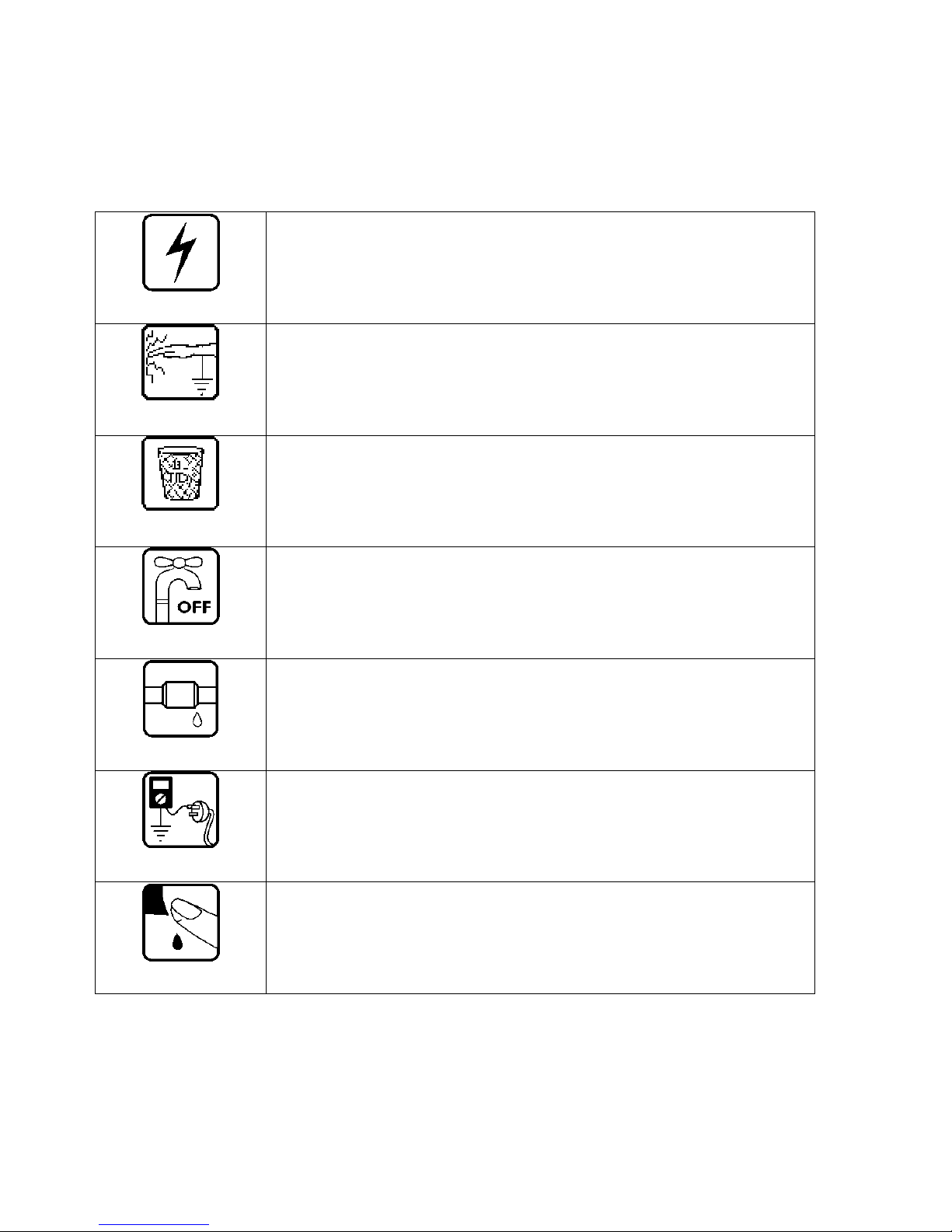
Electrical Safety
Ensure the mains power has been disconnected before servicing the
washer.
If the mains supply is required to be on to service the washer, make sure it
is turned off when removing any electrical component or connection to
avoid electric shock.
Electrostatic Discharge
An anti-static strap is to be used as electrical static discharge (ESD)
protection when servicing electronic components.
Good Working practices
Ensure the work area is in a tidy and orderly condition at all times so as
not to cause a hazard while service work is being completed. Always clean
and tidy the washer and work area after service is completed.
Isolate Water Supply
Turn off the water connection taps before servicing
Water Leak Check
Check for water leaks as part of the testing after the service has been
completed.
Insulation test
Megger test to check insulation
Warning: short together the phase and neutral pins on the plug so not to
damage any electronic circuitry.
Sharp Metal Edges
When working around cut sheet metal edges, use appropriate gloves or
protection to eliminate the change of receiving a laceration.

479602
7
2 SPECIFICATIONS
2.1 Dimensions
Height to lid
Open 55.5in – 56.6in / 1410mm – 1440mm
Closed 37.4in – 38.5 / 950mm – 980mm
Height to console 39.7in – 41.3in / 1010mm – 1050mm
Width 25.5in / 650mm
Depth 25.5in / 650mm
Inlet hose length 47.24in / 1200mm
Packed weight 143.3lb / 60.5kg
Unpacked weight 114.64lb / 52.0kg
Note: Exact height of the machine is dependent on how far the feet are inserted into the
base of the machine.
2.2 Maximum Capacity (Full Load)
Dry Weight 17.6lb / 8kg
2.3 Water Consumption
*Note: Approximate consumption for a high water level load for each rinse option offered.
Fill (High) 23.7 gal / 90 liters
Spray & Deep Rinse 34.3 gal / 175 liters
Water Save 39.6 gal / 150 liters
1 Deep Rinse 43.5 gal / 165 liters
2 Deep Rinse 56.79 gal / 215 liters
2.4 Water Fill Temperature (Approximate Factory Settings)
Supply Water Fill Temp
Hot 130
o
F / 60 oC
Hot / Warm 115
o
F / 50 oC
Warm 105
o
F / 40 oC
Warm / Cold 95
o
F / 35 oC
Cold Plus 60
o
F / 20 oC
Cold Supply temperature
Recommended hot water inlet temperature 149
o
F / 65 oC (Max)
2.5 Wash Motor
Electronically commutated 36 pole direct drive 3 phase brushless DC motor.
Motor Resistance @68
o
F (20oC): 19.5Ω +/- 10% (39Ω +/- 3.95Ω across any two phases)
2.6 Pump Motor
Part Number Voltage Frequency Resistance
420325P 110V AC 60Hz 7Ω +/- 8% @ 68
o
F / 20oC
Note: Thermal cut-out fitted
479602
8
2.7 Water Valves
Supply Mode of Operation Voltage Resistance Flow Rate
Cold Digitally Operated 24V DC 64Ω @ 68
o
F / 20oC 4.2 Gallons per minute
Hot Digitally Operated 24VDC 64Ω @ 68
o
F / 20oC 3 Gallons per minute
Note: Flow rate will vary slightly depending on pressure.
Operating pressures: Maximum 150psi / 1034 kPa - Minimum 5psi / 34 kPa
Note: Pressures below 5psi / 34kPa can create seating problems with the internal
diaphragm of the valve, and may cause water to drip into the inner basket when the
machine is not in use.
2.8 Recirculating Valve
Supply Mode of Operation Voltage Resistance
Recirculates Wax Solenoid 160V DC 1.7KΩ @ 68
o
F / 20oC
2.9 Thermistor
NTC-type temperature sensor (Thermistor) Resistance 10KΩ @ 77oF / 25oC
2.10 Cabinet
Pre-painted steel
2.11 Lid
ABS plastic
2.12 Top Deck
Polypropylene
2.13 Inner Basket
Stainless steel: Grade 430T
Basket base and balance ring: Polypropylene
The inner basket on the large machine has a
series of small bumps around the base of the
inner basket. These bumps are designed to
improve wash performance by increasing load
turnover and movement.
Note: The inner basket is backwardly
compatible with all earlier large machines.
479602
9
Inner Basket Weight
Large 23.10lb +/- 9.7oz / 10.480kg +/- 275g
Inner Basket Speed Heavy Duty Regular Delicate Allergy Permanent Press
Fast Spin 1,000 RPM 1,000 RPM N/A 1,000 RPM 1,000 RPM
Medium Spin 670 RPM 670 RPM N/A 670 RPM 670 RPM
Slow Spin 300 RPM 300 RPM 300 RPM 300 RPM 300 RPM
Stir Speed 25 RPM 25 RPM 25 RPM 25 RPM 25 RPM
2.14 Outer Tub
Aluminium insert over-moulded with polypropylene
2.15 Console
ABS plastic with ABS plastic insert for display module.
2.16 Agitator
Polypropylene
2.17 Fabric Softener Dispenser
Dosage 75cc
2.18 Electric Supply
Operating Voltage 110/120V AC 60Hz
Maximum Current 7.0 amps
2.19 User Information
User Guide 478183
2.20 Lid Lock
Resistance 63Ω +/- 10% @ 68oF / 20oC
Note: Normally low voltage, potentially 110V if harness is grounded on the cabinet!
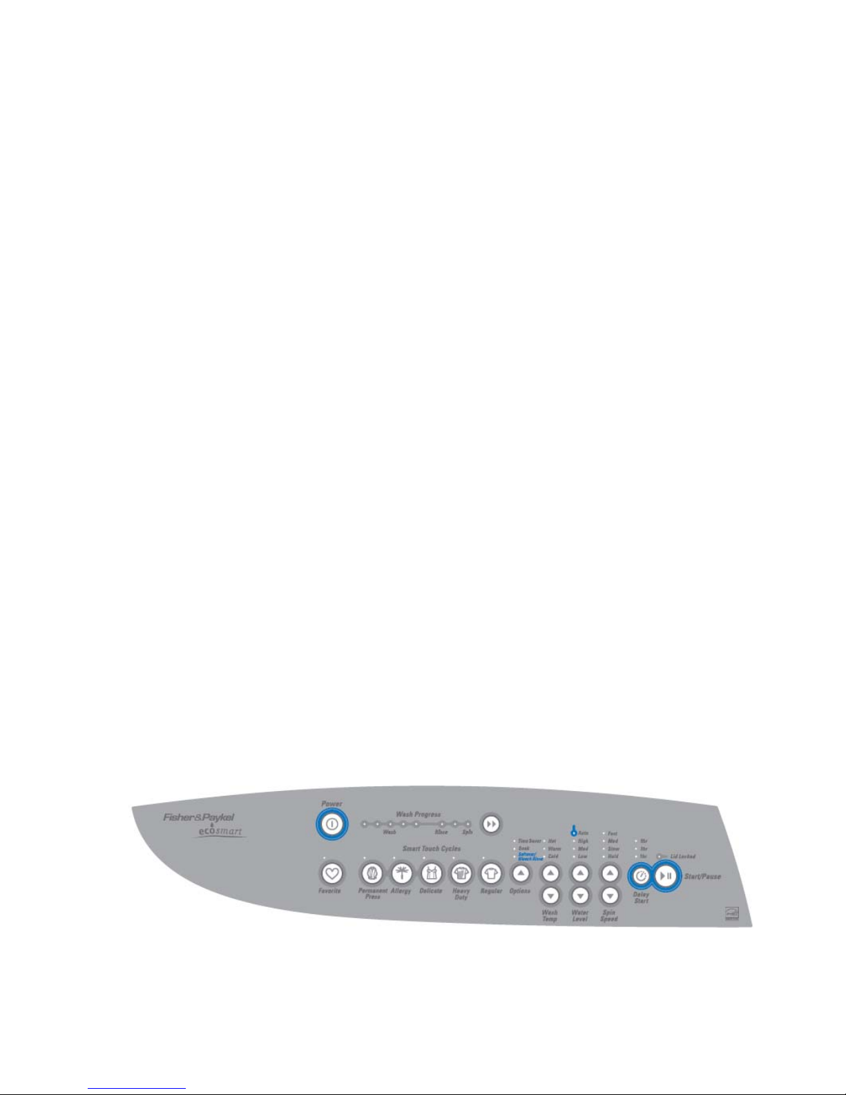
2.21 Control Panel – (EcoSmart)

479602
10
3 TECHNICAL OVERVIEW
This Service Manual contains information on the Product Specifications, Diagnostic Mode, Detailed
Fault Codes and the complete disassembly and assembly instructions for the washing machine.
3.1 Electronics
3.1.1 Motor Control Module
The Motor Control microprocessor performs a wide variety of tasks. Primarily it controls the
electronic switching hardware to control the three phase currents in the Smart Drive DC motor.
The micro can accurately control not only the velocity of the motor but also the acceleration. This
accurate control is required to perform all the different agitator profiles, or wash actions, that are
used for caring for clothes. The Motor Control module performs the functions of fill, wash, drain
spray rinse and spin, when commanded to by the Display.
The Motor Control module microprocessor has a wide range of control with great accuracy over
water level, fill temperature, agitate action and spin speed. Having such control insures the wash
cycle selected provides the optimum soil removal combined with appropriate gentleness for the
washing and care of the clothes load.
The Motor Control Module for this Washer is air-cooled.
This Motor Control Module is not inter-changeable with other any other Series of machine.
Identification
The Motor Control module also has a white label attached to the top of the housing stating P9ECO
(Phase 9, Conventional Pump Eco).
Motor Control Module
Note: When replacing a Motor Control Module ensure that the pressure tube is clear of any
water droplets before operating the machine on a fill cycle. If the basket is full of water
drain the water then blow down the tube before reconnecting the pressure tube.
Ensure you have checked the resistance of all components going to the controller such as
pump, water valves, etc. otherwise controller will short and fail.
3.1.2 Display Module
The Display Module provides the link between
the washing machine electronics and the user.
Input on wash type, water level, spin speed,
start/stop and wash cycle time is given by the
user via the display push buttons.
Feedback on selection is given to the user by
Light Emitting Diodes (LEDs). Sound effects
accompany button presses.
479602
11
3.2 Stand By Mode
If the machine has not received any instructions for 10 minutes after being switched on at the
power point, or after completing the cycle, it will automatically go into a low power “Stand By”
mode. The control panel will be blank as if it was powered off at the wall.
Before entering the Diagnostic or Option Adjustment modes, the machine must be taken out of the
Stand By mode. To do this, the POWER button will have to be pressed, or the machine turned off
and back on at the mains supply point.
3.3 Out of Balance Detection – ‘Bump Detect’
On this machine the Out of Balance detection, is undertaken with electronic sensing, known as
‘Bump Detect’. ‘Bump Detect’ is software written into the Motor Control Module, which looks at
specific feedback from the Motor.
No fault codes are associated with ‘Bump Detect’, and there are no hard and fast tests that can be
carried out.
If a machine continually goes into an out of balance condition then the following needs to be
checked in the order given.
1. Even distribution of the wash load.
2. Ensure that the corner cabs are clear of the floor & machine is sitting on its feet.
3. Ensure that the machine is both level and stable on the floor with feet inserts fitted.
4. Check the weight of the inner basket (23.10 +/- 9.7oz / 10.480kg +/- 275g).
Note: If the OOB problem persists after checking the above, we would then recommend
replacing both the suspension rods and the rotor. It is highly unlikely that the Motor
Control Module will be the cause.
3.4 Water Temperature Sensing
The thermistor for sensing water temperature is
located in the back of the outlet elbow on the
valve assembly, and is connected directly to the
Motor Control Module.
For details on the wash temperature adjustment
Refer to the Use & Care manual.
Specifications
NTC-type temperature sensor (Thermistor)
Resistance 10KΩ @ 77
o
F / 25oC.
3.4.1 Controlled Cold
CONTROLLED COLD OPTIONS
Light color
Green = controlled cold
Amber = uncontrolled cold
This machine is designed for installations that
have both hot and cold water. To ensure
optimum performance even in very cold
weather, the cold-water temperature is
controlled to 60
o
F (20 oC). However if for some
reason you do not have hot water available you
may need to change to uncontrolled cold in very
cold weather.
The machine leaves the factory with the Controlled Cold Option set. To change this settings enter
the Option Adjustment mode and press the ADVANCE button once. Refer to the Use & Care
manual for the various options adjustments available.
479602
12
To enter the option adjustment mode:
1. Plug the machine in but do not press POWER.
2. Press and hold the Start / Pause button, then press the Power button
3. Three quick beeps will be heard and the machine will show an unusual pattern of lights.
4. Carry out any option adjustments necessary.
Refer to the Use & Care manual for the various options adjustments available
5. Press POWER to return to normal mode.
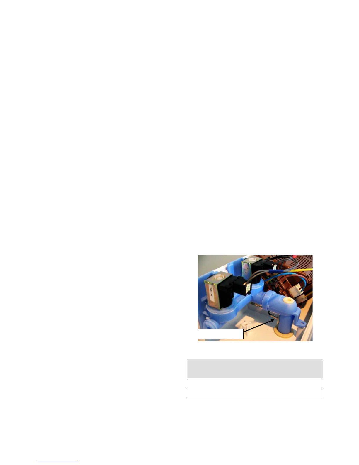
3.5 Water Valves
The machine uses a dual valve block assembly.
Independent coils control the hot and cold water
supply, which feeds the water through a
common outlet.
The valve block has a location feature for the
thermistor.
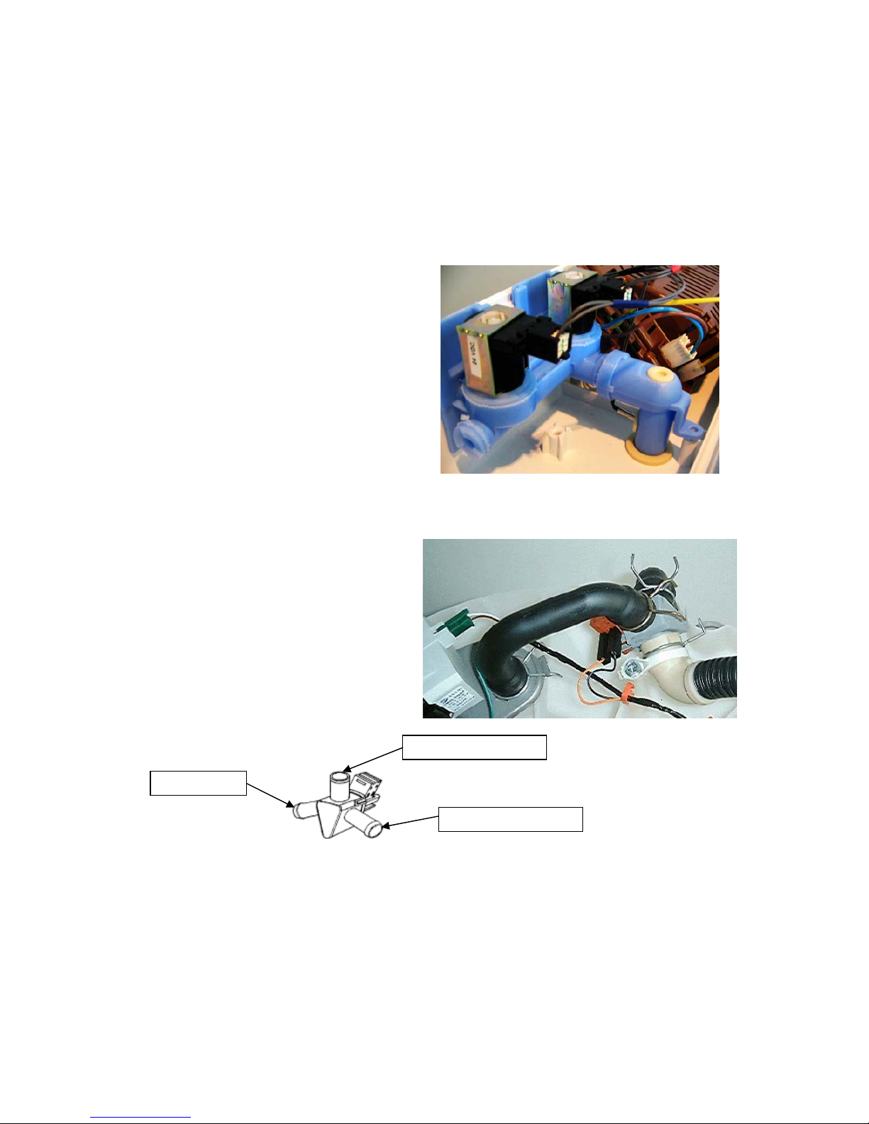
3.6 Recirculating Valve
The Recirculating Valve is situated at the
bottom of the Tub beside the Pump. It consist of
a wax solenoid which heats up and moves a
flapper to close off the drain enabling the water
to be recirculated back into the inner basket,
with the pump running. When powered on there
is 160 volts DC across the terminals.
NB: The Valve takes approximately 1 minute
to activate and 3 minutes to cool down and
return to its normal position.
479602
13
3.7 Water Level Measurement
The machine is fitted with a pressure sensor, which can control the fill to any water level. The
pressure sensor is incorporated within the Motor Control Module and cannot be removed. The
pressure tube connects from the Motor Control Module to the air bell at the bottom of the outer tub,
and is part of the harness assembly. Care must be taken when removing or refitting the pressure
tube to the pressure sensor as too much force can damage the device.
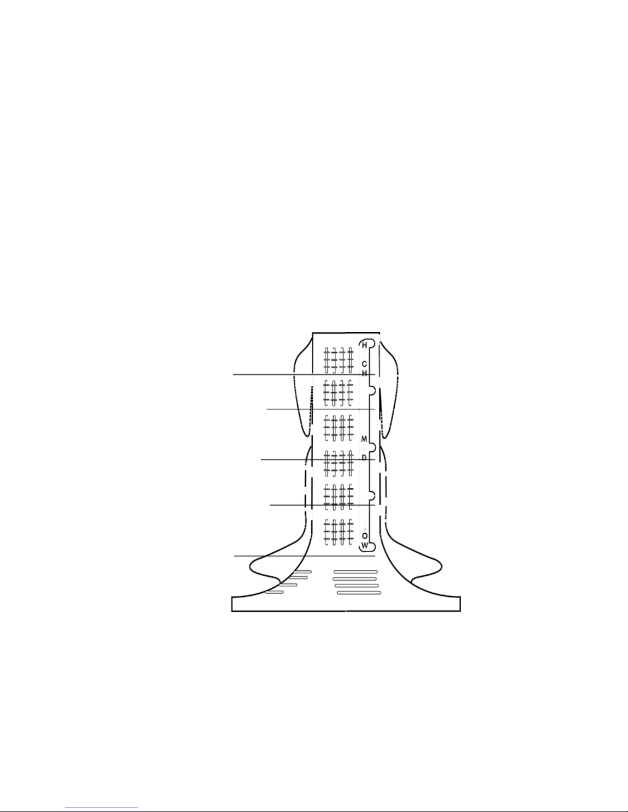
3.7.1 Manual Water Level
The agitator has 5 levels marked on its stem that can be used to help the user select the correct
water level. Select the correct water level by using the mark nearest to the top of the clothes.
The levels marked on the agitator are a guide for the clothes and do not correspond exactly to the
water level.
Occasionally water may be added during agitation. This is to maintain the water level due to the
release of air trapped in the garments.
For example: If the garments sat between the medium and high marks on the agitator, choosing a
medium water level would be better than choosing a high water level. Alternatively additional
garments could be added so that the garments were brought closer to the high mark.
Water Level Settings
Tolerance for each water level = +/- .59in / 15mm
High 2.12in / 54mm
Medium High 4.13in / 105mm
Medium 6.69in / 170mm
Medium Low 9.64in / 245mm
Low 11.81in / 300mm
479602
14
3.7.2 Auto Water Level
The machine automatically selects the appropriate water level for the load when AUTO Water
Level is selected, and will choose one of the pre-existing 5 water levels (low, medium low, medium,
medium high and high). During fill the machine pauses occasionally to sense the water level. The
machine checks if the water level is correct by using a series of 2 different agitate strokes. A slow
stroke to sense the load and an agitate stroke to mix the load. If the machine detects that the
water level is too low it will fill with more water and check the level again.
When washing an unusual load eg. large bulky garments, pillows, it is recommend that the
water level is manually selected.
Manually select the water level if there is already water in the basket.
If the machine does not fill to the correct level, the auto water level can be adjusted in the Option
Adjustment Mode. Refer to the Use & Care manual for the various options adjustments available.
To enter the option adjustment mode:
1. Plug the machine in but do not press POWER.
2. Press and hold the Start / Pause button, then press Power
3. Three quick beeps will be heard and the machine will show an unusual pattern of lights.
4. Carry out any option adjustments necessary.
5. Press POWER to return to normal mode.
3.8 Motor
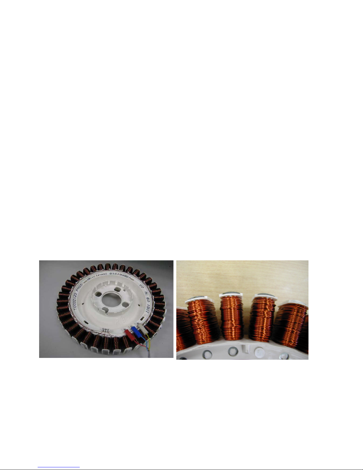
3.8.1 Stator
The stator used on this machine is unique to this series only and therefore it is not
interchangeable with any previous phase or series of machines. The stator has 36 poles with the
windings being Aluminium and is Identified by the printed marking AL 60 190T it looks the same as
the copper Stator but is 19.5 per winding.
Stator (36 Poles) Curved pole tips
Testing the Stator
If the stator needs to be tested we would first recommend testing the resistance of the windings at
the harness that is connected to the Motor Control Module. (Refer to Section
5.12).
Note: Ensure that the Rotor and basket are stationary when measurements are made.
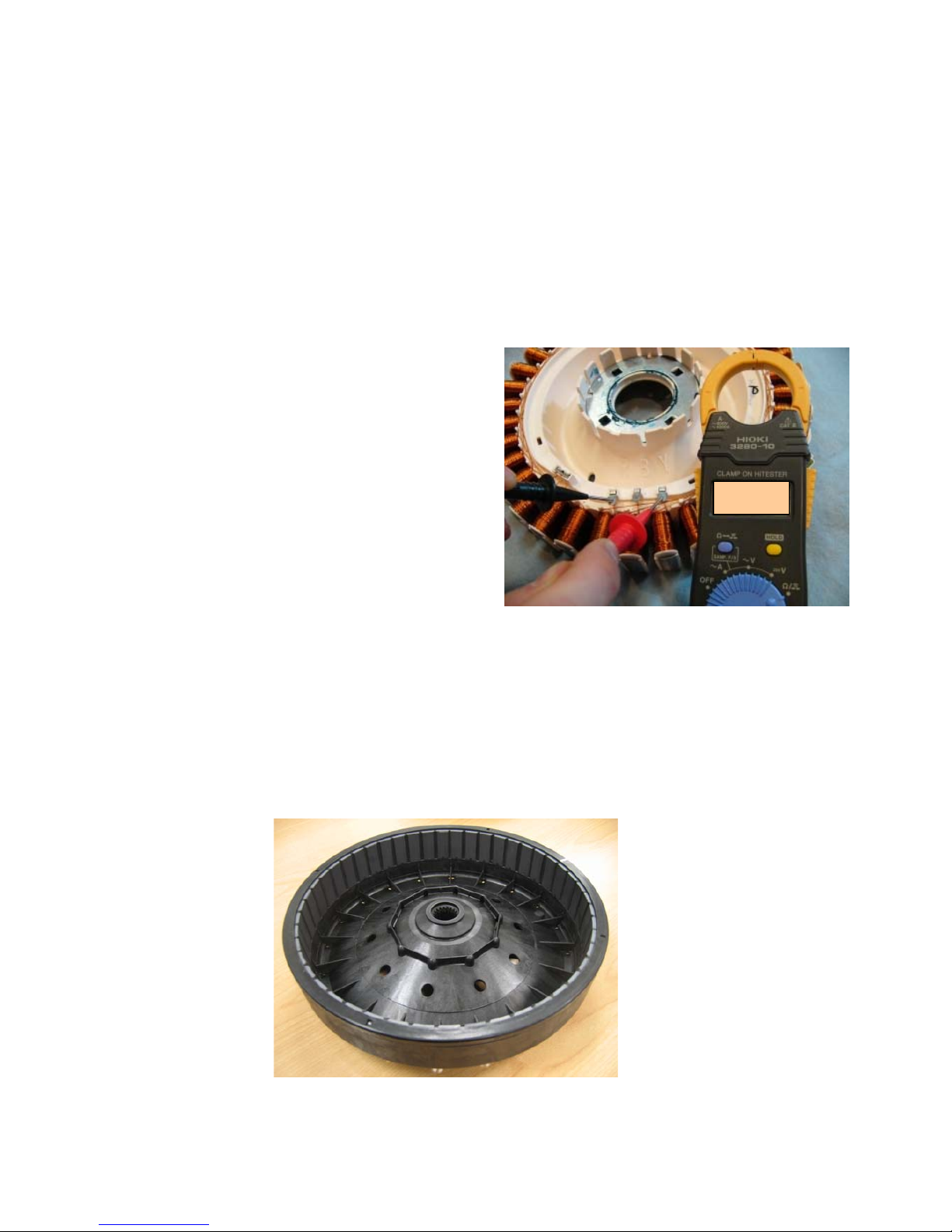
Testing the stator from the console
The resistance of each individual winding is approximately 19.5, however when testing the stator
from the console we are testing across two windings therefore the resistance should be
approximately. 39 +/- 10%.
479602
15
To test all windings you will need to measure across:
Red & Blue
Red & Yellow
Blue & Yellow
If the meter shows an incorrect reading we would then recommend testing the stator from
underneath the machine as there could be a fault in the wiring harness. To test the stator, remove
the rotor and stator. Refer to Sections
8.17 and 8.18.
Note: Two clamp plates are used to secure the Stator, one on each side. The four bolts are
tightened to a torque of 5Nm. The plastic bolt for securing the Rotor requires a 16mm
socket and should be tightened to 8Nm.
Testing the Stator
After removing the Stator, it can now be tested.
Test points are:
R (Red) / B (Blue)
B (Blue) / Y (Yellow)
Y (Yellow) / R (Red)
The value should be approx. 39 +/- 10%
across any of the two windings.
3.8.2 Rotor
The rotor is also unique to this machine. It has 48 blocks of individual magnets in a black
moulding.
The rotor is not interchangeable with any previous phase or series of machine.
The rotor can physically be interchanged, however electrically they are incompatible.
The photograph below shows the Rotor used.
Black
39.0
Ω
479602
16
3.9 Pump
The pump is coupled directly to the outer tub.
This eliminates tub to pump hoses and the
accompanying seals, clips etc. The pump
housing is an integral part of the outer tub.
When removing the pump up to a 1/3 of a
Gallon of water may leak from the pump cavity.
When refitting the pump; lubricate the seal face
with liquid soap or detergent (do not use
grease).
Blocked Pump Detection
This is achieved by monitoring the water level
during drain. If the water level has not dropped
by approximately 1/8” within a predetermined
time period (approximately 9-10 minutes), then
the product will report a blocked pump fault.
Note: The Resistance of the pump should
read 7Ω +/- 8%. (Refer to section
2.6)
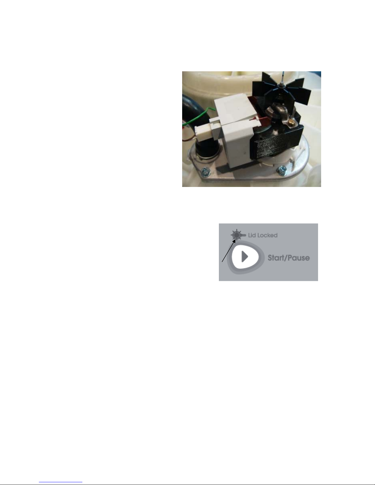
3.10 Lid Lock
The Washer uses a lid lock to secure the lid closed, which is
locked for the entire cycle. When locked the Lid Locked LED
will illuminate. Once the spin has completed, the lock will
release and the lid can be opened. To open the lid during
the cycle the START/PAUSE button must be pressed, the
machine will come to a halt, and the lid locked LED will
extinguish.
If the lid is left open, the machine will be unable to lock the lid
and the cycle will be halted. The machine will play a tune
and the lid lock will flash until the lid is closed and the
START/PAUSE button is pressed.
If the lid-lock fails in the closed position, the locked lid can be forced upwards and out of the
lock. Note: This is the only time in which we would recommend doing this as this action
will DAMAGE the lid lock which will need replacing and the lid tang will need to be
inspected for damage.
If the harness is damaged, the complete lid lock assembly will need to be replaced.
If the power supply is cut during the spin cycle, the machine will keep the lid locked until the rotor
has ceased to turn (3 to 10 secs). Only then will it release the lock. The motor is acting like a
generator and allows the lock to stay energized under the baskets inertia.
In a brown out situation, the machine will restart at the beginning of the section of the cycle it was
on and continue the wash. The lid lock would then be reactivated.
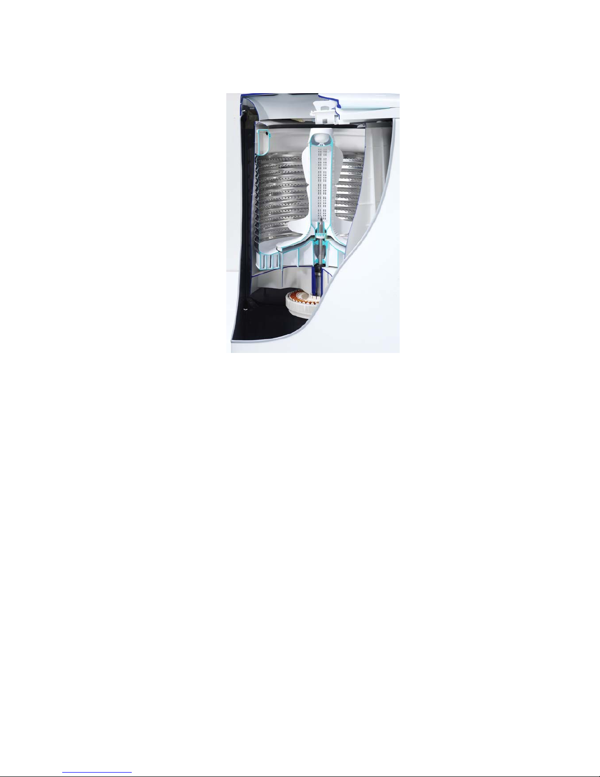
3.11 Inner Basket and Outer Tub
The outer tub is the assembly to which all the motor, pump system, suspension rods, etc are
mounted. Within the outer tub is the inner basket and the agitator. During spin, the agitator and
inner basket have to be coupled together and turn as a single unit. In agitate; the agitator and
inner basket are free to rotate independently.
479602
17
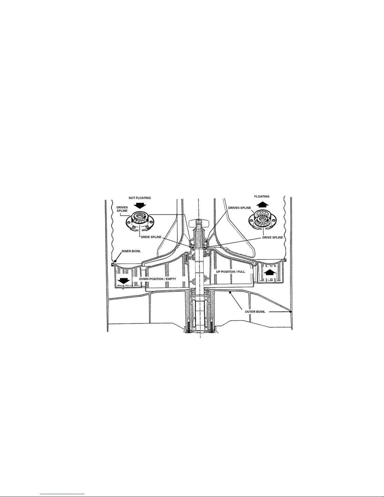
The inner basket is free to move in a vertical direction. The position of the inner basket is
determined by the water level. At the base of the inner basket is a flotation chamber consisting of
a number of individual cells. When the machine is filling with water, the pressure on the air in
these cells increases as the water level rises until eventually the inner basket floats upwards and
disengages the driven spline from the drive spline. This action frees the agitator from the inner
basket and allows it to move freely in both directions.
When the water is draining, the pressure on the air trapped in the cells of the flotation chamber
decreases allowing the inner basket to settle back down onto the drive spline and re-engage the
driven spline, thus allowing the agitator and inner basket to turn as one unit. The floating basket is
also used to detect if the user has selected the correct water level for the size of the clothes load.
The point at which the basket starts to float is determined by the water level and the size of the
load. The greater the load, the more water is needed before the inner basket will float. By
detecting the point at which the basket floats, the machine can determine whether the correct
water level for the particular clothes load has been chosen by the operator. If the operator has
chosen a level that is too low for the load, the machine will override that choice and fill to the
correct level. This is to ensure optimum wash performance and minimal clothes wear. If the user
has selected a level that is higher than necessary, the machine will still fill to the users selected
level.
3.11.1 Detection of Inner Basket Float off Point – Basket Check
During fill the inner basket will rotate to ensure that the clothes are evenly saturated with water.
When the chosen water level is reached, and before the agitate cycle is started, the machine will
carry out inner basket float checks (basket check). The inner basket will stop and commence a
number of small agitate type actions. During this action the machine determines if the inner basket
has floated. If it has the machine will determine the required water level and check if the operator
has selected the correct level. If the inner basket has not floated, the machine will continue filling
and check again later. The water level at which the inner basket floats is not necessarily the same
as the final water level.
3.11.2 Detection of Inner Basket Re-Engagement – Basket Check
After the water has drained, the inner basket will sink down and re-engage onto the drive spline.
To ensure the inner basket has re-engaged correctly, the machine will carry out a basket reengage test sequence (basket check). Basket check consists of a series of short agitate type
actions before the spin cycle starts. A sound may be heard as the inner basket re-engages.
479602
18
3.11.3 Balance Rings
The inner basket has 2 balance rings, one at the top, and one at the bottom. These are sealed
compartments half full of water. This water allows the basket to balance. If one or both of these
rings have lost water then the inner basket must be replaced. The easiest way to determine a loss
of water is to weigh the baskets on an accurate set of scales.
Inner Basket Weight: 23.10lb +/- 9.7oz / 10.480kg +/- 275g
3.12 Agitator
The agitator design differs from conventional designs in that it is made of very flexible plastic that
bends and flexes as the clothes are moved around the basket. The agitator action is similar to that
of a fish moving through the water, so the side-wards motion is translated to forward thrust. This
is not only more forgiving on the clothes but helps to slowly move the clothes around the basket in
a toroidal motion, i.e. a vertical circular motion. The fins at the top of the agitator pull the clothes
on the surface of the water inwards and then push them downwards. The bottom fins then push
the clothes towards the outside of the basket again and back up to the surface.
The agitator also features guides on the side to help the user choose the correct water level for
each load size. The guides relate to the level that the dry clothes come up to, which relates back
to the correct water level. The agitator also gives the user information when measuring detergent,
to ensure that they dose correctly for the load size.
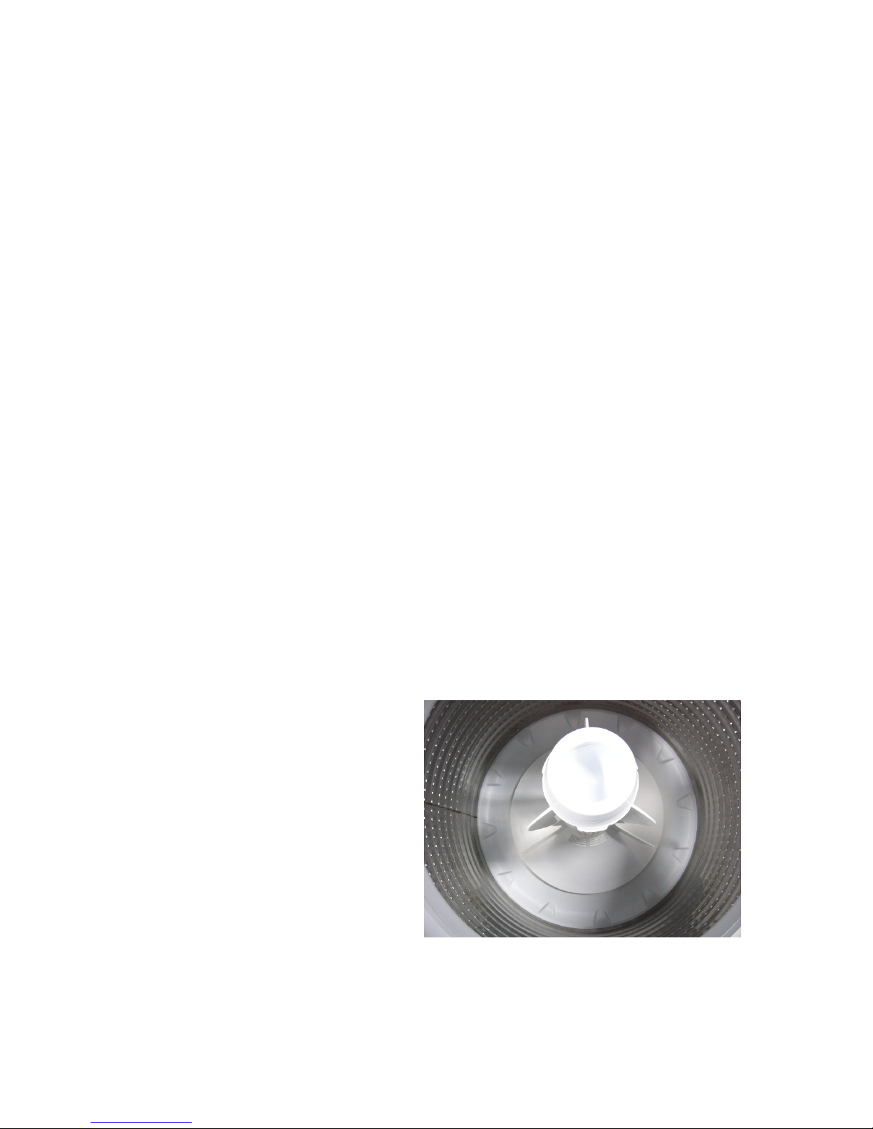
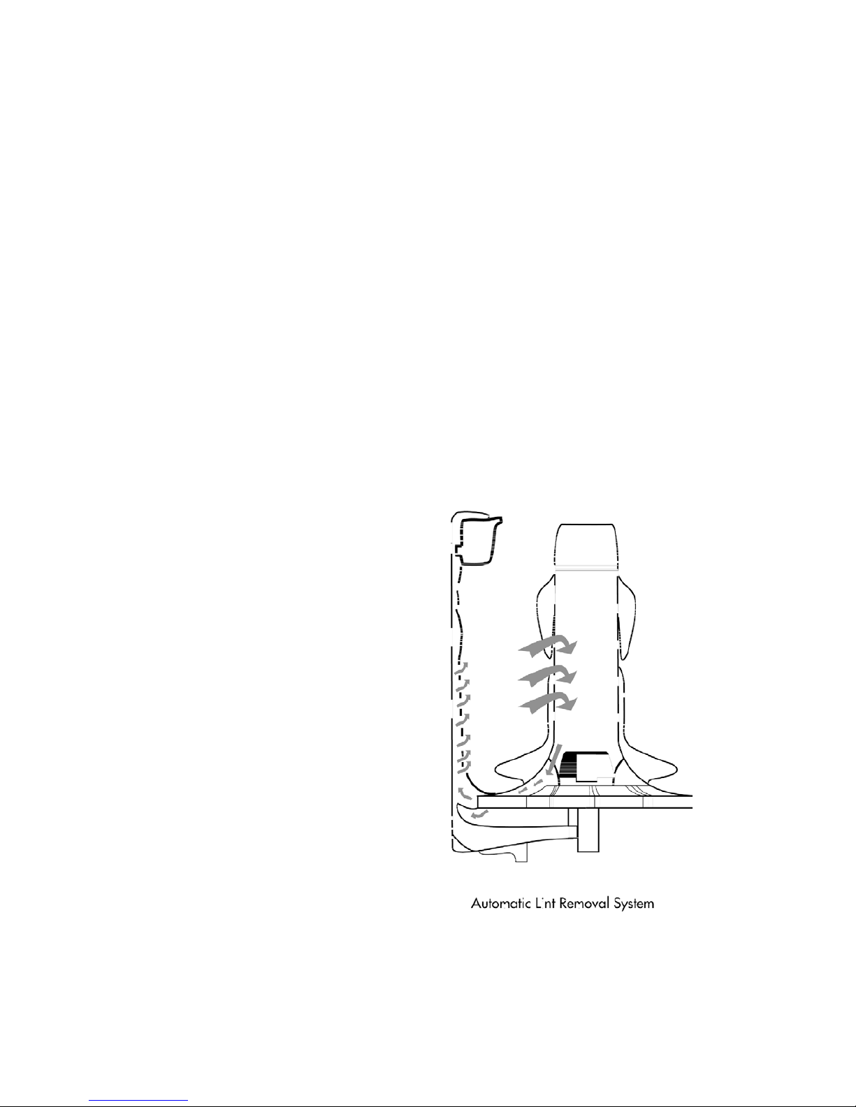
3.13 Lint Removal System
The machines self cleaning lint removal system
works by continuous water circulation, resulting
in the separation of lint from the wash water. As
the agitator moves, the specially designed
vanes on the bottom create turbulence. The
agitator acts as a centrifugal pump, circulating
the wash water.
As a result of the agitator action, lint and wash
water are sucked into the agitator stem and
down to the base where they are directed into
the cavity between the inner basket and outer
tub. The extruded holes of the inner basket are
shaped to allow the wash water to flow back into
the basket, but prevent the lint from following.
The lint then floats to the surface of the water
between the inner and outer basket and
remains there until it is flushed out the drain at
the end of the wash cycle.
 Loading...