


Fisher & Paykel WH1060P1 User Manual

FRONT LOADING CLOTHES WASHER
WH1060P model
INSTALLATION GUIDE/USER GUIDE
NZ AU


CONTENTS
Introduction 3
Safety and warnings 4
Installation instructions 5
Before your first wash 13
Safety features 14
Control panel 15
Detergent and softener dispenser 17
Getting started quickly 18
Wash cycles 19
Wash preparation 20
Customising wash cycle 23
Caring for your washer 26
Before you call for service 29
Fault codes 31
Troubleshooting 32
Manufacturer’s Warranty 37
Customer Care 39
IMPORTANT!
SAVE THESE INSTRUCTIONS
The models shown in this User guide may
not be available in all markets and are
subject to change at any time. For current
details about model and specification
availability in your country, please go to
our website fisherpaykel.com or contact
your local Fisher & Paykel dealer.
Registration
Register your product with us so we can
provide you with the best service possible.
To register your product visit our website:
fisherpaykel.com
1


INTRODUCTION
Welcome
Thank you for buying a Fisher & Paykel clothes washer. We are proud of this washer
andtrust it will serve you well for many years.
At Fisher & Paykel, we aim to provide innovative products that are simple to use,
ergonomic and environment-friendly. Your washer has numerous wash cycles and
options so you can perform every wash task with ease and the knowledge your
clothesare receiving the best possible care.
Please take the time to read these instructions carefully before you begin using
yourwasher.
Follow the instructions in this User guide to ensure you get the performance you
expectfrom your washer and the best possible wash results. Keep this manual for
futurereference.
We hope you enjoy your new washer. We have certainly enjoyed designing it for you.
Front loading washer model
3

SAFETY AND WARNINGS
!
WARNING!
Electric Shock Hazard
If you are using an extension cord or a portable electrical outlet device
(egmulti-socket outlet box), ensure that it is positioned so that it does
notcome into contact with water or moisture.
Failure to do so may result in death or electrical shock.
IMPORTANT SAFETY INSTRUCTIONS
WARNING! When using your clothes washer, follow basic precautions, including
thefollowing:
This clothes washer is not intended for use by persons (including children)
withreduced physical, sensory or mental capabilities, or lack of experience and
knowledge,unless they are supervised or given instructions on how to use the
washerby someone responsible for their safety.
The washer should only be used for washing and rinsing of textiles where this is
indicated on the care label.
The door will be locked from the start of the cycle until the cycle is complete
for safety reasons. It is possible to open the door during the cycle under certain
conditions (refer to page14).
Never force the door open.
Keep children away from the washer while it is in operation.
Supervise children to ensure they do not play with the washer or climb inside the
drum.
Do not touch the glass part of the door during a cycle as the door can become hot.
Do not open the detergent dispenser during the cycle as hot water may come out
ofit.
The only user-removable parts of the washer are the inlet hose(s), detergent dispenser
and the pump filter. No other parts are designed to be removed by anyone other than
a Fisher & Paykel trained and supported service technician.
When disposing of the washer, it is recommended that the door is removed
toavoidchildren getting trapped inside, and that the electrical cable is cut off
closeto the washer.
Do not add petrol, dry-cleaning solvents, or other flammable or explosive substances
to the wash water. These substances give off vapours that could ignite or explode.
Do not wash articles that have been previously cleaned in, washed in, soaked in,
or spotted with gasoline, dry-cleaning solvents, or other flammable or explosive
substances as they give off vapours that could ignite or explode.
4
INSTALLATION INSTRUCTIONS
Accessories
Please check if you received the following accessories with your Fisher&Paykel washer.
You will find them inside the drum or attached to the packaging.
2 x Inlet hose(s)
1 x Inlet valve cap
1 x Drain hose guide
1 x Installation guide and User guide
1 x Spanner
1 x Installation leaflet (attached to the top of the washer)
Unpacking
To ensure the best performance from your new washer please follow the instructionsbelow.
Removing the packaging
Remove the outer packaging (including the expanded polystyrene packer and plastic
1
wrapping). All packaging must be removed prior to use. Ensure these materials are
kept out of reach of children. Note: a small amount of water may be seen inside the
packaging and inside the washer. This is the result of factory testing and is normal.
Tilt the machine backwards and ‘walk’ it off the base one foot at a time. Not doing so
2
may cause damage to your floor and washer.
Remove all packaging and accessories from inside the drum.
3
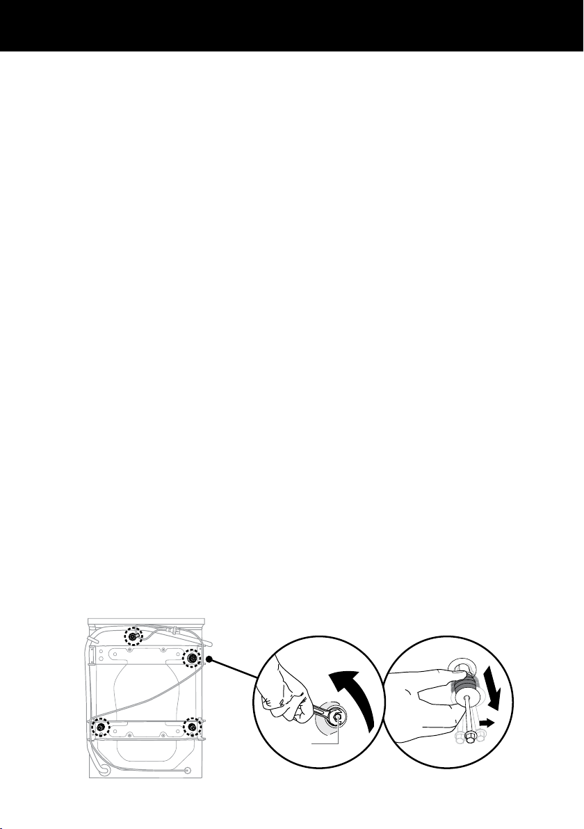
Removing transit safety bolts
The clothes washer is fitted with transit safety bolts at the rear to avoid possible damage
to the interior during transportation.
IMPORTANT!
The transit bolts MUST be removed prior to operation of the machine.
Failure to remove these will result in damage to the machine.
Note: the transit bolts MUST be removed in order to use the power cord.
To remove the bolts
Use a spanner or socket to unscrew and remove all 4 transit bolts at the back of the
1
washer(A).
Pull the black rubber grommets to remove the bolt, grommet and white plastic spacers
2
from the machine (B). Retain these for future use.
A
Removing the transit safety bolts
B
5

Detach the drain hose
3
from the plastic clasp, and
remove the clasps on the
side of the transit braces.
Remove the 12 transit brace
4
screws from the left and
right sides, and near the
centre of top and bottom
braces (refer to C).
Remove the braces (refer
5
toD). Keep the braces and
screws for future use.
INSTALLATION INSTRUCTIONS
Removing the drain hose
C
D
Pull out the two transit rods
6
located below the two lower
transit bolt holes (refer to E).
Remove the yellow safety clip
7
from the power cord.
Cover the transit bolt holes with
8
the plastic plugs (provided).
Pushto clip into place (refer to F).
6
Removing the bracesRemoving the transit brace screws
E
Removing the transit rods
F
Covering bolt holes with plastic plugs
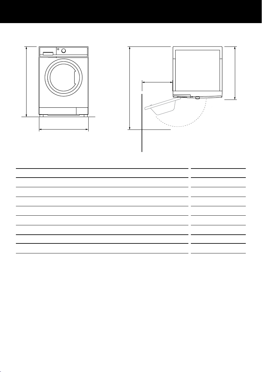
Product dimensions
A
C
INSTALLATION INSTRUCTIONS
D
E
B
FRONT VIEW
Wall
PRODUCT DIMENSIONS mm
Overall height of product 850
A
Overall width of product 600
B
Overall depth of product (including dial and door whenclosed) 665
C
Depth with door open 1110
D
Minimum door clearance to adjacent wall 340
E
Standpipe height min. 800–1200
MAXIMUM CAPACITY kg
TOP VIEW
10
Note: the exact height of your washer is dependent on how far the feet are extended
from the base of the machine. The space where you install your washer needs to be at
least 40mm wider and 20mm deeper than its dimensions.
Electrical supply: 220 – 240V, 50Hz Sinusoidal, minimum 10A.
Inlet water static pressure: Max. 1MPa (150psi), Min. 30kPa (4.5psi).
Inlet water flow rate at tap: Min. 6litres/min.
7

INSTALLATION INSTRUCTIONS
Location
IMPORTANT!
Install the machine on a solid and level floor surface ensuring it has at least 20mm
clearance on each side. The washer must not be installed on any soft or textured floor
coverings (eg carpet, rugs).
Note: This machine must not be installed and operated on a plinth.
Levelling the machine
It is IMPORTANT to level the machine to ensure good spin
performance, and to minimise noise, vibrations and wear
and tear on the washer.
Before positioning the machine in its final position, check
1
that the machine is level, front to back and side to side.
Adjust the product into its final position (we suggest a
2
minimum clearance of 20mm each side).
Use a spirit level to check that the machine is correctly
3
level. If needed, pull the machine out. Loosen the lock nut
using the spanner provided and wind the feet up or down
to correctly level the machine.
Using the spanner provided, tighten the lock nuts against
4
the base of the machine to lock the feet in position.
Locking the feet
Connecting to the water supply
Inlet hoses
IMPORTANT!
Use new hose sets provided with the washer to connect
the washer to the water mains.
Old hose sets should not be re-used.
We recommend the inlet hoses are changed every 5 years.
WARNING: Failure to do so may result in a flood and
damage to property.
Connect the straight ends of the inlet hoses to the taps.
1
Connect the elbow ends to the corresponding machine inlet valves.
2
Straight
(tap) end
Inlet hose ends
Thehotvalveiscoloured orange to make this easier.
Tighten the inlet hose ends by hand until the hose seal just makes
3
contactwiththetapsealingface. Continue to tighten a further half-turn.
Makesurethereare no kinks in the hoses.
Turn the taps on and check for leaks. Check for leaks again after 24hours.
4
IMPORTANT!
The hot water temperature should not exceed 65°C and the cold water temperature
not exceed35°C. Temperatures above these may cause the machine to fault or
causedamage to the machine.
8
Elbow
(machine) end

INSTALLATION INSTRUCTIONS
If you have an uncontrolled water heating source (eg a wet back or solar heating system)
you should fit a Hot ‘N’ Safe Valve. This will ensure the hot water temperature remains
within safe limits.
Hot ‘N’ Safe Valves available are:
RMC TVA 50HF
RMC TVA 75HFS
Adjustable between 35°C – 55°C
RMC TVA 50HP
For instantaneous gas hot water supply
Water supply requirements:
Inlet water pressure: Maximum 1MPa (150psi), Minimum 30kPa (4.5psi)
Inlet water flow rate: Minimum 6litres/minute
Cold supply only:
If you only have a cold water supply, the inlet valve cap (blanking cap) that came with
your washer must be connected to the hot inlet valve. The cap prevents water leaking
out of the hot valve. This appliance incorporates backflow protection complying with
IEC61770. No further backflow protection is required for connection to the water supply.
Note: Your washer has an internal heater to heat water. If you do not connect a hot
water inlet hose, your washer will automatically recognise there is no hot water supply
and its internal heater will heat the cold water to the selected cycle temperature.
9

INSTALLATION INSTRUCTIONS
Draining
Placing the drain hose in a stand pipe or tub
To guide the drain hose over the tub or
1
standpipe, the hose guide must be fitted to
the drain hose. The height of the standpipe or
tub should be between 800 – 1200mm.
Secure the hose guide so it cannot be
2
dislodged from the standpipe or tub.
IMPORTANT!
If the drain hose is placed on the ground or
if the standpipe or tub is less than 800mm
high, the washing machine will continuously
drain while being filled (siphon).
Regularly check that your standpipe or tub
is free from lint or other obstructions, which
may affect how your machine works or may
cause flooding.
Attaching drain hose to spigot
Guide the drain hose through the hose guide.
1
Secure the hose guide to the back wall of
2
cupboard using a screw. The height of the
drain hose should be between 500 – 800mm
from ground level.
Attach the drain hose to the spigot and
3
secure using a hose clamp to ensure the
blanking insert is cleared from the spigot.
Check for leaks.
4
Pull hose
through
guide
(20mm)
maximum
Standpipe 800 – 1200mm
Fitting the drain hose guide
Height 500 – 800mm
from ground
The drain hose should be checked from time
to time and replaced if any damage (egwear,
cuts, bulges, kinks, leaks, etc) is found.
Donotbend the drain hose sharply, as this
may cause it to split.
In multi-storey apartments or any upper floor,
the machine should be installed on a floor
equipped with a drain.
Draining must comply with local by-laws.
10
Attaching drain hose to spigot

INSTALLATION INSTRUCTIONS
Electrical connection
This appliance must be connected to a 220V – 240V, 50Hz, sinusoidal, minimum 10A
1
electricalsupply.
Release the power cord (transit bolts must be removed).
2
Remove and discard the plastic pin cover and plug into a wallsocket.
3
Connect the appliance to an earthed outlet protected by a fuse of suitable capacity.
4
Check the power cord for damage and make sure it is not squashed or twisted when
installing the washer.
Always remove the power cord from a socket by the plug, not by the cord.
IMPORTANT!
If you are using an extension cord or a portable electrical outlet device (eg multi-socket
outlet box), ensure that it is positioned so that it does not come into contact with water
or moisture. FAILURE TO DO SO MAY RESULT IN DEATH OR ELECTRICAL SHOCK.
Do not touch or operate the machine with wet hands or with bare-feet.
A damaged power cord must be replaced by a Fisher & Paykel trained and supported
service technician, in order to avoid a hazard. The appliance must not be operated
until it is repaired, as there is risk of electric shock.
Do not operate this machine if it has been damaged during transport. Contact your
Fisher&Paykel dealer or Fisher & Paykel trained and supported service technician.
SPARE PARTS
Available from your Fisher & Paykel dealer or a Fisher & Paykel trained and supported
service technician.
Hose Inlet Long (2m) Part No. 422680P
Hose Inlet Large Bore Part No. 426123P
Drain Hose Extension
(Not suitable for attaching to a spigot)
Part No. 425627P
11

INSTALLATION INSTRUCTIONS
Completing the installation
Installation test cycle
IMPORTANT!
Do this before you wash any items in your washer. This is to check that your washer
isinstalled correctly and that it is functioning properly prior to use. We recommend
todo an initial manual wash with a half dose of detergent.
Turn your washer on by pressing the ‘POWER’ button.
1
Select the ‘Quick’ or ‘Super Quick’ cycle. Ensure the drum is empty and the door closed.
2
Touch the button. The machine will start to fill.
3
Observe the machine for any problems (eg leaking from the hoses, excess noise
orvibrations).
The washer will beep and display any faults on the screen if there are any problems.
Refer to the ‘Before you call for Service’ section at the back of this book.
Continue to observe until you see water in the bottom of the drum.
4
Touch to pause the cycle, then press ‘POWER’ to turn the machine off.
5
Press ‘POWER’ again, select the ‘Spin’ cycle and touch .
6
Check that the drain hose is firmly secured to the standpipe or tub or spigot.
Observe that the machine pumps out the water and spins.
IMPORTANT!
If there are any problems, you must address these before proceeding with normal use.
The washer will automatically turn off at the end of the cycle if there are no problems.
12
 Loading...