

Computer Numerical Controls
GE Fanuc Aut omation Eu r ope
Laser C Series
Operator‘s Manual
B
4
/
0
N
E
4
1
1
0
7
-
TECHNOLOGY AND MORE


• No part of this manual may be reproduced in any form.
• All specifications and designs are subject to change without notice.
The products in this manual are controlled based on Japan’s “Foreign Exchange and
Foreign Trade Law”. The export from Japan may be subject to an export license by the
government of Japan.
Further, re-export to another country may be subject to the license of the government of
the country from where the product is re-exported. Furthermore, the product may also be
controlled by re-export regulations of the United States government.
Should you wish to export or re-export these products, please contact FANUC for advice.
In this manual we have tried as much as possible to describe all the various matters.
However, we cannot describe all the matters which must not be done, or which cannot be
done, because there are so many possibilities.
Therefore, matters which are not especially described as possible in this manual should be
regarded as ”impossible”.
This manual contains the program names or device names of other companies, some of
which are registered trademarks of respective owners. However, these names are not
followed by ® or ™ in the main body.
B–70114EN/04
PREFACE
PREFACE
This document describes the following models.
Model Abbreviation
FANUC LASER–MODEL C1500B C1500B
FANUC LASER–MODEL C2000B C2000B
FANUC LASER–MODEL C2000C C2000C
FANUC LASER–MODEL C3000C C3000C
FANUC LASER–MODEL C3000D C3000D
FANUC LASER–MODEL C4000A C4000A
FANUC LASER–MODEL C6000B C6000B
p–1
PREFACE
B–70114EN/04
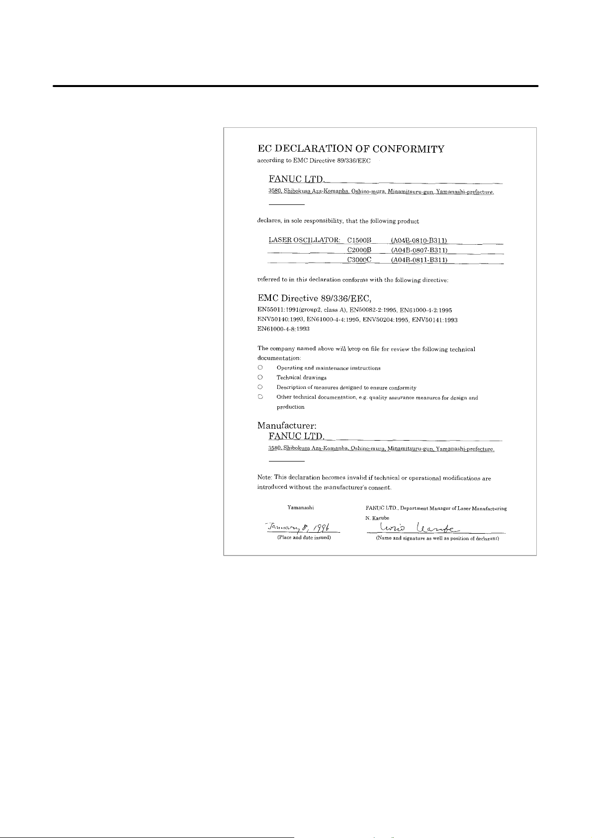
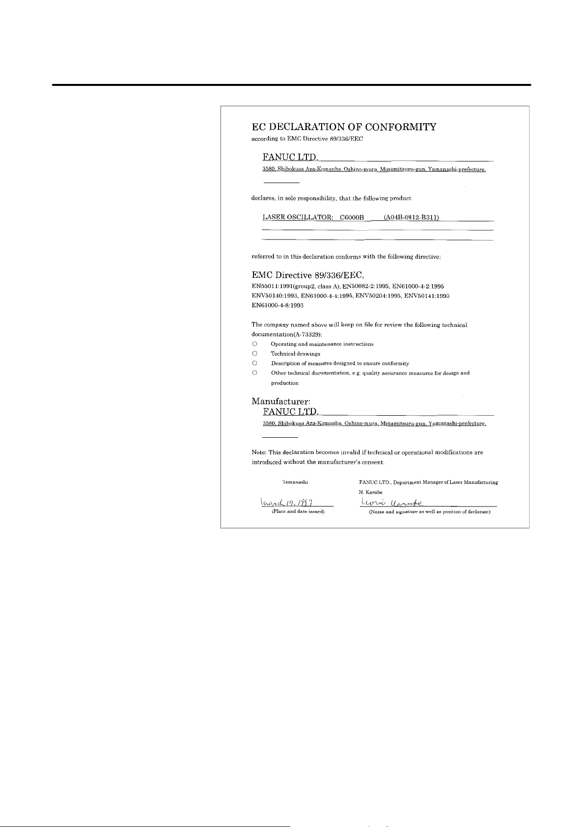
And, these models conform with EMC Directive 89/336/EEC.
401-0597 Japan
401-0597 Japan
p–2
B–70114EN/04
PREFACE
401-0597 Japan
401-0597 Japan
p–3
PREFACE
B–70114EN/04
401-0597 Japan
401-0597 Japan
p–4
B–70114EN/04
PREFACE
p–5
PREFACE
B–70114EN/04
p–6

B–70114EN/04
Table of Contents
PREFACE p–1. . . . . . . . . . . . . . . . . . . . . . . . . . . . . . . . . . . . . . . . . . . . . . . . . . . . . . . . . . . . . . . . . . .
1. OVERVIEW 1. . . . . . . . . . . . . . . . . . . . . . . . . . . . . . . . . . . . . . . . . . . . . . . . . . . . . . . . . . . . . . . . . .
1.1 MANUAL CONTENTS 2. . . . . . . . . . . . . . . . . . . . . . . . . . . . . . . . . . . . . . . . . . . . . . . . . . . . . . . . . . . . .
1.2 APPLICABLE MODELS 3. . . . . . . . . . . . . . . . . . . . . . . . . . . . . . . . . . . . . . . . . . . . . . . . . . . . . . . . . . .
1.3 RELATED MANUALS 3. . . . . . . . . . . . . . . . . . . . . . . . . . . . . . . . . . . . . . . . . . . . . . . . . . . . . . . . . . . . .
1.4 FOR SAFE OPERATION 4. . . . . . . . . . . . . . . . . . . . . . . . . . . . . . . . . . . . . . . . . . . . . . . . . . . . . . . . . . .
1.5 NOTES ON READING THIS MANUAL 4. . . . . . . . . . . . . . . . . . . . . . . . . . . . . . . . . . . . . . . . . . . . . . .
2. SAFETY 5. . . . . . . . . . . . . . . . . . . . . . . . . . . . . . . . . . . . . . . . . . . . . . . . . . . . . . . . . . . . . . . . . . . . .
2.1 LASER BEAM 6. . . . . . . . . . . . . . . . . . . . . . . . . . . . . . . . . . . . . . . . . . . . . . . . . . . . . . . . . . . . . . . . . . . .
2.2 HIGH VOLTAGE 11. . . . . . . . . . . . . . . . . . . . . . . . . . . . . . . . . . . . . . . . . . . . . . . . . . . . . . . . . . . . . . . . .
2.3 SAFETY ENCLOSURE (AT YOUR WORK STATION) 19. . . . . . . . . . . . . . . . . . . . . . . . . . . . . . . . . .
2.4 FIRE 19. . . . . . . . . . . . . . . . . . . . . . . . . . . . . . . . . . . . . . . . . . . . . . . . . . . . . . . . . . . . . . . . . . . . . . . . . . .
2.5 TOXIC FUME 19. . . . . . . . . . . . . . . . . . . . . . . . . . . . . . . . . . . . . . . . . . . . . . . . . . . . . . . . . . . . . . . . . . .
2.6 HIGH TEMPERATURE 20. . . . . . . . . . . . . . . . . . . . . . . . . . . . . . . . . . . . . . . . . . . . . . . . . . . . . . . . . . .
2.7 WARNING LABELS 28. . . . . . . . . . . . . . . . . . . . . . . . . . . . . . . . . . . . . . . . . . . . . . . . . . . . . . . . . . . . . .
2.8 KEY CONTROL 41. . . . . . . . . . . . . . . . . . . . . . . . . . . . . . . . . . . . . . . . . . . . . . . . . . . . . . . . . . . . . . . . .
2.9 SHUTTER LOCK 41. . . . . . . . . . . . . . . . . . . . . . . . . . . . . . . . . . . . . . . . . . . . . . . . . . . . . . . . . . . . . . . .
2.10 EMERGENCY STOP BUTTON 42. . . . . . . . . . . . . . . . . . . . . . . . . . . . . . . . . . . . . . . . . . . . . . . . . . . . .
2.11 WARNING LIGHT (OPTIONAL) 42. . . . . . . . . . . . . . . . . . . . . . . . . . . . . . . . . . . . . . . . . . . . . . . . . . . .
2.12 INAPPOSITE USE OF LASER OSCILLATOR 43. . . . . . . . . . . . . . . . . . . . . . . . . . . . . . . . . . . . . . . . .
3. INSTALLATION 44. . . . . . . . . . . . . . . . . . . . . . . . . . . . . . . . . . . . . . . . . . . . . . . . . . . . . . . . . . . .
3.1 CONDITION 45. . . . . . . . . . . . . . . . . . . . . . . . . . . . . . . . . . . . . . . . . . . . . . . . . . . . . . . . . . . . . . . . . . . .
3.1.1 Environmental Conditions 45. . . . . . . . . . . . . . . . . . . . . . . . . . . . . . . . . . . . . . . . . . . . . . . . . . . . .
3.1.2 Power Source 45. . . . . . . . . . . . . . . . . . . . . . . . . . . . . . . . . . . . . . . . . . . . . . . . . . . . . . . . . . . . . . . .
3.1.3 Laser Gas 45. . . . . . . . . . . . . . . . . . . . . . . . . . . . . . . . . . . . . . . . . . . . . . . . . . . . . . . . . . . . . . . . . . .
3.1.4 Cooling Water 46. . . . . . . . . . . . . . . . . . . . . . . . . . . . . . . . . . . . . . . . . . . . . . . . . . . . . . . . . . . . . . .
3.2 TRANSPORTATION 48. . . . . . . . . . . . . . . . . . . . . . . . . . . . . . . . . . . . . . . . . . . . . . . . . . . . . . . . . . . . . .
3.2.1 Lifting Laser Oscillator 48. . . . . . . . . . . . . . . . . . . . . . . . . . . . . . . . . . . . . . . . . . . . . . . . . . . . . . . .
3.2.2 Packing 49. . . . . . . . . . . . . . . . . . . . . . . . . . . . . . . . . . . . . . . . . . . . . . . . . . . . . . . . . . . . . . . . . . . .
3.2.3 Environmental Condition 53. . . . . . . . . . . . . . . . . . . . . . . . . . . . . . . . . . . . . . . . . . . . . . . . . . . . . .
3.3 STORAGE 53. . . . . . . . . . . . . . . . . . . . . . . . . . . . . . . . . . . . . . . . . . . . . . . . . . . . . . . . . . . . . . . . . . . . . .
3.3.1 Environmental Condition 53. . . . . . . . . . . . . . . . . . . . . . . . . . . . . . . . . . . . . . . . . . . . . . . . . . . . . .
3.4 BASE OF OSCILLATOR 54. . . . . . . . . . . . . . . . . . . . . . . . . . . . . . . . . . . . . . . . . . . . . . . . . . . . . . . . . .
3.5 MAINTENANCE AREA 56. . . . . . . . . . . . . . . . . . . . . . . . . . . . . . . . . . . . . . . . . . . . . . . . . . . . . . . . . . .
3.6 WATER CONNECTION 66. . . . . . . . . . . . . . . . . . . . . . . . . . . . . . . . . . . . . . . . . . . . . . . . . . . . . . . . . . .
3.6.1 Chiller 66. . . . . . . . . . . . . . . . . . . . . . . . . . . . . . . . . . . . . . . . . . . . . . . . . . . . . . . . . . . . . . . . . . . . .
3.6.2 Cooling Water Temperature 66. . . . . . . . . . . . . . . . . . . . . . . . . . . . . . . . . . . . . . . . . . . . . . . . . . . .
3.6.3 Cooling Water Flow Rate 67. . . . . . . . . . . . . . . . . . . . . . . . . . . . . . . . . . . . . . . . . . . . . . . . . . . . . .
3.6.4 Plumbing 67. . . . . . . . . . . . . . . . . . . . . . . . . . . . . . . . . . . . . . . . . . . . . . . . . . . . . . . . . . . . . . . . . . .
3.7 LASER GAS 75. . . . . . . . . . . . . . . . . . . . . . . . . . . . . . . . . . . . . . . . . . . . . . . . . . . . . . . . . . . . . . . . . . . .
3.7.1 Gas Bottle 75. . . . . . . . . . . . . . . . . . . . . . . . . . . . . . . . . . . . . . . . . . . . . . . . . . . . . . . . . . . . . . . . . .
3.7.2 Laser Gas Tubing 75. . . . . . . . . . . . . . . . . . . . . . . . . . . . . . . . . . . . . . . . . . . . . . . . . . . . . . . . . . . .
3.7.3 Gas Pipe 75. . . . . . . . . . . . . . . . . . . . . . . . . . . . . . . . . . . . . . . . . . . . . . . . . . . . . . . . . . . . . . . . . . . .
c–1

TABLE OF CONTENTS
3.8 LASER BEAM 76. . . . . . . . . . . . . . . . . . . . . . . . . . . . . . . . . . . . . . . . . . . . . . . . . . . . . . . . . . . . . . . . . . .
3.8.1 Position and Tolerance of Laser Beam Exit 76. . . . . . . . . . . . . . . . . . . . . . . . . . . . . . . . . . . . . . . .
3.8.2 Beam Divergence 77. . . . . . . . . . . . . . . . . . . . . . . . . . . . . . . . . . . . . . . . . . . . . . . . . . . . . . . . . . . .
3.8.3 Tolerance of Beam Direction 77. . . . . . . . . . . . . . . . . . . . . . . . . . . . . . . . . . . . . . . . . . . . . . . . . . .
3.8.4 Beam Guide 77. . . . . . . . . . . . . . . . . . . . . . . . . . . . . . . . . . . . . . . . . . . . . . . . . . . . . . . . . . . . . . . . .
3.9 ELECTRIC CONNECTION 78. . . . . . . . . . . . . . . . . . . . . . . . . . . . . . . . . . . . . . . . . . . . . . . . . . . . . . . .
3.9.1 Power Cable (L1, L2, L3) 82. . . . . . . . . . . . . . . . . . . . . . . . . . . . . . . . . . . . . . . . . . . . . . . . . . . . . .
3.9.2 Ground Cable 82. . . . . . . . . . . . . . . . . . . . . . . . . . . . . . . . . . . . . . . . . . . . . . . . . . . . . . . . . . . . . . .
3.9.3 I/O Signal Cable 82. . . . . . . . . . . . . . . . . . . . . . . . . . . . . . . . . . . . . . . . . . . . . . . . . . . . . . . . . . . . .
3.9.4 Other Signal Cables to the IF PCB 82. . . . . . . . . . . . . . . . . . . . . . . . . . . . . . . . . . . . . . . . . . . . . . .
3.9.5 XT20 Terminal 85. . . . . . . . . . . . . . . . . . . . . . . . . . . . . . . . . . . . . . . . . . . . . . . . . . . . . . . . . . . . . .
3.9.6 EMC Countermeasure 93. . . . . . . . . . . . . . . . . . . . . . . . . . . . . . . . . . . . . . . . . . . . . . . . . . . . . . . . .
B–70114EN/04
4. FUNCTIONS 94. . . . . . . . . . . . . . . . . . . . . . . . . . . . . . . . . . . . . . . . . . . . . . . . . . . . . . . . . . . . . . .
4.1 INTERNAL STRUCTURE 95. . . . . . . . . . . . . . . . . . . . . . . . . . . . . . . . . . . . . . . . . . . . . . . . . . . . . . . . .
4.1.1 Outline 95. . . . . . . . . . . . . . . . . . . . . . . . . . . . . . . . . . . . . . . . . . . . . . . . . . . . . . . . . . . . . . . . . . . . .
4.2 COMPONENT DETAILS 103. . . . . . . . . . . . . . . . . . . . . . . . . . . . . . . . . . . . . . . . . . . . . . . . . . . . . . . . .
4.3 OPERATION SEQUENCE 115. . . . . . . . . . . . . . . . . . . . . . . . . . . . . . . . . . . . . . . . . . . . . . . . . . . . . . . .
4.4 LASER PROCESSING MACHINE SYSTEM 117. . . . . . . . . . . . . . . . . . . . . . . . . . . . . . . . . . . . . . . . .
5. MAINTENANCE 1 19. . . . . . . . . . . . . . . . . . . . . . . . . . . . . . . . . . . . . . . . . . . . . . . . . . . . . . . . . . .
5.1 DAILY INSPECTION 120. . . . . . . . . . . . . . . . . . . . . . . . . . . . . . . . . . . . . . . . . . . . . . . . . . . . . . . . . . . .
5.2 PERIODIC MAINTENANCE 121. . . . . . . . . . . . . . . . . . . . . . . . . . . . . . . . . . . . . . . . . . . . . . . . . . . . . .
5.3 DETAILS OF MAINTENANCE 123. . . . . . . . . . . . . . . . . . . . . . . . . . . . . . . . . . . . . . . . . . . . . . . . . . . .
5.3.1 Maintenance Panels and Oil Gauge Position 123. . . . . . . . . . . . . . . . . . . . . . . . . . . . . . . . . . . . . .
5.3.2 Turbo Blower Oil 129. . . . . . . . . . . . . . . . . . . . . . . . . . . . . . . . . . . . . . . . . . . . . . . . . . . . . . . . . . .
5.3.3 Exhaust Pump Oil 131. . . . . . . . . . . . . . . . . . . . . . . . . . . . . . . . . . . . . . . . . . . . . . . . . . . . . . . . . . .
5.3.4 Exhaust Pump Filter 132. . . . . . . . . . . . . . . . . . . . . . . . . . . . . . . . . . . . . . . . . . . . . . . . . . . . . . . . .
5.3.5 Exhaust System Filter 133. . . . . . . . . . . . . . . . . . . . . . . . . . . . . . . . . . . . . . . . . . . . . . . . . . . . . . . .
5.4 AGING 135. . . . . . . . . . . . . . . . . . . . . . . . . . . . . . . . . . . . . . . . . . . . . . . . . . . . . . . . . . . . . . . . . . . . . . . .
5.4.1 Leak Check Method 135. . . . . . . . . . . . . . . . . . . . . . . . . . . . . . . . . . . . . . . . . . . . . . . . . . . . . . . . .
5.4.2 Aging Method 135. . . . . . . . . . . . . . . . . . . . . . . . . . . . . . . . . . . . . . . . . . . . . . . . . . . . . . . . . . . . . .
5.5 MAINTENANCE PARTS 138. . . . . . . . . . . . . . . . . . . . . . . . . . . . . . . . . . . . . . . . . . . . . . . . . . . . . . . . .
5.5.1 Spare Parts 138. . . . . . . . . . . . . . . . . . . . . . . . . . . . . . . . . . . . . . . . . . . . . . . . . . . . . . . . . . . . . . . . .
5.5.2 Maintenance Tools 139. . . . . . . . . . . . . . . . . . . . . . . . . . . . . . . . . . . . . . . . . . . . . . . . . . . . . . . . . .
6. TROUBLESHOOTING 140. . . . . . . . . . . . . . . . . . . . . . . . . . . . . . . . . . . . . . . . . . . . . . . . . . . . .
6.1 CHECKING ON FAULTS 141. . . . . . . . . . . . . . . . . . . . . . . . . . . . . . . . . . . . . . . . . . . . . . . . . . . . . . . . .
6.2 RESPONDING TO ALARM MESSAGES ON THE SCREEN 142. . . . . . . . . . . . . . . . . . . . . . . . . . . .
APPENDIX
A. EXTERNAL VIEW 159. . . . . . . . . . . . . . . . . . . . . . . . . . . . . . . . . . . . . . . . . . . . . . . . . . . . . . . . .
B. FANUC LASER C SERIES SPECIFICATIONS 167. . . . . . . . . . . . . . . . . . . . . . . . . . . . . . . .
C. ERROR CODE LIST 171. . . . . . . . . . . . . . . . . . . . . . . . . . . . . . . . . . . . . . . . . . . . . . . . . . . . . . .
D. FANUC SERVICE NETWORK 173. . . . . . . . . . . . . . . . . . . . . . . . . . . . . . . . . . . . . . . . . . . . . .
E. GLOSSARY 174. . . . . . . . . . . . . . . . . . . . . . . . . . . . . . . . . . . . . . . . . . . . . . . . . . . . . . . . . . . . . .
c–2

B–70114EN/04
1
1. OVERVIEW
OVERVIEW
In this manual, we have tried as for as possible to address all issues.
However, space restrictions prevent us from describing everything that
must not be done, or which cannot be done, because there are so many
possibilities.
Therefore, all matters which are not specifically described as being
possible should be regarded as being “impossible”.
Contents of this chapter
1.1 MANUAL CONTENTS 2. . . . . . . . . . . . . . . . . . . . . . . . .
1.2 APPLICABLE MODELS 3. . . . . . . . . . . . . . . . . . . . . . .
1.3 RELATED MANUALS 3. . . . . . . . . . . . . . . . . . . . . . . . .
1.4 FOR SAFE OPERATION 4. . . . . . . . . . . . . . . . . . . . . . .
1.5 NOTES ON READING THIS MANUAL 4. . . . . . . . . . .
1

1. OVERVIEW
B–70114EN/04
1.1
MANUAL CONTENTS
This manual consists of the following chapters and appendixes:
1. OVERVIEW
Chapter 1 covers the configuration of the manual, applicable models,
related manuals, and provides notes on reading the manual.
2. SAFETY
Chapter 2 covers the warnings and precautions related to laser beams,
high voltages, high temperatures, and a toxic substances.
To ensure safe operation, read this chapter first.
3. INSTALLATION
Chapter 3 describes the condition for installation and connection of
electrical cables, water tubes, gas tubes.
4. FUNCTIONS
Chapter 4 describes the structure and operation of the laser oscillator .
5. MAINTENANCE
Chapter 5 describes the periodic maintenance of the laser oscillator.
6. TROUBLESHOOTING
Chapter 6 describes the actions to be taken if the oscillator
malfunctions.
APPENDIX
A. EXTERNAL VIEW
B. FANUC LASER C SERIES SPECIFICATIONS
C. ERROR CODE LIST
D. FANUC SERVICE NETWORK
E. GLOSSARY
2
B–70114EN/04
1. OVERVIEW
1.2
APPLICABLE MODELS
1.3
RELATED MANUALS
This manual covers the following models:
Model Abbreviation
FANUC LASER–MODEL C1500B C1500B
FANUC LASER–MODEL C2000B C2000B
FANUC LASER–MODEL C2000C C2000C
FANUC LASER–MODEL C3000C C3000C
FANUC LASER–MODEL C3000D C3000D
FANUC LASER–MODEL C4000A C4000A
FANUC LASER–MODEL C6000B C6000B
The following manuals are available for the FANUC LASER C series:
FANUC Series 0–L DESCRIPTIONS B–61572E
CONNECTION MANUAL B–61573E
OPERATOR’S MANUAL B–61574E
MAINTENANCE MANUAL B–61575E
FANUC Series 16–LA DESCRIPTIONS B–61852E
CONNECTION MANUAL B–61854E
OPERATOR’S MANUAL B–61853E
MAINTENANCE MANUAL B–61855E
P ARAMETER MANUAL B–61810E
FANUC Series 16–LB DESCRIPTIONS B–62442E
CONNECTION MANUAL
(HARDWARE)
CONNECTION MANUAL
(FUNCTION)
OPERATOR’S MANUAL B–62594EN
MAINTENANCE MANUAL B–62445E
P ARAMETER MANUAL B–62600EN
FANUC Series 16i–LA DESCRIPTIONS B–63192EN
CONNECTION MANUAL B–63193EN
B–62443E
B–62443E–1
OPERATOR’S MANUAL B–63194EN
MAINTENANCE MANUAL B–63195EN
FANUC LASER C series OPERA TOR’S MANUAL B–70114EN
MAINTENANCE MANUAL B–70115EN
3

1. OVERVIEW
B–70114EN/04
1.4
FOR SAFE OPERATION
Warning
Caution
Note
1.5
NOTES ON READING THIS MANUAL
This manual contains precautions which must be observed during
operation of the laser oscillator, to ensure the operator’s safety and prevent
damage to the oscillator. Each precaution is indicated by “Warning” or
“Caution” according to its severity.
Supplementary information is indicated by “Note”.
Read the contents of each “Warning”, “Caution”, and “Note” before
attempting to use the oscillator.
Precautions to be applied in those situations where there is a danger of the
operator being killed or seriously injured
Precautions to be applied in those situations where there is a danger of the
operator being slightly injured or the oscillator being damaged
Supplementary information other than precautions
The functions of a laser machining system depend not only on the laser
oscillator, but also on the machine, power magnetics cabinet, servo
system, CNC, and operator’s panel. This manual describes only the laser
oscillator. For a description of the other components, refer to the
corresponding manuals, supplied by the machine tool builder.
Read this manual thoroughly and store it in a safe place.
4

B–70114EN/04
2
SAFETY
2. SAFETY
C1500B, C2000C (C2000B), C3000D (C3000C), C4000A, C6000B
produce the rated laser output power of 1500W , 2000W, 3000W , 4000W,
6000W. The CO
and is invisible to human eyes. The adequate care must be taken,
therefore, in dealing with it. When removing the panel, always turn the
power source off and confirm no power is applied to the laser machine.
This oscillator fulfills the requirements of the relevant product safety
standard of EN60825–1:1994.
laser beam is the wavelength of 10.6 mm, far infrared,
2
5

2. SAFETY
B–70114EN/04
2.1
LASER BEAM
1) Potential hazards
Laser oscillator emits CO
laser beam(10.6 mm), which is high power
2
and invisible.
D Being directly exposed to the CO
D The CO
beam could bource off your workpiece and burn your eyes
2
beam could severely burn you.
2
or skin.
FANUC LASER C series have a diode laser. The diode laser beam
is visible (red color) and low power . It is used to ensure that the CO
beam is correctly positioned on your workpiece.
D The diode laser beam is not considered harmful to your skin. But
if you stared head on into the laser diode beam, it could harm your
eyes.
2) Safety recommendations
Never expose the eyes and skin to the laser beam. Be careful of the
laser beam when performing the inspection and maintenance.
Do not turn on the power supply to the oscillator when the panel open
and do not drive. It is bleached to radiation of the laser beam and high
voltage.
Do the countermeasure (For instance, installs safety glasses and the
protection gloves) to danger in case of stopped no finish and nor
opening the panel while it energizes the oscillator.
Install beam safety cover after mirror cleaning or replacement. And if
not beam safety cover installation, do not operation and alignment.
Confirm when it does alignment, the protection pipe (Safety cover) is
installed. If it dose not install the protection pipe, it will put the finger
in the laser beam and there is possibility to do the burn.
When entering the area exposed to the scattered beam, wear the safety
glasses. Mount the stand made of acrylic resin or any material which
can absorb the CO
laser beam to protect the personnel from the
2
scattered beam.
Avoid exposure of any part of your body to the CO
laser beam.
2
When testing the beam output, any personnel other than the
maintenance personnel should be out of the working environment.
In designing a material processing machine utilizing F ANUC LASER
C series, be sure that the CO
laser beam goes from laser to the
2
workpiece only through the enclosed beam delivery system. This
prevents the exposure to laser beam by the operator switch could
otherwise take place. It is absolutely necessary to include the
instructions given here in the manuals of the laser material–processing
machine as a whole, which are to be read.
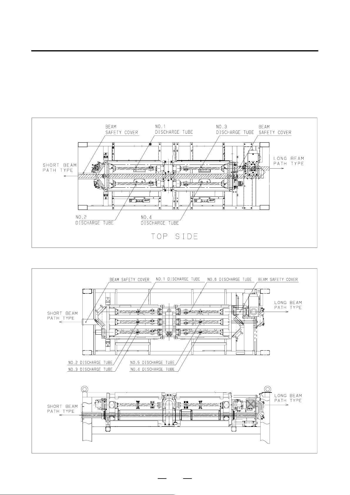
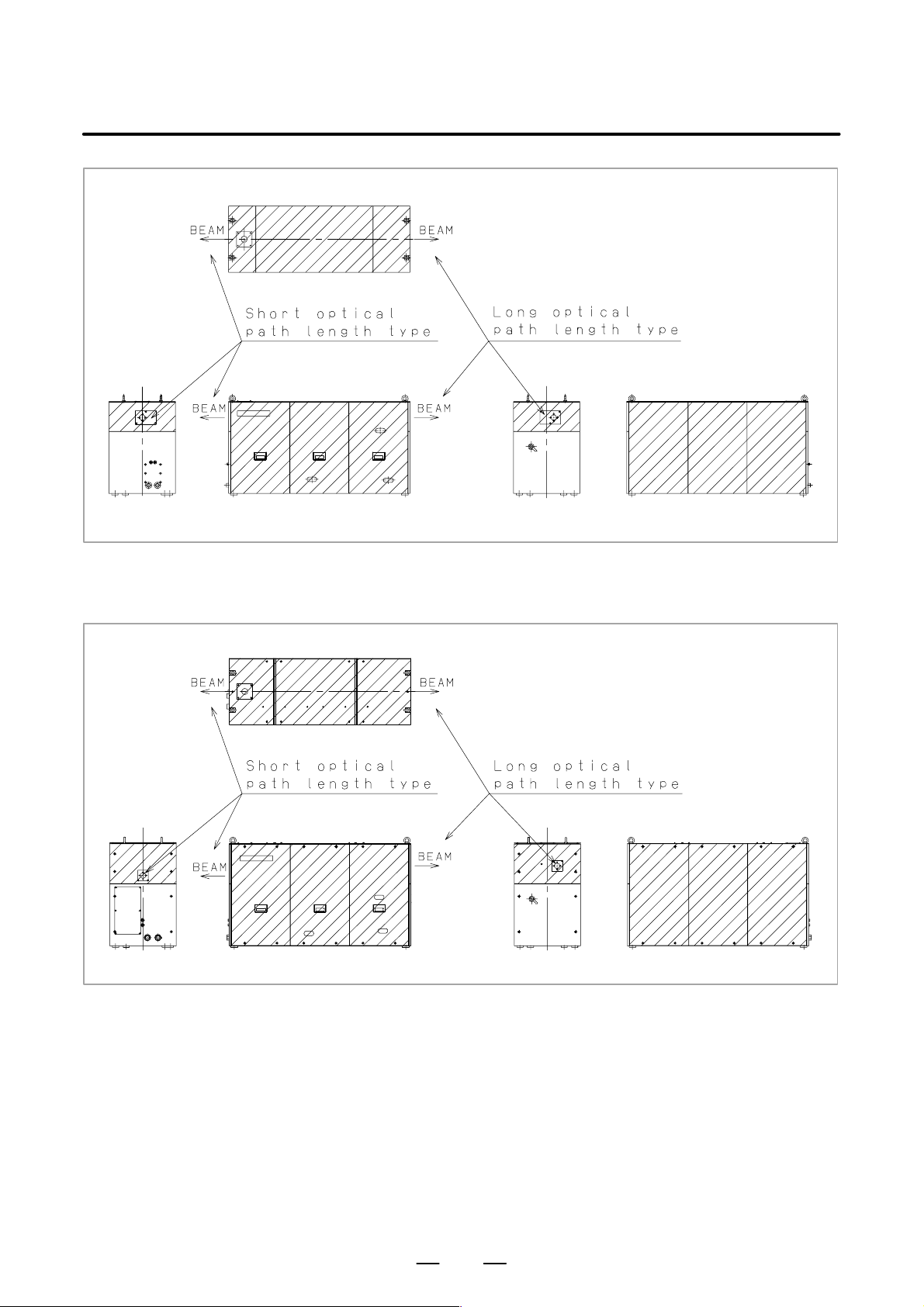
3) Position of laser beam emission
Fig. 2.1 (a) is the position of laser beam delivery in C1500B,
C2000B, C2000C.
Fig. 2.1 (b) is the position of laser beam delivery in C3000C,
C3000D.
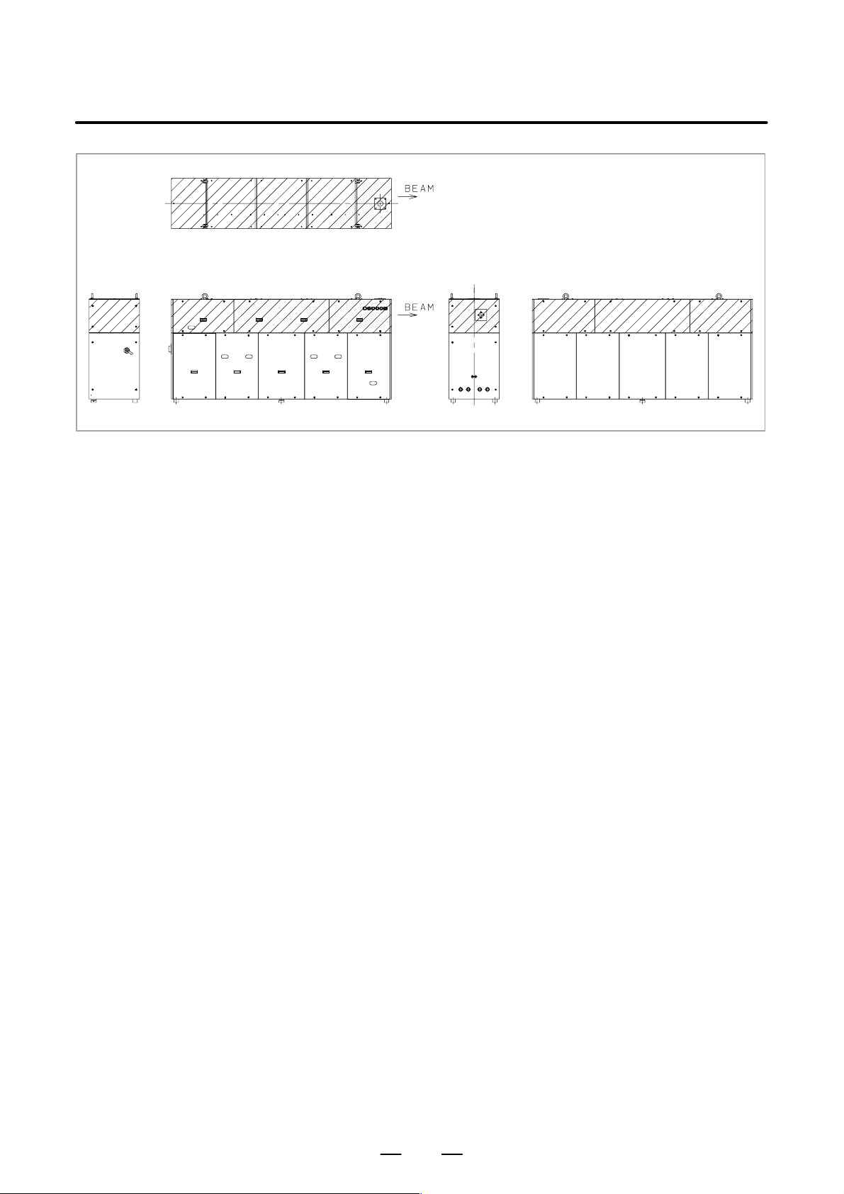
Fig. 2.1 (c) is the position of laser beam delivery in C4000A.
Fig. 2.1 (d) is the position of laser beam delivery in C6000B.
Fig. 2.1 (e) is the position of panel that laser beam exposure is
occurred without panel in C1500B, C2000B, C2000C,
C3000C, C3000D, when your maintenance.
2
6
B–70114EN/04
2. SAFETY
Fig. 2.1 (f) is the position of panel that laser beam exposure is
occurred without panel in C4000A, when your
maintenance.
Fig. 2.1 (g) is the position of panel that laser beam exposure is
occurred without panel in C6000B, when your
maintenance.
Fig. 2.1 (a) The position of laser beam delivery (C1500B, C2000B, C2000C)
Fig. 2.1 (b) The position of laser beam delivery (C3000C, C3000D)
7

2. SAFETY
B–70114EN/04
Fig. 2.1 (c) The position of laser beam delivery (C4000A)
Fig. 2.1 (d) The position of laser beam delivery (C6000B)
8
B–70114EN/04
2. SAFETY
Fig. 2.1 (e) Laser beam exposure position without panel as operating
(C1500B, C2000B, C2000C, C3000C, C3000D)
Fig. 2.1 (f) Laser beam exposure position without panel as operating (C4000A)
9
2. SAFETY
B–70114EN/04
Fig. 2.1 (g) Laser beam exposure position without panel as operating (C6000B)
10

B–70114EN/04
2. SAFETY
2.2
HIGH VOLTAGE
1) Potential hazards
There is RF voltage of 3 to 4kV
in the cabinet of the laser oscillator .
o–p
There is 200 VAC power in the relay panel, be careful not to touch the
high voltage.
2) Safety recommendations
When it checks the oscillator and exchange the unit, intercept a main
breaker of the oscillator and the power supply. Lock the breaker to
prevent misconnection and display the sign while working.
Install safety cover after unit replacement or cable connection. Unless
safety cover is installed, never perform operation.
Follow standard industrial safety practices for working with high
voltage.
EXAMPLES
D Do not work on the laser oscillator if you are tired or have taken
medicine.
D Use the buddy system.
D Do not wear anything metal, like a ring, bracelet, watch, belt
buckle, earrings, or keys.
D They might contact high voltage.
D Never stand on a wet surface.
D Do not touch electrical components in the cabinets with both hands
at once. Keep one hand in a pocket.
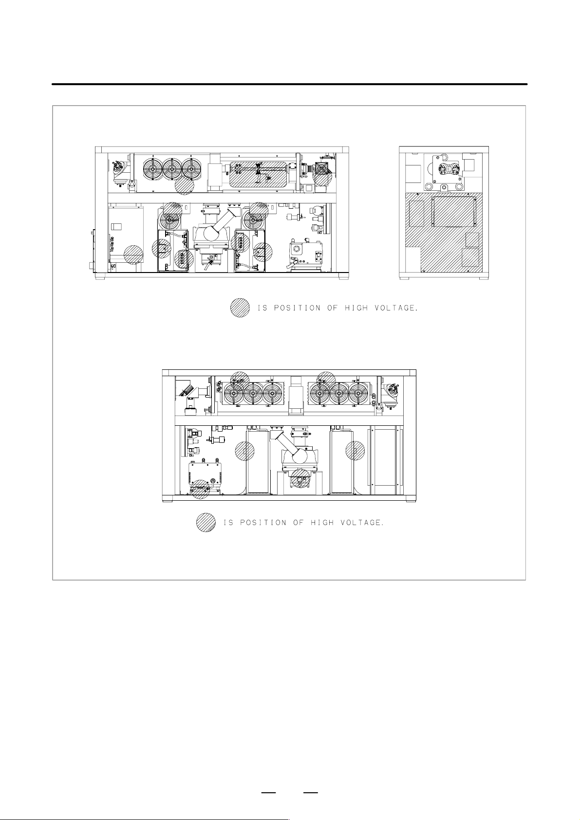
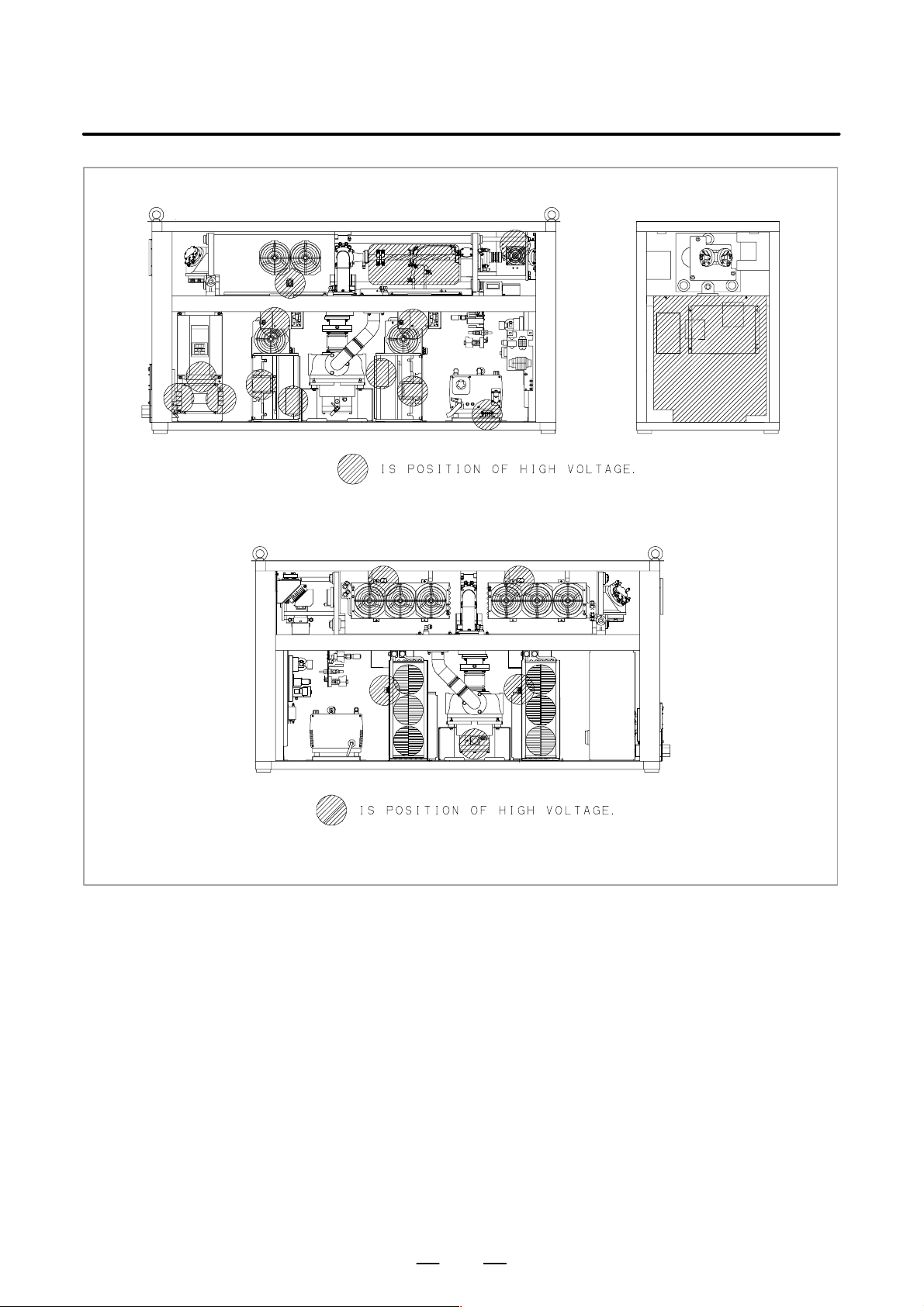
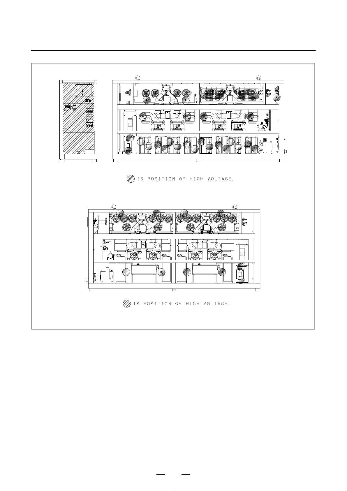
3) Position of high voltage
Fig. 2.2 (a) is the position of high voltage in C1500B (Front side,
Back side).
Fig. 2.2 (b) is the position of high voltage in C2000B (Front side,
Back side).
Fig. 2.2 (c) is the position of high voltage in C2000C (Front side,
Back side).
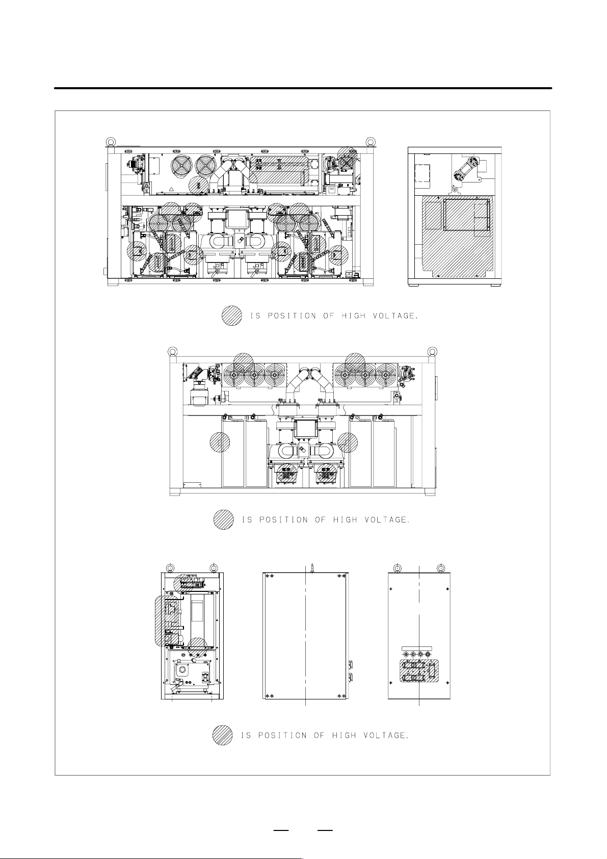
Fig. 2.2 (d) is the position of high voltage in C3000C (Front side,
Back side, AUX).
Fig. 2.2 (e) is the position of high voltage in C3000D (Front side,
Back side).
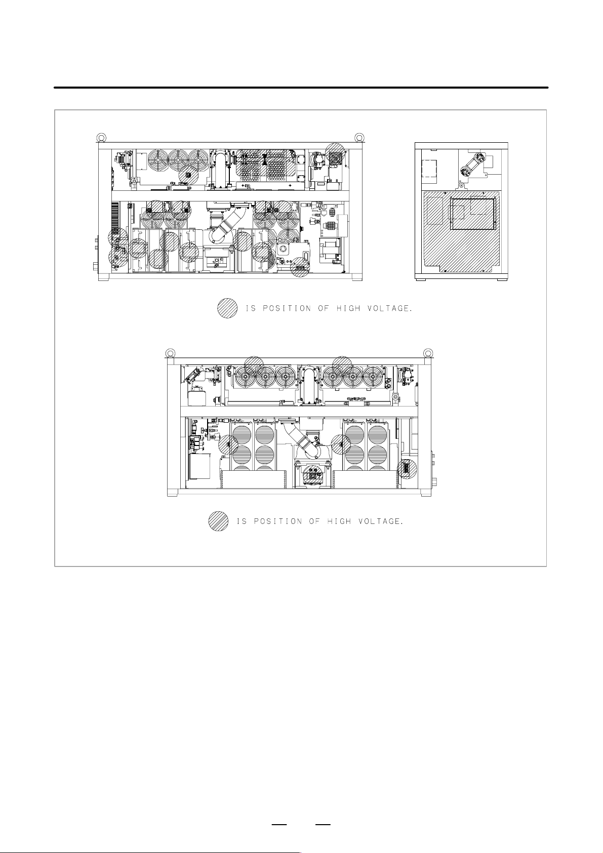
Fig. 2.2 (f) is the position of high voltage in C4000A (Front side,
Back side).
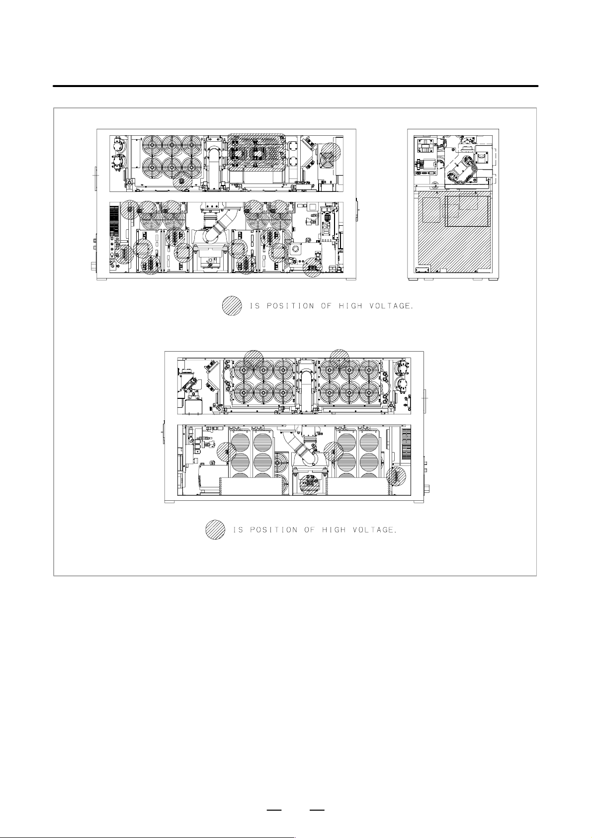
Fig. 2.2 (g) is the position of high voltage in C6000B (Front side,
Back side).
11
2. SAFETY
B–70114EN/04
Front side
Back side
Fig. 2.2 (a) The position of high voltage in C1500B (Front side, Back side)
12

B–70114EN/04
2. SAFETY
Front side
Back side
Fig. 2.2 (b) The position of high voltage in C2000B (Front side, Back side)
13
2. SAFETY
B–70114EN/04
Front side
Back side
Fig. 2.2 (c) The position of high voltage in C2000C (Front side, Back side)
14
B–70114EN/04
2. SAFETY
Front side
Back side
Auxiliary unit
Fig. 2.2 (d) The position of high voltage in C3000C (Front, Back, AUX)
15
2. SAFETY
B–70114EN/04
Front side
Back side
Fig. 2.2 (e) The position of high voltage in C3000D (Front side, Back side)
16
B–70114EN/04
2. SAFETY
Front side
Back side
Fig. 2.2 (f) The position of high voltage in C4000A (Front side, Back side)
17
2. SAFETY
B–70114EN/04
Front side
Back side
Fig. 2.2 (g) The position of high voltage in C6000B (Front side, Back side)
18

B–70114EN/04
2. SAFETY
2.3
SAFETY ENCLOSURE (AT YOUR WORK STATION)
2.4
FIRE
1) Potential hazards
beam is delivery from oscillator. Direct or scattered beam is
CO
2
exposed.
2) Safety recommendations
Mount the safety enclosure made of acrylic resin which can absorb the
laser beam around the working environment.
Mount the interlock switch on the safety enclosure door which
extinguishes the laser beam output when the door is open. Never
perform operation without safety cover of laser machine.
1) Potential hazards
When you work with the laser oscillator or machine, hot fragments or
slag can scatter from your workpiece. The CO
of it could ignite flammable material.
2) Safety recommendations
The direct or scattered laser beam can ignite flammable materials such
as paper, cloth, and wood. Provide a beam absorber behind the
workpiece and around it during maintenance. The absorber can be
anodized aluminum, graphite or brick.
Put a shield between yourself and the workpiece when the CO
is on. Even diffuse reflections can harm eyes and skin and may ignite
flammable material.
beam or a reflection
2
beam
2
2.5
TOXIC FUME
1) Potential hazards
Some materials such as certain plastics can emit toxic fume when they
burn under the laser beam.
2) Safety recommendations
Install the exhaust system to remove toxic fume from the work
environment.
Consult the manufacturer of the material you are processing to learn
if it creates any fumes when heated or burned.
19

2. SAFETY
B–70114EN/04
2.6
HIGH TEMPERATURE
1) Potential hazards
When you touch a part of high temperature, your skin burn.
2) Safety recommendations
The pipes of the gas circular system are very a high temperature. Do
not touch pipes, heat exchanger and turbo blower because it does not
do the burn. It is hot immediately after having stopped driving. After
getting cold enough in case of removing, dismount it.
3) Position of high temperature
Fig. 2.6 (a) is the position of high temperature in C1500B (Front side,
Back side).
Fig. 2.6 (b) is the position of high temperature in C2000B (Front side,
Back side).
Fig. 2.6 (c) is the position of high temperature in C2000C (Front side,
Back side).
Fig. 2.6 (d) is the position of high temperature in C3000C (Front side,
Back side, Aux).
Fig. 2.6 (e) is the position of high temperature in C3000D (Front side,
Back side).
Fig. 2.6 (f) is the position of high temperature in C4000A (Front side,
Back side).
Fig. 2.6 (g) is the position of high temperature in C6000B (Front side,
Back side).
20

B–70114EN/04
2. SAFETY
Front side
Back side
Fig. 2.6 (a) The position of high temperature in C1500B (Front side, Back side)
21

2. SAFETY
B–70114EN/04
Front side
Back side
Fig. 2.6 (b) The position of high temperature in C2000B (Front side, Back side)
22

B–70114EN/04
2. SAFETY
Front side
Back side
Fig. 2.6 (c) The position of high temperature in C2000C (Front side, Back side)
23

2. SAFETY
B–70114EN/04
Front side
Back side
Auxiliary unit
Fig. 2.6 (d) The position of high temperature in C3000C (Front , Back, Aux)
24

B–70114EN/04
2. SAFETY
Front side
Back side
Fig. 2.6 (e) The position of high temperature in C3000D (Front side, Back side)
25

2. SAFETY
B–70114EN/04
Front side
Back side
Fig. 2.6 (f) The position of high temperature in C4000A (Front side, Back side)
26

B–70114EN/04
2. SAFETY
Front side
Back side
Fig. 2.6 (g) The position of high temperature in C6000B (Front side, Back side)
27

2. SAFETY
B–70114EN/04
2.7
W ARNING LABELS
Fig. 2.7 (a)–(g) show the location of the warning labels indicating the high
voltage and laser beam path.
Fig. 2.7 (a) is the location of the warning sticker at front side. (C1500B,
C2000B, C2000C, C3000C, C3000D)
Fig. 2.7 (b) is the location of the warning sticker at back side. (C1500B,
C2000B, C2000C, C3000C, C3000D)
Fig. 2.7 (c) is the location of the warning sticker (Auxiliary unit of
C3000C)
Fig. 2.7 (d) is the location of the warning sticker at front side. (C4000A)
Fig. 2.7 (e) is the location of the warning sticker at back side. (C4000A)
Fig. 2.7 (f) is the location of the warning sticker at front side. (C6000B)
Fig. 2.7 (g) is the location of the warning sticker at back side. (C6000B)
Fig. 2.7 (a) The location of warning sticker at front side (C1500B, C2000B, C2000C, C3000C, C3000D)
28

B–70114EN/04
2. SAFETY
Fig. 2.7 (b) The location of warning sticker at back side (C1500B, C2000B, C2000C, C3000C, C3000D)
Fig. 2.7 (c) The location of the warning sticker (Auxiliary unit of C3000C)
29

2. SAFETY
B–70114EN/04
Fig. 2.7 (d) The location of warning sticker at front side. (C4000A)
Fig. 2.7 (e) The location of warning sticker at back side. (C4000A)
30

B–70114EN/04
2. SAFETY
Fig. 2.7 (f) The location of warning sticker at front side. (C6000B)
Fig. 2.7 (g) The location of the warning sticker at back side. (C6000B)
31

2. SAFETY
D Detail of warning sticker
B–70114EN/04
Warning logotype
32
7000W

B–70114EN/04
2. SAFETY
Warning logotype
Label for defeasible non–interlocked protective housing
Label for defeasible non–interlocked protective housing
33

2. SAFETY
Caution label for lifting
B–70114EN/04
Aperture label
Label of non–interlocked protective panel
34

B–70114EN/04
Identification label
2. SAFETY
80
110
110
150
Address label
High voltage warning label
150
190
300
35

2. SAFETY
B–70114EN/04
Supply voltage label
Label of over–current protective
36

B–70114EN/04
2. SAFETY
Label of motor and transformer (C1500B,C2000B,C2000C)
Label of motor and transformer (C3000C)
37

2. SAFETY
B–70114EN/04
Label of motor and transformer (C3000D)
Label of motor and transformer (C4000A)
38

B–70114EN/04
2. SAFETY
Label of motor and transformer (C6000B)
Label of warning light
Maintenance label
39

2. SAFETY
B–70114EN/04
Certification label
Short–circuit interrupting capacity of main breaker
Caution label for lifting
40

B–70114EN/04
2. SAFETY
2.8
KEY CONTROL
2.9
SHUTTER LOCK
All the laser products have to comply with the various kinds of laser safety
regulations, which include the use of key control. For instance, FDA
PART 1040 PERFORMANCE STANDARDS FOR
LIGHT–EMITTING PRODUCTS, Sec 1040. 10 (f), (4) states: “Each
laser system classified as a Class IIIb or IV laser product shall incorporate
a key–actuated master control. The key shall be removable and the laser
shall not be operable when the key is removed” and EN60825–1:1994, 4.5
Key control state “Any laser system belonging to one of the following
classes shall incorporate a key operation master control: Class 4 and Class
3B, except for Class 3B with not more than five times the AEL of Class
2 in the wavelength range from 400 nm to 700 nm. The key shall be
removable and the laser radiation shall not be accessible when the key is
removed.”
Because the laser package products offered by FANUC cannot produce
the laser beam as they are in the state of shipment, the system integrator
who incorporates FANUC products into the system, which generates the
laser beam, is obliged to incorporate the master key as defined by the
relevant regulation.
The shutter lock is prepared because it dose not put out the laser beam by
mistake. If you do not put out the beam, lock the shutter.
Use the mechanical switch at shutter lock switch, not electrical
component (Relay)or switching circuit (Transistor, FET).
Use the one with the compulsion dissociation mechanism for the switch
used for the shutter lock circuit and the switch for welding prevention.
To designer of laser processing machine
1. Use a mechanical switch for the switch used to lock the
shutter. Do not use an electric switch (For instance,
transistor circuit, etc.). Moreover, use the one with the
contact dissociation mechanism to prevent welding for a
mechanical switch.
2. Put it in the series of the contact of the emergency stop
button in the shutter lock circuit. When the emergency stop
switch is pushed, it is necessary to intercept the power
supply to the shutter.
41

2. SAFETY
B–70114EN/04
2.10
EMERGENCY STOP BUTTON
2.11
W ARNING LIGHT (OPTIONAL)
Press the emergency stop button when it is dangerous and breaks down.
The oscillator is stopped discharging, gas pressure control and stand by
purge state.
Use the one with the compulsion dissociation mechanism for the relay
used for the emer gency stop circuit and the switch for welding prevention.
FANUC LASER C series are equipped with the warning light optionally.
The light is flashed during discharging and ready of laser beam emission.
Be careful of laser beam and high voltage.
To designer of laser processing machine
In EN60825–1, it needs the design with the fail safe or
redundant for warning equipment. The redundant warning
light is needed near the work–point of processing machine.
The warning light is prepared for the oscillator. Select this as
a warning light more than the second for the fail safe.
42

B–70114EN/04
2. SAFETY
2.12
INAPPOSITE USE OF LASER OSCILLA T OR
Inapposite use and the result are described in each explanation place.
Inapposite major use are described in the following.
(1)The gas with different composition and purity from the specification
is connected with the oscillator.
The oscillator does not work normally and do the protection
movement. In the worst case, the oscillator breaks down.
(2)The gas piping with different material and structure from the
specification is used.
A leakage of the laser gas and a defective composition are occurred.
In the worst case, the oscillator breaks down.
(3)The water piping of the material, which corrodes to water, is used.
Water is blocked by the generation of rust. If cooling water does not
flow in a regulated amount, the oscillator will not work normally.
(4)Cooling water is not regularly exchanged.
W ater is blocked by the generation of rust. Moreover , it is easy for the
water fittings in the oscillator to corrode. In the worst case, the fittings
are damaged and the water leak happens.
(5)The oil of turbo blower and the exhaust pump is not regularly
exchanged.
Turbo blower is damaged and the oscillator does not work. The
exhaust pump is damaged similarly.
(6)The filter of the exhaust pump is not regularly exchanged.
The exhaust ability of the exhaust pump decreases. Moreover, white
smoke comes out from the pump exit and the oil leak happens. In the
worst case, the oscillator does not work.
(7)You will touch an unrelated place when usually maintaining.
In the oscillator there are adjustment place. The adjustment place is the
best value when shipping. When the adjustment shifts, the oscillator
will not work normally. It is necessary to adjust it by service man that
was trained.
(8)You open the panel immediately after the oscillator was stopped and
oil is exchanged.
(9)There is a place of the high temperature immediately after the
oscillator stopped. When you touches there, you will do the burn. After
getting cold of the oscillator, open the panel. Refer to safety in Chapter
2 for the place of the high temperature.
43

3. INSTALLATION
INSTALLATION
3
B–70114EN/04
44

B–70114EN/04
3.1
CONDITION
3. INSTALLATION
3.1.1
Environmental Conditions
3.1.2
Power Source
(1)Ambient temperature
+5 to 30°C
(2)Temperature drift
Max 1.1°C/min
(3)Humidity
<75% (relative)
(4)Vibration
Acceleration <0.05G
Amplitude <5µm
(5)Atmosphere
Free from dust and volatile vapor
(1)Input power and maximum current
Model Power Maximum current
C1500B 23 KVA 80 A
C2000B, C2000C 33 KVA 1 10 A
C3000C, C3000D 44 KVA 150 A
C4000A 55 KVA 190 A
3.1.3
Laser Gas
C6000B 90 KVA 300 A
(2)Voltage
200VAC+10%, –15%, 50/60Hz"1Hz, 3f
or 220VAC+10%, –15%, 60Hz"1Hz, 3f
(3)Earth–ground
S Ground (<10 ohm)
S Protective earth (PE)
For the laser gas, the following specifications are required.
(1)Composition and its accuracy
:5"0.25% Purity >99.99%
CO
2
He: 40"2.00% >99.99%
;55"2.75% (Balance) >99.99%
N
2
(2)Water vapor (H
(3)Hydrocarbon (CmHn) <1ppm
O) <5ppm
2
45

3. INSTALLATION
B–70114EN/04
3.1.4
Cooling Water
(1)Cooling water specification
The quality of cooling water is specified in the table below . If tap water
is used, it should be treated in an ion exchanger.
Refrigerator/air–conditioner cooling water quality standard
(JRA–9001–1980)
pH (25°C) 6.0 to 8.0
Conductivity (25°C)(m s/cm) 200 or less
Chlorine ion Cl* (ppm) 20 or less
*
Standard item
Reference item
Sulfate ion SO
M alkalinity CaCO3 (ppm) 50 or less
Total hardness CaCO3 (ppm) 50 or less
Iron Fe (ppm) 0.3 or less
Sulfur ion S
Ammonia ion NH
Ionic silica SiO2 (ppm) 30 or less
2
(ppm) 50 or less
4
*
2
(ppm) Not to be detected
+
(ppm) 0.2 or less
4
(2)Anticorrosive
T o avoid cooling water trouble and minimize the frequency of cooling
water exchange, the following anticorrosive should be added to the
cooling water. Consult the chiller manufacturer for use of the
anticorrosive.
Product name: CONTLIME K–6000
Manufacturer: MITSUBISHI GAS CHEMICAL. ISC
Use: Refer to the description indicated on the product.
Replace the cooling water every year , even if an anticorrosive has been
added to it.
(3)Cleaning agent
The following cleaning agent should be used. Consult the chiller
manufacturer for use of the cleaning agent.
Product name: DESLIME
Manufacturer: MITSUBISHI GAS CHEMICAL ISC
Use: Refer to the description indicated on the product.
(4)Antifreezing solution
If the chiller is used in a cold district, it should be provided with an
antifreezing function. When it is extremely cold, the chiller should be
kept running. If it is necessary to use an antifreezing solution for lack
of an alternative, the following antifreezing solution should be used.
Its concentration should be 30% (usually) or 40% (in an extremely
cold district). Use of an antifreezing solution should be restricted
within four months in winter. Do not use antifreezing solution
together with an anticorrosive. The following antifreezing solution is
already added with an anticorrosive.
Product name: AURORA BRINE
Manufacturer: TOKYO FINE CHEMICAL Co.
Use: Refer to the description indicated on the product.
46

B–70114EN/04
3. INSTALLATION
Caution
In winter or in a cold district, when the oscillator is at a rest and
the ambient temperature gets to or below the freezing point,
the cooling water in the oscillator freezes, possibly breaking
the water pipe or damaging the chilling unit. When the
oscillator is not in use, drain cooling water from it. To drain
water, keep blowing compressed air at 5 kgf/cm2 or less into
the oscillator through the cooling water inlet for 15 minutes.
47

3. INSTALLATION
3.2
TRANSPORTATION
B–70114EN/04
3.2.1
Lifting Laser Oscillator
In lifting the FANUC LASER C series, be sure to use the four eyebolts
screwed into the top surface of the cabinet as shown in the figure. Never
lift using only the two bolts. The weight is shown following tables. The
permissible impact value of the oscillator is 2G. When the impact which
exceeds the permissible impact value is given, the resonator will warp and
the shape of the beam mode worsens.
Fig. 3.2.1 Method of lifiting
48

B–70114EN/04
3. INSTALLATION
3.2.2
Packing
1) Clamp
When shipped from FANUC, the two components of the laser listed
below are in the clamped position. Because this is for shipment only,
remove the clamp during the installation. Be sure to use the clamp,
when the machine is shipped again. (1) Optical resonator (2)
Mechanical shutter.
Fig.3.2.2(a)–(d) are clamp layout.
Fig. 3.2.2 (a) Clamp layout (C1500B, C2000B, C2000C, C3000C, C3000D)
49

3. INSTALLATION
B–70114EN/04
Fig. 3.2.2 (b) Clamp layout (C4000A)
50

B–70114EN/04
3. INSTALLATION
Fig. 3.2.2 (c) Clamp layout (C6000B)
51

3. INSTALLATION
B–70114EN/04
Fig. 3.2.2 (d) Clamp layout (C6000B)
CAUTION
If the machine is not clamped during transportation, the
optical resonator may cause distortion or may be damaged.
52

B–70114EN/04
3. INSTALLATION
2) Water
Be sure to drain water in the oscillator at shipment.
Refer to the maintenance manual for draining.
CAUTION
If water remains in the oscillator, internal water pipes may
be damaged in cold climates.
3.2.3
Environmental Condition
3.3
STORAGE
(1)Temperature
–20 to 50°C
CAUTION
Must be completed to drain in the oscillator. If water remain
in the oscillator, water freeze during the transportation at
cold district. Therefore oscillator is damaged.
(2)Humidity <75% (relative)
(3)Vibration
Acceleration < 0.05G
Amplitude < 5µm
(4)Atmosphere
Free from the dust and the volatile vapor
The various kinds of clamps should be used only during the
transportation. Especially the clamps used for resonator should be
loosened during the storage. Storing the resonator as fixed with the
clamps for a long time will cause its distortion. The clamps are provided
for cavity, shutter unit.
Do not keep the oscillator in the place of the high temperature humidity.
Otherwise, it generates rust in the resonator.
3.3.1
Environmental Condition
(1)Temperature
–20 to 50°C
CAUTION
Must be completed to drain in the oscillator. If water remain
in the oscillator, water freeze during the transportation at
cold district. Therefore oscillator is damaged.
(2)Humidity < 75% (relative)
(3)Vibration
Acceleration <0.05G
Amplitude <5µm
(4)Atmosphere
Free from the dust and the volatile vapor
(5)Location
Plain, no slope
53

3. INSTALLATION
B–70114EN/04
3.4
BASE OF OSCILLATOR
In F ANUC LASER C series, the two type of that is the four taps and hole
are prepared in the base as shown in the figure for fixing the laser cabinet
against the machine base.
Fig. 3.4 (a) Mounting (A)
54
Fig. 3.4 (b) Mounting (B)

B–70114EN/04
3. INSTALLATION
Fig. 3.4 (c) Cabinet base (C1500B, C2000B, C2000C, C3000C, C3000D, C4000A)
Fig. 3.4 (d) Cabinet base (C6000B)
55

3. INSTALLATION
B–70114EN/04
3.5
MAINTENANCE AREA
The maintenance areas of FANUC LASER C series are shown in the
figures below. The customer is requested to prepare adequate space
around the laser even for the sides, which are not requested in the figures.
Fig. 3.5 (a) Maintenace area (C1500B: Short type)
56

B–70114EN/04
3. INSTALLATION
Fig. 3.5 (b) Maintenace area (C1500B: Long type)
57

3. INSTALLATION
B–70114EN/04
Fig. 3.5 (c) Maintenace area (C2000B, C3000C, C3000D: Short type)
58

B–70114EN/04
3. INSTALLATION
Fig. 3.5 (d) Maintenace area (C2000B, C3000C, C3000D: Long type)
59

3. INSTALLATION
B–70114EN/04
Fig. 3.5 (e) Maintenance area (Auxiliary unit)
60

B–70114EN/04
3. INSTALLATION
Fig. 3.5 (f) Maintenace area (C2000C: Short type)
61

3. INSTALLATION
B–70114EN/04
Fig. 3.5 (g) Maintenace area (C2000C: Long type)
62

B–70114EN/04
3. INSTALLATION
Fig. 3.5 (h) Maintenace area (C4000A: Short type)
63

3. INSTALLATION
B–70114EN/04
Fig. 3.5 (i) Maintenace area (C4000A: Long type)
64

B–70114EN/04
3. INSTALLATION
Fig. 3.5 (j) Maintenace area (C6000B)
65

3. INSTALLATION
3.6
WATER CONNECTION
B–70114EN/04
3.6.1
Chiller
Make the cooling water re–circulate in the closed loop using a chiller unit.
The cooling requirements of the chiller are as below.
(1)Chiller capacity
Type Capacity
C1500B >15.7kW
C2000B, C2000C >22kW
C3000C, C3000D >33.7kW
C4000A >44.2kW
C6000B >67.5kW
(2)Temperature control range 20 to 30°C
(3)Temperature accuracy "1°C
(4)Water pressure 5.0 bar or less
(5)Heat exhaust Water cooling or air cooling
(6)Attachment
f Water filter
f Water valve
f Flow switch
f Interface to externally switch of chiller
f Contact interface to send signal of normal operation of
chiller(CLRDY).
3.6.2
Cooling Water Temperature
Note
Output the signal of “contact on” when everything is normal
with cooling water flow rate, temperature, water level,
overheat switch of chiller, high and low pressure switch,
over–current relay, etc.
Throughout the year, set the chiller water temperature to 27°C in general
regions and 30°C in humid regions.
66

B–70114EN/04
3. INSTALLATION
3.6.3
Cooling Water Flow Rate
3.6.4
Plumbing
The flow rate should be chosen so that the temperature difference between
the inlet and outlet of the chiller becomes less than 3°C. The customer can
refer to the following table.
Type Flow rate
C1500B 50 liter/min
C2000B, C2000C 75 liter/min
C3000C, C3000D 120 liter/min
C4000A 160 liter/min
C6000B 250 liter/min
The cooling water from chiller is temperature–regulated.
D Choose the tubing material which can withstand corrosion, which will
choke the water flow.
D Make the hose length between the laser and chiller as short as possible.
Along hose makes the pressure 1oss high and becomes a burden to the
chiller pump.
D Place a strainer at the water inlet of laser. It will prevent the f1owing
in of the dust into the laser.
D Place flow meters both at the inlet and outlet of the laser. Daily
checking of the water f1ow contributes to the prevention of abrupt stop
of laser operation.
The water fittings of the inlet and outlet of lasers are shown below.
67

3. INSTALLATION
B–70114EN/04
Fig. 3.6.4 (a) W ater connection and gas connection (C1500B, C2000B)
68

B–70114EN/04
3. INSTALLATION
Fig. 3.6.4 (b) W ater connection and gas connection (C2000C)
69

3. INSTALLATION
B–70114EN/04
Fig. 3.6.4 (c) W ater connection and gas connection (C3000C)
70

B–70114EN/04
3. INSTALLATION
Fig. 3.6.4 (d) W ater connection and gas connection (C3000C)
71

3. INSTALLATION
B–70114EN/04
Fig. 3.6.4 (e) W ater connection and gas connection (C3000D)
72

B–70114EN/04
3. INSTALLATION
Fig. 3.6.4 (f) Water connection and gas connection (C4000A)
73

3. INSTALLATION
B–70114EN/04
Fig. 3.6.4 (g) W ater connection and gas connection (C6000B)
74

B–70114EN/04
3.7
LASER GAS
3. INSTALLATION
3.7.1
Gas Bottle
3.7.2
Laser Gas Tubing
3.7.3
Gas Pipe
Use the gas bottle of the volume of 7m3. Store the necessary number of
bottles according to the operation of the laser.
Drawing of last chapter 1 shown laser gas connection of inlet and outlet.
Inlet and outlet fittings on laser are female PT 3/8”.
(1)Gas inlet of oscillator
D Use the tube designated. (FANUC recommends the use of AS1
tube manufactured by Jyunkosha.)
Do not use a tube possessing high permeability to He. (In the worst
case, the laser will be damaged by improper gas composition.)
D Use the gas of the correct composition.
(2)Gas outlet of oscillator
The oil mist and the dissociated gas come out from the exit of the gas.
Tie the piping of 3/8 inches or more to the gas exit and put it out to
outdoor. It will load the exhaust pump when thin piping or extremely
1ong and the exhaust ability decreases occasionally.
Observe the following cautions for piping between the laser gas cylinder
and laser oscillator.
D Use nylon tube having an inside diameter of 8 mm or larger (Junlon
AS1 manufactured by Junkousha, or equivalent). Do not use a rubber
or urethane tube.
D Use a swage–lock vacuum joint (Fujikin’s product or equivalent). Do
not use a one–touch coupler, quick coupler, or hose–band joint.
D Minimize the length of tubing. It should be kept within 5 m. Never
exceed 15 m. For a length of 15 m or greater, use stainless pipe.
D If it is necessary to use metal pipe for lack of an alternative, use
stainless bright annealed pipe. Minimize the number of joints used.
Connect pipes, if necessary, using a swage–lock vacuum joint or by
TIG welding. Do NOT use silver soldering or copper piping. Piping
should be installed by a vacuum piping specialist. Do not extend metal
piping over 30 m.
D Always keep the piping materials clean. Do not allow foreign matter
to get in the pipe.
D Use a pressure reducer that is free from gas leakage.
D After installing the pipe, check it for gas leakage, using a liquid leak
checker (Gyupoflex: A98L–0001–0856, detecting bubbles caused by
leaking gas) or a clamp test
1)
.
Note
1. Open the valve of the gas cylinder to pressurize the inside
of the pipe, then close the valve. Check to see if the
pressure in the pipe becomes low with time. Monitor the
primary pressure of the gas reducer for over 8 hours. If the
gas pressure becomes lower by 10% within 8 hours, gas is
likely to be leaking. Take an appropriate measure.
75

3. INSTALLATION
B–70114EN/04
3.8
LASER BEAM
3.8.1
Position and Tolerance of Laser Beam Exit
Here explanation are given for the convenience of designing machines.
The following figures and attached tables show the positions and
tolerances of beam.
Fig. 3.8.1 (a) Beam exit (C1500B, C2000B, C2000C, C3000C,
C3000D, C4000A)
Fig. 3.8.1 (b) Beam exit (C6000B)
76

B–70114EN/04
3. INSTALLATION
Fig. Position of laser beam exit
Model W1 W2 W3 H
C1500B, C2000B, C2000C
Short path length type
C1500B, C2000B, C2000C
Long path length type
C3000C, C3000D, C4000A
Short path length type
C3000C, C3000D, C4000A
Long path length type
C6000B 435"5 70 505 1375"5
3.8.2
310"5 65 375 876"5
390"5 65 455 876"5
310"5 65 375 811"5
420"5 65 485 921"5
The beam divergence for FANUC LASER C series is less than 2 mrad.
Beam Divergence
3.8.3
Tolerance of Beam Direction
The tolerance of beam direction is "0.3 degrees. The customer is
requested to prepare adjusting mechanism on the machine side to
compensate for the beam direction error.
3.8.4
Beam Guide
The laser had better be isolated mechanically from the machine for
preventing the coupling between them. The vibration might enter the
opponent from each side. It is, however, absolutely necessary to provide
the beam guide between them so that the operator is protected from the
exposure to the laser beam all the time. The structure of the beam guide
must permit the mechanical de–coupling required as shown in the figure.
77

3. INSTALLATION
B–70114EN/04
3.9
ELECTRIC CONNECTION
The following cables should be connected to the laser. Refer to the
Connecting Manual of the controller (CNC).
Cable connection point and clamp of cable refer to Fig. 3.9 (a) to (h). All
cable must be used the cable inlet.
Fig. 3.9 (a) Cable connection (C1500B)
Fig. 3.9 (b) Cable connection (C2000B)
78

B–70114EN/04
3. INSTALLATION
Fig. 3.9 (c) Cable connection (C2000C)
Fig. 3.9 (d) Cable connection (C3000C)
79

3. INSTALLATION
B–70114EN/04
Fig. 3.9 (e) Cable connection (C3000C)
Fig. 3.9 (f) Cable connection (C3000D)
80

B–70114EN/04
3. INSTALLATION
Fig. 3.9 (g) Cable connection (C4000A)
Fig. 3.9 (h) Cable connection (C6000B)
81

3. INSTALLATION
B–70114EN/04
3.9.1
Power Cable (L1, L2, L3)
3.9.2
Ground Cable
3.9.3
I/O Signal Cable
Use the cable with 4 cores. (C1500B, C2000B, C2000C, C3000C,
C3000D, C4000A)
Conductor cross section must be more than 22mm
(C2000B, C2000C, C3000C, C3000D, C4000A).
Outer diameter of cable must be between f 22mm to f 32mm (C1500B),
f 28mm to f 38mm (C2000B, C2000C, C3000C, C3000D, C4000A).
Use the 4 cable (C6000B)
Conductor cross section of one cable must be more than 100 mm
The one of earth cable should be connected to the Cu plate upon which
the laser power supply units are mounted. (Earth [<10 ohm], Protective
earth). The other of earth cable is protective earth and should be connected
to the laser at left upper of input unit. This point is marked “PE”.
D For 16–L, 16–iL (one cable)
Optical fiber cable should be connected to COPIB of IF PCB.
(Connect Jumper pins SP5 and SP6 of IF to the 2–3 side.)
D For 0–L (two cables)
Metal cables should be connected to CN1 and CN2 of IF PCB.
2
(C1500B), 35mm
2
.
2
3.9.4
Other Signal Cables to the IF PCB
D For 16–L, 16i–L
1) Emergency stop signal input (ESP1, ESP2)
This terminal is shorted usually.
2) OFF prohibition signal (OFI1,OFI2) – (EOF, COM) CNC side
A contact
Closing the contact to inhibit the OFF switch operation.
Connection parallel with the OFF switch. Contact capacity
250VAC, 3A or 30 VDC, 5A.
3) Laser power unit ON/OFF signal (ON, OFF) – (EXR, EXS) CNC
side
When a door interlock is used. Connect 200VAC whose ON/OFF
is controlled by CNC Capacity 200VAC, 10mA
4) Door interlock contact signal (DIL1, DIL2)
B contact (AC200V applied to laser and CNC is shut in OPEN
state.)
When the door of the oscillator is open, the contact opens. When
the contact are open, the ON – OFF signal of 200 VAC, 3A or 30
VDC, 5A.
82

B–70114EN/04
3. INSTALLATION
Fig. 3.9.4 (a) Detail of IF PCB 16–L
Fig. 3.9.4 (b) Detail of 16i–L
83

3. INSTALLATION
B–70114EN/04
D For 0–L
1) Fuse alarm signal (FAL1, FAL2)
The warning signals contact of the thermal switch and circuit
protector. When the contact is closed, turn off either the CNC
power supply or the laser power supply ON/OFF signal. Contact
capacity 220 VAC, 6A or 24VDC, 10A.
2) OFF prohibition signal (OFS1, OFS2)
Closing the contact to inhibit the OFF switch operation. Connect
in parallel with the OFF switch. Contact capacity 250VAC, 3A or
30 VDC, 5A.
3) Laser power unit ON/OFF signal (ON, OFF)
When the door interlock is used.
Connect 200VAC whose ON/OFF is controlled by CNC
Capacity 200 VAC, 10mA
4) Door interlock contact signal (ND11, ND12)
B contact (AC200V applied to laser and CNC is shut in OPEN
state.)
Use the key switch with the compulsion dissociation mechanism
for the key switch used for welding prevention. When the door of
the oscillator is open, the contact opens. When the contact is open,
the ON–OFF signal of 200 VAC, 3A or 30 VDC, 5A.
Fig. 3.9.4 (c) Detail of IF PCB 0–L
84

B–70114EN/04
3. INSTALLATION
3.9.5
XT20 Terminal
The diagram of safety interlock circuit is shown in Fig. (a) to (g). T erminal
layout is shown in Fig. (h).
Fig. 3.9.5 (a) Safety interlock circuit (C1500B)
85

3. INSTALLATION
B–70114EN/04
Fig. 3.9.5 (b) Safety interlock circuit (C2000B)
86

B–70114EN/04
3. INSTALLATION
Fig. 3.9.5 (c) Safety interlock circuit (C2000C)
87

3. INSTALLATION
B–70114EN/04
Fig. 3.9.5 (d) Safety interlock circuit (C3000C)
88

B–70114EN/04
3. INSTALLATION
Fig. 3.9.5 (e) Safety interlock circuit (C3000D)
89
 Loading...