

Page 1

GE Fanuc Automation
Computer Numerical Control Products
Servo and Spindle Motors
Exposed to Liquids
GFK-1046E April 1999
Page 2

Warnings, Cautions, and Notes
as Used in this Publication
Warning notices are used in this publication to emphasize that hazardous voltages, currents,
temperatures, or other conditions that could cause personal injury exist in this equipment or
may be associated with its use.
In situations where inattention could cause either personal injury or damage to equipment, a
Warning notice is used.
Caution notices are used where equipment might be damaged if care is not taken.
GFL-001
Warning
Caution
Note
Notes merely call attention to information that is especially significant to understanding and
operating the equipment.
This document is based on information available at the time of its publication. While efforts
have been made to be accurate, the information contained herein does not purport to cover all
details or variations in hardware or software, nor to provide for every possible contingency in
connection with installation, operation, or maintenance. Features may be described herein
which are not present in all hardware and software systems. GE Fanuc Automation assumes
no obligation of notice to holders of this document with respect to changes subsequently made.
GE Fanuc Automation makes no representation or warranty, expressed, implied, or statutory
with respect to, and assumes no responsibility for the accuracy, completeness, sufficiency, or
usefulness of the information contained herein. No warranties of merchantability or fitness for
purpose shall apply.
©Copyright 1999 GE Fanuc Automation North America, Inc.
All Rights Reserved.
Page 3
Content of this Manual
Chapter 1. Protection Standards: Provides basic product information and how they relate
to IEC standards.
Chapter 2. User Specifications: Provides a tool that end users can use to help their
machine suppliers provide machines that meet consistent standards of protection.
Chapter 3. Application Guide: Provides a foundation for the machine tool builder by
pointing out the elements that can affect coolant entry, modes of motor failure,
and more extreme methods of keeping motors dry.
Chapter 4. Machine Runoff Checklist: This checklist can be used during machine design
and test or after installation at the user site.
Chapter 5. Preventive Maintenance: Describes the steps that can be used to identify
potential motor failures as well as basic preventive maintenance procedures.
Preface
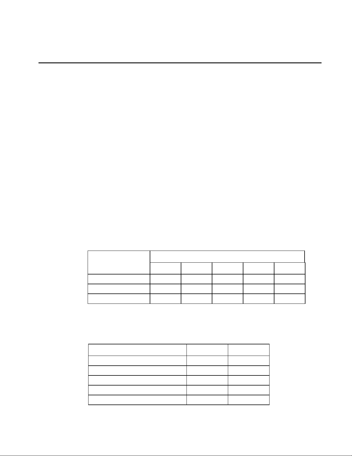
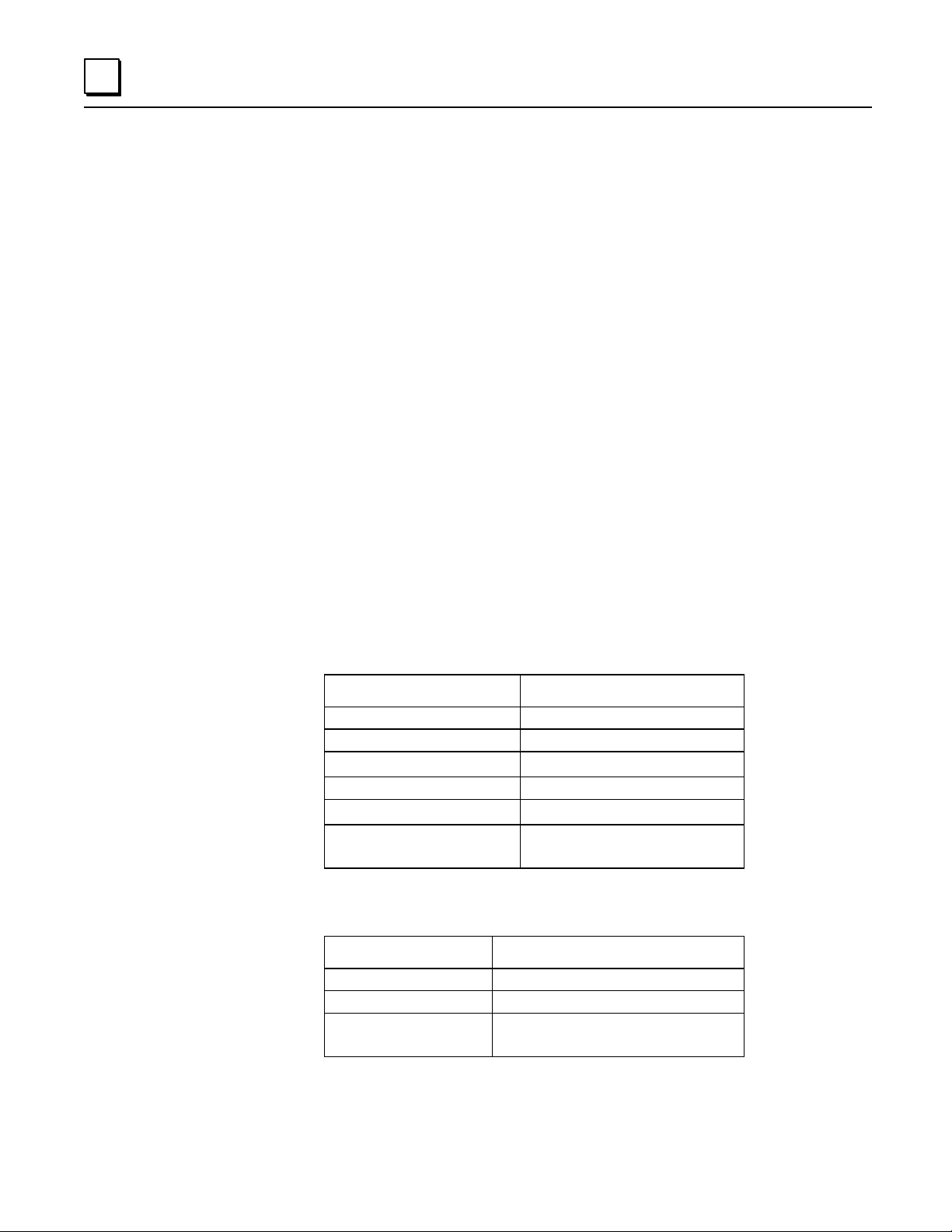
The following table identifies the chapters which will be most useful to each type of user.
Function 1 2 3 4 5
Machine Tool Builder Yes Yes Yes Yes No
End User / Specifier No Yes Yes Yes No
User Maintenance / Service No No Yes Yes Yes
Related Publications
Publication S Series αα ß Series
Servo Descriptions Manual GFZ-65002E GFZ-65142E
Servo Maintenance Manual GFZ-65005E GFZ-65165E
Spindle Descriptions Manual GFZ-65042E GFZ-65152E
Spindle Maintenance Manual GFZ-65045E GFZ-65165E
ß Series Servo Motor Descriptions Manual GFZ-65232EN
Refer to this Chapter:
GFK-1046E iii
Page 4

Contents
Chapter 1 Protection Standards............................................................................................ 1-1
Oil Seals............................................................................................................................1-1
Connectors.........................................................................................................................1-2
IEC Protection Standards...................................................................................................1-3
Chapter 2 User Specifications................................................................................................ 2-1
All Motor Applications ......................................................................................................2-1
Motors Subjected to Liquids...............................................................................................2-5
Chapter 3 Application Guide ................................................................................................. 3-1
Boot System.......................................................................................................................3-2
IEC Standards....................................................................................................................3-3
When Coolant Enters a Motor............................................................................................3-4
Drains and Pressurization...................................................................................................3-4
Fans and Derating..............................................................................................................3-4
Chapter 4 Machine Runoff Checklist.................................................................................... 4-1
Checklist............................................................................................................................4-2
Chapter 5 Preventive Maintenance....................................................................................... 5-1
Maintenance for Drives in a Normal Environment...............................................................5-2
Maintenance for Drives in a Wet Environment.................................................................... 5-3
Modification to the Motor ..................................................................................................5-4
GFK-1046E v
Page 5
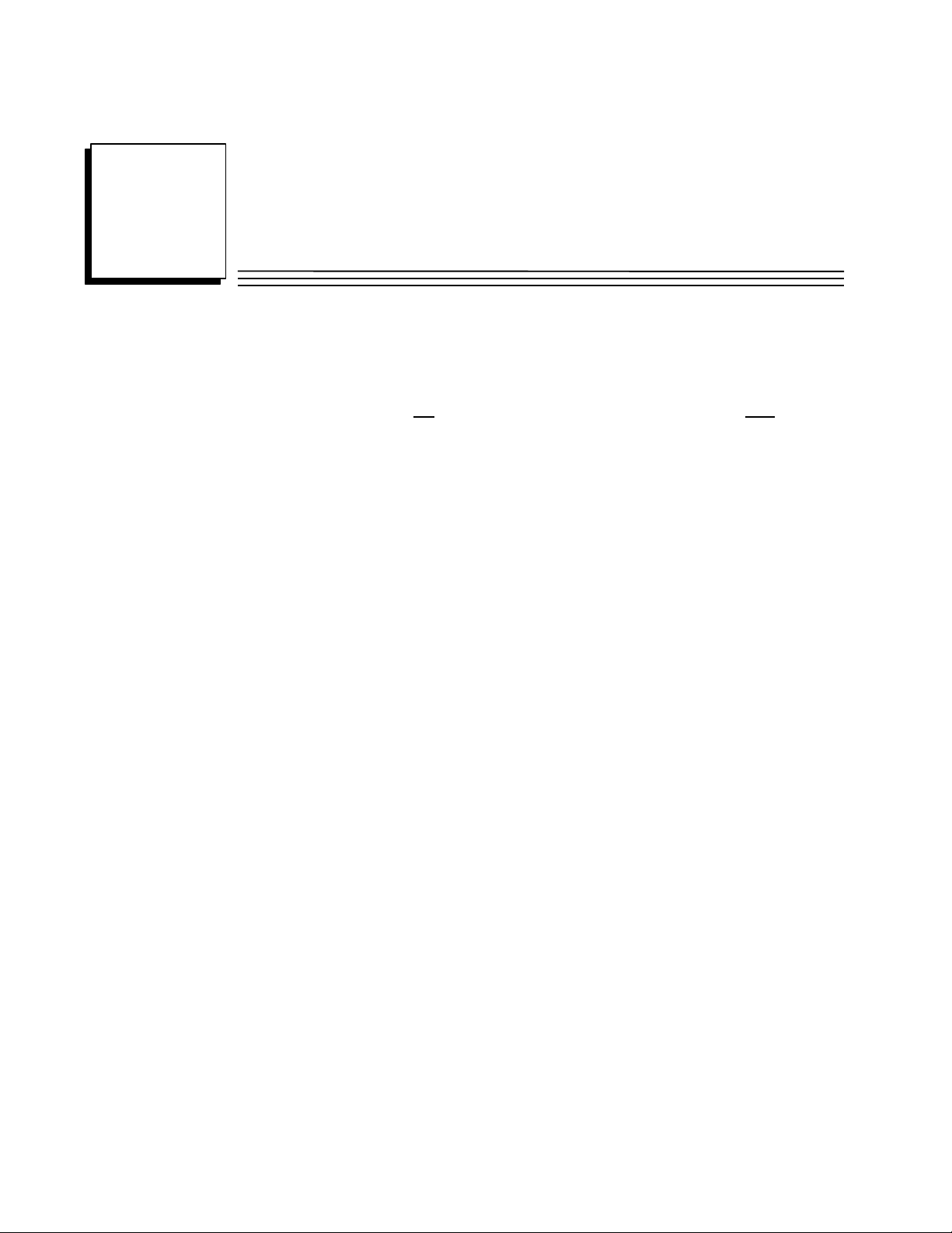
Chapter
1
Oil Seals
Protection Standards
Developing and maintaining a highly efficient and productive system involves the machine tool
builder, the drives/controls supplier, and the end user. The system design, selected components,
and manner in which the equipment is installed, used, and maintained all contribute to the uptime
of the system.
Oil seals are designed to keep oil from entering the motor through the shaft end. Oil seals do not,
however, prevent the entry of any liquids under pressure.
Caution
When liquid is present during the cooling period of a motor, lower air
pressure in the motor may result in the motor breathing in the liquids.
GFK-1046E 1 - 1
Page 6
1
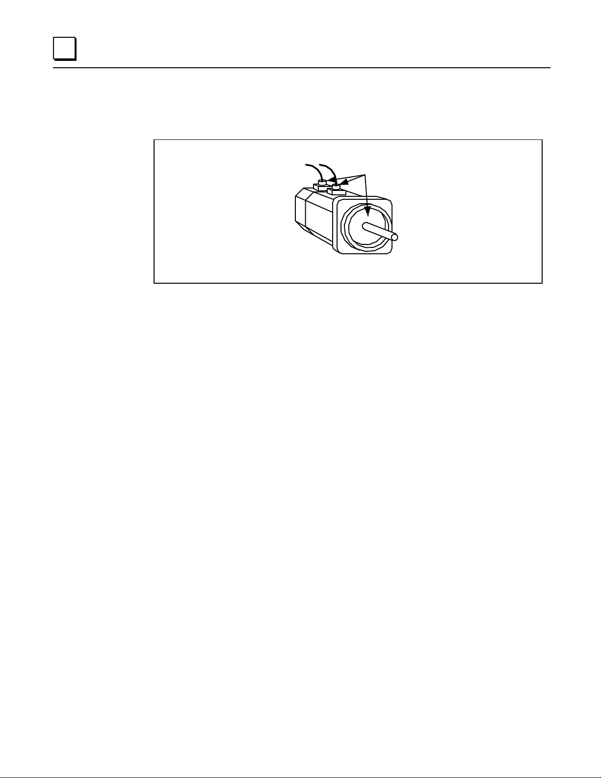
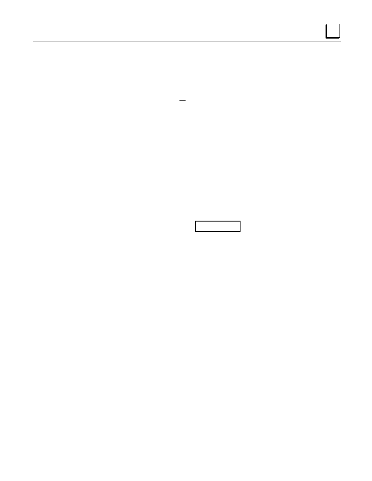
The following illustration identifies the most vulnerable areas for coolant entry.
a48031
Most Vulnerable
for Coolant Entry
Figure 1 - 1. Coolant Entry
Connectors
Note
Foot-mount style spindle motors are only supplied with shaft oil seals as an
available option.
Servo motor models 0S through 40S and α3 through α40 have the same type of cable connector
system (power, feedback, and brake). The cable connector system is designed to accept MS-type
connectors.
SP-style, α1, and α2 motors use a D-type connector system. The D-type connector system has
connectors that are as effective as MS-protected types.
1 - 2 Servo and Spindle Motors Exposed to Liquids - April 1999 GFK-1046E
Page 7
IEC Protection Standards
GE Fanuc motors are designed to meet the IEC protection standards listed in Table 1-1. These
standards are based on two characteristics, the first being protection from solid objects and the
second being protection from water.
Table 1 - 1. IEC Protection Standards
Standard * Description
IP4x Protected against solid objects greater than 1 mm thickness or diameter.
IP5x Protected against dust. "Ingress of dust is not totally prevented, but dust does not enter in sufficient
IP6x Dust tight. "No ingress of dust."
IPx2 Protected against dripping water, rate equivalent to 3-5 mm of rain per minute.
IPx4 Protected against splashing water from any direction.
IPx5 Protected from harmful damage due to water jets, according to the following test:
IPx7
(see note below)
* Each standard listed below also satisfies the requirements of the lower rated standards beneath it.
For example, IPx5 also meets the standards for IPx4, IPx3, IPx2, and IPx1. For more information, refer to CEI/IEC 34-5; 1991.
quantity to interfere with satisfactory operation of the equipment."
• Spray from all angles of 12.5 liters/minute.
• Nozzle diameter = 6.3 mm.
• Pressure = 30 kN/m2 (0.3 bar).
• Distance = 3 m.
• Duration = 3 minutes.
Protected against the effects of immersion, according to the following test:
• Surface of the water level shall be at least 150 mm above the highest point of the machine.
• Lowest point of the machine must be at least 1 meter below the surface of the water.
• Duration of the test must be at least 30 minutes.
• Water temperature must not differ from that of the machine by more than 5° C.
1
Protection from Solid Objects
Protection from Water
Note
By agreement between the manufacturer and the user, this test may be replaced
by the following procedure:
The machine should be tested with an inside air pressure of about 10 kPa (0.1
bar). The duration of the test is one minute. If no air leaks out during the test,
the test is satisfactory. Air leakage may be detected either by submersion, with
water just covering the machine, or by the application on to it of a solution of
soap in water.
GE Fanuc tests according to this alternate procedure. Using the other procedure
requires removing the end cap and checking for water in the motor. This
destroys the integrity of the seal.
GFK-1046E Chapter 1 Protection Standards 1 - 3
Page 8
1
IEC ratings provide a good indication of the expected performance of GE Fanuc motors because
they are test-based systems. However:
• To meet the standard, the shaft end and electrical connections (connector or terminal box)
must be appropriately protected by the customer.
• Because the second characteristic is based on water, the effect of various coolant materials
cannot be accurately predicted.
• Motors built to meet IP65 or IP67 go through a different manufacturing process. These
protection levels cannot be readily added in the field.
• If a motor is modified (i.e., by rotating the connector, by removing the end cap to change the
encoder, etc.), the protection rating is voided.
• Oil seals and connectors are the same in both standard motors and in those motors with
higher levels of protection.
• Compared to standard motors, IP67-rated motors have additional materials applied to mating
surfaces. Depending on the surfaces, these may include varnish, rubber-based gaskets, and
RTVs. In addition, a polyurethane-based paint is applied to the exterior painted surfaces, and
motor is tested by submersion for leak test.
To maximize the service provided by the motors, regardless of their protection
level, they should be protected from continuous wetting by coolants.
Table 1 - 2. Servo Motors
Hollow Shaft "T" Motors Not rated
5-0 Not rated
4-0S, 3-0S, 50S, 60S, 70S, α0.5
2-0SP through 30S IP55 Standard
α1 through α150, β0.5 through β6
40S and α40
Table 1 - 3. Spindle Motors
Model IEC Standard
Built-in Motors Not rated
Selected 1S through 3S IP65 Optional
All Others IP54 (excluding fan and terminal box)
Note
Model IEC Standard
Not rated
IP65 Standard (IP67 Optional)
IP55 Standard (excluding fan)
IP67 Optional (excluding fan)
IP44 (fan and terminal box included)
1 - 4 Servo and Spindle Motors Exposed to Liquids - April 1999 GFK-1046E
Page 9

Chapter
User Specifications
2
All Motor Applications
For all motor applications, please follow this procedure:
1. Test machine runoff with all the equipment guards in place and with the same coolant
nozzles and pressures designed for production.
2. Orient the motor connectors down and/or away from the predominant source of liquids.
3. Use sealing-type connectors to keep moisture out. Where MS connectors are used, they must
be type F or R.
α1 and α2 and β1 through β6 motors use D sub 15P A068-6050-K115 for feedback.
MS connectors are available, in kit form, from GE Fanuc. The kit consists of a connector,
“O” ring, bushing, clamp, and grommet. These are listed as the "environmental type" in
Table 2-1.
4. An alternate way to waterproof the connector and cable termination is to use a heat shrink
boot. Boots are used on the GE Fanuc severe duty cables listed in Tables 2-2 and 2-3. (Boots
for connectors consisting of boot, gel disk (optional), and instructions for use are listed in
Table 2-1.)
Connector kits are also available. A connector kit includes both the CE95 connector and the
boot.
5. The severe duty cables, listed in Tables 2-2 and 2-3, are high flex, polyurethane jacketed
cables with sealed connectors. The polyurethane jacket resists degrading by the coolant.
6. Physical barriers, such as deflector plates, shrouds, and splash guards, should be used to
minimize liquids falling on or hitting the motor.
7. Cables should have drip loops to prevent liquids from traveling along the cable to the motor
connector.
8. Any removable cover, door, shield, or other device, which protects the motor from liquids or
other contaminants, should be clearly labeled to require the cover, door, or shield to be
replaced in its original position.
GFK-1046E 2 - 1
Page 10

2
Table 2 - 1. MS Connector Kits Supplied by GE Fanuc
Connector Kit
Catalog No.
44A739012-xxx
G07 G25 G09 G01 / G14 * Motor Brake or Fan, Straight
G01 G17 G03 G02
CE95 Catalog
No.
44A730464-xxx
Boot Catalog
No.
44C742396-xxx
Environmental
Catalog No.
44A730464-xxx
Description
Connector.
Motor Power 0, 5, 5/3, α3,
α6, β1 through β6, Straight
Connector.
G03 G19 G01 G03
Motor 10, 20, 30 α12, α22,
α30, Straight Connector.
G05 G21 G05 G04 Motor Power 20/3, 30/3, 40,
α22/3, α30/3. α40, Straight
Connector.
G09 G37 G07 G05 Encoder 17P, Straight
— — G11 G06 Encoder 19P, Straight
G08 G26 G10 G07 / G15 * Motor Brake or Fan, 90°
G02 G18 G04 G08
Connector.
Connector.
Elbow Connector.
Motor Power 0, 5, 5/3, α3,
α6, β1 through β6, 90°
Elbow Connector.
G04 G20 G02 G09
Motor Power 10, 20, 30, α12,
α22, α30, 90° Elbow
Connector.
G06 G22 G06 G10 Motor Power 20/3, 30/3, 40,
α22/3, α30/3, α40, 90°
Elbow Connector.
G10 G38 G08 G11
— — G12 G12
* 44A730464-G01 and G07 connectors for the brake or fan are 2-pin connectors; G14 and G15 are 3-pin connectors.
Encoder ENC 17P, 90° Elbow
Connector.
Encoder 19P, 90° Elbow
Connector.
Table 2 - 2. ββ0.5 Waterproof (IP67) Motor Connectors
FANUC Part No. Manufacturer’s Part No. Manufacturer
Power Connector A63L-0001-0780#4 RM15WTJA-4S Hirose Electric
Power Cable Clamp A63L-0001-0781#15-8 RM15WTP-CP8 Hirose Electric
Encoder Connector A63L-0001-0780#12 RM15WTJA-12S Hirose Electric
Encoder Cable Clamp A63L-0001-0781#15-7 RM15WTP-CP7 Hirose Electric
Brake Connector (with cable clamp) A63L-0001-0785 RM12WTJ-2S-(7) Hirose Electric
NOTE: The waterproof connectors of Beta 0.5/3000 do not have TUV approval.
2 - 2 Servo and Spindle Motors Exposed to Liquids - April 1999 GFK-1046E
Page 11

Table 2 - 3. GE Fanuc Severe Duty Cables (S Series Motors)
2
Application/Motor Amplifier/Control Custom Cable Cable Length Comments
Servo Motor Power Cable
0S/5S Motors
Servo Motor Power Cable
10S, 20S, 20S/1500 Motors
Servo Motor Power Cable
30S Motor
Servo Motor Power Cable
20-30S/3000, 30, 40,
40S/2000, 7L Motors
Servo Motor Power Cable
1 and 2-OSP Motors
Servo Motor Brake Cable S and C Series 44C742205-001 14M E, SD
Encoder Feedback
A Quad B Incremental
0S – 70S Motors
Encoder Feedback
A Quad B – 10K
0S – 70S Motors
Encoder Feedback
A Quad B – Absolute
0S – 70S Motors
Encoder Feedback
A Quad B – Absolute
0-0SP – 2-OSP Motors
Encoder Feedback
40K Serial Incremental
Pulse Coder C
0S – 70S Motors
Encoder Feedback
1 MM Serial
Pulse Coder A
0S – 70S Motors
Encoder Feedback
Serial Incremental/Absolute
1 MM Serial
Pulse Coder A
0-0SP – 2-0SP Motors
Notes:
1
Cable Comments:
E = Elbow type MS connector.
NU = Feedback cable for systems not using a relay unit.
PMG = Premating ground pin in connector.
RU = Feedback cable for systems using a relay unit.
S = Straight type MS connector.
SD = Severe duty cable, resistant to alaphatic hydrocarbon and alkalai-based coolants (polyurethane jacket).
7W = 7 conductors in cable.
S and C Series 44C742201-001
44C742201-002
S and C Series 44C742201-003
44C742201-004
S and C Series 44C742202-001
44C742202-002
S and C Series 44C742003-001
44C742203-002
14M
14M
14M
14M
14M
14M
14M
14M
S, SD
E, SD
S, SD
E, SD
S, SD
E, SD
S, SD
E, SD
S and C Series 44C742204-001 14M SD
Series 0 CNC
Series 15-A CNC
Series 0 CNC
Series 15-A CNC
Series 0 CNC
Series 15-A CNC
44C742206-001
44C742206-002
44C742208-001
44C742208-002
44C742209-001
44C742209-002
14M
14M
14M
14M
14M
14M
S, SD
E, SD
S, SD
E, SD
S,. SD, NU
E, SD, NU
Series 0 CNC 44C742229-001 14M S, SD, NU
Series 0 CNC
Series 15-A CNC
Series 0 CNC
Series 15-A CNC
Series 0 CNC
Series 15-A CNC
Series 16/18 CNC
44C742210-001
44C742210-002
44C742211-001
44C742211-002
44C742207-001
44C742227-001
44C741355-001
14M
14M
14M
14M
14M
14M
14M
S, SD
E, SD
S, SD
E, SD
S, SD, NU
S, SD, RU
S, SD
Series 15-B CNC
Power Mate E and F
Power Mate G and H
1
GFK-1046E Chapter 2 User Specifications 2 - 3
Page 12

2
Table 2 - 4. GE Fanuc Severe Duty Cables (αα Motors)
Application /
Motor Cable Cable Length Comments
Control
Servo Motor Power Cables
α Series Servos
(SVM and SVU)
α3/3000
α6/2000
α6/3000
C3/2000
C6/2000
β1/3000
β2/3000
β3/3000
β6/2000
Servo Motor Power Cables
α Series Servos
(SVM and SVU)
α12/2000
α12/3000
α22/1500
α22/2000
Servo Motor Power Cables
α Series Servos
(SVM and SVU)
α22/3000
α30/2000
α30/3000
α40/2000
Feedback Cables
64K Serial Encoder
α Series Servos
Standard Honda Connector
Series 0 CNC
Series 15-A CNC
Feedback Cables
64K Serial Encoder
α Series Servos
Half-Pitch Connector
Series 15-B, 16-A, 16-B
Series 18 CNC
Power Mate D and E
Servo Motor Brake Cable
Premating Ground Pin
Notes:
1
Cable Comments:
E = Elbow type MS connector.
NU = Feedback cable for systems not using a relay unit.
PMG = Premating ground pin in connector.
RU = Feedback cable for systems using a relay unit.
S = Straight type MS connector.
SD = Severe duty cable, resistant to alaphatic hydrocarbon and alkalai-based coolants (polyurethane jacket).
7W = 7 conductors in cable.
All α Motors except
α0.5, α1 and α2.
α1 and α2 and β1
through β6.
All α Motors except
α0.5, α1 and α2.
All α and β Motors
except α0.5, α1, α2,
and β0.5.
44C742236-005
44C742236-006
44C742236-007
44C742236-008
44C742236-001
44C742236-002
44C742236-003
44C742236-004
44C742237-001
44C742237-002
44C742237-003
44C742237-004
44C742240-001
44C742240-002
44C742240-003
44C742240-004
44C742355-001
44C742355-002
44C742241-001
44C742241-002
44C742241-003
44C742241-004
44C742238-001
44C742238-002
44C742238-003
44C742238-004
7M
7M
14M
14M
7M
7M
14M
14M
7M
7M
14M
14M
7M
14M
7M
14M
14M
7M
7M
14M
7M
14M
7M
7M
14M
14M
1
S, SD, PMG
E, SD, PMG
S, SD, PMG
E, SD, PMG
S, SD, PMG
E, SD, PMG
S, SD, PMG
E, SD, PMG
S, SD, PMG, 7W
E, SD, PMG, 7W
S, SD, PMG, 7W
E, SD, PMG, 7W
S, SD, PMG
S, SD, PMG
E, SD, PMG
E, SD, PMG
S, SD
S, SD
S, SD, PMG
S, SD, PMG
E, SD, PMG
E, SD, PMG
S, SD, PMG
E, SD, PMG
S, SD, PMG
E, SD, PMG
2 - 4 Servo and Spindle Motors Exposed to Liquids - April 1999 GFK-1046E
Page 13
Motors Subjected to Liquids
The requirements described on page 2-1 also apply to motors subjected to splash, spray, or drip, as
well. To re-emphasize item 2, in no instance should a connector be oriented upward.
Commercially available, environmentally resistant components should be used. On servo motors
rated between 6 inch-pounds and 1327 inch-pounds, the motors must meet IP67 protection level,
or higher. To meet the intent of the IP67 standard, the machine design and connection system
must appropriately protect the motor shaft end and electrical connectors.
The interface between a flange-mounted motor and the machine device or member must be
machined and gasketed to prevent liquids or other contaminants from entering the motor.
Where any liquids have the potential of entering the motor from the shaft end, appropriate
slingers or drains must be used.
If IP67-rated motors are not available or the appropriate measures cannot be taken to protect the
shaft end, the installation must be reviewed and approved by the user. With prior approval, it may
be acceptable to use drain plugs and/or air purge systems.
2
Caution
Liquids present in motors are not covered under the motor supplier's
warranty. The machine tool builder is responsible for full replacement of
the motor in case of a product failure due to liquid entry.
GFK-1046E Chapter 2 User Specifications 2 - 5
Page 14

Chapter
3
Application Guide
The best way to maximize a motor's service is to keep it dry, by design and in operation. If it
cannot be kept dry, then a system of protection, maintenance, and, in some cases, relief is needed.
This system may include:
• Motor orientation and location.
• Shaft exposure.
• Coolant pressures and types.
• Location of coolant nozzles and shape of the part.
• Connector types and orientation.
• Maintenance (covers left off, filters not cleaned, etc.).
• Motor protection level.
Figure 3 - 1. Four Layers of Defense for Best Reliability
a48033
1. Keep motor out of wet areas
2. Protect the motor
3. Use protected motors
4. Good maintenance practices
GFK-1046E 3 - 1
Page 15

3
Boot System
The standard MS environmental connector termination is hard to make and is also hard to insure
that it is done right. The solution is to use a heat-shrinkable boot over the connection area of the
connector. GE Fanuc offers a boot system to seal the cable/connector termination. The boot seals
the back of the connector, shapes the cable from the connector, provides the straight or right angle
connection for the cable, seals the cable end, and provides limited strain relief. The boot can be
used to replace connectors on environmental cables already in the field as well as on new cables.
The cable orientation on right angle connections can be changed one time by reheating the boot
(see boot rotation procedure below).
Rotating the Boot
If the cable on a right angle connection is not oriented the desired way, the boot can be heated to
allow the cable to be rotated. However, it is important to understand that the boot contains an
adhesive and sealant. It seals the boot to the connector and to the cable, making a watertight
connection. The sealant also fills the area inside the boot around the connections.
To rotate the cable, the sealant must be softened by reheating. To soften the boot, see Figure 3-2
below and the instructions which follow.
Rigid Elastomer Boot
Polyamide Seal
MS
Connector Polyamide Seal
(Adhesive to Cable)
(Adhesive to Connector)
GEL Interface Seal
a48032
Figure 3 - 2. Rigid Elastomer Boot
Caution
The following procedure should only be done once.
3 - 2 Servo and Spindle Motors Exposed to Liquids - April 1999 GFK-1046E
Page 16

To rotate a sealed boot:
1. Engage the connector on the motor.
2. Determine the new position for the cable.
3. Using a heat gun with a deflector, heat the junction of the boot and the connector housing to
approximately 175 degrees C (temperature required for proper resealing).
Note
Recommended heat gun is HL1802E (Part Number 289759) with Adapter Part
Number 444817 and Reflector Part Numbers 991964 and 991989.
4. When the adhesive releases, maintain downward pressure on the boot to ensure that it stays
on the connector.
5. Rotate the boot to the desired position.
6. Remove the heat gun, and allow the boot to cool. The adhesive will reform the seal.
3
Replacing the Boot
The boot can be replaced by ordering the appropriate boot kit. A boot kit (44C742396) includes
the boot, sleeve insulation, emory cloth, and instructions for replacing the boot.
IEC Standards
IEC standards, such as IP65 and IP67 do not replicate the severity of the environments and
duration found on machine tools. While IP67-rated motors do offer additional protection, they are
not the only element in the solution.
GFK-1046E Chapter 3 Application Guide 3 - 3
Page 17

3
When Coolant Enters a Motor
A variety of coolant types (see following table for list of known types), exposure duration and
pressure, and maintenance practices have evolved as a result of a large installed base and a variety
of applications. While both standard servo motors (IP55) and motors with IP67 protection have
experienced degradation or failure, some IP55 motors have operated for extended periods under a
continuous coolant bath. Better protected motors provide better service.
When coolant enters a motor,
1. Coolants can break down the insulating materials on the windings and/or those used at the
connection and junction points. This degradation occurs over time, but failures can be
anticipated through changes in resistance. (For more information, see Chapter 5, "Servo and
Spindle Drive Preventive Maintenance".)
2. In brake motors, the coolant can interfere with the operation of the brake.
3. Coolants can attack electronic devices in the encoder.
4. Over time, motor fans will fail due to contamination.
5. Coolants can cause shorts between the pins of a connector.
Drains and Pressurization
Drains can extend the useful life of a motor by reducing the amount of contact time chemicals
have with the insulating materials in the motor. However, you must be concerned with correct
placement of the drain hole and also with the risk of metal filings entering the motor.
Positive air pressure can help when there is a high level of contaminants or as the motor
“breathes” during a cooling period, thus allowing liquids to enter the motor. In this case, you
must be concerned with the addition of another system requiring maintenance.
Drains and positive air pressure should be used only after all other preventive measures have
failed. For more advice with these procedures, consult GE Fanuc Application Engineering.
Fans and Derating
The 40S and α40 servo motors and most of the spindle motors use an air-over fan. These motors
are susceptible to coolant entry, contamination, and failure. The air-over fans affect the
continuous ratings of these motors. The systems could be operated, at reduced ratings, without the
fan. For more advice with these procedures, consult GE Fanuc Application Engineering.
3 - 4 Servo and Spindle Motors Exposed to Liquids - April 1999 GFK-1046E
Page 18

Table 3 - 1. Coolants in Use with GE Fanuc Cables
COOLANT MANUFACTURER
2000 Argent Ferrohone Argent, Ltd.
Alumisol Blue Chip Metalworking Fluids
Castrol 908 Castrol Industrial East
Castrol WY2-402B Castrol Industrial East
ChemTool 250BB ChemTool, Inc.
390 Safety Cool Chem Trend, Inc.
ML-48-2326 Metal Lubricants Co.
1100 Metkool Metalworking Lubricants Co.
251 Metkool Soap Metalworking Lubricants Co.
3499 Metkool Metalworking Lubricants Co.
3
37A Metkut Oil Metalworking Lubricants Co.
711 Metkool Metalworking Lubricants Co.
F3C28A Metkut Metalworking Lubricants Co.
Metkool 1450 Metalworking Lubricants Co.
Metkool 3030-R Metalworking Lubricants Co.
Nat-Hone SC 4640 National Chem Oil Corp.
185-FB Kut Quaker Chemical
523 Cutting Fluid Van Stratten Chemical
NM5299 Van Stratten Chemical
GFK-1046E Chapter 3 Application Guide 3 - 5
Page 19
Chapter
4
Machine Runoff Checklist
The following checklist is not a comprehensive checklist. It should be used by both the machine
tool builder and the end user to supplement good engineering practices.
Observe each machine operating in a cutting mode, with all equipment guards in place, with the
same coolant nozzles and pressures as designed for production, and with parts of similar size and
form factor in the work position.
Relative to the work area where coolants are used, where is the motor located?
o Inside or
o Outside.
o Above or
o Level with or
o Below.
How is the motor connected to the machine?
o Belted or
o Gearbox.
o Coupling exposed or
o Flange mounted to machine member.
o Is it machined well or gasketed?
GFK-1046E 4 - 1
Page 20

4
Checklist
o Is coolant splashing, dripping, spraying, or flowing onto the motor?
o Are all the liquid “paths” to the motor identified?
o If the coupling area is exposed, is there a slinger on the shaft to expel coolant?
o Does the motor shaft get wet? Are liquids around the motor flange area, even when the
motor is turned off?
o With foot-mount spindle motors, is the shaft fully protected from any contact with
moisture?
o Can guards, deflectors, or shields be applied to reduce or eliminate the coolant attack?
o Are removable maintenance covers or shields in place? Are notices and warnings posted
to minimize the chances that they will be left off?
o Are motor fans protected or screened?
o Can the coolant get to the motor via the connectors?
o Are the connectors the environmental type? Is the “O” ring in place?
o If a strain relief is installed, did it strengthen or weaken the seal?
o Do any motor cables flex? Will this break down the cable insulation?
o Is there a drip loop in the cable?
o Are the connectors pointing down and/or away from the liquid source?
o Are the motors IP65 or IP67?
4 - 2 Servo and Spindle Motors Exposed to Liquids - April 1999 GFK-1046E
Page 21

Chapter
5
Preventive Maintenance
Warning
The products described in this publication may use hazardous voltages or
create other conditions that could, through misuse, inattention, or lack of
understanding, result in personal injury, or damage to the product or to
other equipment. It is imperative that personnel involved in the installation,
maintenance, or use of these products understand the operation of the
products and the contents of this and related publications.
Some surfaces on the motors, servo amplifiers, and discharge resistors may
be extremely hot.
Different environments may require different maintenance procedures. Little maintenance is
required in normal, clean, dry environments. Where the drives, and especially the motors, are
exposed to coolants or other liquids, extra precautions must be taken to maintain the reliability of
the drives.
If a motor must be disassembled, i.e. encoder end cap or connector, the IEC IPxx specification is
voided. (For more information on IEC Standards, refer to Chapter 1, "Protection Standards and
Product Information".)
GFK-1046E 5 - 1
Page 22

5
Maintenance for Drives in a Normal Environment
When performing the following procedures, all motor cables that flex during operation should be
checked for damage to the insulation and for damage at the connection points.
Servo Motors
Servo motors do not require any maintenance in a clean, dry environment. They should be
inspected and cleaned, if necessary, every six months. Use factory air and a vacuum cleaner to
clean the servo motor.
Spindle Motors
For spindle motors, the following items should be checked and cleaned every six months, or more
often if contamination has built up:
• Four ventilation openings on the front of the motor.
• Fan guard on the rear of the motor.
• Cooling fan.
Servo and Spindle Amplifiers
For servo and spindle amplifiers, the following items should be checked and cleaned every six
months, or more often if contamination has built up.
• Cooling fan for the spindle amplifier and the servo amplifier, if provided.
• Heat sink cooling fins.
Use factory air and a vacuum cleaner to clean the servo and spindle amplifiers.
5 - 2 Servo and Spindle Motors Exposed to Liquids - April 1999 GFK-1046E
Page 23

Maintenance for Drives in a Wet Environment
Test Equipment
Use a 250-volt DC battery-operated insulation tester. The tester may have higher voltages
available, but it must be able to limit to 250 volts.
Motor Inspection and Maintenance
Initially, the following checks should be performed weekly until a pattern of change is established,
and a different test period can be determined.
1. Verify that all machine guards, shields, etc., are in place to keep coolant off the motor. If
they are not in place, replace the guards and shields.
2. Inspect and clean the motor using factory air, a clean dry cloth, and/or a wet/dry vacuum.
3. Check all motor cables that flex during operation for damage to the insulation and also for
damage at the connection points.
5
Test Procedure
Test the motor insulation using the 250-volt DC tester. This test can be done without
disconnecting the motor from the amplifier. This assumes a good connection from the
amplifier to the motor.
1. Servos: Turn off power to the servo amplifier, and turn off the circuit breaker on the
amplifier.
2. Spindles: Turn off power to the spindle amplifier.
3. Connect the tester between one of the motor leads and ground at the amplifier.
4. Activate the tester to read the insulation resistance.
Note
For spindle motors, a reading of 0.5 megohm may be normal because there may
be a relatively low resistance path to ground through the amplifier. If so,
disconnect the motor leads from the amplifier, and perform the tests using the
motor leads rather than the terminal.
GFK-1046E Chapter 5 Preventive Maintenance 5 - 3
Page 24

5
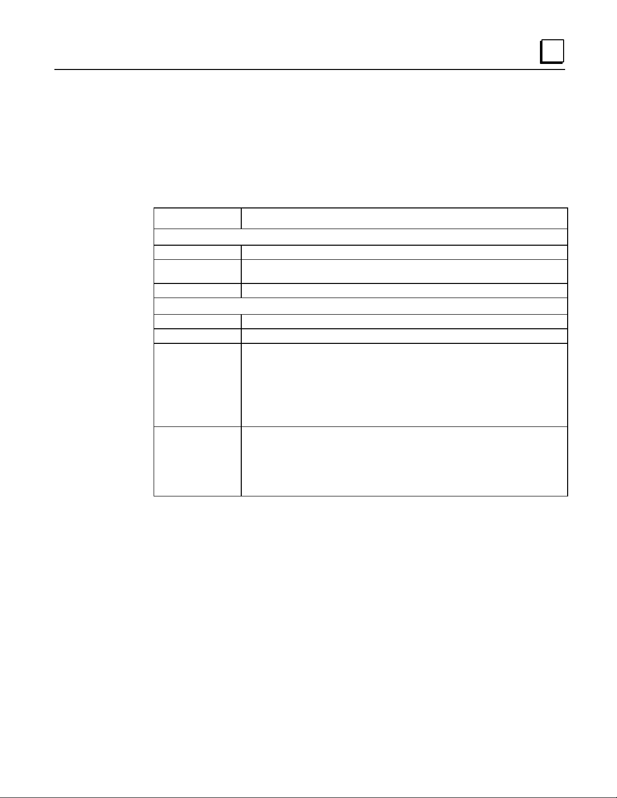
Table 5 - 1. Insulation Resistance Readings
Reading Description
Infinity
< infinity but > 20 megohms
< 20 megohms
_1 megohm
Excellent insulation. No effect from coolant. Inspection period may be lengthened.
Good insulation; however, the insulation has been affected, probably by coolant. Continue
to monitor until a pattern is established.
Insulation is deteriorating and should be monitored closely. Continue to check weekly.
Insulation system has failed. Determine the source by disconnecting the motor power plug
or leads and checking the motor directly. If the motor resistance is low, replace the motor.
If the motor resistance is not low, check the plug or terminal box. If the plug or box is wet,
dry it out, retest, and take action to prevent liquid from entering the plug or box.
Note
Any subsequent reduction of insulation resistance will give advance notice of a
possible motor failure. The motor may function to zero ohms as long as it is the
only motor on the system with low ohms; but such operation is not recommended.
Servo or Spindle Amplifiers
Check and clean these items every six months, or more often if contamination has built up.
Carefully clean using factory air, a vacuum cleaner, and/or cleaning solvent and a clean, dry cloth.
• The cooling fan for the spindle amplifier and for the servo amplifier, if provided.
• The heat sink cooling fins.
If coolant is on the amplifier, check the enclosure seal for defects that are allowing coolant into
the enclosure. Possible defects might include missing or deformed gaskets or missing filters.
Correct or replace the missing or deformed items.
If there is coolant on the electronic boards, carefully remove the coolant. The contaminants may
damage components and/or cause shorts on the boards.
Modification to the Motor
In IP67 servo motors, changing the encoder or encoder connector direction will disturb the
materials used to provide additional protection. In the case of the end cap, a liquid seal material
equivalent to Three Bond #1215 is used. The encoder connector has a flourorubber-type gasket
between it and the encoder cover.
New materials should be applied to cleaned surfaces in order to attempt to regain the original
production integrity. However, this cannot be verified unless the motor is subjected to tests
similar to the ones defined by IEC for the appropriate protection level.
5 - 4 Servo and Spindle Motors Exposed to Liquids - April 1999 GFK-1046E
Page 25

M
Index
A
Air-Over Fan, 3-4
B
Boot System, 3-2
Replacing the boot, 3-3
Rotating the boot, 3-2
C
Cable Connectors, 1-2
Cables, Severe Duty, 2-3, 2-4
Connectors, Cable, 1-2
Coolant and its effect on a motor, 3-4
D
Drains, 3-4
E
Exposure to Liquids, 2-5
Machine Runoff Checklist, 4-1
Maintenance, Preventive, 5-1
For drives in a normal environment, 5-2
For drives in a wet environment, 5-3
Motor Modification, 5-4
MS Connector Kits Supplied by GE Fanuc, 2-2
O
Oil Seals, 1-1
P
Pressurization, 3-4
Preventive Maintenance, 5-1
Protection Standards, 1-3
S
Seals, Oil, 1-1
Severe Duty Cables, 2-3, 2-4
Standards, Protection, 1-3
F
Fans, 3-4
I
IEC Standards, 1-3, 3-3
IEC Standards for Servo Motors, 1-4
IEC Standards for Spindle Motors, 1-4
Insulation Resistance Readings, 5-4
L
Liquids, Exposure to, 2-5
GFK-1046E Index-1
Page 26

GE Fanuc Automation North America, Inc., Charlottesville Virginia
 Loading...