

Page 1

OPERATION MANUAL
Back to Home
FH550SX / FH630SX
HORIZONTAL MACHINING CENTER
F
ANUC - 30i
(
,31i
)
TOYODA MACHINE WORKS, LTD.
Page 2

You are requested to read this manual thoroughly, and comprehend its contents fully prior to
starting the operation of the machine
You are also requested to keep this manual in your designated place in order to get a help of the
manual
T
ransfer of this machine
.
.
Follow the steps below without fail when you transfer this machine to someone else
-
Give this manual and attached manuals to the transferee
-
Refer to the warning labels, and confirm them all
-
If you find there is no label, nor manuals, request for them to us
If you transfer the machine to someone, never fail to inform us of the transferring
You are requested to obey the followings
-
This machine may be in the category of restricted items under the ?Foreign Exchange and
Foreign Trade Control Law of Japan?
To export this machine you must get the export license according to the law
-
This machine was manufactured originally according to laws, regulations and standards of the
country, or the area
This means that you are not allowed to export it to any other country or area where law, regula
tions and standards are different from those of the original country or area
.
;
.
.
.
.
.
.
.
.
Warranty
Free-of-charge repair
-
A failure or damage resulting from using properly the machine according to the operational standards
(
described in the manual),
the warranty period
.
manuals and indicating labels may be repaired free of charge only if it is within
-
-
The warranty may cover only the main body of the machine delivered
The warranty does not cover the direct or indirect loss caused by a failure
-
The warranty period is one year, starting from the acceptance date of the machine after its delivery
Pay repair
-
Repair after the warranty period is charged
Despite the effective warranty period the repair described below is charged
1.
Any failure or damage resulted from the misapplication by a customer, or modifying or repairing by a
customer without our consents
2.
Unexpected failure or damage arising from a fire, act of God, lightning or abnormal voltage
3.
Failure or damage due to an improper handling such as a fall at the time of transporting or moving at a
customer?s
4.
Failure or damage caused by a customer who does not follow the handling procedures
5.
Consumption, abrasion or deterioration of expendables
6.
The malfunction and damage which were produced using the other oil when there was designation oil
Moreover, the malfunction and damage which were produced since the oil with which a consistency and
the purpose of use are different was used even when there was no designation oil
.
.
.
.
.
.
.
.
.
Introduction to this manual
-
This manual is subject to change without notice when this type of machine and its manual need improving
You are requested to be generous to a small discrepancy, if any, between the machine and its manual
If you find a difference between the machine and its manual, or if you have a question, please let us know
.
.
.
.
.
Page 3

Disposal
Dispose of the machine itself and its peripherals in accordance with the laws established by the country
and relevant administrative bodies
1. Disposal of the Machine and Peripherals
.
The disposal work must be entrusted to a specialist contractor
Specialist knowledge is required to disassemble the linear motor that drives wheel feed
Ask a person who has been trained in the disassembly and assembly of linear motors to do this work
When disposing of the accumulator, release the nitrogen gas from it, then disassemble it in such a way
that it cannot be reassembled
Sort parts for disposal on the basis of your own in-house regulations, and have a specialist contractor do
the disposal work from time to time
If you have any questions about the materials that parts are made of, or other matters, please contact us
This system may include devices which use CFC as the refrigerant
When CFC is used in a device, it is stated on the name plate of the device
It is prohibited to release kinds of CFC gas in the atmosphere by the CFC Recovery and Decomposition
Law
.
When disposing a device that uses CFC, you need to ensure that the gas is recovered safely by a
contractor who is authorized to recover kinds of CFC, Category 1,
.
.
.
.
.
by the municipal authority
.
.
2. Disposal of Consumable Parts
Sort the parts according to your in-house rules, and entrust the disposal work to a specialist contractor
from time to time
(1) Coolant
(2) Chips
(3) Spent lubricating oil and hydraulic oil
(4) Battery for memory back-up
.
.
.
When disposing of the battery for memory back-up (lithium battery),
handle the batteries in accordance with any local governmental regulations
(1)
Do not mix batteries up with each other and avoid the possibility of shorting by putting the each
battery into a separate plastic bag
(2)
Ensure that the container in which the batteries are collected is made of an insulating material
(3)
Make sure the batteries are not made wet by rain or other water
(4)
Do not mix the batteries with items identified as hazardous under the fire laws, or place these
items near the batteries
(5)
Do not place the batteries near fire or in any location where they will be subject to high tempera
tures
.
(6)
Do not disassemble the batteries, heat them, or throw them into fire
.
.
abide by the following points and
.
.
.
.
-
Page 4

FOREWORD
This operating manual was created in order to let you know about an everyday handling and safety matter of
horizontal machining center FH
This operation manual consists of the ?Safety Manual? and ?Operation Manual? mainly for the operators who
will use our horizontal machining center FH
tional safety are described in the former manual, while the contents regarding machine operation are de
scribed in the latter manual
Please note in advance that some of the optional functions described in this operation manual may not be
included in your machine
If necessary, refer the following documents as well
FH
550SX/
630
SX : Maintenance Manual
550SX/FH630
.
.
SX of our company
550SX/FH630
SX for the first time: the contents regarding opera
:
.
-
-
Page 5
BEFORE READING THIS MANUAL
1. How to See Manual
FH
550SX/
630
SX
This manual is consisted in the following constructions
3. Manually Operation
FH
550SX/
3.1 Zero Return
3.1.1 Automatic Zero Return of all axis
630
Symbols
.
CHAPTER
SX
Model
Section
Paragraph
Button, lamp etc
During the origin return
cycle, the START push
button lamp is light
.
Contents of operation
explanation etc
3-4
-
.
,
.
Page Number
Before Reading Manual
1
Page 6
BEFORE READING THIS MANUAL
Explanation of items on the previous page
FH
550SX/
630
SX
Chapter
Section
Paragraph
Model
Representation of Safety Caution Marks
This manual contains the following indications to enable you to use the machine
safely, and in order to prevent hazards to personnel and damage to property
DANGER
----------------------
----------------------
-------------------
------------------------
Failure to observe items in this category will result in death or severe
injury
.
Main Topics and title of the chapter
Sub-topics and items out of chapter
Task description and items out of chapter and section
The model name of this manual
.
Failure to observe items in this category can lead to death or severe
WARNING
CAUTION
In addition to the above, the following indications are also used in this manual
<
IMPORTANT>This is an item that requires attention during machine operation or other
injury
.
Failure to observe items in this category can lead to injuries or property
damage
work
Failure to observe such items can lead to damage to the machine
.
.
.
.
<
NOTE
>
This is information for reference during machine operation and program
ming
.
Before Reading Manual
2
-
Page 7

BEFORE READING THIS MANUAL
FH
550SX/
630
SX
Operation procedure & explanation
Buttons & lamps etc
. .......
.....
Operational procedure and explanation is described
* (1) (2)
* (a) (b)
* [
* {Cutting Feed} etc shows selectable switch
* <Power Source> etc shows lamp
*
Buttons, Lamps, etc are shown in picture or drawing
Button to be activated are shadowed, and easy to be
recognized
most current information at the time of publication. How
ever, there may be instances of configuration changes from
an actual machine, so read it carefully
•E•E•E
quential process
perform it in right order
•E•E•E ar e used when there i s several select i on
the operational procedures, and are written as per
of list
.
START] etc shows button
?TOUCH SENSOR? etc shows display on screen
.
•E•E•E ar e used t o s how the numbere.
Follow this sequence, then you can
.
.
.
.
Picture or drawing was prepared with the
.
.
title
.
.
-
Page number
.......3-4
means the 4th page in the chapter
3.
Before Reading Manual
3
Page 8

Foreword
Before Reading this Manual
1
.
Safety Precaution
1.1
Items to Keep Worker?s Safety
1.
2
Items to be Kept during the Machinery Operation and to Protect the Machine
1.
3
Safety Precaution for Each Work
1.3.
1
During Operation
1.3.
2
For Setup Change
1.3.
3
For Daily Inspection
1.3.
4
Upon an Error
1.
4
Label
1.4.
1
Warning Label Attaching Position
1.4.
2
Cautions on Warning Labels
1.
5
Relation Law, Standard, Datum
-----------------------------------------------------------------------------------------------------
------------------------------------------------------------------------------------------------
-----------------------------------------------------------------------------------------------------
CONTENTS
-------------------------------------------------------------------------------
--------------------
-----------------------------------------------------------------------------
--------------------------------------------------------------------------------------------
------------------------------------------------------------------------------------------
----------------------------------------------------------------------------------------
-----------------------------------------------------------------------
-----------------------------------------------------------------------------
-------------------------------------------------------------------------------
PAGE
1-1
1-1
1-1
1-2
1-2
1-2
1-3
1-3
1-4
1-4
1-5
1-8
2
.
Machine Outline
2.
1
General Configuration
2.
2
Controlled Axis
2.
3
Operation Panel
2.3.
1
Machine Controls Description
2.3.
2
Main Operation Panel
2.3.
3
Handle Feed Operation Panel
2.3.
4
Magazine Operation Panel
2.3.
5
Pallet Changer Operation Panel
2.3.
6
Chip Conveyor Operation Panel
2.3.
7
Lamps
2.
4
Door Interlock
2.4.1
Operator?s Door Interlock
2.4.
2
Magazine Door Interlock
2.4.
3
Pallet Changer Door Interlock
2.4.
4
Explanation of Operation Mode
3
.
Operation Method
3.
1
From Power ON to Pump ON
3.1.
1
Before Turning Power ON
3.1.
2
For Bringing the Machine into Operable Condition
3.1.
3
Pump ON
3.
2
Stopping the Machine
3.2.
1
For Stopping the Machine in an Emergency
3.2.
2
Stopping the Operation at the End of Work
3.2.
3
For Stopping the Machine during Memory-,
-----------------------------------------------------------------------------------------------------
-------------------------------------------------------------------------------------------
----------------------------------------------------------------------------------------------------
--------------------------------------------------------------------------------------------------
----------------------------------------------------------------------------
--------------------------------------------------------------------------------------
2-1
2-1
2-2
2-3
2-3
2-4
----------------------------------------------------------------------------2-16
-------------------------------------------------------------------------------2-17
-------------------------------------------------------------------------2-20
-------------------------------------------------------------------------2-22
-----------------------------------------------------------------------------------------------------2-24
-----------------------------------------------------------------------------------------------------2-25
---------------------------------------------------------------------------------2-25
----------------------------------------------------------------------------------2-25
----------------------------------------------------------------------------2-26
--------------------------------------------------------------------------2-27
-----------------------------------------------------------------------------------------------------
---------------------------------------------------------------------------------
---------------------------------------------------------------------------------
--------------------------------------------------
-----------------------------------------------------------------------------------------------------
-------------------------------------------------------------------------------------------
----------------------------------------------------------
-----------------------------------------------------------
Tape-,
and MDI-mode Operation
-----------------3-10
3-1
3-1
3-1
3-2
3-4
3-7
3-7
3-9
Page 9

3.
3
Turning Off the Power
3.3.
1
For Turning Off the NC Power
3.3.
2
For Turning OFF the Main Power
3.
4
Origin Return Operation
3.4.
1
For Returning All Axes to their Origins
3.4.
2
Each Axis Origin Return
3.4.
3
For Performing Zero Return in MDI Mode
3.
5
Feed Operate
3.5.
1
Handle Feed
3.5.
2
Jog Feed
3.5.
3
Rapid Feed
3.5.
4
Turning Operation of Table
3.
6
Spindle Rotating Operation
3.6.
1
Setting of Spindle Speed
3.6.
2
Spindle Rotating Operation
3.6.
3
Stopping the Spindle---------------------------------------------------------------------------------------3-38
3.6.
4
For Stopping the Spindle Orientation
3.
7
Magazine Operation
3.7.
1
For Rotating by Jogging
3.7.
2
For Rotating in Continuous Mode
3.
8
Mounting or Dismounting a Tool
3.8.
1
For Mounting a Tool
3.8.
2
For Pullout a Tool from the Magazine
3.
9
Tool Change Operation
3.9.
1
For Put the Tool from Magazine to Spindle
3.9.
2
For Replacing the Magazine Tool with the Spindle Tool
3.9.
3
For Stopping the Spindle Tool in the Magazine
3.
10
Pallet Operation
3.10.
1
For Turning the Pallet Manually
3.10.
2
Pallet Change
3.10.
3
Pallet Confirmation
3.
11
Discharge or Stop of Coolant, Tapping Oil, etc
3.11.
1
Coolant
3.11.
2
For Discharging Air Blow and Cleaning Air Blow
3.
12
Internal Chip Conveyor Operation
3.12.
1
For Turning the Internal Chip Conveyor
3.12.
2
For Stopping the Internal Chip Conveyor
3.
13
Take up Chip Conveyor Operation
3.13.
1
For Turning the Take up Chip Conveyor in Automatic Mode
3.13.
2
For Turning the Take up Chip Conveyor Normal Direction in Manual Mode
3.13.
3
For Turning the Take up Chip Conveyor Counterclockwise Direction in Manual Mode
-----------------------------------------------------------------------------------------------------3-19
-----------------------------------------------------------------------------------------------------3-20
-----------------------------------------------------------------------------------------------------3-70
-------------------------------------------------------------------------------------------3-13
----------------------------------------------------------------------------3-13
-----------------------------------------------------------------------------------------3-14
-----------------------------------------------------------------------------------3-15
-------------------------------------------------------------------------------------------------3-19
---------------------------------------------------------------------------------------------------3-21
--------------------------------------------------------------------------------3-22
-------------------------------------------------------------------------------------3-25
----------------------------------------------------------------------------------3-25
-------------------------------------------------------------------------------3-28
---------------------------------------------------------------------------------------------3-45
-----------------------------------------------------------------------------------3-45
------------------------------------------------------------------------------3-49
----------------------------------------------------------------------------------------3-49
------------------------------------------------------------------------------------------3-54
-------------------------------------------------------------------------------------------------3-63
----------------------------------------------------------------------------------------------3-64
----------------------------------------------------------------------------------------3-67
-----------------------------------------------------------------------3-13
-----------------------------------------------------------------3-14
--------------------------------------------------------------3-16
-------------------------------------------------------------------3-42
-----------------------------------------------------------------------3-47
------------------------------------------------------------------3-52
------------------------------------------------------------3-54
--------------------------------------------3-57
-------------------------------------------------------3-60
------------------------------------------------------------------------3-63
. ---------------------------------------------------------- 3-
70
---------------------------------------------------3-82
---------------------------------------------------------------------------3-86
---------------------------------------------------------------3-86
-------------------------------------------------------------3-86
---------------------------------------------------------------------------3-87
-------------------------------------3-87
------------------3-88
-----3-89
4
.
Auto Operation
4.
1
Operation by MDI Program
4.
2
Operation from Calling Memory Program
-----------------------------------------------------------------------------------------------------
-------------------------------------------------------------------------------------
-------------------------------------------------------------------
4-1
4-1
4-3
Page 10

4.
3
Continuous Operation
4.3.
1
4.3.
2
4.3.
3
4.3.
4
How to Continuous Operation
4.
4
Setting of Various Data
4.4.
1
To Input Tool Offset
4.4.
2
To Input Work Coordinate
4.4.
3
To Input Common Variables
5
.
Editing Program
5.
1
Display of Program List
5.
2
Program Search
5.
3
Program New Make
5.
4
Program Appends a Part, Change, Delete
5.
5
Program Delete
5.6
Each Data Input/Output by Memory Card
5.6.
1
Output of Machining Program
5.6.
2
Input of Machining Program
5.6.
3
5.6.
4
5.6.
5
5.
7
Display of WINDOW
5.7.
1
5.7.
2
5.7.
3
5.7.
4
------------------------------------------------------------------------------------------Before Processing 2 Pallets Same Workpiece
Before Processing 2 Pallets Different Workpiece
Before 1 Pallet Cycle
--------------------------------------------------------------------------------------
----------------------------------------------------------------------------
-----------------------------------------------------------------------------------------
-----------------------------------------------------------------------------------------
---------------------------------------------------------------------------------4-11
------------------------------------------------------------------------------4-14
-----------------------------------------------------------------------------------------------------
-----------------------------------------------------------------------------------------
--------------------------------------------------------------------------------------------------
----------------------------------------------------------------------------------------------
------------------------------------------------------------------
---------------------------------------------------------------------------------------------------
-----------------------------------------------------------------5-10
----------------------------------------------------------------------------5-10
------------------------------------------------------------------------------5-13
Input/Output of Offset
Input/Output of Macro
Output of Parameter
--------------------------------------------------------------------------------------5-15
--------------------------------------------------------------------------------------5-16
----------------------------------------------------------------------------------------5-17
---------------------------------------------------------------------------------------------5-18
Display Lamp Illumination
Display Function Switch
Display NC Switch
Display OP Supporter
---------------------------------------------------------------------------------5-18
----------------------------------------------------------------------------------5-19
------------------------------------------------------------------------------------------5-20
--------------------------------------------------------------------------------------5-21
------------------------------------------------------
---------------------------------------------------
4-5
4-5
4-5
4-6
4-6
4-8
4-8
5-1
5-1
5-2
5-4
5-6
5-8
6
.
Daily Check
6.
1
Check before Turning Power ON
7
.
NC Function List
7.
1
Preparatory Function (G code
7.
2
Auxiliary Function (M code
7.2.
1
Auxiliary Function List
7.2.
2
Explanation of Auxiliary Function
7.
3
Spindle Speed Function (S code)-----------------------------------------------------------------------------7-15
7.
4
Cutting Feed Rate Function (F code
7.
5
Tool Offset Amount
7.
6
Tool Function (T code
-----------------------------------------------------------------------------------------------------
------------------------------------------------------------------------------
----------------------------------------------------------------------------------------------------) -------------------------------------------------------------------------------- 7-1
)------------------------------------------------------------------------------------ 7-6
-------------------------------------------------------------------------------------
-----------------------------------------------------------------------
) ------------------------------------------------------------------------ 7-
(H/
D code
) -------------------------------------------------------------------------------- 7-
) ------------------------------------------------------------------------------------------ 7-
6-1
6-1
7-1
7-7
7-9
15
15
15
Page 11

8
.
Special Function
8.
1
Heat Displacement Compensation Function for Spindle
8.
2
Tool Breakage Detection
8.2.
1
Magazine Tool Inspection
8.2.
2
Cycle Diagram
8.2.
3
Tool Inspection Unit Jog Mode
8.2.
4
Machining Program
8.2.
5 M06
8.2.
6
Tool Inspection Traveling Amount Calculation Program
8.2.
7
Tool Inspection Unit Parameter
-----------------------------------------------------------------------------------------------------
-------------------------------------------------
----------------------------------------------------------------------------------------
---------------------------------------------------------------------------------
-----------------------------------------------------------------------------------------------
---------------------------------------------------------------------------
-----------------------------------------------------------------------------------------
Macro Program
---------------------------------------------------------------------------------------
---------------------------------------------
--------------------------------------------------------------------------
8-1
8-1
8-3
8-3
8-4
8-4
8-5
8-6
8-8
8-9
Page 12

1. SAFE PRECAUTION
1.1 Items to Keep Workers Safety
(1)
The factory controller (equipment controller) must prohibit everyone other than those
who have undergone sufficient safety education, from entering the factory and the
machine installation site for safety reasons. If those who have not undergone sufficient
safety education carelessly enter the factory and the machine installation site, a fatal
accident may result
(2)
Prior to machine operation, always confirm the safety of the other personnel in the
immediate vicinity of the machine. Negligence of this precaution may lead to accidents
such as getting caught in rotating parts or getting jammed between movable parts
resulting in injuries
(3)
Do not leave objects on the floor near the machine. Keep the area organized and tidy
Also, keep the area clean so that the floor is free from oil or water. Negligence of this
precaution will lead to the operators or other people slipping and falling, resulting in
injuries
(4)
When you walk around the machine, watch your step as you may stumble on the lever
of a leveling block, foundation parts or other object, and get injured
(5)
Do not operate the machine when the protective covers, interlocks, or any other safety
devices have been removed. When the machine is operated with these devices re
moved, it can move in an unexpected way and can cause accidents, resulting in
injuries
.
.
.
.
FH
.
550SX/
630
-
SX
,
.
(6)
Wear clothes or protective gear so that you can work safely
operation in mind and make sure of safety before starting work as you may get en
tangled in the machine or be unexpectedly injured
(7)
Do not enter the machine working area while it is in operation. Negligence of this
precaution may lead to accidents such as getting caught in rotating parts or getting
jammed between movable parts, resulting in injuries
(8)
Do not turn on the circuit breaker while a door of the control cabinet is open as you
may carelessly touch devices in the control cabinet, and get an electric shock or
burns, resulting in serious injuries and possibly leading to death in some cases
(9)
Receive education according to the manual or the like before operating or servicing the
machine. If those who have not received sufficient safety education carelessly touch
the machine, a fatal accident may result
(10)
Only suitably qualified personnel must operate a crane or a forklift, and perform slinging
work. If those who have not received sufficient safety education try to do such work, a
fatal accident may result
.
.
.
.
, and keep the correct
-
.
1.2 Items to be Kept during the Machinery Operation and to Protect the Machine
(1)
Do not change the settings of the parameters as they have been set to your specifica
tions before shipment of the machine
.
-
(2)
Check that switches and lamps function properly before operating them, or the ma
chine may be damaged due to a malfunction
(3)
When moving each axis in the manual mode operation, make sure that there are no
obstacles between the cutting tool or spindle head and the table, jigs and workpiece
Negligence of this precaution will lead to mechanical damage
1-1
.
.
-
.
Page 13

1. SAFE PRECAUTION
1.3 Safety Precaution for Each Work
1.3.1 During Operation
(1)
Before starting the machine, familiarize yourself with the locations of [EMERGENCY
STOP] buttons so that you can press them as a reflex, at any time and anywhere
Having obstacle objects in front of the [EMERGENCY STOP] buttons will delay the
timing of pressing the button and can lead to injuries and mechanical damage
(2)
Never touch the switches, buttons, and keys with wet hands. Negligence of this
precaution can lead to electrocution if the grounding effect is insufficient or if there is
any electric leak
(3)
Confirm that there are not obstacles within the machine?s working area before operating
the machine. Negligence of this precaution will lead to accidents such as getting
caught in rotating parts or getting jammed between movable parts, resulting in injuries
(4)
Refer to the - Tooling Manual - for details regarding the area of interference within the
axis travel range
(5)
When carrying out machine operations in the manual mode, never operate the
pushbutton switches located on the operation panel while your feet, legs, hands or
other parts of the body are touching the machine. Negligence of this precaution will
lead to accidents such as getting caught in rotating parts or getting jammed between
movable parts, resulting in injuries
.
.
FH
550SX/
.
630
.
SX
.
.
(6)
Do not place your hand or body inside the guard while a pallet is being unloaded. Being
trapped inside the machine will lead to serious injuries to your body
(7)
Before turning the power on, close the door of the control cabinet and the lid of the
terminal box, or you may get an electric shock or burns, resulting in serious injuries
and possibly leading to death in some cases
1.3.2 For Setup Change
(1)
Before removing or mounting a workpiece, check that the [NEXT CYCLE START] lamp
has gone out, and that the pallet changer has stopped
(2)
Change a tool on the side of the magazine. As it is hard to obtain a safe footing on the
spindle side, you may tumble or get injured on the tool edges
(3)
During the setup change work and when handling a heavy workpiece, take a rest
halfway as necessary, taking the weight of the workpiece into account
(4)
To handle a tool, secure a safe footing taking its weight and the gripping position into
consideration, and take care not to drop it. For a heavy tool, take necessary actions
such as hoisting it with a ceiling crane or the like. If not, you may tumble or get injured
on the tool edges
.
.
.
.
.
.
1-2
Page 14

1. SAFE PRECAUTION
1.3.3 For Daily Inspection
(1)
Before entering the machine without an external cover, turn the power off. Otherwise, if
you are trapped in the machine, you will receive serious injuries to your body
(2)
Before entering the machine, wear safety shoes, and watch your step during work as
the floor is wet and slippery with oil or coolant so you may tumble and get injured
(3)
To clean away chips, do not touch them directly by hand. When using compressed air
wear protective goggles, or you may be cut by chips or your eyes may be injured
(4)
Before entering the machine or pallet changer to clean away chips, clean off chips
water, oil and the like from the footing, and secure a place where you can stand safely
or you may tumble, get injured or break a bone
(5)
When you open or close the control cabinet door, operator door, and magazine door, be
careful so that your fingers or other parts of your body are not caught
(6)
Do not splash oil, water and so on over the operation panel, terminal box or the like as
you could receive an electric shock due to power leakage or a machine failure will
result
.
FH
550SX/
.
.
.
630
.
.
SX
,
,
,
1.3.4 Upon an Error
(1)
Upon an error with the machine, press the [EMERGENCY STOP] button and follow the
instructions of qualified personnel appointed by your company. If those who have not
received sufficient safety education carelessly touch the machine, a fatal accident may
result
.
1-3
Page 15
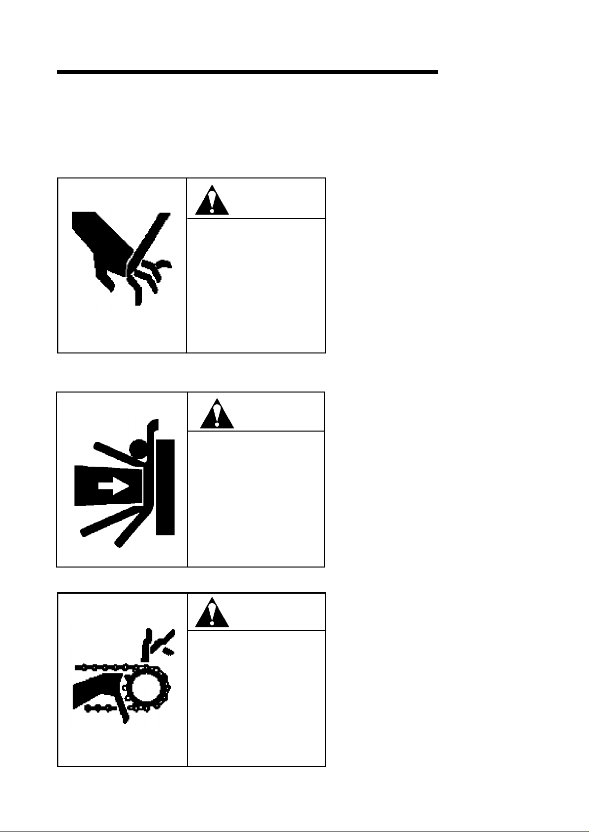
1. SAFETY MANUAL
1.4
.
Label
1.4.
1
Warning Label Attaching Position
FH
550SX/
630
SX
Type Warning label No
A PD-CA111004
B PD-CA611002
C PD-CA611004
D PD-CA611007
E PD-CA011039
F PD-CA016002
G
29-08080224-1
H PD-CA010014
I PD-CA011016
J
20-99951984-0
-A Hand may be injured
-A Body may be crushed (
-A Hand may be crushed Crush the hand Coolant tank
-A Body may be crushed (
-B Tool limit M/
-A Total name plate Control panel
-A Slippery Operator?s door
-B Body may be crushed (
.
Hand may be injured Operator?s door
High voltage
Contents Attached position
M/
G door
rear of machine) Rear panel
interlock
don?t remove
)
Operator, P/
G door
)
Each door
Control panel, Spindlehead
Coolant
1-4
C door
,
Page 16
1. SAFETY MANUAL
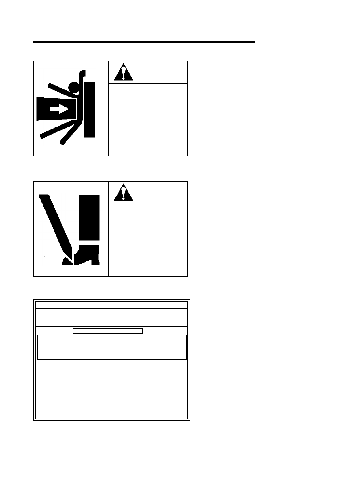
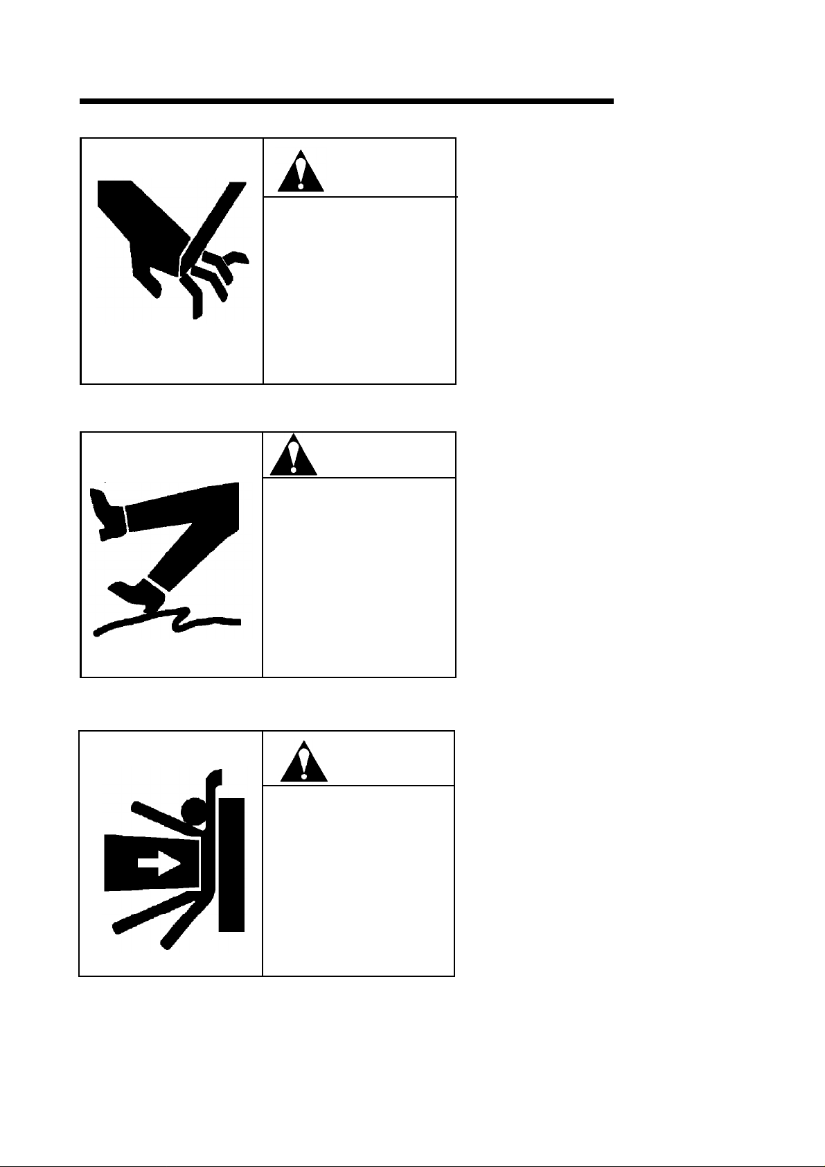
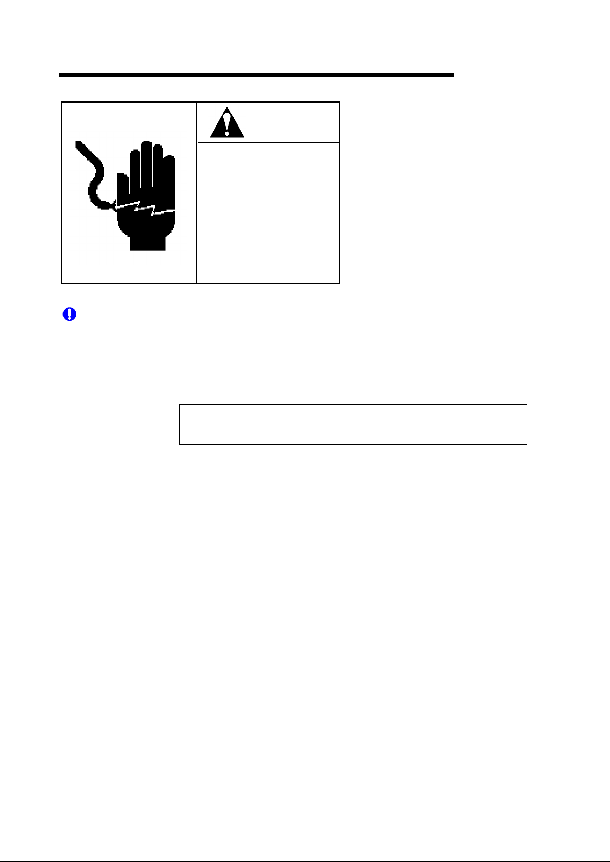
1.4.
2
Cautions on Warning Labels
FH
550SX/
630
SX
The warning labels show in the table below are attached to this machine
Fully understand the contents of each warning label and observe the mentioned items
<
Factor
>
WARNING
It cannot be defined when this machine starts
to operate during automatic operation
TOOLS INSIDE ENCLOSURE MAY
<
MOVE AUTOMATICALLY WITHOUT
WARNING
TOOLS CAN CAUSE SERIOUS CUTS
AND INJURIES
DO NOT OVERRIDE THE SAFETY
INTERLOCK
.
.
.
Incidental Results
The tool inside the magazine may cause
serious damage to the human body
<
Method of avoiding these accidents
Do not enter the safety fence during auto
matic operation.The safety interlock should
>
not be made invalid (OFF
.
.
.
.
>
).
PD-CA111004-A
<
Factor
>
DANGER
TOOLS AND PARTS IN THIS AREA
MAY MOVE AUTOMATICALLY
WITHOUT WARNING
CAN CAUSE SEVERE CRUSHING
INJURIES AND DEATH
DO NOT ENTER THIS AREA
UNLESS YOU CAN DO SO SAFELY
LOCK OUT POWER WHEN
WA
RNING IN THIS AREA
.
.
.
If cannot be defined when this machine starts
to operate during automatic operation
<
Incidental Results
>
If your hand or leg is caught in the machine
serious damage may be caused to the
human body, thereby leading to death
.
<
Method of avoiding these accidents
It is not allowed to get inside the machine
rear section with the power switch ?ON?
.
.
>
.
PD-CA611002-A
-
,
WARNING
CHIP CONVEYOR HAS NIP AND
PINCH POINT HAZARDS
MAY CAUSE SERIOUS HAND
INJURIES
PROCEED WITH CHIP CONVEYOR
CLEANING AND INSPECTION AFTER
POWER OFF
.
.
.
PD-CA611004-A
1-5
<
Factor
>
Your hand or leg may be caught in the chip
conveyor
<
Incidental Results
If it should be caught in the machine, dam
.
>
ages, such as a blow and bone fracture may
be caused
<
Method of avoiding these accidents
.
>
Proceed with chip conveyor cleaning and
inspection after power OFF
.
Page 17
1. SAFETY MANUAL
PALLET CHANGER MAY MOVE
AUTOMATICALLY WITHOUT
WARNING
CAN CAUSE SEVERE CRUSHING
INJURIES
DO NOT WORK IN THIS AREA
UNLESS YOU CAN DO SO SAFELY
DO NOT OVERRIDE THE SAFETY
INTERLOCK
WARNING
.
.
.
PD-CA611007-A
CAUTION
FH
550SX/
<
Factor
>
It cannot be defined when this machine starts
to operate during automatic operation
<
Incidental Results
>
If your hand or leg is caught in the machine or
contacts the machine, serious damage may
be caused to the human body
.
<
Method of avoiding these accidents
.
The safety interlock should not be made
invalid (OFF
<
Factor
).
>
Do not exceed following tool specifications
630
.
>
SX
.
DO NOT EXCEED FOLLOWING TOOL
SPECS
.
LENGTH
WEIGHT 27kg
MOMENT 29N?m
IMBALANCE WEIGHT 70kg
EXCEEDING SPECS
MAY CAUSE TOOLS TO FALL AND
RESULTS IN SEVERE INJURIES
545
mm
.
PD-CA011039-B
GENERAL SAFETY CAUTIONS
1. Read all manuals and receive the necessary training before operating or
sevicing this machine.
2. Receive special training, required for a machine with manipulators and
memory equipment before operating machine.
SAFETY OPERATION CAUTIONS
1. Use proper safety equipment.
2. Confirm that all safety guards and switches are in position. Do not attempt to
operate or service without proper training.
3. Confirm that no one is in machine?s working area before starting machine.
4. Emergency-stop machine upon trouble. Recovery procedure should be
performed by authorized personnel only.
A. CAUTIONS PERTAINING TO
MACHINE OPERATION
1. Do not open doors and covers on
electrical boxes.
2. Do not touch any moving parts.
3. Watch your step and hand position
when loading and unloading parts, and
whe n m a nua l ly oper atin g t he
machine.
4. Power should be turnd off prior to
the cleaning of chips or machine.
5. Don?t touch by hand to chips or
cutting tools? edge.
B. CAU TIONS P E RTAIN ING TO
MAINTENANCE AND INSPECTION
1. Maintenance and inspection should
be performed by authorized personnel
only
2. Turn off air and electrical power before
servicing machine.
3. Always turn off primary power before
servicing machine.
4. Support the vertical travelling unit with
a pole when service it.
5. Watch your step.
<
Incidental Results
>
Exceeding specifications may cause tools to
break and result in severe injuries
<
Specifications
Length
545
>
mm
.
Weight 27kg
Moment 29N?m
Imbalance weight 70kg
<
Training
>
Before machine operation start, the engineers
handling this machine should receive ?special
training?
<
.
Hints on operation
>
Wear working clothes and protectors that
enable safe operation, and always start
correct machine operation after checking for
operational safety
<
Caution
>
During operation, avoid dangerous action
.
.
Maintenance check should be carried out by
the qualifed person, and every description
should be observed strictly
.
PD-CA016002-A
1-6
Page 18
1. SAFETY MANUAL
TOOLS CAN CAUSE SERIOUS CUTS
AND INJURIES
HANDLE CAREFUL
CAUTION
.
LY.
29-08090224-1
CAUTION
FH
<
Factor
>
The tool and cutter are sharp
<
Incidental Results
>
550SX/
.
630
If your body touches the tool, damage may
be caused
<
Method of avoiding these accidents
Carefully handle the tool
<
Factor
The floor is slippery
.
>
.
>
.
SX
WET AND SLIPPERY SURFACE
SLIPPING CAN CAUSE BRUISES OR
FRACTURES
WATCH YOUR STEP AND WEAR
SAFETY SHOES
.
.
.
PD-CA010014-A
DANGER
TOOLS AND PARTS IN THIS AREA
MAY MOVE AUTOMATICALLY
WITHOUT WARNING
CAN CAUSE SEVERE CRUSHING
INJURIES AND DEATH
TURN OFF THE POWER AND STOP
MACHINE BEFORE TAKING COVER
OUT
.
DO NOT OPERATE MACHINE WHEN
COVER IS TAKEN OUT
.
.
.
<
Incidental Results
>
You may fall down, being injured or breaking
your bone
<
Method of avoiding these accidents
.
>
Wear the safety shoes, and perform operation
while watching your step
<
Factor
>
.
Do not operate machine when cover is taken
out
.
<
Incidental Results
If your hand or leg is caught in the machine
>
,
serious damage may be caused to the
human body, thereby leading to death
<
Method of avoiding these accidents
Do not take out the cover
.
.
>
PD-CA010016-B
1-7
Page 19
1. SAFETY MANUAL
HAZARDOUS
HIGH V
OR CAUSE DEATH
DO NOT OPENARY DOOR OR
COVER WHILE IN OPERATION
ONLYQUALIFIED PERSONNEL
PERFORM MAINTENANCE AFTER
LOCKING OUT POWER
DANGER
!
OLT
AGE MAYSHOCK, BURN
.
.
29-99951984-1
FH
<
Factor
550SX/
>
630
SX
Dangerous high voltage is applied to the
machine
<
Incidental Results
.
>
Electric shocks or burns may cause serious
damage to the human body, thereby leading
to death
.
<
.
Method of avoiding these accidents
>
Do not open the doors and lids during
TO
operation.Maintenance check should be
carried out by the qualified person after the
power is turned OFF
.
<
IMPORTANT
Check to see that the warning label is attached when the product is delivered
>
Clean the machine periodically in order to clearly read the description on the label
If the warning label cannot be read or it is missing, immediately ask us to supply the label
and attach it at your end
In that case, select a warning label from the warning label number list shown above accord
ing to the machine specifications to request us to supply it
When reselling your machine, always inform us of the company to which
you resell the machine
1.
5
Relation Law, Standard, Datum
A personnel, who may operate the machine (Examples : Industrial Robots, Carrying - IN
OUT Loader etc
sequence controller and fixed sequence memory storage are included, and makes a
complex and / or automatic motion / a swing motion / a extension and construction / an up
and down motion / right-&
memory storage, must get a special education due to the rules for Industrial Safety and
Health Act the third clause of Article 59.
prepared at your country or at your company to the personnel, who will pursue the operation
/
maintenance etc
.
.
.
.
.),
that has manipulators and has memory storage, in which rewritable
leftward transportation according to the information out of
On this kind of machines, give a special education
.
.
-
/
1-8
Page 20
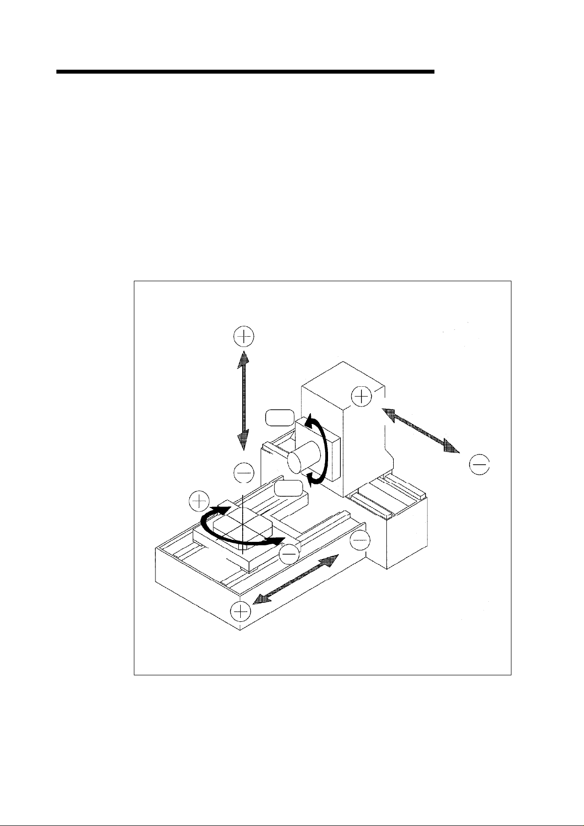
2. MACHINE OUTLINE
2.1 General Configuration
The basic configuration of the machine is described below.
The data is not only input by the key but data input/output with the external equipment via the
memory card is also available.
The number of NC controllable axes is 4, and 3 axes can be controlled simultaneously: these
NC control axes are X axis - longitudinal movement of column, Y axis - vertical movement of
spindle head, Z axis - transverse movement of table, and B axis - table rotation.
Spindle rotation can be set steplessly by the use of AC servo motor.
FH
550SX/
630
SX
Y-axis
B-axis
CW
X-axis
Spindle
CCW
Z-axis
2-1
Page 21
2. MACHINE OUTLINE
2.2 Controlled axis
Z-
axis
X-
axis
Y-
axis
FH
550SX/
630
SX
Axis Traveling direction
Longitudinal
X
movement of column
Vertical movement of
Y
spindlehead
Transverse movement
Z
of table
NC table rotation
B
1
•‹ table rotation
Spindle rotating speed (
Standard S35~S6,
Min. command
increment
1/
1000
mm
1/
1000
mm
1/
1000
mm
1/
1000
•‹
1
•‹
min-1)
000
Rapid traverse rate
(m/
min
)
60 m/min
60 m/min
60 m/min
90
ø/2
sec
. -------
90
ø/2
sec
. -------
Cutting speed (mm/min
1~30,000
1~30,000
1~30,000
)
2-2
Page 22
2. MACHINE OUTLINE
2.
3
Operation Panel
2.3.
1
Machine Controls Description
FH
550SX/
630
SX
This machine has Main Operation Panel and other operation panels of Handle
Operation,
Tool Magazine, Pallet Change Operation and Chip Conveyor Operation
Feed
.
2-3
Page 23
2. MACHINE OUTLINE
2.3.2 Main Operation Panel
2.3.2.1 NC Operation Panel
FH
550SX/
630
SX
2-4
Page 24
2. MACHINE OUTLINE
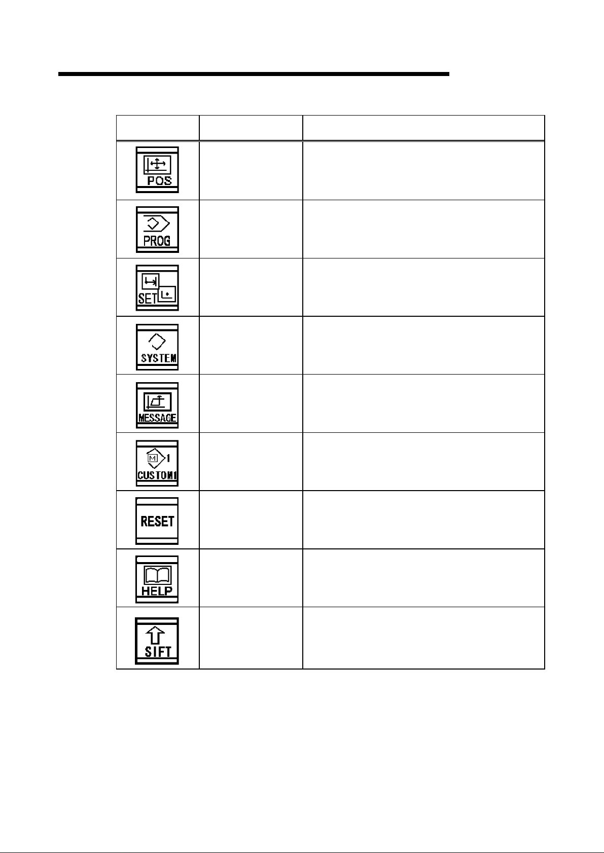
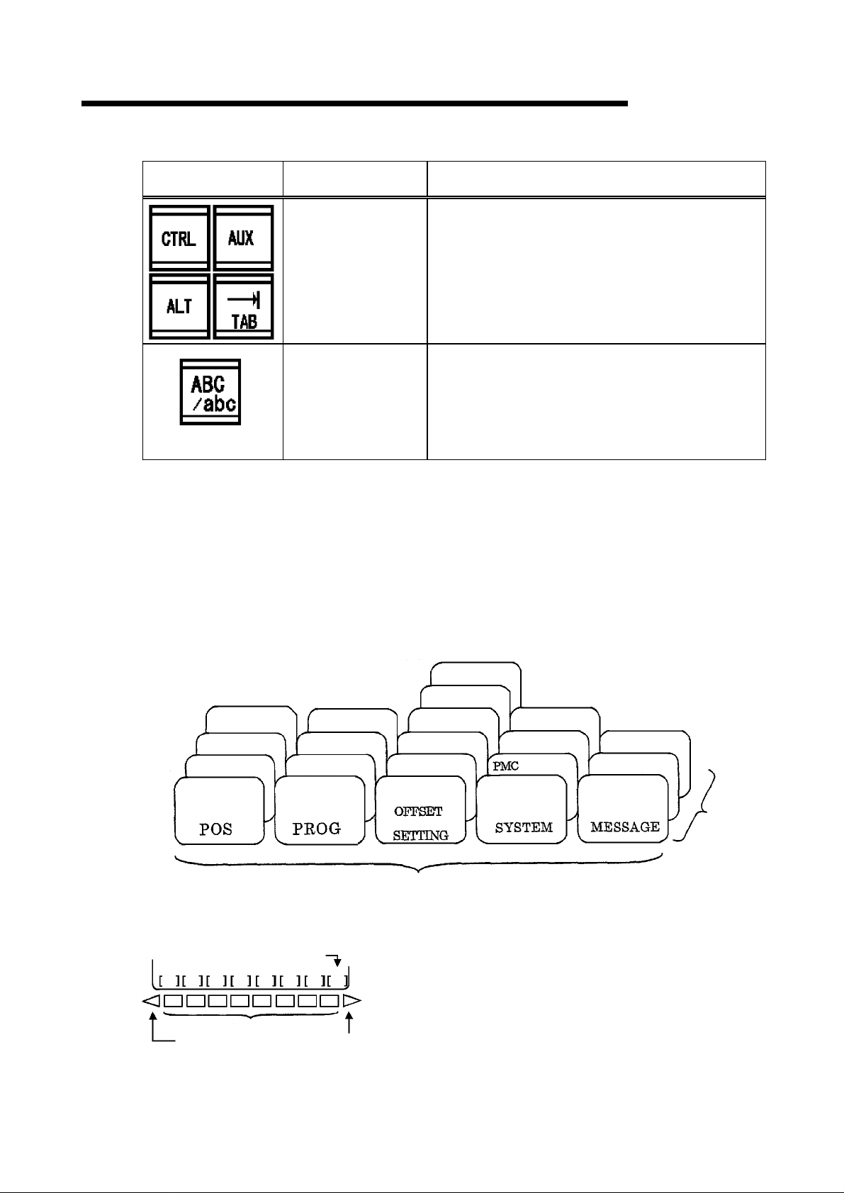
POS
Key
key
Nam
FH
550SX/
e
Press
thisto
display theposition displayscr
Descripti
on
630
een
SX
.
PROG
key
OFFSET
SETTIN
SYSTEM key
MESSAGE key
CUSTOM key
RESE
T k
G k
ey
ey
Theviewin
registered intome
A viewi
the amount of workpiece zero offsets, a macro
frequency, tool
Press
A viewi
compensation, self-diagnostics data, etc. are
performed
A viewi
message, and alarm hysteresis is performed
OP s
T
his
cancel release of an alarm etc
•E If a butt on i s pushe, NC will be reset and it will
be in an initial state
g a
nd editof aprogramwhi
mory ar
ng andsetup ofthe
-life data, etc. are performed
thisto
display thesystemscreen
ng andsetup of a
.
ng ofan
upp
orterscr
buttonispushedto res
alar
een is
e pe
para
m me
ssage,PCala
displayed.
.
ch are
rfor
med
.
amountof tool
.
meter, apit
et an
NC unitfora
.
offsets
.
ch error
rm
.
,
HELPkey
SH
IFT
key
T
his
keyisus
as control method and alarm contents generated in
CNC when MDI control method is not sure
Theaddress key by
is in one key
inputted if a shift key is pushed
right letter can be inputted, ? ^ ? is displayed on a
screen
2-5
ed torequestdi
.
.
splay forsuch deta
whi
ch two l
A letter can be changed and
ette
rs were pr
.
When a lower
.
ils
inted
Page 25
2. MACHINE OUTLINE
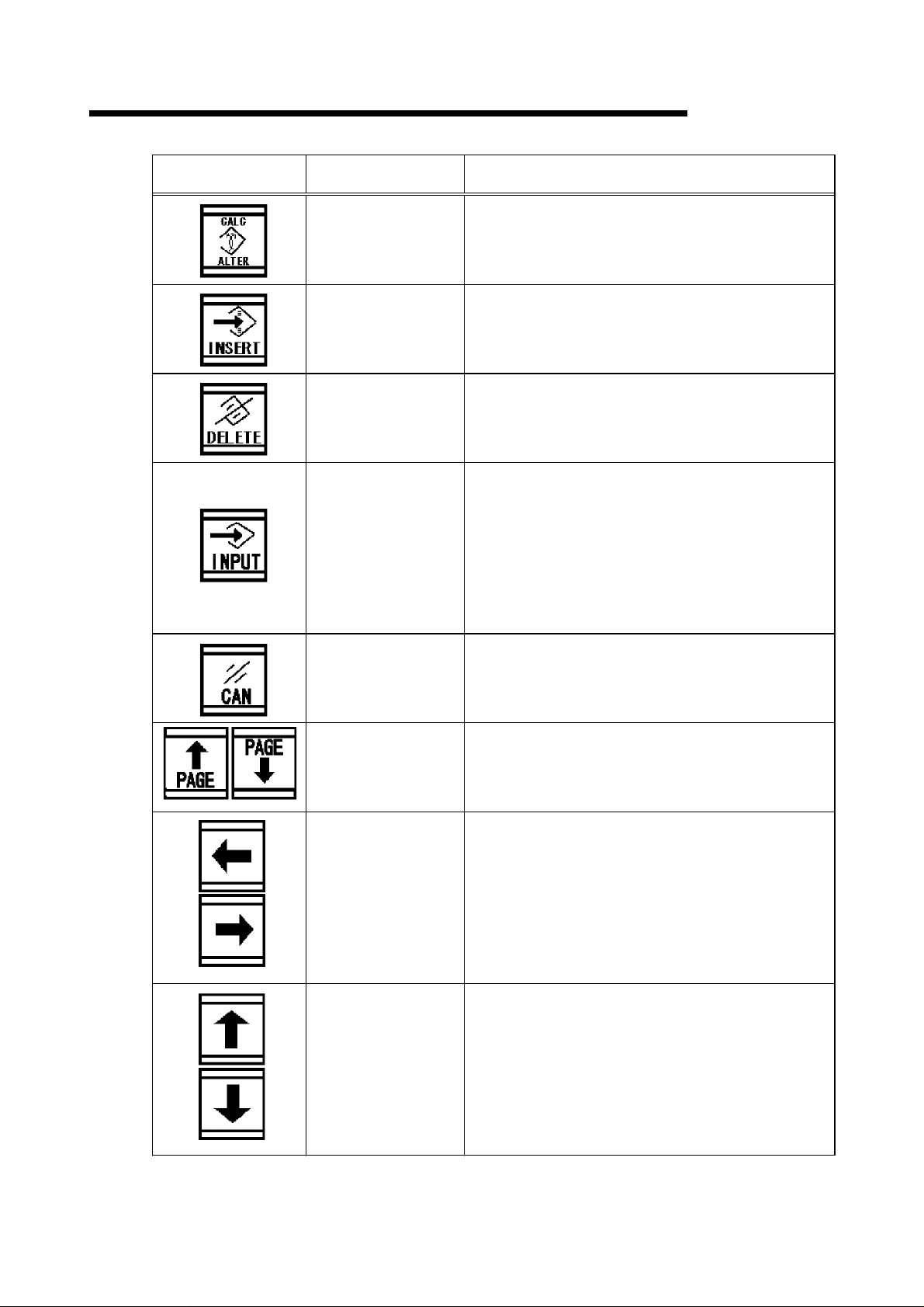
ALTER key
INSERT key
DELETE key
INPUT key
CAN key
Name Description
T
hisisa key to cha
data di
splay are
T
hisisa key to ins
ar
ea.
T
hisisa key to deleteo
di
splay ar
T
he data
the
ar
e di
offs
the
It isequ
whi
han
screen.
T
hisisa key to deleteonele
input area.
T
he letteredit m
ba
ckspac
ea.
whichpu
numeric
et airregisteretc. the informat
key inpu
che
dli
al
splayed."I
t buf
ivale
ver
may b
ng ofmoving
e.
nge the
a.
ert t
he d
n t
she
d and i
keypadare i
NPUT" keyispushe
fer.
nt to
theinput of
e u
sed.
a folderon aprogramlist
ode be
comesthe ope
dataonthecursorof the
ata ofthe datainp
he curs
nputtedt
nput
a softkey
It isusedalso f
tter
FH
550SX/
or of
thedata
he add
tedint
o a buf
d to set to
ion inputtedinto
and
of the da
ta in d
ratio
or
n of
630
ut
ress
fer,
SX
or
and
an
ata
a
PAGE change over
key
Cursor shifting key
Cursor shifting key
T
hisisa key to cha
øThe
page to
prev
iouspageorthe next p
T
hisisa key to mov
ø
A pushon
andlef
ø
In a small par
di
rectionanda reverse direct
T
hisisa key to mov
ø
A push on
upper
ø
In a
di
rectionanda reverse direct
a key m
t, and a reve
a key m
and lower,and a
large
par
nge
be pressedby keyischange
e t
he cursor.
oves
rsedirection.
titionun
e t
he cursor.
oves
titi
on unit,it
the
pag
e.
age.
cursorto theorderofri
it,
it movest
cursorto theorder
reverse direct
movest
o the right
ion.
ion.
o the right
ion.
d to the
ght
of
2-6
Page 26
2. MACHINE OUTLINE
FH
550SX/
630
SX
Name
Personal computer
function key
Upper case/Lower
case
It is used by the personal computer function of
3
10i/310iS
.
The upper case/lower case at the time of an
alphabet input are switched.
De
scripti
on
Change-over key
(1) By pushing the function key on the console panel, the soft key for chapter selection
belonging to the function is displayed on a screen.
(2) A push on one of the soft keys for chapter selection displays the screen of the chapter.
A chapter key is pushed when the soft key of the chapter which you want to display is
not displayed.
Screen configuration image
A screen structure changes with some specification of a machine.
Operation panel
Life management
Machine
Relative
Absolute
General
Monitor
List
Program
Check
Macro variable
Setting
Work offset
Tool offset
Function key
Parameter
(3) When the screen of the chapter which you want to
display is displayed, a menu key is pushed. And the
Chapter
softkey of the description to operate is displayed.
(4) A chapter key is pushed to return to the softkey for
Function
menu key
Soft key
Operation
menu key
chapter selection.
The above is the viewing procedure of a common
screen. An actual viewing procedure changes with each
screens. Refer to the operation manual instruction of
FANUC for the concrete operating procedure.
Message
Alarm
Chapter
select soft
key
2-7
Page 27
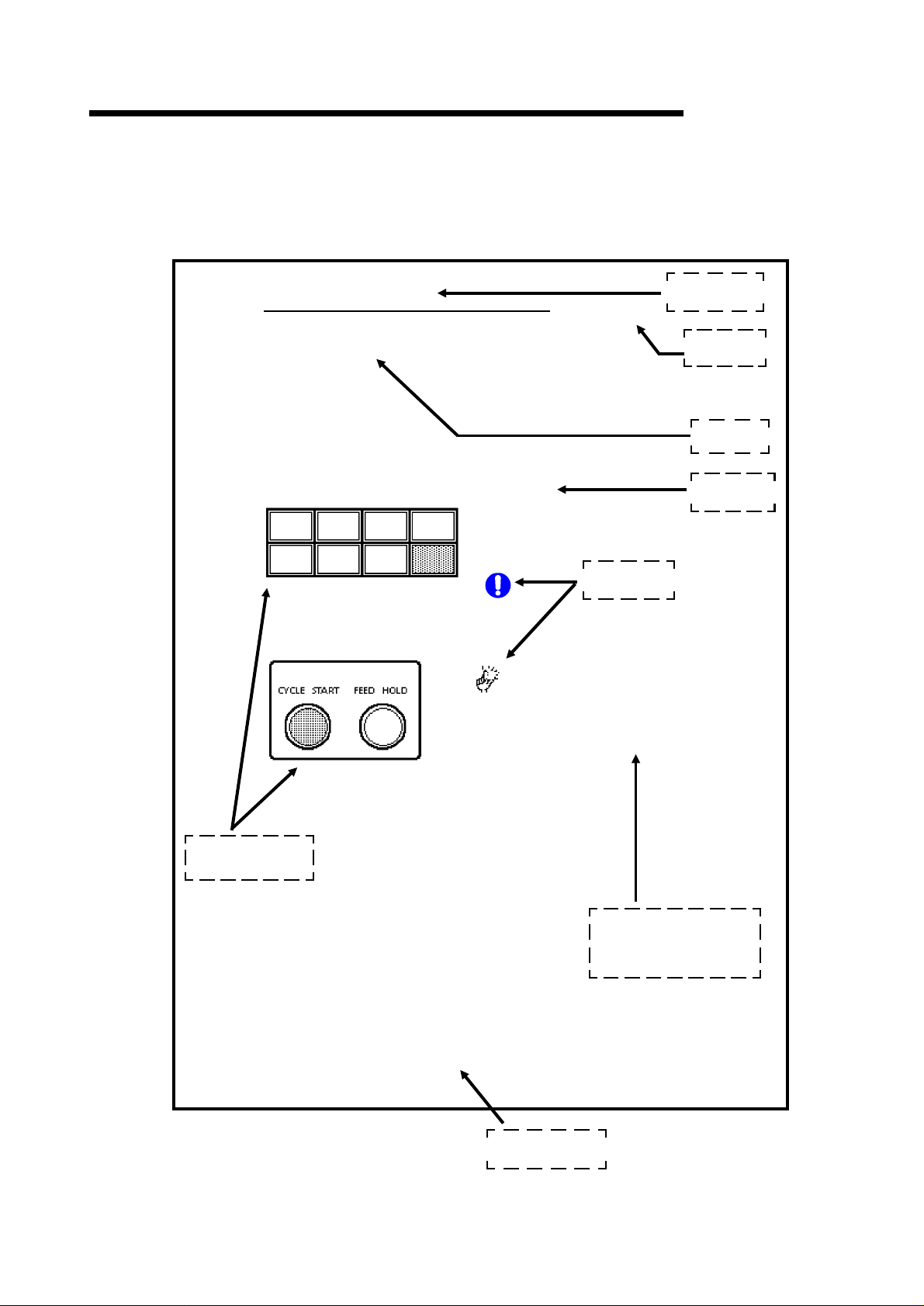
2. MACHINE OUTLINE
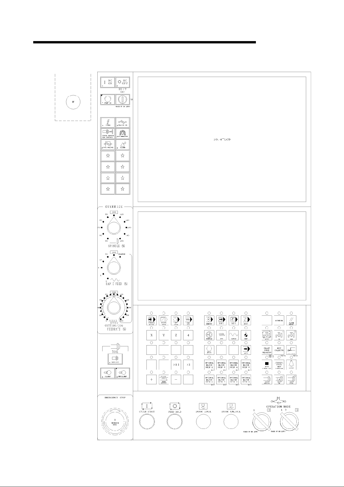
2.3.2.2 Machine Operation Panel
FH
550SX/
630
SX
2-8
Page 28
2. MACHINE OUTLINE
FH
550SX/
630
SX
Name
NC
ON
NC
OFF
EMERGENCY
STOP
PUMP
ON
button, lamp
button
(
Green
button
(
White
button
(
Red
(
Green
Function &Descri
This button is used to supply electric power to the NC device
After pushing this button, LCD
)
10
sec. NC device is thus ready to go
This button is used to shut electic power down to NC device
After pushing this button, LCD
)
has no electric power
machining or editing is active
This button is used to shut off machine power and hydraulics
After pushing this button, machine preparatory circuits are
shut off, [
)
•E This button is locked at pressed state upon activatio
•E Turn to arrowed direction(CW) to be released
This button prepares the machine for operation
•E Pressing this button starts the hydraulic pum, lubricating
)
and spindle lubricating pump
PUMP ON] turns off, and all motions stop
.
Never push this button when
.
ption
screen gets display in about
.
screen turns off, NC device
.
.
.
.
.
.
.
.
,
EDIT
ON/OFF
key switch
POWER
(
UNLOCK
TOUCH
OIN CONTACT
M/G
SENSOR
OP
OK
(
(
(
Orange
Orange
lamp
White
lamp
White
lamp
lamp
This key is used to select edit mode active or not
•E Select ON positio, then edit mode is active
•E Select OFF positio, then edit mode is not active
This lamp goes on when turning ON the handle of the
no-fuse breaker on the control cabinet
)
This lamp is used to release the lock of the operator door
)
This lamp goes on when detecting the contact between the
spindle (tool) and the table (fixture, workpiece
)
This lamp goes on when the MANUAL at magazine
operation panel
)
was selected.
.
.
.
.
).
.
2-9
Page 29
2. MACHINE OUTLINE
Name Function & Description
FH
550SX/
630
SX
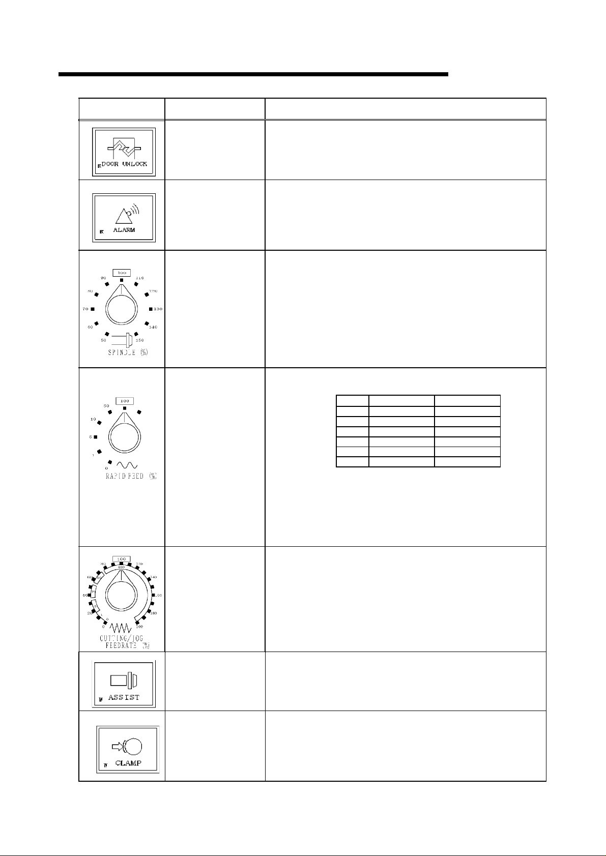
DOOR UNLOCK
ALARM
SPINDLE
OVERRIDE
RAPID FEED
OVERRIDE
CHANGE
lamp
(Red)
lamp
(Red)
selection switch
(Gray)
selection switch
(Gray)
This lamp goes on when releasing the electromagnetic type
interlock at operator?s door, magazine door and APC door
This lamp goes on when any abnormal is occurred.
This lamp blinks at alarm.
This lamp turns off when releasing the alarm or warning
condition.
•E Thi s swit ch can change t he speed fro m 50 t o 150 % of t he
programmed rotation speed (S command). But in tapping
cycle (G84), the spindle speed is fixed in 100%.
•E When t he spi ndl e speed i s max. t he speed i s fi xed t o max.
even if up the speed by the override switch.
•E When t he spi ndl e speed i s mi n. t he speed i s fi xed t o mi n.
even if down the speed by the override switch.
This selection switch changes the feed switch for G00 and
G28, namely rapid feed and Zero-return speed.
% FH550S
0% 0 mm/min 0 mm/min
1% 600 mm/min 600 mm/min
5% 3000 mm/min 3000 mm/min
10% 6000 mm/min 6000 mm/min
50% 30000 mm/min 30000 mm/min
100% 60000 mm/min 60000 mm/min
X
FH630SX
.
CUTTING/JOG
FEEDRATE
override selection
ASSIST
button, lamp
(White)
CLAMP
button, lamp
(White)
switch
(Gray)
* CHANGE
In case of turn to CHANGE position
It operates according to the % of CUTTING/JOG
FEEDRATE.
An inner side follows "RAPID FEED", an outside follows
"CUTTING FEED OVERRIDE", and it operates.
It is a switch for modifying 0 to 200% of a rate to the rate of
CUTTING FEED maximum speed (30000mm/min) and JOG
FEED maximum speed (10000mm/min). However, the midst
of a tap cycle is fixed to 100%.
Moreover, X1 changes by JOG select button, and a cutting
feed speed changes by X0.1.
In X1, it is clamped by the cutting feed maximum speed is
110% or more.
This button is used for effective the spindle tool "CLAMP" and
"UNCLAMP" buttons.
•E " CLA MP" and " UNCLAMP" butt on i s pr essed, pr essi ng t hi s
button.
This button is used for attaching a tool to the spindle.
•E It beco mes eff ecti ve, when t he l a mp of " HANDLE", "J OG",
"RAPID" or, and "REF" is on and "ASSIST" button is
pressed.
•E If t he butt on i s pr essed, t he spi ndl e will be cl a mped and air
will be stopped.
2-10
Page 30
2. MACHINE OUTLINE
FH
550SX/
630
SX
Name
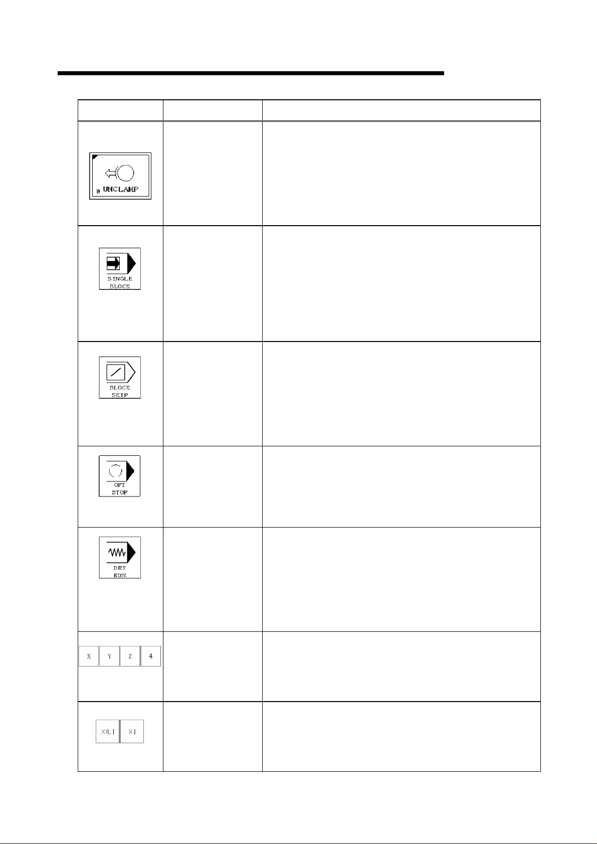
UNCLAMP
button, lamp
(White)
SINGLE
BLOCK
OPT
DRY RUN
X, Y, Z, 4-axis (axis
select)
BLOCK
button, lamp
(Green)
SKIP
button, lamp
(Green)
STOP
button, lamp
(Green)
button, lamp
(Green)
button, lamp
(Green)
Fun
ctio
n &Descr
This button is used for removing a tool from the spindle.
•E
It becomes effective, when the lamp of "HANDLE", "JOG",
"RAPID" or, and "REF" is on and "ASSIST" button is
pushed.
ø
If the button is pressed, the spindle will be unclamped and
air will be come out.
ø
When demounting a tool from a spindle, before pressing
the button, the tool is clamped certainly. When a
clamping is inadequate, the tool falls.
This button SINGLE BLOCK makes a block stop at
MEMORY, TAPE and/or MDI operations.
•E When the SINGLE BLOCK lamp turns on, and the butto
[CYCLE START] is pressed, the specified block is
executed and the cycle stops.
•E When the SINGLE BLOCK lamp turns off, and the butto
[CYCLE START] is pressed, the rest of the program is
executed accordingly.
•E When the SINGLE BLOCK button is pressed, the lam
turns on or off.
This BLOCK SKIP button is used to disregard the block,
when command line starts with / (slash), is MEMORY, TAPE
and/or MDI operation.
ø
When the BLOCK SKIP lamp turns on, the block with /
(slash) is neglected.
ø
When the BLOCK SKIP lamp turns off, the block with /
(slash) is executed.
ø
When the BLOCK SKIP button is pressed, this lamp turns
on or off.
This button is used to stop at the block of ?M01 signal in the
MEMORY, TAPE or MDI operation.
ø
When the lamp is lit, the operation stops at the block of
?M01 signal
ø
When the lamp is not lit, the operation stops at the block of
?M01 signal
ø
When pressing the button, this lamp is lit or not lit.
This DRY RUN button is used to move a feed unit with JOG
speed instead of cutting speed in MEMORY, TAPE and/or
MDI operation.
ø
When the DRY RUN lamp turns on, the feed unit moves
with JOG speed instead of cutting speed.
ø
When the DRY RUN lamp turns off, the feed unit moves
with cutting speed.
ø
When the DRY RUN button is pressed, the lamp turns on
or off.
This button is used to choosing JOG, RAPID FEED, ZERO
RETURN, and MOVE AXIS.
ø
The axis which the lamp has turned on is effective.
.
.
iption
X0.1,
X1
button, lamp
(White)
This button is used to changes the magnification of the
maximum speed (10000mm/min) of JOG feed.
ø
When JOG OVERRIDE is 100%
X0.1 •E•E•E•E•E 1000m
X1 •E•E•E•E•E 10000m
2-11
Page 31

2. MACHINE OUTLINE
Na
me Functio
AXI
S DIRECTION
button, lamp
FEED
ASSIST
button, lamp
(Green)
(Green)
FH
550SX/
n &Description
These buttons can indicate the direction of movement in
JOG, RAPID FEED, ZERO RETURN, MOVE DIRECTION.
•E When this button is pressed, axial feed is executed
It is a button for confirming the button of "+" and "-" at the
time of an axial move of JOG, RAPID FEED and ZERO
RETURN.
The button of "+" and "-" is pushed, pushing this button.
630
SX
MEMORY
DND
MDI
EDIT
HANDLE
JOG
button, lamp
(Green)
button, lamp
(Green)
button, lamp
(Green)
button, lamp
(Green)
button, lamp
(Green)
button, lamp
(Green)
This button is used to run the machine with the program, that
has been registed in memory storage of NC device.
•E After pushing this button, the lamp turns on, or off
This button is use to run from an external instrument.
•E After pushing this button, the lamp turns on, or off
This button is used to run the machine with the program, that
may be simple program through MDI.
•E After pushing this button, the lamp turns on, or off
This button is used to edit program operating with memory
(registered program in the NC unit).
•E After pushing this button, the lamp turns on, or off
This button is used to make axial traverse with handle
(manual pulse generator).
•E After pushing this button, the lamp turns on, or off
This button is used to make axial traverse with jog (speed
can be preset separately).
•E After pushing this button, the lamp turns on, or off
RAPID
button, lamp
(Green)
This button is used to make axial traverse in rapid feed
speed.
•E After pushing this button, the lamp turns on, or off
2-12
Page 32

2. MACHINE OUTLINE
FH
550SX/
630
SX
Name
REF
button, lamp
MODE ASIST
button, lamp
AUTO
button, lamp
WINDOW
button, lamp
(Green)
(Green)
(Green)
(Green)
Functio
This button is used to make each axis go back to its origin.
•E After pushing this button, the lamp turns on, or off
This is a button for changing the mode of MEMORY, DNC,
MDI, EDIT, HANDLE, JOG, RAPID FEED and ZERO
RETURN.
•E The button to choose is pushed, pushing this button
This button makes a continuous cycle to prepare, to
finishloading, to transport a pallet into the M/C, to machine
workpieces, and to transport a pallet.
•E When this button is pressed, the lamp turns on or turns off
When this button is flashing and the button of [CYCLE
START] is pressed.
This button is used to display the panel displaying WINDOW.
(Each lamp, function switch)
n &Descr
iption
ALARM
COOLANT
COOLANT ON
COOLANT
RESET
AUTO
button, lamp
OFF
button, lamp
button
(Green)
button
(Green)
(Green)
(Green)
This button is used to reset mechanical alarms without NC
alarm.
•E When this button is pressed, the alarm is released
This button is used to dispense (discharge) coolant (cutting
lubricant) from the coolant nozzle and chip throuwer when
M08/M12/M14 are commanded during memory operation,
tape operation and MDI operation.
•E When this button is depressed, coolant is discharged
•E When this button is depressed, the lamp lights up
This button is used to discharge coolant from the coolant
nozzle and
•E When this button is depressed, coolant is discharged
•E When this button is depressed, the lamp lights up
This button is used to stop coolant.
•E When this button is depressed, coolant stops
•E When this button is depressed, the lamp lights up
the chip flowing nozzle.
2-13
Page 33

2. MACHINE OUTLINE
Name Function & Description
FH
550SX/
630
SX
PALLET FORCE
UNLOADING
button, lamp
(Green)
(option)
MIST COLLECTOR
button, lamp
(Green)
AIR BLOW
button, lamp
(Green)
AUTO POWER OFF
button, lamp
(Green)
CHIP CONVEYER
button, lamp
(Green)
LIGHT
button, lamp
(Green)
This switch is used to unload forcebly the pallet.
This button is used to start the mist collector.
•E When t hi s butt on i s pr essed, t he l a mp will li ght up and t he
mist collector will start. (In the case of "coolant ON" while
memory and DNC are working, it becomes valid.)
•E When t he butt on i s pr essed agai n, a l a mp will t ur n off and
stop.
This button is used to make the air blow breathe out.
•E When t hi s butt on i s pr essed, t he l a mp will li ght up and t he
air blow will be breathed out.
•E When t he butt on i s pr essed agai n, a l a mp will t ur n off and
the air blow will stop.
This switch is used to intercept the main power source about
10 seconds after completing a machining. (It becomes valid
in the working of memory and DNC or at the working of
memory and DNC after pressing the button.)
•E M30 or M02 ar e read duri ng a dri vi ng, and when t he l a mp
of the {NEXT CYCLE START} button of pallet changer
operation panel is not on, the main power source
intercepts about 10 seconds after.
ø When thef
will
stop
This button is used to start the chip conveyer.
•E When t hi s butt on i s pr essed, t he l a mp will li ght up and t he
chip conveyer will rotate.
•E When t he butt on i s pr essed agai n, a l a mp will t ur n off and
stop.
This switch is used to be executed lighting ON/OFF.
aultoccursdu
ring the drivi
ng,PUMP
ON
SPDL ASSIST
button, lamp
SPDL CW
button, lamp
(Green)
(Green)
This button is used to be confirming a start up of the spindle.
The [CYCLE START] button is pushed, pushing this button.
This button is used for normal rotation of spindle.
•E When t he l a mp <HANDLE>, <J OG>, <RAPI D> or <REF>
in the operation mode is lighting, this button becomes
effective. In addition, this button is pressed, pressing
[ASSIST] button.
•E When t hi s butt on i s depr essed, t he spi ndl e r ot at es
normally.
•E When t hi s butt on i s depr essed, t he l a mp li ght s up.
2-14
Page 34

2. MACHINE OUTLINE
FH
550SX/
630
SX
CYCLE
FEED
DOO
DOOR
Name
START
button, lamp
HOLD
button, lamp
R LOCK
UNLOCK
(Green)
(Yellow)
button
button
Functio
This button makes the start of MEMORY, TAPE and MDI
operation, and ZERO Return. And also restart of the cycle
after Feed Hold, M00, M01, Single block.
•E
When this button is pressed, the lamp turns on.
•E
When this lamp turns on, the cycle starts.
This button makes the unit feeding to stop in MEMORY,
TAPE, MDI operation and Zero Return.
•E
When the button is pressed, the lamp turns on.
•E
When this lamp turns on, the unit feeding is decelerated.
After M-S-T function are executed, the cycle stops as a
single block.
This button makes locking the electromagnetic lock type door
lock of the operator door.
•E
The operator door electromagnetic lock type door switch is
locked, and it becomes impossible to open a door, if a
button is pushed after shutting an operator door.
This button makes canceling the electromagnetic lock type
door lock of the operator door.
•E
When the lamp of {UNLOCK OK} is on, if a button is
pushed, an electromagnetic lock type door lock is
canceled and a door can be opened.
n &Descr
iption
OPERATION
1-2
key switch
OPERATION
1, 2-3
key switch
POWER
MODE
MODE
lamp
(White)
This switch makes changes the operation mode to 1 or 2.
(
2.4.4
?Explanation of operation mode?
This switch makes changes the operation mode to 3.
(
2.4.4
?Explanation of operation mode?
This lamp goes on when turning ON the handle of the
no-fuse breaker on the control cabinet.
)
)
2-15
Page 35

2. MACHINE OUTLINE
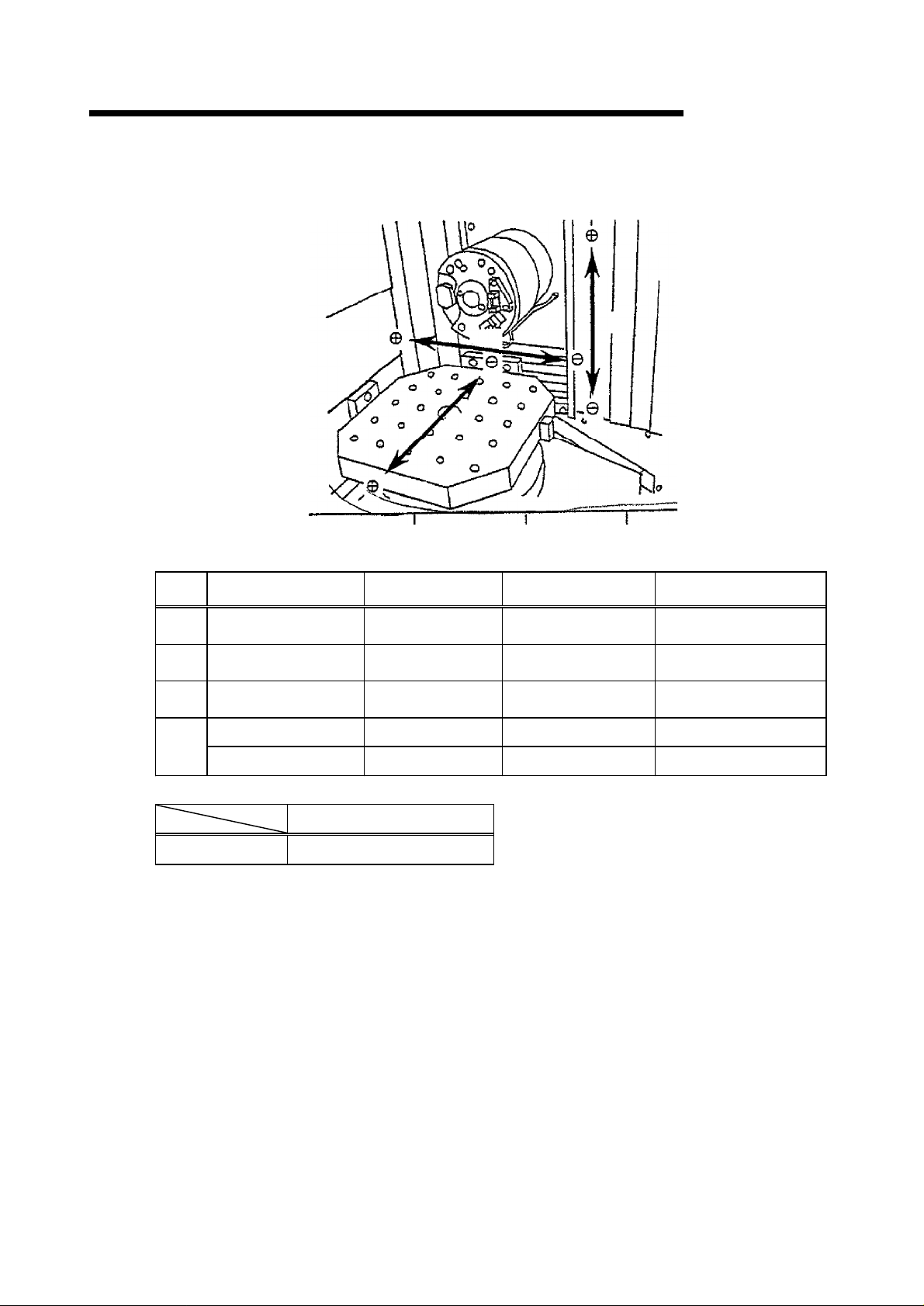
2.3.3 Handle Feed Operation Panel
FH
550SX/
630
SX
Name
Axis
Select
Selector switc
Feed
Multiply
Selector switch
Handle
(
Manual Pulse
Generator
Handle
)
Valid
button
(
Black
Function &Descri
This switch is used to select desired axis be moved
h
This switch is used to select the minimum increment ratio per
one division at the handle
•E
The minimum increment is designed as below
ø1 •E•E•E to ma0.001
ø
10
•E•E•E to ma0.01
ø
100
•E•E•E to ma0.1
ø For rotational axis, 0.
accordingly
(
Only NC table
This handle is used to make axial traverse
ø
Clockwise brings table to + direction, counterclockwise
brings table to ? direction, for the axis selected by [Axis
Select] at the feed speed preset by [Feed Multiply
•E This handle has
This button is used for opening a door and performing an
axial move by the handle
)
The axial move only of the time of feed multiply P1 and N
is carried out
•E When the deadman switch is pushe
•E When pushing a switc, it pushes on two phases. If it turns
on by the 1st time and it pushes still strongly, it will be
turned off and will not operate
.
)
100
.
.
mm movement per 1 div
mm movement per 1 div
mm movement per 1 div
001, 0.01 and 0.1
divisions around it
.
ption
.
:
.
.
.
is applied
.
].
.
.
10
2-
16
Page 36

2. MACHINE OUTLINE
2.3.4 Magazine Operation Panel
FH
550SX/
630
SX
2-
17
Page 37

2. MACHINE OUTLINE
Na
me F
MAGAZI
NE A
UTO
button
(Black)
FH
550SX/
unction& Description
This button is usedtochange to the Automatic mode.
øInordertorun in automa
øThetoolma
au
to.
gazinemay
tic
mode, press the button.
move any time, w
hen
630
sel
ectthe
SX
MAGAZI
MANUAL
MAGAZI
UNLO
CK
MAGAZI
LO
CK
CW
CCW
INCHING
NE
button
(Red)
NE D
OOR
button, lamp
(White)
NE D
OOR
button, lamp
(White)
button, lamp
(White)
button, lamp
(White)
button, lamp
(White)
Thisbuttonis used to change to th
øIn order to run in manualmode, press t
øThem
followingstate :
In automatic mode øøø TC & Toolmagazine are i
waiting
This buttonis usedto resettheinterlock of the magazi
door.
øIncase the lamp of <MAGAZINE UNLOCK OK> turn on,
lock can be reset.
øWhenpressingthis button, lock is resetandthelamp go
on
øWhenclosingthe d
LOCK] button, the lamp g
øWhenpressing the[MAGAZINE DOOR LOCK] buttonin t
state of impletion of doorclosing, the lamp blink.
Thisbuttonis used to interloc
Un
is not reset
Thisbutton is usedtomake Tool Magazine rotateCW.
øAfterpushing this button, the lamp blinkand Tool Magazine
rotates CW.
øIncase the lamp of [INCHING] turn on, Tool Magazine
rotatesCW
this button, Tool Magazine stops withdeceleration.
øWhen the lamp of [INCHING] turns off, Tool Magazine
rotates CW upon pushing this button
Thisbutton is usedtomake Tool Magazine rotateCCW.
øAfterpushing this button, the lamp blinkand Tool Magazine
rotates CCW
øIncase the lamp of [INCHING] turn on, Tool Magazine
rotatesCCW
de
dece
øWhen the lamp of [INCHING] turns off, Tool Magazine
rotatesCCWupon pu
This button is usedtomake Tool Magazine rotateinching
øAfter pushing thisbutton, the lamp turns on or off
øIncase the lamp turnson, the stateis magazine inching
øIncase the lamp turns off, the stateis magazine continuous
ach
ine can not
.
less closingthedoor and pressingthis button, therelease
.
during this buttonis pressed.
.
during
pressing this
leration.
run
oor a
nd pressingthe [MAGAZINE DOOR
oes
this button is pressed. Up
bu
tton, Tool Magazi
shing this button.
e Ma
nual mode.
he bu
tton.
in automatic mode with t
off.
k ofthe
magazinedoor.
Upon
depressi
.
ne
sto
.
ps
he
n
ne
es
he
ng
on
wit
.
.
h
.
2-
18
Page 38

2. MACHINE OUTLINE
Na
me Function &Descri
ption
FH
550SX/
630
SX
CW/CCW
EMERGENCY
TOOL
PREPARATION
ON/
ALARM
STOP
button, lamp
CHANGE
OFF
key switch
(
(
White
STOP
button
(
Red
Option
lamp
(
Red
This button is used to make Tool Magazine halt the rotation
ø
When the lamp of <INCHING> turns off and Tool
)
Magazine is rotating CW or CCW, Tool Magazine halts the
rotation with deceleration upon pushing this button
This button is used to shut off machine power and hydraulics
ø
After pushing this button, Machine Preparatory Circuits are
)
shut off, and all motions stop
ø
This button is locked at pressed state upon activation
ø
Turn to arrowed direction CW to be released
This switch is used to perform Tool Change or not
When Tool change is desired, select
When Tool change is not desired, select
ø
When this switch is selected for [ON] position, the
)
machine can not run in automatic mode with the following
state
:
In automatic mode •E•E•E A& Tool Magazine are in waiting
Out of automatic mode •E•E•E Forbidden to
In order to run in automatic mode, be selected for [OFF
position
When some faults occur, the lamp turns on
It?s blinks at the time of alarm
)
The lamp is turn off when fault or alarm status is canceled
.
.
[ON] position
[OFF] position
.
.
.
.
.
.
.
.
.
.
.
.
]
.
MANUAL
UNLOCK
CHANGE TL IN M
M/G
OK
(
OK
(
(
Orange
(
Option
OP.ALARM
(
Option
White
White
(
Changing to manual and when the manual operation is
lamp
possible, this lamp goes on
)
Changing to manual and when the magazine does not
lamp
activate, this lamp goes on
)
/G
In case the life time over tool or the broken tool is in the
lamp
magazine and replacement is necessary when DNC is
)
equipped, this lamp goes on
)
When the data fault is output from the OP supporter, this lamp
lamp
Red
goes on
)
)
.
.
.
.
2-
19
Page 39

2. MACHINE OUTLINE
2.3.5 Pallet Changer Operation Panel
FH
550SX/
630
SX
2-
20
Page 40

2. MACHINE OUTLINE
Na
me Function &Description
EMERGENCY
STOP
DOOR
UNLOCK
button, lamp
(
DOOR
LOCK
button, lamp
(
button
(
Red
White
White
FH
550SX/
This button is used to shut off machine power and hydraulics
•E After pushing this button, Machine Preparatory Circuits are
shut off, and all motions stop
)
•E This button is locked at pressed state upon activation
Turn to arrowed direction ?CW? to be released
This button is used to reset the interlock of the pallet changer
door
.
)
ø
In case the lamp of <UNLOCK OK> turn on, lock can be
reset
.
ø When pressing this button, lock is reset and the lamp goes
on
.
ø When closing the door and pressing the [DOOR LOCK
button, the lamp goes off
ø When pressing the [DOOR LOCK] button in the state of
impletion of door closing, the lamp blink
This button is used to interlock of the pallet changer door
Unless closing the door and pressing this button, the release is
)
not reset
.
.
.
.
.
.
.
630
]
SX
.
NEXT CYCLE
START
button, lamp
(
Green
CANCEL
(
Green
AUTO
(
Orange
ALARM
UNLOCK
OK
(
White
button
lamp
lamp
(
Red
lamp
This button is used to load workpieces at Pallet Changer Side
and to make a continuous machining operation
•E Upon pushing this button, the lamp turns on
)
workpiece has been machined, the pallet is changed
•E Upon pushing the button [CANCEL],
This button is used to cancel the loading finish
•E
Upon pushing this button, the lamp <NEXT CYCLE START
)
turns off
•E
When loading/unloading workpieces at Pallet Changer Side
push this button and confirm that the lamp <NEXT CYCLE
START> turns off, before you start to work
This button is used to turn the lamp [AUTO] on at Main
Operation Panel
)
This lamp turns on when some abnormal takes place
)
This lamp turns on when not operate the pallet changer
)
.
.
the lamp turns off
.
.
When the
.
.
.
.
,
.
.
>
,
2-
21
Page 41

2. MACHINE OUTLINE
2.3.6 Chip Conveyor Operation Panel
FH
550SX/
630
SX
2-
22
Page 42

2. MACHINE OUTLINE
Na
me Functi
on & De
scrip
tion
FH
550SX/
630
SX
EMERGENCY
AUTO
MANUAL
CW
button,
STOP
button
(
Red
button
(
Black
button
(
Red
lamp
(
White
This button is used to shut off machine power and hydraulics
•E After pushing this butto, Machine Preparatory Circuits are
)
shut off, and all motions stop
•E This button is locked at pressed state upon activatio
to arrowed direction CW to be released
This button is used to start Chip Conveyor in automatic mode
Normally keep this button [AUTO] being turn on
)
When the button [MANUAL] turns on, this button can be
used in inching mode
)
adjustment, cleaning etc
While this button is pushed, inching is done in CW
)
.
The inching mode is used for chain
.
.
.
.
.
.
.
Turn
.
CCW
MANUAL
ALARM
button,
(
OK
(
lamp
White
lamp
White
lamp
(
Red
While this button is pushed, inching is done in CCW
)
Press the [STOP] button and when the inching is possible
this lamp goes on
)
When some faults occur, the lamp goes on
)
.
.
.
,
2-
23
Page 43

2. MACHINE OUTLINE
2.3.7 Lamps
FH
550SX/
630
SX
Na
me
Abnorm
Running
Machining
al
Indicator (Red
Indicator (Orange
finish
Indicator (Green
Function &De
This lamp turns on, when the emergency stop
)
When any warning is informed, it makes flushing
This lamp turns on when the machine start
)
This lamp turns on when the operating or machined
)
workpiece is in the machine
scription
.
.
.
.
2-
24
Page 44

2. MACHINE OUTLINE
2.4 Door Interlock
FH
550SX/
630
SX
Door interlock comes in 3 types : operator?s door interlock, magazine door interlock
and pallet changer door interlock
Moreover, the operator?s door changes conditions with a operation changeover switch
(1, 2, 3
).
2.4.1 Operators Door Interlock
When the inside of a machining room has stopped and the <DOOR UNLOCK OK
lamp is on, if [DOOR UNLOCK] button is pushed,
can be opened
• EIf an operat or?s door i s opene, the lamp of <DOOR UNLOCK> of the main
operation panel lights up, and it will be in the status of
the midst of a tap cycle is stopped after a tap machining finish.
• EIf an oper at or?s door i s opene, it will be in the status of 1, 2, 3 of the operation
mode with the changeover switch of the main operation mode
tion of operation mode?
• EI n or der t o make it ret ur, the operator?s door is shut and the button of [DOOR
LOCK] in the main operation panel is pushed
locked and the lamp of <DOOR LOCK> puts out the light
,
.
>
an interlock is canceled and a door
.
2.4.4 term
)
.
The electromagnetic lock is
.
. (
2.4.4
.
However,
?Explana
-
2.4.2 Magazine Door Interlock
(1)
The conditions of a magazine door open
Stop of magazine operation
Stop of magazine indexing command
(2)
How to open the magazine door
Change the magazine f
Press the [MAGAZINE MANUAL]
Turn on the <MANUAL OK> or <UNLOCK OK> lamp
If the [MAGAZINE DOOR UNLOCK] button is pushed, an electromagnetic
lock is canceled and a door can be opened
The
mand
(3)
The power cutoff after opening a door
Power cutoff of magazine servo amplifier (Correlation voltage
Amplifier : 6AMP1 (
(4)
Return method
Close the door and press the [MAGAZINE DOOR LOCK
Press the [MAGAZINE AUTO] button
An electromagnetic lock is locked and a return becomes possible
When it returns in the order of not the above-mentioned order but [MAGA
ZINE AUTO],
pushed again and a return becomes possible by making it [MAGAZINE
AUTO
electro
magnetic
during magazine
and [MAGAZINE DOOR LOCK], [MAGAZINE MANUAL] is
].
rom
auto to manual
button
.
.
.
lock cannot be canceled when there is an indexing
indexing
between
.
6U1, 6V1, 6W1)
.
)
] button
.
.
com
-
-
2-
25
Page 45

2. MACHINE OUTLINE
2.4.3 Pallet Changer Door Interlock
(1)
Condition of the pallet changer door open
Stop of operation of pallet changer
No command of pallet changer up/down
No command of clamp/unclamp on pallet changer
(2)
How to open the pallet changer door
During stop of operation of pallet changer, when
on,
press the
is canceled and a door can be opened
(3)
The power cutoff after opening a door
Pallet clamp/unclamp and CW/CCW on the pallet changer
(1P
211
M-1N
Pallet changer master valve common cutoff
(1P
211
M-1N
[P/
C DOOR UNLOCK] button
212
Correlation voltage : 0V)
212
Correlation voltage : 0V)
FH
550SX/
[P/
C UNLOCK OK] lamp is
.
If button is pushed, an interlock
.
630
SX
(4)
Return method
Close the pallet changer door and press the
An electromagnetic lock is locked and a return becomes possible
Pallet changer operation becomes possible by pressing the [NEXT CYCLE
START
[P/
C DOOR LOCK] button
].
.
.
2-
26
Page 46

2. MACHINE OUTLINE
2.4.4 Explanation of Operation Mode
FH
550SX/
630
SX
OPERATION MODE
OPERATION MODE
Operator?s level
Mode switch
The conditions
which an operator
door can open
How to open the
operator?s door
NC condition
Power cutoff, etc
Return method
Setting of operation mode select switch
•E In case of set to operation mode
Operation mode switch Left
•E In case of set to operation mode
Operation mode switch Left
•E In case of set to operation mode
Operation mode switch Left
Mode
1
(
Auto cycle
Performs workpiece attach/detach
and a transfer
•E The oper ati on of t he machi ne i n a
machining room has stopped
•E Tur n on t he<DOOR UNLOCK OK
lamp
[DOOR UNLOCK] button is pushed
in the status that the inside of a
machining room has stopped
Emergency stop
•E Feed axi, Spindle, ATC, Magazine
servo cutoff
•E Hydraulic pump cutoff
•E Tabl e cl a m, unclamp, pallet clamp
unclamp cutoff
•E Tool cl a m, unclamp cutoff
•E Socket C, CCW cutoff
•E Pall et u, down, CW, CCW cutoff
•E ATC shutter cutoff
.
•E Air blow cutoff
•E Coolant cutoff
*
Machining continuation is
impossible
Close the operator?s door, and press
the [DOOR LOOK] button
And then turn on the PUMP ON
Execute the pallet change at MDI
After change the workpiece, perform
machining the next workpiece
)
Performs workpiece attach/detach
and a transfer + jig work centering
1 2 3
•E The oper ati on of t he machi ne i n a
.
>
•E Tur n on t he<DOOR UNLOCK OK
[DOOR UNLOCK] button is pushed
.
.
.
in the status that the inside of a
machining room has stopped
NC reset
Axis interlock (with sequence
•E ATC cutoff
•E Socket C, CCW cutoff
,
•E Pall et C, CCW cutoff
•E ATC shutter cutoff
•E Air blow cutoff
•E Coolant cutoff
*
*
*
*
Close the operator?s door, and press
the [DOOR LOOK] button
.
And then execute the pallet change
.
at MDI. And execute the workpiece
change
When execute the machining
change to mode 1. (At the door
open, change mode is turn to
emergency stop
(1)
: [1]
Right
: [1,
(2)
: [2]
Right
: [1,
(3)
: [1]
or [2]
Right
Mode
2
(
Setting
)
machining room has stopped
lamp
(
Master valve cutoff
(
Master valve cutoff
(
Master valve cutoff
Orient keep possible
Spindle rotation interlock by
sequence
Only the handle mode 1, ø
valid with the demand switch (
position demand switch
Machining continuation is
impossible
.
)
)
)
)
.
.
)
10
)
.
2]
2]
: [
3]
Mode
(
The option for manual adjust under
the restricted operate condition
Performs program debug and
maintenance
•E The oper ati on of t he machi ne i n a
machining room has stopped
>
•E Tur n on t he<DOOR UNLOCK OK
lamp
[DOOR UNLOCK] button is pushed
in the status that the inside of a
machining room has stopped
Axis interlock (with sequence
•E ATC cutoff
•E Socket C, CCW cutoff
(
Master valve cutoff
•E Pall et C, CCW cutoff
(
Master valve cutoff
•E ATC shutter cutoff
(
Master valve cutoff
•E Air blow cutoff
•E Coolant cutoff
*
Orient keep possible
*
Spindle rotation interlock by
sequence
are
*
Only the handle mode 1, ø
3
valid with the demand switch (
position demand switch
*
Series machining disabling
Close the operator?s door, and press
the [DOOR LOOK] button
And then press the [CYCLE START
button, execute the re-machining
When execute the continuous (
,
change operation), change the mode
to 1,
execute the machining
(At the door open, change mode is
turn to emergency stop
3
)
)
)
)
.
)
)
.
>
.
)
10
are
3
]
.
pallet
.
2-
27
Page 47

3. OPERATION METHOD
3.
1
From Power ON to Pump ON
3.1.
1
Before Turning Power ON
Before turning power on, check the oil level of each component unit, and air
pressure
*
Check to see if the oil level lies above [L]
gauge glass, above its center
tubular gauge glass, below is center),
(
for a tubular gauge glass, up to its center
*
Check whether the supply air pressure is 0.4
gauge. If it is too low, open the cock of the air supply. Again check whether the
supply air pressure has reached a proper pressure
FH
550SX/
.
on the level gauge (for a tubular
) .
If the oil level lies below or near [L
supply oil up to [H]
).
MPa •}0.05,
.
on the level gauge
with the pressure
630
] (
SX
for a
For details of lubricating points, oils, and such, refer to the maintenance manual
Air pressure
Oil air lubricating oil
Slide lubricating oil
Spindle coolant
.
3-1
Working oil
Page 48

3. OPERATION METHOD
3.1.2 For Bringing the Machine into Operable Condition
3.1.2.1 For Turning on the Main Power
Power lamp
Circuit breaker
Turn the lever of the circuit breaker on the door of the
control panel clockwise to
The <POWER> lamp on the door of the control panel
and <POWER> lamp on the main operation panel
should come on
FH
550SX/
[ON
].
.
630
SX
Control panel door
DANGER
High voltage
If you receive electric
shock, you may suffer
serious damage, resulting
in death
Prior to maintenance or in
spection, never fail to turn
power off
:
.
.
!
-
3-2
Page 49

3. OPERATION METHOD
3.1.2.2 For the Turning on the NC Power
FH
550SX/
630
SX
Press the [|
main operation panel
The NC unit should start and show the current value
screen on the NC panel display located on the main
operation panel
NC ON] pushbutton on the NC panel of the
.
.
<NOTE>
*
The NC unit takes about
the ROM, system, etc
10
seconds to start. This is because the NC unit checks
.
3-3
Page 50

3. OPERATION METHOD
3.1.
3
Pump On
3.1.3.
1
For Turning on the Pump On Function
FH
550SX/
630
SX
EMERGENCY STOP
(1) Turn the [EMERGENCY STOP] pushbutton clockwise to
release its locked state
The [EMERGENCY STOP] pushbutton is installed on
main operation panel, magazine operation panel
chip conveyor operation panel , pallet changer
operation panel and
Release all those [EMERGENCY STOP] pushbuttons
from the locked state
.
handle feed operation panel
.
,
.
3-4
Page 51

3. OPERATION METHOD
FH
550SX/
630
SX
<NOTE>
<IMPORTANT>
(2) Press the [PUMP ON] pushbutton on the main operation panel
The lamp built in the <PUMP ON> pushbutton
Each of the following units operates to bring the machine in oper
able condition
*
Hydraulic oil pump
*
Lubricating oil pump
*
Spindle cooling unit
*
Servo unit on
*
Supply air pressure valve on
Before running the machine, make sure that no person is present within the
operating range of the machine such as the vicinity of the magazine
In turning on the operation preparation function, hold the [EMERGENCY
STOP] pushbutton lightly so that you can press it as soon as an abnormality
occurs in the machine.
.
.
.
.
-
3-5
Page 52

3. OPERATION METHOD
3.1.3.
2
After Turning on the PUMP ON Function
After turning on the control on function, be sure to check the following hydraulic
units for pressure
FH
550SX/
.
630
SX
Air pressure
Oil-air lubricating oil
Slide lubricating oil
Spindle coolant
Working oil
(0.4 MPa •}0.05
(0.
(5.5 MPa •}
(1.6 MPa
(2.7 MPa
29
MPa or less
0.2)
)
)
)
)
3-6
Page 53

3. OPERATION METHOD
3.
2
Stopping the Machine
3.2.
1
For Stopping the Machine in an Emergency
FH
550SX/
630
SX
It is sometimes necessary to stop the machine immediately during its operation
such a case, stop it by the following procedure
EMERGENCY STOP
.
In
.
Press the [EMERGENCY STOP] pushbutton
The [EMERGENCY STOP] pushbutton is installed on
main operation panel, magazine operation panel
chip conveyor operation panel and
operation panel and
The lamp built in the <PUMP ON> pushbutton should go
out; the controlled axes and spindle in operation should slow
down and then stop; and the operation of all the units should
stop
.
handle feed operation panel
pallet changer
.
,
.
3-7
Page 54

3. OPERATION METHOD
FH
550SX/
630
SX
<NOTE>
<NOTE>
If you press the [EMERGENCY STOP] pushbutton when the spindle is running, the
?SPINDLE RUN ALARM? is given but this is not a problem. To release this alarm
reset the [EMERGENCY STOP] pushbutton, and after pressing the [PUMP ON
pushbutton on the main operation panel, press the [RESET] key of the NC panel
In the case when you press the [EMERGENCY STOP] pushbutton during the tool
change operation, reset the [EMERGENCY STOP] pushbutton, and after pressing
the [PUMP ON] pushbutton on the main operation panel, execute the M
change) command by MDI
continue
In the case when you press the [EMERGENCY STOP] push button during the pallet
changing operation,
ing the [PUMP ON] pushbutton on the main operation panel, execute the M
let change) command by MDI
not continue
.
.
.
However, if you ran the machine, tool change does not
reset the [EMERGENCY STOP] push button, and after press
.
However, if you ran the machine, tool change does
,
]
.
06 (tool
90 (pal
-
-
3-8
Page 55

3. OPERATION METHOD
3.2.
2
Stopping the Operation at the End of Work
3.2.2.
1
For Stopping the Machine
FH
550SX/
630
SX
EMERGENCY STOP
Press the [EMERGENCY STOP] pushbutton
The EMERGENCY STOP pushbutton is installed on
operation panel, magazine operation panel, Chip conveyor
operation panel, pallet changer operation panel and
feed operation panel
The lamp built in the <PUMP ON> pushbutton should go off
.
.
main
handle
.
3-9
Page 56

3. OPERATION METHOD
FH
550SX/
630
SX
3.2.3 For Stopping the Machine during Memory-,
Tape-, and MDI-mode Operation
3.2.3.1 For Stopping the Machine by NC Resetting
Press the [RESET] key on the NC panel of the main
operation panel
The program should be reset and the controlled axes
and spindle in operation should slow down and then
stop
.
To restart the operation, search for the program and
accomplish the origin return operation
3.2.3.2 For Stopping the Machine by Single Block Operation
Press the [SINGLE BLOCK] key on the main operation panel
.
.
.
<NOTE>
The lamp built in the <SINGLE BLOCK> pushbutton
should light up and the machine should stop after the
block under execution is completed
To restart the operation, press the [CYCLE START
pushbutton again
block. At this time, while the lamp in the <SINGLE
BLOCK> pushbutton is lit, the machine should stop each
time one block is executed
In the following cases, the machine stops after the cycle advanced to the
position where it can stop
*
When a cycle such as a fixed cycle is in progress
cycles at which block the single block operation is accepted. Refer to the item
of each cycle in the programming manual
*
When the control variable for nullifying the single block operation is set in the
custom macro
variable is cleared
.
At this time, the machine stops at the block where that control
.
.
.
The operation should start with the next
.
.
.
]
.
At this time, it depends on
3-
10
Page 57

3. OPERATION METHOD
3.2.3.3 For Stopping the Machine by Pausing
Press the [FEED HOLD] pushbutton on the main operation panel.
The lamp built in the <FEED HOLD> pushbutton should light up, and
the controlled axes in operation should slow down and then stop.
At this time, the spindle does not stop.
(3.6.3.1 gFor st oppi ng t he spi ndl e manuall )
To restart the operation, press the [CYCLE START] pushbutton. Then
the operation should restart.
FH
550SX/
630
SX
<NOTE>
In the following cases, the machine stops after the cycle advanced to the position
where it can stop.
* When the cutting feed operation is in progress in the tapping cycle, a fixed cycle. At
this time, the machine stops after tapping has been completed and the controlled
axes have returned to R point or their initial points.
* When the control variable for nullifying the feed hold operation is set in the custom
macro. At this time, the machine stops immediately after the block where that
control variable has been cleared is started.
* In case of thread cutting, the machine stops right after a future block other than the
thread cutting block is started.
3.2.3.4 For Stopping the Machine by Mode Change
When you switches the operation mode select pushbutton on the main operation
panel, the controlled axes in operation should slow down and then stop. The resultant operation of the control unit, which varies depending on a mode to be newly
selected, is as follows.
Newly-selected mode Resultant operation of control unit
Memory, tape, MDI
Handle, jogging, rapid
feed, zero return
Until the block under execution will
be completed, the machine
continues and then stops.
Afterward, the machine operates
in a new mode.
The machine stops at once, and
then operates in a new mode.
3-11
Page 58

3. OPERATION METHOD
3.2.3.5 For stopping the machine by cutting feed override
Set the {CUTTING FEED} override select switch on the main
operation panel to [0].
The controlled axes in operation should slow down and then
stop. If this override switch is set to
tion as well as the cutting feed operation should stop
FH
550SX/
[0], the rapid feed opera
630
.
SX
-
<NOTE>
In the following cases, the override select switch is nullified
*
During cutting by the tapping cycle, or a fixed cycle
*
During thread cutting
*
When the control variable for nullifying cutting feed override (#3004=2, 3, 6, 7)
set in the custom macro
.
.
is
3-
12
Page 59

3. OPERATION METHOD
3.3Turning Off the Power
3.3.1 ForTurning Off the NC Power
FH
550SX/
Press the [ NC OFF ] pushbutton on the main operation
panel
.
630
SX
ø
<IMPORTANT>
Do not turn off the power during program editing. When the power is
turned off during editing , data may be erased. If the power is turned
off, check the storage for contents.
3.3.2 ForTurning Off the Main Power
Power lamp
The CNC screen indication should disappear
Turn the lever of the circuit breaker on the control panel
door counterclockwise to [OFF
].
.
Control panel door
Circuit breaker
The <POWER> lamp on the main operation panel and
the <POWER> lamp on the control panel should goes
out
.
3-
13
Page 60

3. OPERATION METHOD
3.4 Origin Return Operation
3.4.1 For Returning All Axes to their Origins
(1) [
(2)
FH
550SX/
REF] button is pressed, pressing the
ASSIST] pushbutton on the main operation panel
The lamp built in the <REF> pushbutton should
come on
Press the [CYCLE START] pushbutton on the main
operation panel
.
.
630
[MODE
SX
.
*
First, the Z axis return to its home position; next, the
X and Y axes, in this order, return to their
respective home position; then, the B axis returns
to its home position
*
During the origin return cycle
pushbutton lamp is lit
*
In case of all-axis
FEED} override select switch on the main operation
panel is enabled
*
Press the [WINDOW] pushbutton on the main opera
tion panel. And touch the [LAMP] on the NC screen
top.
Display the each axis lamp
*
When the axes return to their respective
sitions, their <ZERO POSITION> lamps light up in
order of completion
.
, the <CYCLE START
.
zero
return
.
.
speed
.
, the {RAPID
home po
>
-
-
<NOTE>
<NOTE>
If the {RAPID FEED} override select switch on the main operation panel is set
to
[0], zero return is not performed
All-axis zero return is accomplished by the custom macro program. When the
<
SINGLE BLOCK> pushbutton lamp is lit, the cycle is executed block by
block
.
3-
14
.
Page 61

3. OPERATION METHOD
3.4.2 Each Axis Origin Return
FH
550SX/
(1) [
REF] button is pressed, pressing the [MODE AS
SIST] pushbutton on the main operation panel
The lamp built in the <REF> pushbutton should come
on
.
630
.
SX
-
(2)
Select the axis select button
need to zero return on the main operation panel
(3)
Continue pressing the feed direction
until the origin lamp will light up, pressing [FEED AS
SIST] pushbutton in the main operation panel
*
In case of
ride select switch on the main operation panel is
enabled
*
Press the [WINDOW] pushbutton on the main op
eration panel. And touch the [
screen top
When the <ZERO POSITION> lamp comes on, origin
return of the selected axis is complete
zero
return
.
.
Display the manual lamp
[X], [Y], [Z], [4], what you
[+]
or [] pushbutton
speed, the RAPID FEED
LAMP
] on the NC
.
.
.
-
.
over
-
-
3-
15
Page 62

3. OPERATION METHOD
3.4.3 For Performing Zero Return in MDI Mode
(1) [
FH
550SX/
MDI] button is pressed, pressing the [MODE
ASSIST] pushbutton on the main operation panel
The lamp built in the <MDI> pushbutton should
come on
.
630
SX
.
(2)
Press the menu key [PROG] on the NC panel of the
main operation panel
The program screen is displayed
(3)
Press the menu key [PROG] on the
the main operation panel
The MDI screen is displayed
.
.
LCD
.
.
screen of
3-
16
Page 63

3. OPERATION METHOD
FH
550SX/
(4)
Press the alphabet, number and other keys on the
NC panel of the main operation panel in the order of
[G], [9], [1], [G], [2], [8], [X], [0], [Y], [0], [Z], [0],
[
EOB
], [M], [1], [1], [
[
EOB],
The data entry field will show ?G91G28X0Y0Z0;
M11; G28B0; M10
[M], [1], [O], and [EOB
;?
EOB
], [G], [2], [8], [B], [0],
].
630
SX
:
3-
17
Page 64

3. OPERATION METHOD
FH
550SX/
(5)
Press the menu key [INSERT] on the NC panel of
the main operation panel
.
630
SX
The data display field will show the program
.
<NOTE>
(6)
Press the [CYCLE START] pushbutton on the main
operation panel
The <CYCLE START> pushbutton lamp goes on, and
the program should be executed. First, the X, Y
Z axes return to their own home positions at the same
time. Next, the table is unclamped; the B axis returns to its home position; and the table is clamped
Depending on programs, the axes can be returned to their respective home
positions in certain order
The B axis does not rotate unless the table is not unclamped by M11.
.
.
, and
.
3-
18
Page 65

3. OPERATION METHOD
3.5 Feed Operation
3.5.1 Handle Feed
FH
550SX/
(1) [
HANDLE] button is pressed, pressing the [MODE
ASSIST] pushbutton on the main operation panel
The lamp built in the <HANDLE> pushbutton should
come on
(2)
Set the {AXIS SELECT} selection switch on the handle
feed operation panel to a desired position
*
*
.
.
The 4-axis represents the B axis, on which the
table rotates
upward in the MDI mode and then select
with the NC table, the table unclamp is turned on if
the table is selected
The 5-axis represents an optional axis
.
For the 1 deg. table, move the table
.
.
.
630
SX
.
Besides
,
(3)
Select travel per scale of the handle with the {MULTI
PLY} select switch on the handle feed operation panel
Travel per scale of the handle can be changed by
magnification
X, Y, Zø1 •E•E0.001
ø
10
•E•E0.010
ø
100
•E•E0.100
B-
axis (NC table
ø1 •E•E0.001
ø
10
•E•E0.01
ø
100
•E•E
(4)
Turn the [HANDLE] on the handle feed operation panel
in the direction in which you wish to turn. While you
turn the handle, the selected axis should travel
When traveling to the
comes into overtravel and slows down and then
stops. Then the alarm is given
axis
0.1ø
mm
ø
ø
.
mm
mm
)
end or
.
end
, the axis
.
.
3-
19
Page 66

3. OPERATION METHOD
3.5.2 Jog Feed
FH
550SX/
(1) [
JOG] button is pressed, pressing the [MODE AS
SIST] pushbutton on the main operation panel
The lamp built in the <JOG> pushbutton should come
on
.
630
.
SX
-
(2)
Set the {JOG FEEDRATE} selection switch and X
X1 of JOG on the main operation panel at a desired
feedrate
Use the X
Travel speed can be set in 0 ~
And when set the [JOG FEEDRATE] to
[X1], it clamped to
(3)
Select a fed axis with the {JOG ASSIST} selection switch
on the main operation panel
.
0.1, X1 buttons for selection of X
10000 mm/
1000 mm/
The 4-axis represents the B axis, on which the table
rotates
.
min
.
.
0.1, X1.
min
110% by
0.1,
.
(4) [+]
or
[-]
button is pressed,
ASSIST] pushbutton on the main operation panel
While you press the handle, the <+>
lamp should light up and the selected axis should travel
When you release the pushbutton, the axis should stop
When traveling to the
comes into overtravel and slows down and then
stops. Then the alarm is given
3-
20
pressing the [FEED
or <->
end or
end
, the axis
.
pushbutton
.
.
.
Page 67

3. OPERATION METHOD
3.5.3 Rapid Feed
FH
550SX/
(1) [
RAPID] button is pressed, pressing the [MODE
ASSIST] pushbutton on the main operation panel
The lamp built in the <RAPID> pushbutton should
come on
.
630
SX
.
(2)
Set the {RAPID FEED} override selection switch on the
main operation panel at a desired feedrate
Travel speed can be set in 6 steps
10%,50%,100
(3)
Select a feed axis with press the
button on the main operation panel
Turn on the selected button lamp
(4) [+]
or
[-]
ASSIST] pushbutton on the main operation panel
%).
button is pressed,
[X], [Y], [Z], [4] select
.
.
pressing the [FEED
.
(0%,1%, 5%,
.
While you press the handle, the <+>
lamp should light up and the selected axis should travel
When you release the pushbutton, the axis should stop
When traveling to the
comes into overtravel and slows down and then
stops. Then the alarm is given
3-
21
end or
or <->
pushbutton
end
, the axis
.
.
.
Page 68

3. OPERATION METHOD
3.5.4Turning Operation ofTable
FH
550SX/
(1) [
MDI] button is pressed, pressing the [MODE
ASSIST] pushbutton on the main operation panel
The lamp built in the <MDI> pushbutton should
come on
.
630
SX
.
(2)
Press the menu key [PROG] on the NC panel of the
main operation panel
.
3-
22
Page 69

3. OPERATION METHOD
FH
550SX/
(3)
With alphabetic keys, numeric keys, and other keys
on the NC panel of the main operation panel, input a
program
(
Example) To turn the table clockwise by
press keys as
[0], [0], [B], [9], [0], [.], [
[
EOB
].
.
90
[M], [1], [1], [
?
EOB],
[G], [9], [1], [G],
EOB
], [M], [1], [0],
630
SX
degrees
and
,
The data entry field will shown ?M11; G91
M10;?.
For the 1-deg. table, command in 1-degree incre
ments, respectively
To turn the table clockwise by
mand as ?B90.
degrees, command as ?B-45
.
90
degrees, com
? To turn it counterclockwise by
.?
GOOB90.;
45
-
-
3-
23
Page 70

3. OPERATION METHOD
FH
550SX/
(4)
Press the menu key [INSERT] on the NC panel of
the main operation panel
.
630
SX
The program is displayed in the data display field
.
<NOTE>
(5)
Press the [CYCLE START] pushbutton on the main
operation panel
The <CYCLE START> pushbutton lamp goes on
and the table should move up and the B axis
should rotate
should move down
• EIf t he co mmand wit h t he bad t abl e r ot ati on co mmand of under t he val ue of t he mi .
moves etc. come out, the alarm of the ?Swivel table index angle inconsistence? will
come out
• E When t he t ool change(M06)
formed to the same block, in M
and M10,
.
and it operates
and table unclamp (M11
06
and M11, M11
.
.
.
After the B axis stops, the table
.
) /
table clamp (M10) are per
has priority, M
06
has priority in M
,
06
3-
24
Page 71

3. OPERATION METHOD
3.6 Spindle Rotating Operation
3.6.1 Setting of Spindle Speed
FH
550SX/
Before rotating the spindle, you must specify the
spindle speed
(1) [
MDI] button is pressed, pressing the [MODE
ASSIST] pushbutton on the main operation panel
The lamp built in the <MDI> pushbutton should
come on
. T
o set it, follow the procedure belo
.
630
SX
w.
.
(2) Press the [
main
The program screen is displayed
(3) Press the menu key [
of the main operation panel.
The MDI screen is displayed
PROG
operation panel
] key on the NC panel of the
.
PROG
.
] on the
.
LCD
screen
3-
25
Page 72

3. OPERATION METHOD
FH
550SX/
(4)
With alphabetic keys, numeric keys, and other keys
of the NC panel on the main operation panel, input a pro
The spindle speed should be within the range
shown in the table below
Standard
When the S command out of the spindle speed
range is issued, the ?S CODE ALARM? will be
issued
.
gram
.
.
Spindle speed
35
~6,
000
min
630
-1
SX
(
Example
To set the spindle speed at
as
?S
500;? will be displayed in the data entry area
(5)
Press the menu key [INSERT] on the NC panel of
the main operation panel
The program will be displayed in the data display
)
[S],[5],[0],[0], and [EOB
.
500
].
min-1,
press keys
.
.
3-
26
Page 73

3. OPERATION METHOD
(6)
Press the [CYCLE S
operation panel
FH
550SX/
TART] pushbutton on the main
.
630
SX
The lamp built in the <CYCLE S
lights up, the program is executed, and the S
command is set
T
o make sure that the S command has been set
use the following procedure
Press the menu key [
screen of the
The check screen is displayed
Check the ?S
.
main operation panel
? value on the screen
TART> pushbutton
.
CHECK
] on the LCD
.
.
.
,
3-
27
Page 74

3. OPERATION METHOD
3.6.2 Spindle Rotating Operation
3.6.2.1 For Rotating the Spindle Clock Wise Manually
FH
550SX/
630
SX
(1) Pressed one of the pushbuttons, [
[
RAPID], and
on the main operation panel
The pressed pushbutton lamp will be lit
(2) [
SPDL CW] button is pressed, pressing the [SPDL
ASSIST] pushbutton on the main operation panel
The <SPDL CW> pushbutton lamp
the spindle clock wise at the rotational speed preset by
the S command
[REF], pressing [MODE ASSIST] button
.
.
HANDLE
.
will be lit, rotating
], [
JOG
.
],
To make sure that the S command has been set
use the following procedure
Press the menu key [
screen of the
The check screen is displayed
3-
28
main operation panel
.
CHEC
,
K] on the LCD
.
.
Page 75

3. OPERATION METHOD
FH
550SX/
630
SX
<NOTE>
Check the ?
When the spindle speed is not set, the ?NO S CODE COMMAND? alarm is
issued
.
(
3.6.1
?Setting of Spindle Speed?
)
S
? value on the screen
.
<NOTE>
The spindle speed can be changed in the range from
{
SPINDLE} override selection switch
When the spindle speed is max.,
speed by the override switch
When the spindle speed is min.,
speed by the override switch
.
.
.
the speed is fixed to max. even if up the
the speed is fixed to min.even if down the
50
to
150% with the
3-
29
Page 76

3. OPERATION METHOD
3.6.2.2 For Rotating the Spindle Clockwise in MDI Mode
(1) [
MDI] button is pressed, pressing the [MODE
ASSIST] pushbutton on the main operation panel
The lamp built in the <MDI> pushbutton should
come on
FH
550SX/
.
630
SX
.
(2) Press the key [
main
operation panel
The program screen is displayed
PROG
.
] on the NC panel of the
.
3-
30
Page 77

3. OPERATION METHOD
FH
550SX/
(3)
Using the letter and number keys on the NC panel
of the main operation panel, press
?M03;
? is displayed in the data entry area
: [M] [0] [3] [
630
.
SX
EOB
].
(4)
Press the menu key [INSERT] on the NC panel of
the main operation panel
The program is displayed in the data display area
.
.
3-
31
Page 78

3. OPERATION METHOD
FH
550SX/
(5)
Press the [CYCLE START] pushbutton on the main
operation panel
.
630
SX
The <CYCLE START> pushbutton lamp is lit, rotat
ing the spindle forward at the rotational speed preset
by the S command
.
-
3-
32
Page 79

3. OPERATION METHOD
FH
550SX/
630
SX
To make sure that the S command has been set
use the following procedure
Press the menu key [
screen of the
The check screen is displayed
Check the ?S
main operation panel
.
CHEC
K] on the LCD
.
.
? value on the screen
.
,
<NOTE>
<NOTE>
When the spindle speed is not set, the ?NO S CODE COMMAND? alarm is
issued
.
(
3.6.1
?Setting of Spindle Speed?
The spindle speed can be changed in the range from
{
SPINDLE} override selection switch
When the spindle speed is max.,
speed by the override switch
When the spindle speed is min.,
speed by the override switch
)
50
to
150% with the
.
the speed is fixed to max. even if up the
.
the speed is fixed to min.even if down the
.
3-
33
Page 80

3. OPERATION METHOD
3.6.2.3 For Rotating the Spindle Counterclockwise in MDI Mode
(1) [
MDI] button is pressed, pressing the [MODE
ASSIST] pushbutton on the main operation panel
The lamp built in the <MDI> pushbutton should
come on
.
FH
550SX/
630
SX
.
(2) Press the key [
main
operation panel
The program screen is displayed
PROG
.
] on the NC panel of the
.
3-
34
Page 81

3. OPERATION METHOD
FH
550SX/
(3)
Using the letter and number keys on the NC panel
of the main operation panel, press
?M04;
? is displayed in the data entry area
: [M] [0] [4] [
630
.
SX
EOB
].
3-
35
Page 82

3. OPERATION METHOD
FH
550SX/
(4)
Press the menu key [INSERT] on the NC panel of
the main operation panel
.
630
SX
The program is displayed in the data display area
.
(5)
Press the [CYCLE START] pushbutton on the main
operation panel
The <CYCLE START> pushbutton lamp is lit, rotat
ing the spindle counterclockwise at the roational
speed preset by the S command
.
.
-
3-
36
Page 83

3. OPERATION METHOD
FH
550SX/
630
SX
To make sure that the S command has been set
use the following procedure
Press the menu key [
screen of the
The check screen is displayed
Check the ?S
main operation panel
.
CHEC
K] on the LCD
.
.
? value on the screen
.
,
<NOTE>
<NOTE>
When the spindle speed is not set, the ?NO S CODE COMMAND? alarm is
issued
.
(
3.6.1
?Setting of Spindle Speed?
The spindle speed can be changed in the range from
{
SPINDLE} override selection switch
When the spindle speed is max.,
speed by the override switch
When the spindle speed is min.,
speed by the override switch
)
50
to
150% with the
.
the speed is fixed to max. even if up the
.
the speed is fixed to min.even if down the
.
3-
37
Page 84

3. OPERATION METHOD
3.6.3 Stopping the Spindle
3.6.3.1 For Stopping the Spindle Manually
FH
550SX/
630
SX
(1) Pressed one of the pushbuttons, [
[
RAPID], and
on the main operation panel
The pressed pushbutton lamp will be lit
(2)
Press the [SPDL STOP] pushbutton on the main opera
tion panel
The spindle will be stopped
[REF], pressing [MODE ASSIST] button
.
.
.
HANDLE
.
], [
JOG
],
-
3-
38
Page 85

3. OPERATION METHOD
3.6.3.2 For Stopping the Spindle in MDI Mode
FH
550SX/
(1) [
MDI] button is pressed, pressing the [MODE
ASSIST] pushbutton on the main operation panel
The lamp built in the <MDI> pushbutton should
come on
.
630
SX
.
(2) Press the key [
main
operation panel
The program screen is displayed
PROG
.
] on the NC panel of the
.
3-
39
Page 86

3. OPERATION METHOD
FH
550SX/
(3)
Using the letter and number keys on the NC panel
of the main operation panel, press
?M05;
? is displayed in the data entry area
: [M] [0] [5] [
630
.
SX
EOB
].
3-
40
Page 87

3. OPERATION METHOD
FH
550SX/
(4)
Press the menu key [INSERT] on the NC panel of
the main operation panel
.
630
SX
The program is displayed in the data display area
.
(5)
Press the [CYCLE START] pushbutton on the main
operation panel
The <CYCLE START> pushbutton lamp is lit
spindle will be stopped
.
.
, and
3-
41
Page 88

3. OPERATION METHOD
3.6.4 For Stopping the Spindle Orientation
FH
550SX/
(1) [
MDI] button is pressed, pressing the [MODE
ASSIST] pushbutton on the main operation panel
The lamp built in the <MDI> pushbutton should
come on
.
630
SX
.
(2) Press the key [
main
operation panel
The program screen is displayed
PROG
.
] on the NC panel of the
.
3-
42
Page 89

3. OPERATION METHOD
FH
550SX/
(3)
Using the letter and number keys on the NC panel
of the main operation panel, press
?M19;
? is displayed in the data entry area
: [M] [1] [9] [
630
.
SX
EOB
].
3-
43
Page 90

3. OPERATION METHOD
FH
550SX/
(4)
Press the menu key [INSERT] on the NC panel of
the main operation panel
.
630
SX
The program is displayed in the data display area
.
(5)
Press the [CYCLE START] pushbutton on the main
operation panel
The <CYCLE START> pushbutton lamp is lit
the spindle is indexing at the defined angular posi
tion
.
To cancel the spindle orientation stop, issue an S
command
(
3.6.1
?Setting of Spindle Speed?
.
.
)
, and
-
3-
44
Page 91

3. OPERATION METHOD
3.7 Magazine Operation
3.7.1 For rotating by jogging
FH
550SX/
(1) Press the [MANUAL] pushbutton on the magazine
operation panel.
<M/G OPERATION> lamp on the main operation
panel is lit. And <MANUAL OK>, <UNLOCK OK>
lamp on the magazine operation panel is lit. The
manual operation cannot be performed unless this
lamp is lit.
630
SX
And <CW>, <CCW> lamp on the magazine operation panel is lit.
(2) Check the [INCHING] pushbutton lamp on the maga-
zine operation panel.
When unlit the <INCHING> pushbutton lamp, press
the [INCHING] pushbutton.
The <INCHING> pushbutton lamp is lit.
(3) Press the [CW] or [CCW] pushbutton on the maga-
zine operation panel.
During pressing this pushbutton, the <CW> or
<CCW> pushbutton lamp is lit, and the magazine
rotates to the selected direction. On releasing the
pushbutton, the magazine should slow down and then
stop.
3-45
Page 92

3. OPERATION METHOD
CW
FH
550SX/
630
SX
CAUTION
DO NOT EXCEED FOLLOWING TOOL
SPECS
.
LENGTH
WEIGHT 27kg
MOMENT 29N?m
IMBALANCE WEIGHT 70kg
EXCEEDING SPECS
MAY CAUSE TOOLS TO FALL AND
RESULTS IN SEVERE INJURIES
545
mm
.
CCW
<
ONE POINT
Magazine
>
After finishing work, press the [AUTO] pushbutton on the magazine operation
panel
.
• EThe<M/
G OPERATION> lamp on the main operation
panel is goes off
• E When t he<M/
operation is unavailable
3-
46
.
G OPERATION> lamp is lit, automatic
.
Page 93

3. OPERATION METHOD
3.7.2 For Rotating in Continuous Mode
FH
550SX/
(1) Press the [MANUAL] pushbutton on the magazine
operation panel.
<M/G OPERATION> lamp on the main operation
panel is lit. And <MANUAL OK>, <UNLOCK OK>
lamp on the magazine operation panel is lit. The
manual operation cannot be performed unless this
lamp is lit.
630
SX
And <CW>, <CCW> lamp on the magazine operation panel is lit.
(2) Check the [INCHING] pushbutton lamp on the maga-
zine operation panel.
When lit the <INCHING> pushbutton lamp, press the
[INCHING] pushbutton.
The <INCHING> pushbutton lamp is goes off.
(3) Press the [CW] or [CCW] pushbutton on the maga-
zine operation panel.
During pressing this pushbutton, the <CW> or
<CCW> pushbutton lamp goes on, and the magazine rotates to the selected direction.
3-47
Page 94

3. OPERATION METHOD
CW
FH
550SX/
630
SX
CAUTION
DO NOT EXCEED FOLLOWING TOOL
SPECS
.
LENGTH
WEIGHT 27kg
MOMENT 29N?m
IMBALANCE WEIGHT 70kg
EXCEEDING SPECS
MAY CAUSE TOOLS TO FALL AND
RESULTS IN SEVERE INJURIES
545
mm
.
CCW
Magazine
(4)
Push the [CW/CCW STOP] pushbutton on the maga
zine operation panel
.
The <CW> button or <CCW> button lamp goes out
and the magazine is slow down and stops
<
ONE POINT
>
.
After finishing work, press the [AUTO] pushbutton on the
magazine operation panel
.
-
,
• EThe<M/
G OPERATION> lamp on the main operation
panel is goes off
• E When t he<M/
operation is unavailable
3-
48
.
G OPERATION> lamp is lit, automatic
.
Page 95

3. OPERATION METHOD
3.
8
Mounting or Dismounting a Tool
3.8.
1
For Mounting a Tool
FH
550SX/
(1)
Index the socket in which the tool is mounted, by the
magazine operation panel
(
3.7
?Magazine Operation?
.
)
630
SX
An installation working is difficult if a stoppage loca
tion is bad
(2)
Press the [MANUAL] button on the M/G operation panel
(3)
Press the [DOOR UNLOCK] button on the M/G opera
tion panel
Release the electromagnetic lock
• EUnl ess t he l a mp of<
electromagnetic lock is not canceled even if it
pushes the button of [DOOR UNLOCK
there is during magazine indexing command or
index command
(4)
Open the door
(5)
Cleaning in the mount portion of the tool and the
magazine socket is carried out
.
.
.
UNLOCK OK> is on, an
].
When
.
.
.
-
.
-
The specifications of the holder vary depending on the
model, etc. Refer to the table below
Name Standard
Holder JIS B
Pull stud MAS I-
3-
49
.
6339 50
type P50T
T
Page 96

3. OPERATION METHOD
FH
550SX/
(6)
Insert the tool into the socket aligning the tool with socket
key
.
630
SX
The boring bar and such are directional
direction in which the tool is to be inserted
Never insert a tool into the socket No. 00
.
Confirm the
.
.
Insert the holder mount (removing) tool to groove of
socket
.
Pull the holder mount (removing) tool out to this side
CAUTION
DO NOT EXCEED FOLLOWING TOOL
SPECS
.
LENGTH
WEIGHT 27kg
MOMENT 29N?m
IMBALANCE WEIGHT 70kg
EXCEEDING SPECS
MAY CAUSE TOOLS TO FALL AND
RESULTS IN SEVERE INJURIES
545
mm
.
.
3-
50
Page 97

3. OPERATION METHOD
FH
550SX/
(7)
Check whether the tool is firmly fitted in the socket
(8)
Close the magazine door
(9) Press the [DOOR LOCK] button on the magazine
operation
The electromagnetic lock is locked
panel
.
.
.
630
SX
.
(10)
Press the [AUTO
panel
.
• EAft er pr essi ng t he[
shut, or not press the [DOOR LOCK] button,when
the press the [AUTO] button? it can return by
pressing [DOOR LOCK] button again and pressing
[
AUTO] button
]
button on the magazine operation
AUTO] button, when the door is
.
3-
51
Page 98

3. OPERATION METHOD
3.8.2 For Pullout a Tool from the Magazine
(1) Index the socket in which the tool is removed, by the
(2) Press the [MANUAL] button on the magazine opera-
(3) Press the [DOOR UNLOCK] button on the M/G opera-
FH
550SX/
magazine operation panel.
(3.7 g Magazi ne Oper ati o )
tion panel.
tion panel.
Release the electromagnetic lock.
• EUnl ess t he l a mp of <UNL OCK OK> i s on, a
electromagnetic lock is not canceled even if it
pushes the button of [DOOR UNLOCK]. When
there is during magazine indexing command or
index command.
630
SX
Hold the holder
portion
(4) Open the door.
(5) Firmly hold the holder portion (do not hold the tool)
tool mounted in the magazine.
WARNING
Tools can cause serious
cuts and injuries.
Handle carefully
3-52
Page 99

3. OPERATION METHOD
FH
550SX/
(6)
Insert the holder remove tool into the socket groove
(7)
The holder remove tool is pressed on the socket side
630
SX
.
.
The tool come off from the socket
<
IMPORTANT
If the tool is heavy, the tool may fall down, and if may
cause to injury
(8)
Remove the tool
(9)
Close the magazine door
(10) Press the [DOOR LOCK] button on the magazine
operation
The electromagnetic lock is locked
(11)
Press the [MANUAL] button on the magazine opera
tion panel
The electromagnetic lock is locked
• EAft er pr essi ng t he[
shut, it can return by pressing [MANUAL] button
again and pressing [AUTO
panel
.
>
.
.
.
AUTO] button, when the door is
.
] button
.
.
.
-
3-
53
Page 100

3. OPERATION METHOD
3.9Tool Change Operation
3.9.1 For Put the Tool from Magazine to Spindle
(1) [MDI] button is pressed, pressing the [MODE
ASSIST] pushbutton on the main operation panel.
The lamp built in the <MDI> pushbutton should
come on.
FH
550SX/
630
SX
(2) Press the key [PROG] on the NC panel of the
main
operation panel.
The program screen is displayed.
3-54
 Loading...