

Page 1

GE Fanuc Automation
Computer Numerical Control Products
Laser C1000 / C2000 / C4000―Model E
Maintenance Manual
GFZ-70265EN/01 February 2001
Page 2

Warnings, Cautions, and Notes
as Used in this Publication
Warning notices are used in this publication to emphasize that hazardous voltages, currents,
temperatures, or other conditions that could cause personal injury exist in this equipment or may
be associated with its use.
In situations where inattention could cause either personal injury or damage to equipment, a
Warning notice is used.
Caution notices are used where equipment might be damaged if care is not taken.
GFL-001
Warning
Caution
Note
Notes merely call attention to information that is especially significant to understanding and
operating the equipment.
This document is based on information available at the time of its publication. While efforts
have been made to be accurate, the information contained herein does not purport to cover all
details or variations in hardware or software, nor to provide for every possible contingency in
connection with installation, operation, or maintenance. Features may be described herein which
are not present in all hardware and software systems. GE Fanuc Automation assumes no
obligation of notice to holders of this document with respect to changes subsequently made.
GE Fanuc Automation makes no representation or warranty, expressed, implied, or statutory
with respect to, and assumes no responsibility for the accuracy, completeness, sufficiency, or
usefulness of the information contained herein. No warranties of merchantability or fitness for
purpose shall apply.
©Copyright 2001 GE Fanuc Automation North America, Inc.
All Rights Reserved.
Page 3

B-70265EN/01 TABLE OF CONTENTS
TABLE OF CONTENTS
1111 OVERVIEW
OVERVIEW................................
OVERVIEWOVERVIEW
................................................................
................................................................
................................................................
................................................................
................................................................
................................................................
.........................................
................................................................
......... 1111
..................
1.1
1.2
1.3
1.4
2222 SAFETY
2.1
2.2
2.3
2.4
2.5
3333 INTERNAL STRUCTURE
3.1
3.2
4444 INSTALLATION
4.1
ORGANIZATION OF THE MANUAL ............................................................................................. 2
APPLICABLE MODELS................................................................................................................... 3
RELATED MANUALS...................................................................................................................... 4
TO USE THE LASER OSCILLATOR SAFETY .............................................................................. 5
SAFETY ................................
SAFETYSAFETY
INTERNAL STRUCTURE................................
INTERNAL STRUCTUREINTERNAL STRUCTURE
INSTALLATION ................................
INSTALLATIONINSTALLATION
................................................................
................................................................
WARNING ......................................................................................................................................... 7
CAUTION ........................................................................................................................................ 10
NOTE ............................................................................................................................................... 11
WARNING LABELS ....................................................................................................................... 12
OPTICAL PATHS IN THE OSCILLATOR .................................................................................... 19
OUTLINE ........................................................................................................................................ 22
COMPONENT DETAILS................................................................................................................ 25
................................................................
................................................................
INSTALLATION PROCEDURE .................................................................................................... 32
................................................................
................................................................
................................................................
................................................................
................................................................
................................................................
................................................................
................................................................
................................................................
................................................................
...............................................................
................................................................
..............................................
................................................................
................................................
................................................................
.............. 6666
............................
................ 21
................................
............................... 31
..............................................................
21
2121
31
3131
4.2
PREPARATION PRIOR TO SHIPMENT ...................................................................................... 40
4.2.1 Packing for Transportation ..................................................................................................... 41
4.2.2 Removing Cooling Water......................................................................................................... 42
4.3
DETAILS OF CHECKING .............................................................................................................43
4.3.1 External Gas Piping Leakage Check (Clamp Test) ............................................................... 43
4.3.2 Parameter Check ..................................................................................................................... 45
4.3.3 Check for Leakage within the Oscillator................................................................................ 46
4.3.4 Locating a Leakage.................................................................................................................. 47
4.3.5 Oscillation Characteristics ...................................................................................................... 48
4.3.6 Discharge Margin Check ......................................................................................................... 49
4.3.7 Power Supply Margin Check (Pulse Check)........................................................................... 50
4.3.8 Beam Mode Check ................................................................................................................... 51
4.3.9 Discharge Aging....................................................................................................................... 52
4.4
OSCILLATOR CONNECTIONS .................................................................................................... 54
4.4.1 Cooling Water .......................................................................................................................... 54
4.4.2 Laser Gas.................................................................................................................................. 57
4.4.3 Electrical Connections ............................................................................................................. 58
c - 1
Page 4

TABLE OF CONTENTS B-70265EN/01
4.4.4 Inter-unit Connections ............................................................................................................ 58
5555 MAINTENANCE
MAINTENANCE ................................
MAINTENANCEMAINTENANCE
................................................................
................................................................
................................................................
................................................................
..............................................................
................................................................
.............................. 59
............................................................
59
5959
5.1
5.2
5.3
DAILY INSPECTION ..................................................................................................................... 60
PERIODIC MAINTENANCE ......................................................................................................... 61
DETAILS OF MAINTENANCE ..................................................................................................... 62
5.3.1 Changing the Turbo Blower Oil ..............................................................................................62
5.3.2 Changing the Exhaust Pump Oil............................................................................................ 64
5.3.3 Replacing the Exhaust Pump Filter ....................................................................................... 66
5.4
6666 TROUBLESHOOTING
6.1
6.2
6.3
6.4
MAINTENANCE PARTS................................................................................................................ 67
TROUBLESHOOTING ................................
TROUBLESHOOTINGTROUBLESHOOTING
TROUBLESHOOTING PROCEDURE .......................................................................................... 72
ERROR MESSAGES AND COUNTERMEASURES .................................................................... 73
RESPONDING TO ALARM MESSAGES ON THE SCREEN ..................................................... 74
MAJOR FAULTS............................................................................................................................. 97
................................................................
................................................................
................................................................
................................................................
.....................................................
................................................................
..................... 71
..........................................
6.4.1 Laser Power Supply Alarm Display ....................................................................................... 97
6.4.2 Power Supply Cannot Be Switched Off Using CRT/MDI Switch ......................................... 98
6.4.3 Power Supply Cannot Be Switched On Using CRT/MDI Switch.......................................... 98
6.4.4 Laser Output Just After Switch On Is Low ........................................................................... 98
71
7171
6.4.5 Display of Fluctuating Laser Output On CRT....................................................................... 98
6.4.6 Electromagnetic Contactor of Exhaust Pump Trips Thermally ........................................... 99
6.4.7 Main Breaker Trips ................................................................................................................. 99
6.4.8 Excessive Laser Gas Consumption ....................................................................................... 100
6.4.9 Inverter Alarm Display ......................................................................................................... 101
6.5
OBSERVING VOLTAGE OF POWER LINE .............................................................................. 104
6.5.1 Measurement of Voltage........................................................................................................ 104
6.5.2 Phase Relation ....................................................................................................................... 104
6.5.3 Measurement of Voltage of DC Power Supply Unit ............................................................ 104
6.5.4 Checking the IF PCB Signals................................................................................................ 106
6.5.5 Checking the Jumper Pins .................................................................................................... 106
6.6
INDICATION OF STATE BY MEANS OF SELF DIAGNOSTIC FUNCTION ........................ 107
6.6.1 Data Items Displayed on the Diagnosis Screen................................................................... 107
6.6.2 Laser Oscillator Status Display ............................................................................................ 108
7777 OSCILLATOR CONNECTIONS
OSCILLATOR CONNECTIONS ................................
OSCILLATOR CONNECTIONSOSCILLATOR CONNECTIONS
7.1
ELECTRICAL CONNECTIONS .................................................................................................. 117
................................................................
................................................................
................................................................
................................................................
....................................
................................................................
.... 116
116
........
116116
7.2
COOLING WATER PIPING ......................................................................................................... 123
c - 2
Page 5

B-70265EN/01 TABLE OF CONTENTS
7.3
8888 OSCILLATOR CONNECTIONS
8.1
8.2
8.3
8.4
9999 SETTING AND ADJUSTMENT
9.1
VACUUM GAS CONNECTION ................................................................................................... 125
OSCILLATOR CONNECTIONS ................................
OSCILLATOR CONNECTIONSOSCILLATOR CONNECTIONS
UNIT CONFIGURATION ............................................................................................................ 129
RELAY PCB B ............................................................................................................................... 136
GAS CONTROLLER (C1000-E).................................................................................................... 137
PRESSURE CONTROL UNIT (C2000-E, C4000-E) ...................................................................140
SETTING AND ADJUSTMENT ................................
SETTING AND ADJUSTMENTSETTING AND ADJUSTMENT
LASER POWER SUPPLY UNIT .................................................................................................. 144
................................................................
................................................................
................................................................
................................................................
................................................................
................................................................
................................................................
................................................................
....................................
................................................................
....................................
................................................................
9.1.1 Preparatory Settings and Checks ......................................................................................... 144
9.1.2 Base Discharge Adjustment .................................................................................................. 145
9.1.3 Maximum Output Adjustment.............................................................................................. 146
9.1.4 Check ...................................................................................................................................... 146
9.1.5 RFI and DCV Value Recording and Adjustment ................................................................. 147
9.1.6 Alarm Processing after Modification of Intra-tube Pressure at Oscillation Time and
Bias Command Setting.......................................................................................................... 147
.... 128
128
........
128128
.... 143
143
........
143143
9.1.7 Checking of Electric Shutter Operation ............................................................................... 148
9.2
9.3
TURBO PCB .................................................................................................................................. 149
INVERTER .................................................................................................................................... 151
9.3.1 Adjusting the Inverter (A90L-0001-0500/8LF : C1000-E)................................................... 151
9.3.2 Adjusting the Inverter (A90L-0001-0465 Model Name JH300 : C2000-E, C4000-E) ..... 161
9.4
GAS CONTROLLER (C1000-E) ................................................................................................... 168
9.4.1 Setting the Gas Supply Pressure Sensor ............................................................................. 168
9.4.2 Setting the Atmospheric Pressure Sensor............................................................................ 168
9.4.3 Adjusting the Exhaust Unit (Adjusting the Laser Gas Consumption) .............................. 170
9.5
SETTING THE GAS SUPPLY PRESSURE SENSOR AND ATMOSPHERIC
PRESSURE SENSOR
(C1000-E).................................................................................................. 172
9.5.1 Names of Components ........................................................................................................... 172
9.5.2 Setting Procedure .................................................................................................................. 174
9.6
PRESSURE CONTROL UNIT (C2000-E, C4000-E) ................................................................... 177
9.6.1 Setting the Gas Supply Pressure Sensor ............................................................................. 177
9.6.2 Setting the Atmospheric Pressure Sensor............................................................................ 177
9.7
ADJUSTING THE EXHAUST CONTROL UNIT
9.8
9.9
(ADJUSTING THE LASER GAS
SETTING THE POWER INPUT COMPENSATION COEFFICIENT ...................................... 180
WATER FLOW SENSOR.............................................................................................................. 182
CONSUMPTION) (C2000-E, C4000-E) ................................ 179
9.9.1 Adjusting the Water Flow Sensor (C1000-E) ....................................................................... 182
c - 3
Page 6

TABLE OF CONTENTS B-70265EN/01
9.9.2 Adjusting the Flow Sensor (C2000-E, C4000-E).................................................................. 184
10
10 REPLACEMENT PROCEDURES
1010
REPLACEMENT PROCEDURES ................................
REPLACEMENT PROCEDURESREPLACEMENT PROCEDURES
................................................................
................................................................
..............................................................
................................................................
.............................. 185
............................................................
185
185185
10.1
INPUT UNIT ................................................................................................................................. 186
10.1.1 Replacing the Stabilized Power Supply................................................................................ 186
10.1.2 Replacing the Input Unit Control PCB ................................................................................ 186
10.1.3 Replacing the IF PCB on the Oscillator Side ....................................................................... 187
10.2
10.3
10.4
10.5
10.6
10.7
10.8
10.9
10.10
10.11
REPLACING THE LASER POWER SUPPLY ............................................................................ 188
REPLACING THE MATCHING BOX ......................................................................................... 193
REPLACING THE TURBO BLOWER......................................................................................... 194
REPLACING THE TURBO PCB.................................................................................................. 196
REPLACING RELAY PCB B........................................................................................................ 197
REPLACING THE EXHAUST PUMP ......................................................................................... 198
REPLACING THE INTAKE UNIT AND PRESSURE CONTROL UNIT ................................. 200
REPLACING THE EXHAUST UNIT AND EXHAUST CONTROL UNIT................................ 203
REPLACING A DISCHARGE TUBE....................................................................................... 204
REPLACING A FAN UNIT ...................................................................................................... 205
10.11.1 Replacing a Fan Unit......................................................................................................... 205
10.11.2 Attaching and Detaching a Cable To and From the Terminal Block ............................. 206
10.11.3 Replacing a Fan-assisted Radiator ................................................................................... 207
10.12
10.13
REPLACING THE POWER SENSOR UNIT........................................................................... 208
REPLACING THE SHUTTER SECTION ............................................................................... 209
10.13.1 Replacing the Shutter Unit ............................................................................................... 210
10.13.2 Replacing the Shutter Mirror............................................................................................ 210
10.13.3 Replacing the Shutter Switch (Thermal and Photoelectric Switches) ........................... 210
10.13.4 REPLACING THE BEAM ABSORBER ........................................................................... 212
10.14
10.15
10.16
10.17
10.18
11
11 LASER OPTICAL SYSTEM
1111
11.1
REPLACING THE INVERTER................................................................................................ 214
REPLACING THE WATER DISTRIBUTION UNIT .............................................................. 215
REPLACING THE CONDENSATION SENSOR .................................................................... 218
REPLACING THE GUIDE LASER.......................................................................................... 219
REPLACING THE TRIGGER ELECTRODE .......................................................................... 220
LASER OPTICAL SYSTEM................................
LASER OPTICAL SYSTEMLASER OPTICAL SYSTEM
CLEANING AND REPLACING THE OPTICAL PARTS ........................................................... 223
................................................................
................................................................
................................................................
................................................................
........................................
................................................................
11.1.1 Cleaning and Replacing the Output Mirror......................................................................... 224
11.1.2 Cleaning and Replacing the Rear Mirror............................................................................. 229
11.1.3 Cleaning and Replacing the Folding Mirrors....................................................................... 232
........ 222
222
................
222222
11.2
ALIGNMENT OF THE RESONATOR......................................................................................... 235
c - 4
Page 7

B-70265EN/01 TABLE OF CONTENTS
11.2.1 Method of Obtaining a Maximum Power by Adjusting All Mirrors ................................... 239
11.2.2 Alignment Procedure during Installation after Transportation......................................... 241
11.2.3 Alignment Procedure at Mirror Cleaning Time................................................................... 242
11.2.4 Obtaining a Maximum Power ............................................................................................... 243
11.2.5 Burn pattern Collection and Beam Mode Evaluation ......................................................... 244
11.3
11.4
APPENDIX
APPENDIX
APPENDIXAPPENDIX
AAAA EXTERNAL VIEW OF LASER OSCILLATOR
BBBB SPECIFICATIONS
CCCC ERROR CODE LIST
DDDD PARAMTER LIST
D.1
D.2
D.3
D.4
D.5
D.6
ALIGNMENT OF THE GUIDE LASER ...................................................................................... 246
ALIGNMENT OF THE BEAM FOLDING UNIT........................................................................ 248
EXTERNAL VIEW OF LASER OSCILLATOR................................
EXTERNAL VIEW OF LASER OSCILLATOREXTERNAL VIEW OF LASER OSCILLATOR
SPECIFICATIONS ................................
SPECIFICATIONSSPECIFICATIONS
ERROR CODE LIST ................................
ERROR CODE LISTERROR CODE LIST
PARAMTER LIST ................................
PARAMTER LISTPARAMTER LIST
PARAMETERS FOR ENABLING/DISABLING VARIOUS FUNCTIONS ...............................261
PARAMETERS FOR POWER SUPPLY SELECTION ............................................................... 268
PARAMETERS FOR CONTOURING CONDITIONS ................................................................ 269
PARAMETERS FOR EDGE MACHINING CONDITIONS ....................................................... 270
PARAMETERS FOR PIERCING CONDITIONS........................................................................ 272
PARAMETERS FOR POWER CONTROL................................................................................... 274
................................................................
................................................................
................................................................
................................................................
................................................................
................................................................
................................................................
................................................................
................................................................
................................................................
................................................................
................................................................
................................................................
................................................................
..............................................
................................................................
.........................................................
................................................................
.......................................................
................................................................
...........................................................
................................................................
......................... 256
..................................................
........................... 260
......................................................
.............. 253
............................
....................... 258
..............................................
253
253253
256
256256
258
258258
260
260260
D.7
D.8
D.9
D.10
D.11
D.12
D.13
D.14
D.15
D.16
D.17
D.18
EEEE CONTROL SEQUENCES IN LASER OSCILLATOR
E.1
E.2
PARAMETERS FOR ASSIST GAS PRESSURE AND TIME SETTING................................... 277
PARAMETERS FOR LASER MAINTENANCE TIMING INDICATION FUNCTIONS.......... 280
PARAMETERS FOR THE OSCILLATOR................................................................................... 282
PARAMETERS FOR DISCHARGE.......................................................................................... 285
PARAMETERS FOR GAS CONTROL (1)................................................................................ 286
PARAMETERS FOR HIGHLY REFLECTIVE MATERIAL ALARMS.................................. 289
PARAMETERS FOR LASER POWER/VOLTAGE DROP ...................................................... 290
PARAMETERS FOR POWER TABLE SETTING................................................................... 291
AUTOMATIC AGING FUNCTION.......................................................................................... 293
POWER CONTROL (2) ............................................................................................................. 296
LASER GAS MIXER FUNCTION ............................................................................................ 297
PARAMETERS FOR GAS PRESSURE CONTROL (2) .......................................................... 299
CONTROL SEQUENCES IN LASER OSCILLATOR ................................
CONTROL SEQUENCES IN LASER OSCILLATORCONTROL SEQUENCES IN LASER OSCILLATOR
OUTLINE OF LASER OSCILLATION SEQUENCES ............................................................... 301
INTRA-TUBE GAS PRESSURE CONTROL SEQUENCES ...................................................... 303
................................................................
................................................................
c - 5
...................................
................................................................
... 300
......
300
300300
Page 8

TABLE OF CONTENTS B-70265EN/01
E.3
E.4
FFFF REFIXING AND REPLACING GAS TUBE
GGGG REFIXING AND REPLACING WATER TUBE
HHHH GLOSSARY
TUBE VOLTAGE CONTROL SEQUENCES .............................................................................. 305
OSCILLATION SEQUENCES FLOW CHART ........................................................................... 307
REFIXING AND REPLACING GAS TUBE................................
REFIXING AND REPLACING GAS TUBEREFIXING AND REPLACING GAS TUBE
REFIXING AND REPLACING WATER TUBE................................
REFIXING AND REPLACING WATER TUBEREFIXING AND REPLACING WATER TUBE
GLOSSARY ................................
GLOSSARYGLOSSARY
................................................................
................................................................
................................................................
................................................................
................................................................
................................................................
................................................................
................................................................
................................................................
................................................................
...................................................
................................................................
.............................................
................................................................
.....................................
................................................................
................... 313
......................................
............. 315
..........................
..... 317
..........
313
313313
315
315315
317
317317
c - 6
Page 9

B-70265EN/01 1.OVERVIEW
1 OVERVIEW
This manual describes the maintenance of the FANUC LASER
C1000/C2000/C4000-MODEL E, as well as the structure,
configuration, and operation of the laser oscillator. This manual is
aimed at those personnel responsible for laser oscillator maintenance.
- 1 -
Page 10

1.OVERVIEW B-70265EN/01
1.1 ORGANIZATION OF THE MANUAL
This manual is organized as described below.
1. Overview
This chapter describes the organization of this manual,
applicable models, related manuals, and notes on reading this
manual.
2. Safety
This chapter describes the handling of lasers, and provides
warnings, cautions and notes on high voltages, high temperatures,
and toxicity. All users must read this chapter carefully to ensure
safety.
3. Internal Structure
This chapter describes the structure and operation of the laser
oscillator.
4. Installation
This chapter describes the installation and checking of the laser
oscillator.
5. Maintenance
This chapter provides information on when and how the
consumable parts of the laser oscillator must be replaced.
6. Troubleshooting
This chapter describes the actions to be applied in the event of a
fault occurring in the laser oscillator.
7. Oscillator Connections
This chapter describes the internal connections of the electrical
system, cooling system, and gas system.
8. Unit Configuration
This chapter describes the internal units of the laser oscillator.
9. Setting and Adjustment
This chapter describes how to set and adjust the controls of the
laser oscillator.
10. Replacement Procedures
This chapter describes how to replace the individual units and
parts of the laser oscillator.
11. Laser Optical System
This chapter describes how to clean, replace, and align the
optical components of the laser oscillator.
Appendix
A. External View of Laser Oscillator
B. Specifications
C. Error Code List
D. Parameter List
E. Control Sequences in Laser Oscillator
F. Refixing and Replacing Gas Tube
G. Refixing and Replacing Water Tube
H. Glossary
- 2 -
Page 11

B-70265EN/01 1.OVERVIEW
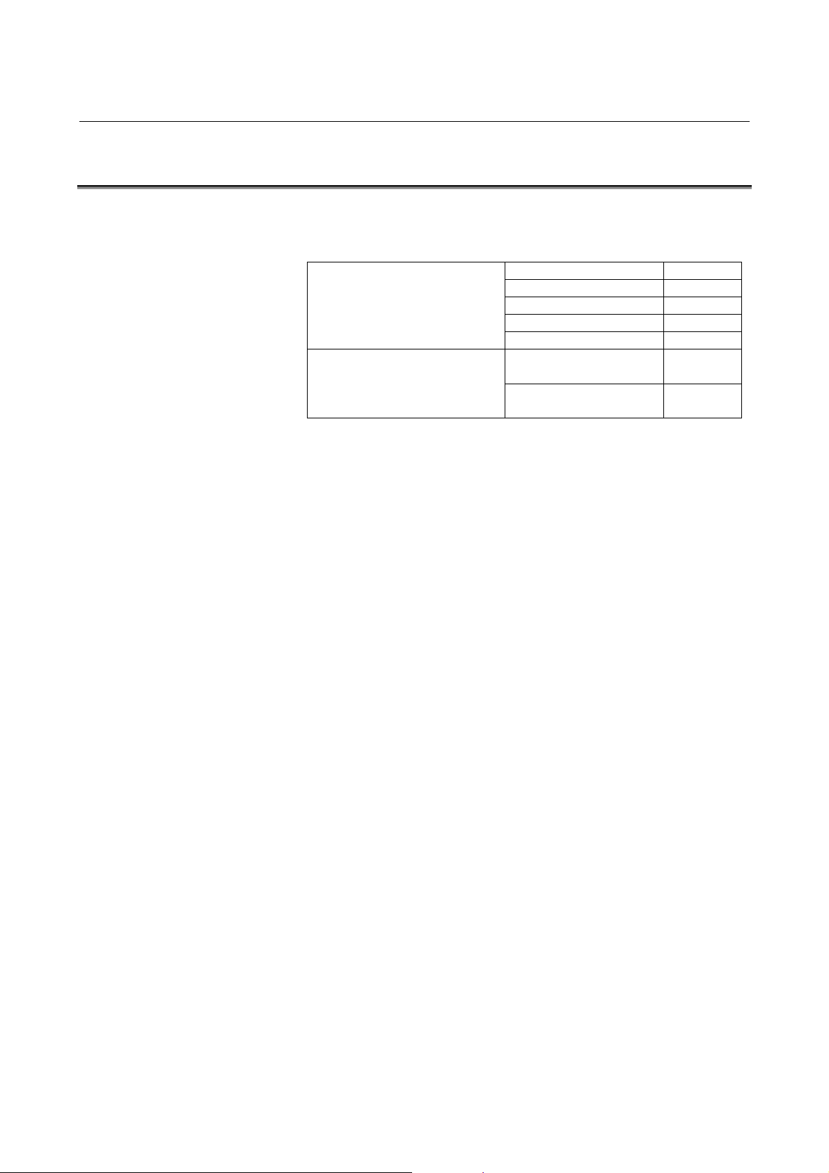
1.2 APPLICABLE MODELS
This manual covers the following models:
Model Abbreviation
FANUC LASER C1000-MODEL E C1000-E
FANUC LASER C2000-MODEL E C2000-E
FANUC LASER C4000-MODEL E C4000-E
- 3 -
Page 12
1.OVERVIEW B-70265EN/01
1.3 RELATED MANUALS
The following manuals are available for the FANUC LASER C1000/
C2000/C4000-MODEL E :
DESCRIPTIONS B-63192EN
CONNECTION MANUAL B-63193EN
FANUC Series 16i-LA
OPERATOR’S MANUAL B-63194EN
MAINTENANCE MANUAL B-63195EN
PARAMETER MANUAL B-63200EN
FANUC LASER
C1000/C2000/C4000-MODEL E
OPERATOR’S MANUAL B-70264EN
MAINTENANCE MANUAL
(This manual)
B-70265EN
- 4 -
Page 13
B-70265EN/01 1.OVERVIEW
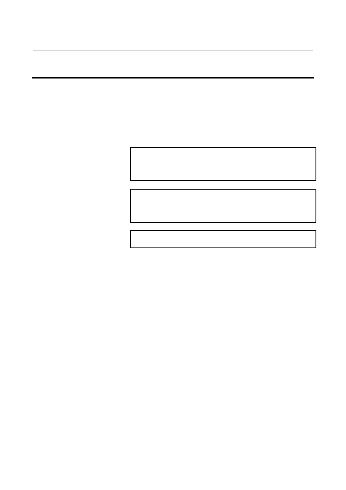
1.4 TO USE THE LASER OSCILLATOR SAFETY
This manual contains precautions which must be observed during
operation of the laser oscillator, to ensure the operator's safety and
prevent damage to the oscillator. Each precaution is indicated by
"Warning" or "Caution" according to its severity.
Supplementary information is indicated by "Note".
Read the contents of each "Warning", "Caution", and "Note" before
attempting to use the oscillator.
WARNING
Precautions to be applied in those situations where
there is a danger of the operator being killed or
seriously injured.
CAUTION
Precautions to be applied in those situations where
there is a danger of the operator being slightly
injured or the oscillator being damaged.
NOTE
Supplementary information other than precautions.
The functions of a laser machining system depend not only on the
laser oscillator, but also on the machine, power magnetics cabinet,
servo system, CNC, and operator's panel. This manual describes only
the laser oscillator. For a description of the other components, refer to
the corresponding manuals, supplied by the machine tool builder.
- Read this manual thoroughly and store it in a safe place.
- 5 -
Page 14

2.SAFETY B-70265EN/01
2 SAFETY
This chapter describes precautions to be observed to ensure the safe
operation of the laser oscillator.
Read this chapter thoroughly before attempting to use the laser
oscillator.
Also, read the safety precautions in the operator's manual supplied by
the machine tool builder.
The laser oscillator may present a danger not only to the operator but
also to other people working around the oscillator, up to a
considerable distance away. The laser oscillator must, therefore, be
operated only by a person who has received appropriate training.
Only persons who have understood the internal structure of the laser
oscillator and have received appropriate training can maintain the
laser oscillator.
A warning label is put on each dangerous position of the laser
oscillator. Be extremely careful about the labeled positions.
- 6 -
Page 15

B-70265EN/01 2.SAFETY
2.1 WARNING
(1) It is extremely dangerous to expose your eyes to direct, scattered,
or reflected CO
while the laser is operating.
Exposure to laser light can cause blindness. If your eyes are
accidentally exposed, seek medical advice immediately.
(2) Do not turn on the laser oscillator while a panel is removed or a
door is open.
Operating the laser with a door open or panel removed may
result in the operator being directly exposed to CO
radiation. Exposure to laser light can cause blindness and/or
severe burns. If your eyes are accidentally exposed to laser light,
seek medical advice immediately.
Before turning on the power during maintenance if absolutely
necessary, wear protective glasses and clothing to prevent
accidents.
laser light. Always wear protective glasses
2
laser
2
(3) If the laser oscillator is operated with a panel open, ultraviolet
radiation is emitted from the high-frequency discharge section.
Gazing the discharge section for a long time can cause visual
disturbances such as impaired eyesight.
Always wear protective glasses during work. If you feel trouble
with your eyes, seek medical advice immediately.
(4) Surround the laser machining tool with a fence made of a
material which absorbs laser light well (such as acrylic). Place
appropriate warning notices on the fence.
The door in the safety fence shall be fitted with an interlock
switch such that opening the door stops the laser.
Failure to provide such a fence exposes persons in the vicinity of
the machine tool to the danger of being exposed to CO
laser
2
radiation and the associated risk of blindness. If a person is
accidentally exposed to laser light, seek medical advice
immediately.
(5) The laser beam shall be no higher than average eye height.
Enclose the path of the laser beam with covers. Do not leave the
end of the beam path open. Place laser- absorbing material at the
end of the beam path to absorb the beam's energy.
A CO
laser beam is directional and has a high energy density.
2
Exposure to laser light can cause blindness. Flammable material
may burn or explode if exposed to the laser beam. If your eyes
are accidentally exposed to laser light, seek medical advice
immediately.
- 7 -
Page 16

2.SAFETY B-70265EN/01
(6) A high voltage of 3 to 4 kV
is applied to some places in the
0-p
laser oscillator cabinet. Therefore, do not turn the power to the
oscillator on or operate the oscillator when an oscillator panel is
open. Operating the laser oscillator with a panel open can cause
a touch on a high-voltage place, resulting in electric shock.
Before turning on the power during maintenance if absolutely
necessary, take measures against accidents.
(7) Before daily inspection, the replacement of a maintenance part
or maintenance, open the main circuit breaker and turn the power
supply off (double power-off).
To prevent the power from being inadvertently turned on, lock
the circuit breaker open, and affix an indication of work in
progress.
Failure to turn off the power during inspection or replacement
exposes the operator to the danger of electric shock.
Before turning on the power during maintenance if absolutely
necessary, take measures against accidents.
(8) The oscillator output mirror and focusing lens on the machining
head both have a substrate made of ZnSe (zinc selenide), a toxic
substance. Therefore, do not touch the mirror or lens with your
bare hands.
Inhaling ZnSe dust may cause difficulty in breathing, completely
stopping the breathing of the victim in the worst case.
If you accidentally touch the mirror or lens with your bare hands,
wash your hands well under running water.
If you accidentally inhale ZnSe dust or debris, seek medical
advice immediately.
(9) Do not look at the machining point without eye protection.
Otherwise, your eyes may be exposed to reflected laser light,
resulting in blindness.
If your eyes are accidentally exposed to laser light, seek medical
advice immediately.
(10) Before attempting to machine any material for the first time,
consult with the manufacturer of the material.
Some materials generate toxic gases when cut or drilled by a
laser beam.
Should you accidentally inhale any toxic gas, seek medical
advice immediately.
(11) If the laser oscillator must be moved, entrust the work to the
machine tool builder whenever possible. If performed by
inexperienced personnel, the oscillator may topple or be dropped,
resulting in a potentially fatal accident.
When the machine tool builder is not available to move the
oscillator, follow the procedure described on the hanging method
label. While moving the oscillator, stand well clear and never
pass under the oscillator.
- 8 -
Page 17

B-70265EN/01 2.SAFETY
(12) Do not allow any dangerous or high-pressure gas to get into the
oscillator housing. The oscillator cabinet has a hermetic structure
(dustproof and dripproof), it cannot be ventilated easily.
Flammable gases such as oxygen can cause a fire or explosion.
Toxic gases can harm operators during maintenance. Organic
gases can degrade machining performance. High-pressure gases
can damage a panel or the cabinet, resulting in injury from flying
matters.
If such a gas accidentally gets into the oscillator housing, remove
a panel for ventilation. The installation room must be also well
ventilated.
To purge the oscillator housing, use purified, low-pressure air or
nitrogen.
- 9 -
Page 18

2.SAFETY B-70265EN/01
2.2 CAUTION
(1) If there is a possibility of being exposed to CO2 laser radiation
exceeding the maximum permissible exposure (MPE) level for
skin, wear protective clothing.
Otherwise, there is a danger of being burnt.
(2) Oscillator is fitted with a red semiconductor laser to indicate the
approximate position of invisible CO
directly at the semiconductor laser beam. Otherwise, your eyes
may be injured.
(3) The gas circulating system in the oscillator becomes very hot.
Do not touch the gas pipes, turbo blower, heat exchanger, or
exhaust pump, until they have cooled down sufficiently after the
oscillator has been turned off. Otherwise, you may be burnt.
(4) Do not pass your hand in the optical path of the laser machine or
under the laser head when the shutter of the oscillator is open.
When the shutter is open, a laser beam may be emitted from the
oscillator accidentally. Before work in the optical path or under
the laser head, confirm that the shutter is closed.
laser beam. Do not look
2
(5) The workpiece becomes very hot during machining. Never touch
the workpiece with your bare hands. Otherwise, you may be
burnt.
(6) During machining, extremely hot chips are likely to be
generated.
Unless sufficient caution is exercised, there is a danger of the
operator being burnt, or of a fire being started.
(7) Some materials may burn or explode when laser machined.
Before attempting to machine any material for the first time,
consult with the manufacturer of the material, to prevent the
danger of fire of or the possibility of operator injury.
(8) The oscillator contains cooling fan units. Although the fan units
are fitted with a finger guard, to prevent injury, keep your hands
well away from the fans.
(9) The oscillator is controlled according to the CNC internal
parameter settings. If a numeric value different from a setting is
entered and the oscillator is operated, the oscillator may
malfunction. In the worst case, the oscillator may be damaged.
- 10 -
Page 19

B-70265EN/01 2.SAFETY
2.3 NOTE
(1) During installation or maintenance necessitating the opening of
an oscillator door or the removal of a panel, only persons who
have undergone maintenance training should operate the laser. In
such a case, extreme caution must be exercised.
(2) Warning labels are affixed to those parts of the oscillator where
there is a danger of exposure to laser radiation. Observe the
precautions given on the labels. (Section 2.4 shows the warning
labels.)
(3) Laser products shall conform to the regulations laid down in the
laser safety standard, including that stipulating control using a
key.
The oscillator start signal (RUN ON) shall be controlled with a
key switch such that the oscillator cannot be turned on without a
specific key.
Control using a key ensures that other than the authorized
personnel cannot operate the laser oscillator. It is extremely
dangerous if a person who is unfamiliar with the equipment
attempts to operate the laser oscillator.
(4) The shutter shall be unlocked only while a beam is being output.
Otherwise, keep the shutter locked to provide protection should
the laser accidentally be turned on.
(5) Do not discard a used output mirror or focusing lens together
with regular waste. If the output mirror or focusing lens is
replaced, return the original to the supplier or entrust it to a
specialized disposal company.
(6) Do not place any flammable material (such as paper, cloth, or
wood) near the workpiece table.
(7) Keep a fire extinguisher beside the unit.
(8) Oscillator is equipped with an alarm lamp. The alarm lamp
blinks while discharge is in progress or whenever laser radiation
is possible.
While the alarm lamp is blinking, pay careful attention to laser
radiation and high voltages.
- 11 -
Page 20
2.SAFETY B-70265EN/01
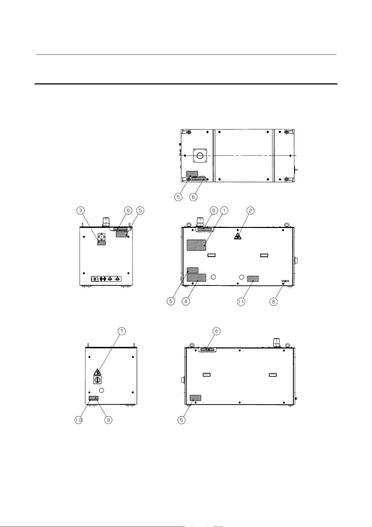
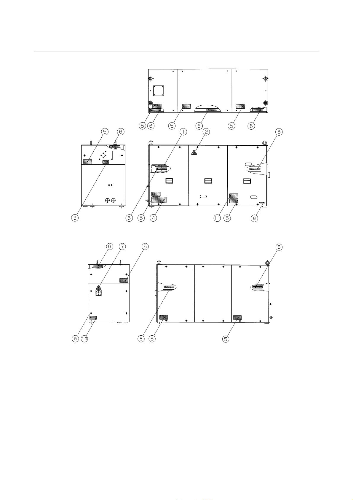
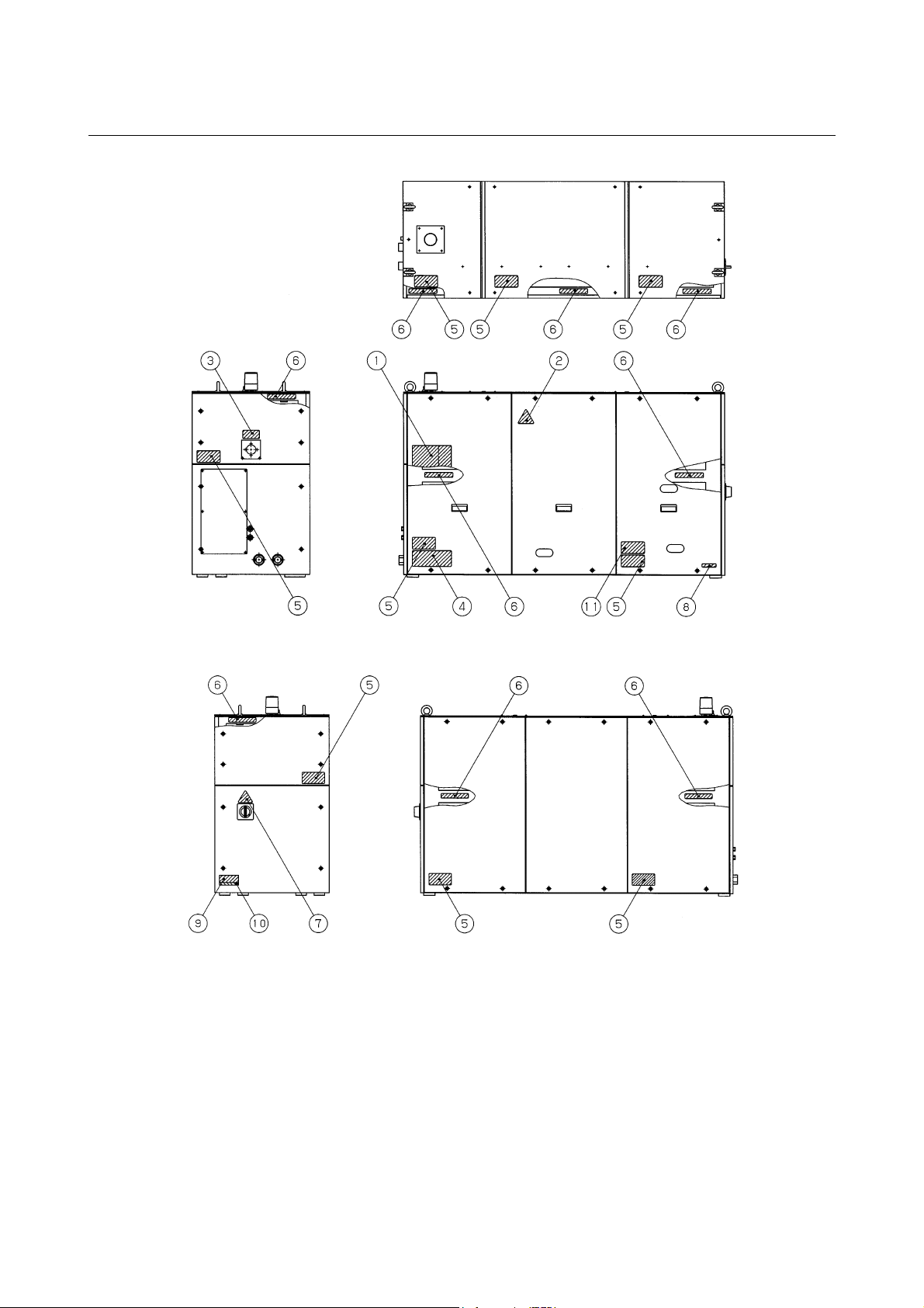
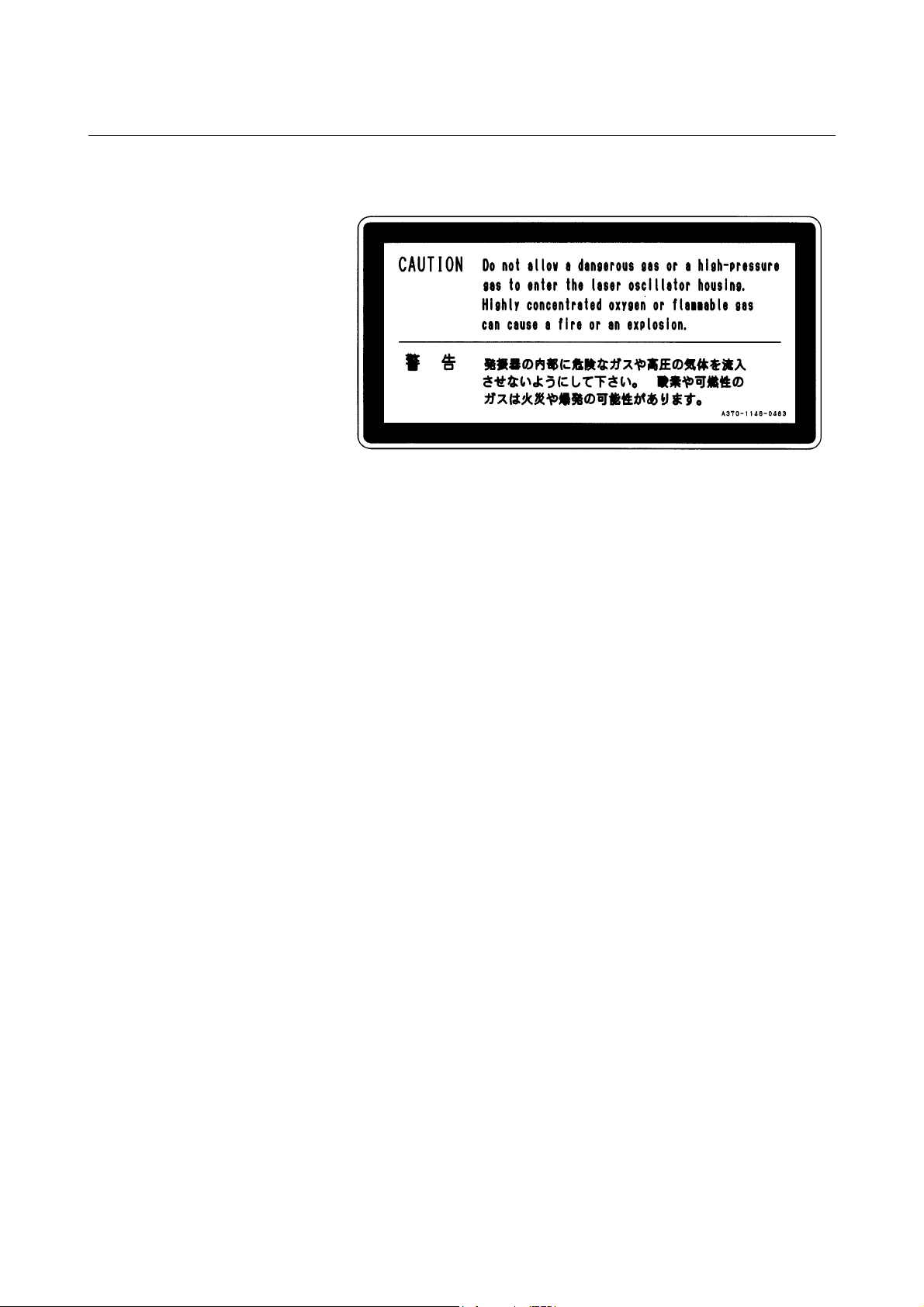
2.4 WARNING LABELS
The oscillator uses high voltages and laser beam radiation. Such
hazards are indicated with warning labels attached to the positions
shown in Fig.2.4 (a) to (f).
Fig.2.4(a) Warning label positions (C1000-E : front view)
Fig.2.4(b) Warning label positions (C1000-E : rear view)
- 12 -
Page 21
B-70265EN/01 2.SAFETY
Fig.2.4(c) Warning label positions (C2000-E : front view)
Fig.2.4(d) Warning label positions (C2000-E : rear view)
- 13 -
Page 22
2.SAFETY B-70265EN/01
Fig.2.4(e) Warning label positions (C4000-E : front view)
Fig.2.4(f) Warning label positions (C4000-E : rear view)
- 14 -
Page 23
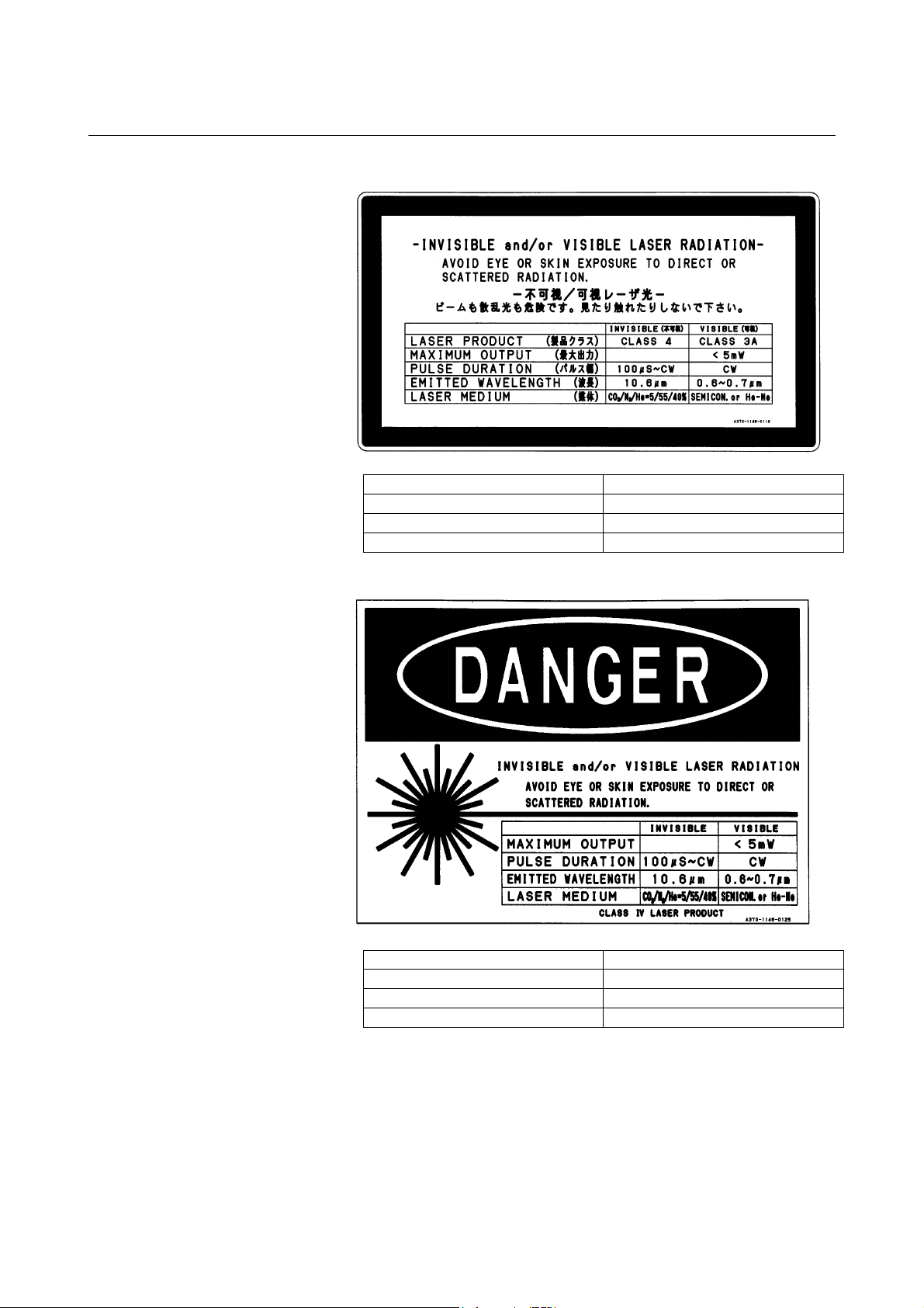
B-70265EN/01 2.SAFETY
(1) Class indication label (JPN)
MAXIMUM OUTPUT
C1000-E
C2000-E
C4000-E
2000W
5000W
8000W
(1) Class indication label (FDA)
C1000-E
C2000-E
C4000-E
MAXIMUM OUTPUT
2000W
5000W
8000W
- 15 -
Page 24
2.SAFETY B-70265EN/01
(2) Warning label
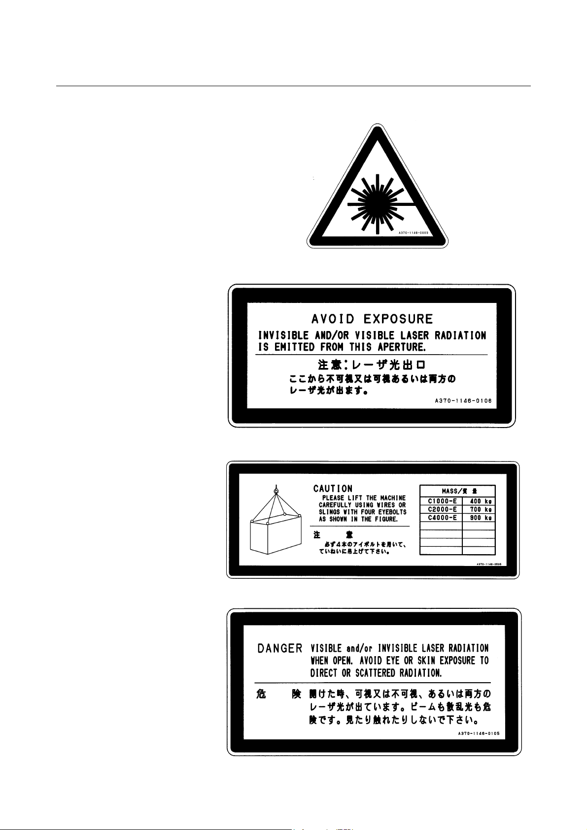
(3) Aperture label
(4) Suspension method label
(5) Access panel
- 16 -
Page 25
B-70265EN/01 2.SAFETY
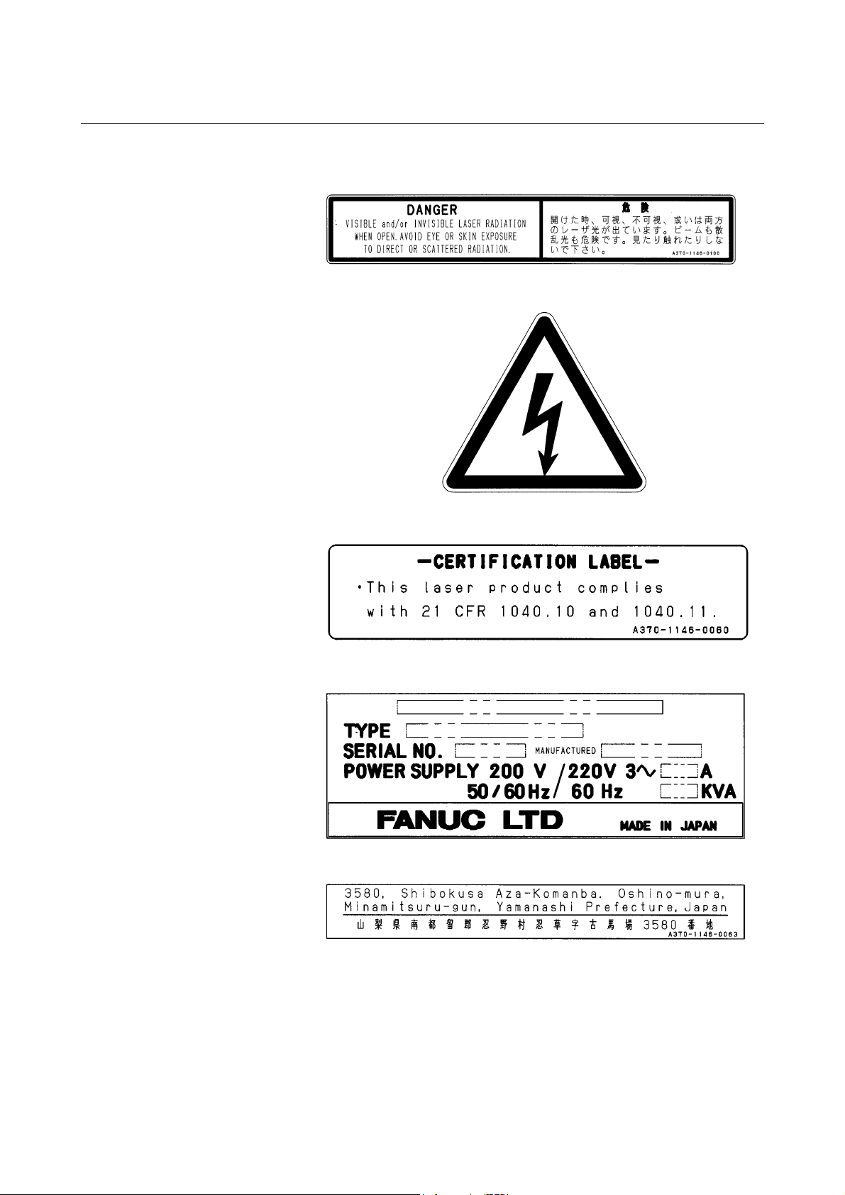
(6) Label inside the access panel
(7) Discharge section label
(8) Certification label
(9) Equipment nameplate
(10) Manufacturer's address label
- 17 -
Page 26
2.SAFETY B-70265EN/01
(11) Label for regulating the atmospheric gases in the oscillator
housing
- 18 -
Page 27
B-70265EN/01 2.SAFETY
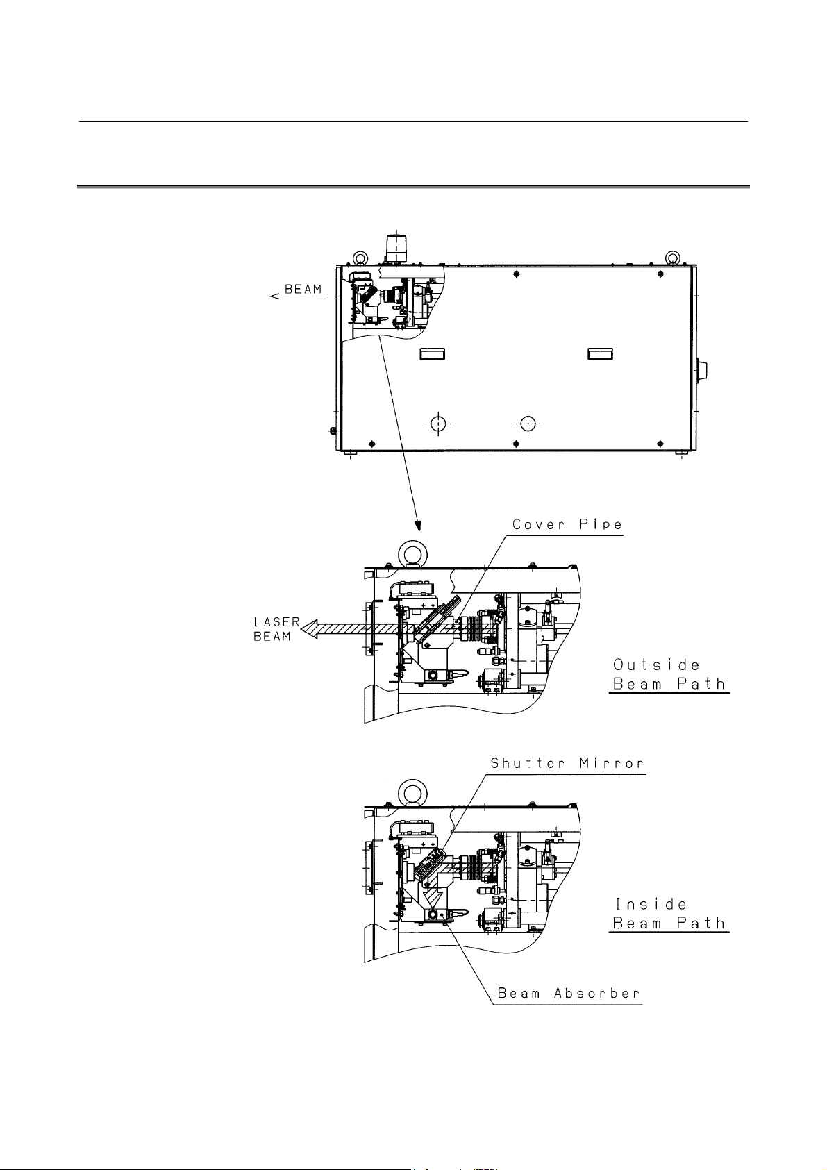
2.5 OPTICAL PATHS IN THE OSCILLATOR
The figures below show the laser optical paths inside the oscillator.
Fig.2.5(a) Optical paths in the C1000-E
- 19 -
Page 28
2.SAFETY B-70265EN/01
Fig.2.5(b) Optical paths in the C2000-E
Fig.2.5(c) Optical paths in the C4000-E
- 20 -
Page 29

B-70265EN/01 3.INTERNAL STRUCTURE
3 INTERNAL STRUCTURE
- 21 -
Page 30
3.INTERNAL STRUCTURE B-70265EN/01
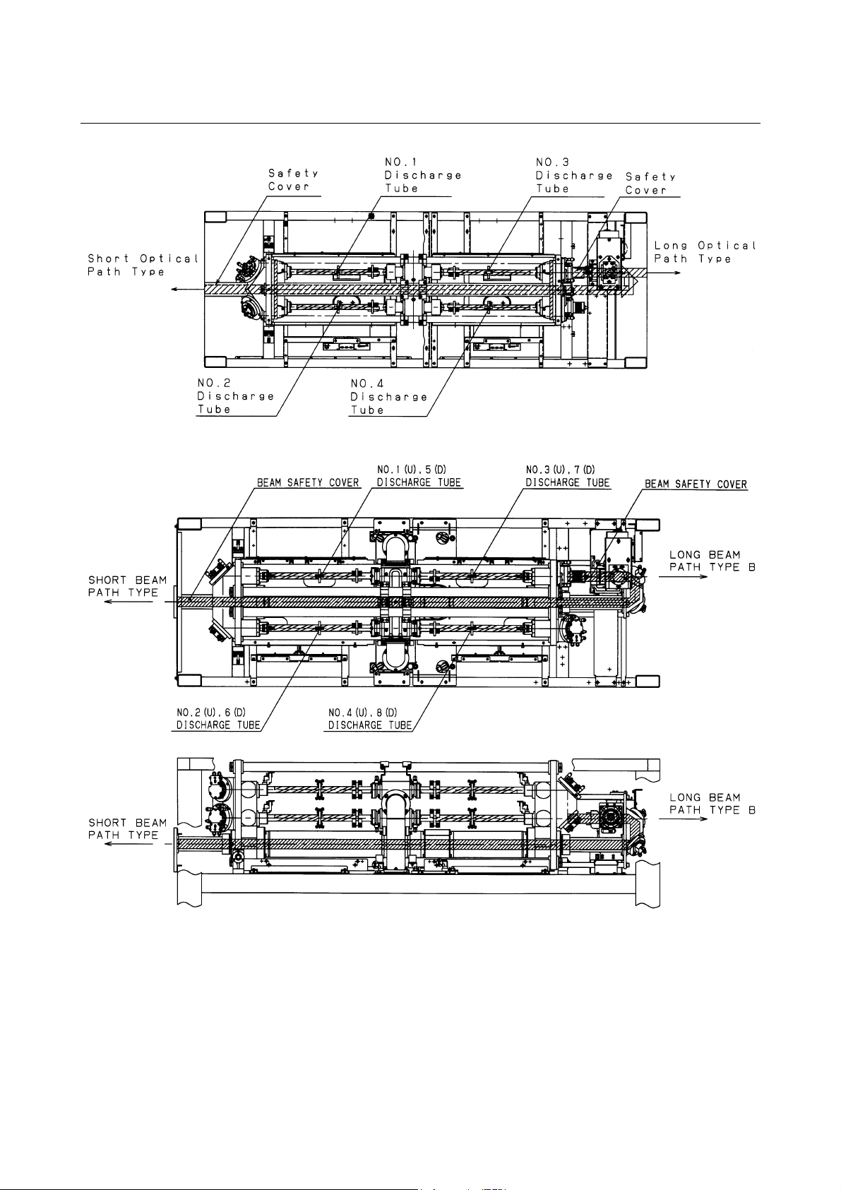
3.1 OUTLINE
Figs.3.1(a) to (c) show the internal structure of the laser oscillator.
The oscillator consists of a laser resonator, discharge drive unit,
forced gas circulating system, pressure controller, CNC interface, and
a protective housing.
Fig.3.1(a) C1000-E internal structure
Fig.3.1(b) C2000-E internal structure
- 22 -
Page 31

B-70265EN/01 3.INTERNAL STRUCTURE
Fig.3.1(c) C4000-E internal structure
(1) Laser resonator
The laser resonator consists of several discharge tubes,
connected in series using folding mirrors, with a rear mirror and
output mirror placed at the open ends of the discharge tubes, thus
sealing the tubes. The resonator is fitted with a gas pipe
connecting port through which laser gas is fed into the discharge
tubes.
A discharge from the electrodes of the discharge tube energizes
CO
molecules, which emit light. This light is amplified by
2
stimulated emission, repeated between the rear mirror and output
mirror, a laser beam being emitted from the output mirror.
(2) Discharge drive unit
The discharge drive unit consists of a laser power supply,
matching box, and discharge tubes. High-frequency output of 2
MHz that is controlled by the CNC discharges the laser gas
flows through discharge tubes to energize CO
molecules.
2
(3) Forced gas circulating system
A gas circulating system is configured by connecting the
resonator and turbo blower with a circulating pipe. Laser gas is
forced through the discharge tubes at a speed of 200 m/s or
higher.
A water-cooled heat exchanger, used to cool the hightemperature gas from the discharge tubes, is provided at the inlet
side of the turbo blower. At the outlet side of the turbo blower,
another water-cooled heat exchanger dissipates the compression
heat.
- 23 -
Page 32

3.INTERNAL STRUCTURE B-70265EN/01
(4) Pressure controller
The laser gas pressure within the forced gas circulating system is
controlled by commands issued from the CNC, thus ensuring
stable laser output.
(5) CNC interface
Interface used to connect a FANUC Series 16i-L. CNC
commands that, control the operation of the laser oscillator, such
as start/stop and laser output, are input via this interface.
(6) Protective housing
An enclosure that houses the above components. The housing,
consisting of metal panels, completely encloses the laser
oscillator, thus protecting the operator from exposure to laser
radiation and from high voltages. All panels are screw-fixed and
cannot be removed without an appropriate tool.
- 24 -
Page 33

B-70265EN/01 3.INTERNAL STRUCTURE
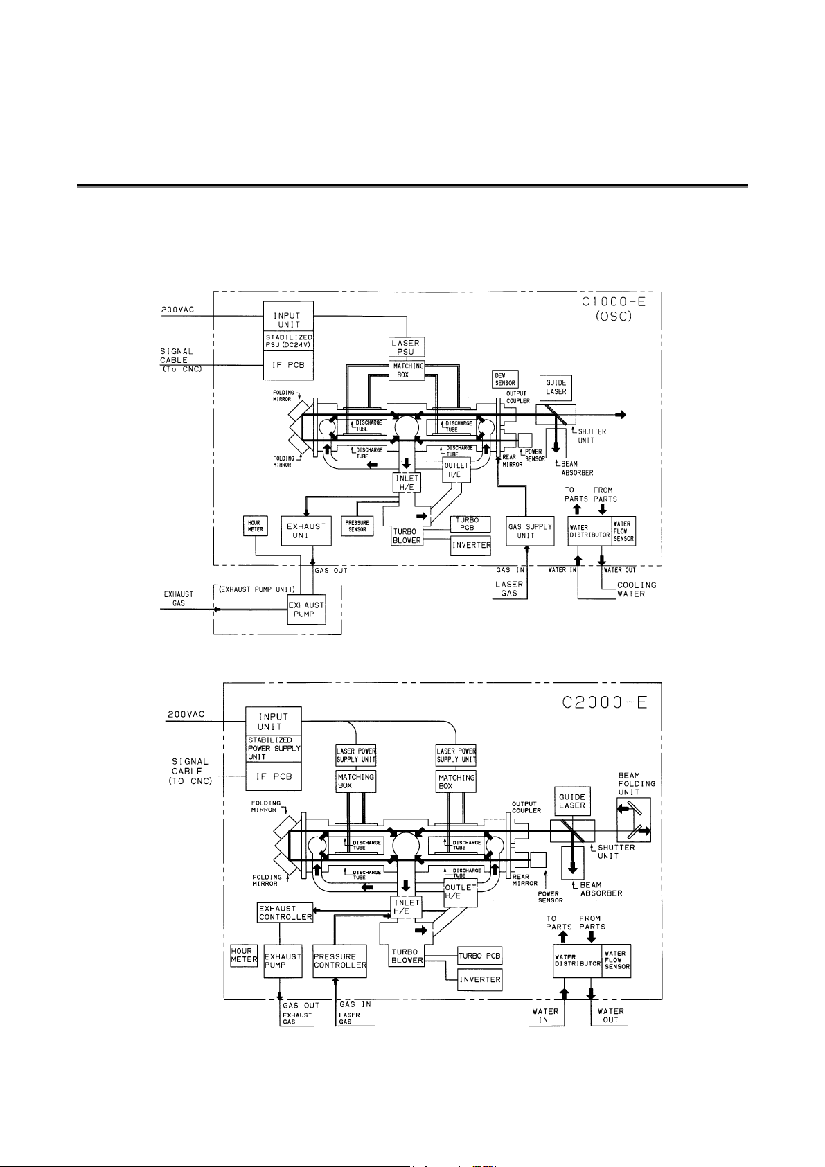
3.2 COMPONENT DETAILS
This section describes the internal structure of the oscillator more
specifically. Figs.3.2(a) to (c) are internal structural drawing.
Fig.3.2(a) C1000-E structural drawing
Fig.3.2(b) C2000-E structural drawing
- 25 -
Page 34

3.INTERNAL STRUCTURE B-70265EN/01
Fig.3.2(c) C4000-E structural drawing
(1) Resonator
The resonator consists of an output mirror, rear mirror, folding
mirrors, discharge tubes, power sensor unit, etc. It converts
electrical energy first to laser gas, then to optical energy (10.6µm single-wavelength laser beam).
(2) Output mirror
A transmitting/reflecting mirror which outputs the laser beam
after it has been amplified. The output mirror consists of a ZnSe
(zinc selenide) substrate, coated with dielectric. ZnSe is tightly
toxic. Be particularly careful, therefore, when handling the
output mirror.
(3) Rear mirror
A reflecting mirror consisting of a Ge (germanium) substrate,
coated with dielectric.
Having a high reflectance of 99.5%, the rear mirror is used to
reflect the laser beam within the resonator while transmitting
0.5% of the laser light so that the beam can be monitored
externally.
(4) Folding mirror
A mirror unit which reflects the laser beam at a 90-degree angle.
The folding mirror consists of a block with a surface tilting to a
45-degree angle and an Si (silicon) substrate, coated with
multilayer dielectric film.
(5) Discharge tube
A pair of Ag (silver) electrodes are metallized on the surface of a
hollow quartz glass pipe. A high-frequency discharge between
these electrodes injects electrical energy into the laser gas. Each
electrode is coated with ceramic, preventing it from degrading
and thus improving system reliability.
- 26 -
Page 35

B-70265EN/01 3.INTERNAL STRUCTURE
(6) Trigger electrode
A predischarge placed outside the laser oscillation area can
facilitate the start of the main discharge. With it, the laser output
is zero when the beam is off.
(7) Power sensor
An optical sensor which detects the intensity of the laser beam,
transmitted through the rear mirror, thus enabling monitoring of
the laser output level.
(8) Gas circulating system
A gas circulating path including a turbo blower, heat exchangers,
and circulating pipes, which circulates laser gas in the discharge
tubes at high speed.
(9) Turbo blower
During laser oscillation, the laser gas pressure is 1330 – 9310 Pa.
The turbo blower circulates this rough-vacuum gas at high speed
without contaminating the gas.
(10) Heat exchanger (inlet)
Water-cooled heat exchanger used to cool the laser gas that has
been heated by discharge, before it is drawn into the turbo
blower.
(11) Heat exchanger (outlet)
Water-cooled heat exchanger used to cool the laser gas that has
been heated by compression in the turbo blower, before being
forced into the discharge tubes.
(12) Gas controller (C1000-E)
The gas controller always monitors the gas pressure in each
discharge tube and supplies the fresh laser gas to the circulating
system to keep the pressure constant. It also monitors the supply
status of the laser gas, purge check for the circulating system,
and other items and has a function of adjusting the amount of
flow of the gas to be exhausted.
(13) Pressure control unit (C2000-E, C4000-E)
The pressure control unit always monitors the gas pressure in
each discharge tube and supplies the fresh laser gas to the
circulating system to keep the pressure constant. It also monitors
the supply status of the laser gas, purge check for the circulating
system, and other items.
- 27 -
Page 36

3.INTERNAL STRUCTURE B-70265EN/01
(14) Exhaust pump unit
This unit is used to vacuum-exhaust laser gas from the gas
circulating system such that its pressure falls to that used for
laser oscillation. Also, within this unit, a small amount of
circulating gas is constantly being exchanged, to prevent
degradation of the circulating gas.
For the C1000-E, the exhaust pump is installed separately.
(15) Exhaust control unit (C2000-E, C4000-E)
The exhaust control unit is capable of controlling the flow rate of
laser gas to be exhausted. It switches gas flow rates at gas
replacement and for pressure control.
(16) Hour meter
The hour meter indicates the total number of hours that the laser
oscillator has operated (how many hours the exhaust pump has
operated), to indicate whether maintenance or inspection is
necessary.
(17) Shutter
The shutter has a rotary arm operated by a rotary solenoid and an
Au (gold)-evaporated reflecting mirror attached to the arm.
It can be opened and closed by CNC commands. It also has a
position sensor and a temperature sensor for safety and always
monitors the open/close status and shutter temperature.
(18) Beam absorber
While the laser oscillator is operating with the shutter closed, the
laser beam is guided into the beam absorber. The beam absorber
absorbs nearly 100% of laser beam and is water-cooled, allowing
it to safely absorb the beam for relatively long periods. For
safety, the beam absorber is equipped with a temperature sensor
which allows the system to monitor the temperature of the beam
absorber.
(19) Distribution unit
This unit distributes cooling water, supplied from either a chiller
unit or a temperature-regulated external water supply, to each
unit in the laser oscillator.
For safety, the water distribution unit is equipped with a flow
sensor which allows the system to monitor the flow rate of the
cooling water.
(20) Laser power supply
A power supply for generating a discharge in each discharge
tube. The laser power supply receives the three-phase AC input
at 200/220V and outputs 2-MHz high-frequency power
controlled with stability by commands from the CNC.
The RF inverter converts DC power to 3 to 4 kVPO-P highfrequency (2 MHz) power, then outputs it to the matching box.
- 28 -
Page 37

B-70265EN/01 3.INTERNAL STRUCTURE
(21) Matching box
The matching box contains a matching circuit, consisting of coils
and capacitors, which ensures that power is effectively input to
the discharge tubes.
(22) Intermediate PCB B
This PCB transmits signals output by the shutter section, such as
those from the limit switch, absorber temperature sensor, power
sensor, and condensation sensor, to the interface PCB.
(23) Input unit
The power magnetics cabinet distributes power, supplied from
an external unit, to each unit in the laser oscillator. It also
protects each unit from overcurrents.
(24) Input unit control PCB
This PCB has functions of transmitting the contactor open/close
signals according to CNC commands and of notifying the CNC
of the open/close status of the circuit breaker in the input unit.
(25) Interface PCB
Transfers signals to and from the CNC via the FANUC I/O Link
(serial interface).
(26) Stabilized power supply
This unit converts the 200/220 VAC power source to DC power
for the interface PCB and other units.
(27) Condensation sensor
The condensation sensor is mounted above the output mirror
holder. If condensation occurs on this sensor, the resistance
changes, an alarm (abnormal water temperature) occurs, and the
oscillator is stopped. It prevents faults in each unit from
occurring due to condensation.
(28) Inverter
This inverter drives the turbo blower. It is responsible for
acceleration/deceleration control during start and stop of the
blower.
(29) Turbo PCB
This PCB monitors overheating, the oil level, and frequency
reached signal of the turbo blower.
- 29 -
Page 38

3.INTERNAL STRUCTURE B-70265EN/01
(30) Guide laser (laser diode)
A laser diode is overlaid on the same optical axis as a guide
beam for checking the optical axis because the CO
invisible to the unaided eye. The guide beam is emitted in
synchronization with the mechanical shutter only when the
shutter is closed. The guide laser can be used for roughly
adjusting the optical path of an external optical system and for
obtaining a guide for the machining point.
(31) Beam folding unit
This unit reverses the direction of the laser beam in the oscillator
laser beam is
2
- 30 -
Page 39

B-70265EN/01 4.INSTALLATION
4 INSTALLATION
- 31 -
Page 40

4.INSTALLATION B-70265EN/01
4.1 INSTALLATION PROCEDURE
Use the following procedure to make adjustments and checks during
installation.
(1) Check the environment at the installation location.
[Environmental conditions]
1 Ambient temperature +5 to +30 °C
2 Temperature variation 1.1°C /minute maximum
3 Humidity 75% or below (relative humidity)
4 Vibration Acceleration not to exceed 0.05G.
Vibration amplitude not to exceed 5µm.
5 Atmosphere Dust must be minimized.
There must be no organic volatile
components.
6 Laser gas Composition
CO
: 5 ± 0.25 % Purity
2
He : 40 ± 2.0 % 99.99 %
N
: 55 ± 2.75 % or more
2
H
O : 5 ppm maximum
2
CmHn : 1 ppm maximum
- 32 -
Page 41

B-70265EN/01 4.INSTALLATION
(2) Remove resonator and shutter clamps.
The clamps are used only in transit. In particular, loosen the
resonator clamp before it is stored. If the resonator is left for a
long time with the clamp tightened, the resonator is likely to be
deformed. The clamp locations are shown in Figs.4.1(a) to (c).
Shutter clamp
Resonator
clamp
Details of resonator
clamp and shutter clamp
Fig.4.1(a) Details of resonator and shutter clamps section (C1000-E)
- 33 -
Page 42

4.INSTALLATION B-70265EN/01
Shutter clamp
Resonator clamp
Details of resonator
Details of shutter clamp
Fig.4.1(b) Details of resonator and shutter clamps section (C2000-E)
clamp
- 34 -
Page 43

B-70265EN/01 4.INSTALLATION
Resonator
clamp A
Resonator
clamp B
Shutter clamp
Details of shutter clamp
Details of resonator
clamp A
Fig.4.1(c) Details of resonator and shutter clamps section (C4000-E)
Details of resonator
clamp B
- 35 -
Page 44

4.INSTALLATION B-70265EN/01
(3) Check the outsides of units installed in the oscillator as follows:
Check items
1 Check whether any printed circuit boards are loose or removed.
2 Check whether any cables are damaged (such as damaged sheathing).
3 Check whether any connectors are loose or detached.
4 Check that the discharge tubes are neither cracked nor damaged.
5 Check that the turbo blowers and other units are neither loose nor
missing.
6 Check that the power supply units and matching boxes are neither
loose nor missing.
7 Check that the input unit is neither loose nor missing.
8 Check that the connection to the electrode of each discharge tube is not
loose.
9 Check whether any joint part of the water piping and gas piping is loose.
10 Check all screw terminals in the units.
11 Check the oil level in the turbo blowers, and check for oil contamination.
(See Section 5.3 for details.)
(4) Connect the power and signal lines to the oscillator. (See
Subsection 4.4.3 for details.)
Check items
1 Signal cable between the NC and oscillator (optical fiber), 24V DC
2 Oscillator power cable
3 Grounding cable (class-1)
4 Exhaust pump power cable (See Subsection 4.4.4 for details.)
(only for C1000-E)
On the C1000-E, connect the power cable of the exhaust pump
(to the oscillator and pump).
(5) Check the communication setting on the interface PCB. (See
Subsection 6.5.5 for details.)
When a metal cable is used : LINK1 (JD1)
When an optical fiber cable is used : LINK1 (COP)
(6) Laser gas and cooling water pipes. (See Subsections 4.4.1 and
4.4.2 for details.)
Check items
1 Laser gas pipe type
Recommended gas pipe
Nylon tube AS1, manufactured by Junko Co. Ltd.
Polyprotube, manufactured by Imperial Co. Ltd.
Stainless bright anneal pipe
2 There must be no gas leakage in the external piping between the gas
cylinder and oscillator.
3 Laser gas composition and purity (Check whether the specifications are
satisfied.)
4 Quality of cooling water (Tap water passed through an ion exchanger is
recommended.)
5 Flow of cooling water (IN, OUT)
6 Connection of the gas feeder piping of the exhaust pump
Connect the gas feeder piping of the exhaust pump (to the
oscillator and pump).
- 36 -
Page 45

B-70265EN/01 4.INSTALLATION
(7) Check the input power supply voltage, frequency and phase
sequence. (See Section 6.5 for details.)
(8) Turn on the power, then check the operation of the fan motors in
the housing.
The fan motors installed in the oscillator start as soon as the
power to the CNC is turned on. Check the operation of each fan
motor. Note, however, that the fan motor installed in the laser
power supply does not start until the oscillator sequence reaches
the turbo blower ON operation.
(9) Check the parameters and setting data.
Check the parameters against the data sheets attached to the
oscillator. If a value other than those given on the data sheets is
set, correct the setting. Note, however, that parameter No. 15270
and parameter No. 15204 are set automatically, so that these
parameters need not be modified.
CAUTION
Each oscillator has unique parameters. Check the
setting data according to the attached data sheets.
Be particularly careful to store these data sheets
safely.
(10) Check that cooling water is supplied normally, and that there is
no water leakage inside the oscillator or at any external
connection points.
(a) Turn off the main circuit breaker of the oscillator and
power supply.
(b) Check that the water inlet (IN) and outlet (OUT) of the
oscillator are connected correctly. If the water inlet and
outlet are connected incorrectly, the flow sensor mounted
on the outlet does not function, which prevents water from
flowing.
(c) Fully open the valves on the exhaust side so that the flow of
water is not impeded. By manually operating the chiller unit,
pass cooling water through the system at a flow rate of
about 10 liters/minute. Then, check that there is no water
leakage at the following locations:
1. The water inlet (IN) and outlet (OUT) of the oscillator
2. The water piping (including all tubes and joints) in the
oscillator
(d) Provided no water leakage is observed in step 3) above,
allow cooling water to flow through the oscillator at the
specified flow rate. Set the output pressure of the cooling
water circulating unit to 0.5 MPa(5 bar). Then, check that
there is no water leakage at the following locations:
1. The water inlet (IN) and outlet (OUT) of the oscillator
2. The water piping (including tubes and joints) in the
oscillator
- 37 -
Page 46

4.INSTALLATION B-70265EN/01
(e) Stop the chiller unit, then switch the operation mode from
manual (local) mode to automatic (remote) mode.
(f) If there is no water leakage, set the RUN key to ON to start
the oscillator. Check that the cooling water circulating unit
can be operated according to commands issued from the
CNC. If the flow rate is less than the specified value, alarm
No. 4072 (low cooling water flow rate) is issued soon after
the chiller unit is started. If this alarm is issued, proceed as
indicated in the guidance corresponding to this alarm.
(g) Check that the temperature of the cooling water is set to
room temperature plus 1°C. (The temperature of the cooling
water may be set to about 27°C throughout the year.) The
highest temperature that may be set is 30°C.
(11) Conduct an oscillator vacuum leakage test.
(a) Check the oscillator for any internal leakage.
The procedure for performing a leakage check is given in
Subsection 4.3.3.
(b) When first starting the oscillator, check that gas is output
from the gas outlet of the oscillator. Depending on the
parameter settings, it may take as long as one minute before
gas is output. If no gas is output, the exhaust pump rotation
may be reversed. Immediately turn off the circuit breaker to
stop the exhaust pump. If this situation is left uncorrected,
the exhaust pump may ultimately start to make an abnormal
sound, and the thermal switch may trip. In the worst case,
the gas circulating system may be contaminated with
exhaust pump oil.
(12) Check that the laser gas pressure is controlled normally.
(a) Set all bits of parameter No. 15025 through parameter No.
15028 to 0 because only the pressure control operation is to
be checked, without causing discharge. Set parameter No.
15240 to the standard value 10, then check the pressure
control status of the laser oscillator. Start the oscillator
(RUN ON), and check the pressure control status under the
following parameters while checking DGN905:
1. Parameter No. 15241 for discharge start state
2. Parameter No. 15242 for base discharge state
If the pressure control status is abnormal, alarms No. 4073
and No. 4078 are issued. Proceed as indicated in the
guidance corresponding to this alarm. Check also that the
laser gas flow rate in the base discharge state satisfies the
specified value.
(b) If the laser gas flow rate is abnormal, perform adjustment as
described in Section 9.4 or 9.6.
(c) Reset the values of the bits of parameter No. 15025 through
parameter No. 15028 to their original values.
This completes the check.
- 38 -
Page 47

B-70265EN/01 4.INSTALLATION
(13) Perform laser oscillation to achieve discharge aging. If the
oscillator is left unused for three days or more, discharge aging
is required. See Subsection 4.3.9 for details of discharge aging.
(14) Check the oscillation characteristics and output. See Subsection
4.3.5 for details of the check method.
Check items
1 Oscillation characteristic check :
-Check that the correction coefficient is 1100 or
less.
-Check that the discharge voltage is within the
factory-set value plus 200 V.
If the correction coefficient or discharge voltage
exceeds the maximum, repeat discharge aging.
2 Discharge margin check
- Check that a margin is provided.
3 Voltage margin check
- Check that no alarm is issued.
(15) Check the laser beam mode. For details of the check method, see
Subsec. 4.3.8.
Check items
1 Check that there is no significant difference from the
mode specified in the data sheets attached to the
oscillator.
2 Check that the mode shape is perfectly circular.
3 Check that no interference fringes can be observed
nearby.
(16) Set the hour meter.
Set 50 Hz for those localities where the power supply frequency
is 50 Hz. Set 60 Hz for those localities where the power supply
frequency is 60 Hz. (The frequency is factory-set to 50 Hz.)
(17) Optical axis adjustment
To perform optical axis adjustment as part of the installation,
adjust the base table of the oscillator. Never place a heavy object
on the beam outlet plate. Moreover, never make a direct
mechanical connection between this plate and a part on the
mechanical side.
- 39 -
Page 48

4.INSTALLATION B-70265EN/01
4.2 PREPARATION PRIOR TO SHIPMENT
For shipment and transportation, follow the steps explained below.
(1) Disconnect all CNC connecting cables.
(2) Disconnect the power cable and ground cable.
(3) Remove the laser gas pipes, and attach blanking plugs to the
pipes to prevent dust from entering.
(4) When shipping the oscillator or exhaust pump only on the
C1000-E, follow the steps explained below. (Following steps are
unnecessary on the C2000-E or C4000-E.) If the oscillator and
exhaust pump are mounted on the machine, and so the possibility
that the exhaust pump may tumble does not exist, these steps are
unnecessary.
(a) Detach the exhaust pump power line.
(b) Detach the gas piping from the exhaust pump, and plug up
the piping and exhaust pump to prevent foreign matter from
entering the piping and pump.
(c) Before shipping the exhaust pump only, discharge the oil
from the exhaust pump. When installing the exhaust pump,
supply new oil.
(5) Remove all cooling water from the oscillator by using
compressed air. For details of how to remove the cooling water,
see Subsection 4.2.2.
CAUTION
Any residual cooling water may result in corrosion or
clogging; furthermore, if any residual cooling water
freezes, a pipe or the oscillator itself may be
damaged.
(6) Install all clamps and fit a blanking cap onto the beam outlet.
(7) Check the security of all connectors and printed circuit boards.
Install protective covers.
(8) Check that all removed mounting screws are reinstalled.
(9) Install the cabinet mounting panel.
- 40 -
Page 49

B-70265EN/01 4.INSTALLATION
4.2.1 Packing for Transportation
Prior to shipment and transportation, the packing and checking
operations described below must be performed.
Specifications of
the FANUC LASER C1000/C2000/C40000-MODEL E
(1) External dimensions : See the Appendix A.
(2) Weights :
C1000-E : About 350 kg (oscillator section)
About 30 kg (exhaust pump section)
C2000-E : About 700 kg
C4000-E : About 900 kg
(3) Maximum allowable impact : 2G
Note that the maximum allowable impact in transit depends
greatly on the means of transport employed, as indicated in
Table 4.2.1.
Table 4.2.1 Maximum allowable impacts according to means of
transport (Units: G)
Means of transport
Airplane Ship Railroad Truck
Direction
Forwards/
backwards
Left/right
Up/down
615125
2.5 12 5 4
2.5 12 5 4
(4) Notes on transportation
When lifting the oscillator for transportation, pass wires through
the four eyebolts, and hook up the oscillator by crane.
(See Fig.4.2.1.)
- 41 -
Fig.4.2.1
Page 50

4.INSTALLATION B-70265EN/01
4.2.2 Removing Cooling Water
Remove cooling water according to the procedure below.
(1) Open the cooling water inlet (IN) and outlet (OUT), and leave
both open. Cooling water will stop draining from the unit after
about 10 minutes.
(2) Once the cooling water has stopped draining, connect a
compressed air hose to the cooling water inlet (IN). Check that
the cooling water outlet is open. The distributor unit of the
C4000-E is equipped with a valve. Make sure that the valve is
open. Gradually supply compressed air, allowing the pressure to
build up to 0.1 to 0.2 MPa. Never apply full pressure suddenly.
(3) Continue to supply compressed air at this pressure for about 5
minutes. Increase the compressed air pressure to 0.3 to 0.4 MPa,
and supply air until water inside the white water piping of the
oscillator is completely removed. It takes about 10 minutes to
remove water.
For the C4000-E, close the valve and supply compressed air
again until water is completely removed.
(4) Exchange the cooling water inlet (IN) and outlet (OUT) and
supply compressed air to execute steps (2) and (3).
CAUTION
The cooling water system of the C1000-E has a
directional property, so you cannot feed water or air
from the outlet side (OUT).
(5) Once all cooling water has been removed, disconnect the
compressed air tube. Then, seal the cooling water inlet (IN) and
outlet (OUT) by attaching the blanking plugs provided with the
oscillator to the PT plugs.
CAUTION
Also, the cooling water should be removed from the
oscillator whenever the oscillator is to be stored over
the winter, when there is a danger of the cooling
water freezing. If the cooling water freezes, it may
destroy the cooling water pipes or other cooling
system components.
- 42 -
Page 51

B-70265EN/01 4.INSTALLATION
4.3 DETAILS OF CHECKING
4.3.1 External Gas Piping Leakage Check (Clamp Test)
(1) Using an approved gas pipe, connect the gas inlet of the
oscillator to the cluster piping, or to the secondary side of the
regulator mounted on the gas cylinder.
CAUTION
As the external gas piping, use a pipe recommended
by FANUC.(See Subsection 4.4.2.)
Using a rubber hose, urethane tube, or brazed
copper pipe lowers the quality of the laser gas
guided to the oscillator, resulting in unstable
discharging.
This can lower the output level or cause a laser
power supply abnormality.
(2) Open the adjustment valve of the regulator in advance. Then,
slowly open the main valve of the gas cylinder. Next, set the
secondary pressure of the regulator to 0.175±0.025 MPa.
(3) Upon the completion of setting, close the main valve of the gas
cylinder.
(a) If the primary pressure of the regulator is abruptly reduced
to 0, gas will leak from the gas piping. Open the main valve
of the gas cylinder and locate the leaks using a liquid
leakage checker. Then, correct the leaks.
(b) If the pressure is reduced gradually, gas will leak from the
gas piping. Recheck the joints. Very occasionally, gas may
leak from the primary pressure side to the secondary
pressure side of the regulator. In such a case, the primary
pressure decreases, while the secondary pressure is
increases.
(c) A primary pressure reduction of within 10% over 8 hours is
normal.
CAUTION
If the amount of gas leakage from the gas piping is
very small, the gas composition will change more
rapidly when the pipe is longer, when the pipe
diameter is larger, or when a smaller amount of gas
is consumed. In such cases, the output will be
reduced, and discharge will tend to turn off more
easily.
- 43 -
Page 52

4.INSTALLATION B-70265EN/01
(d) Upon the completion of this check, close the main valve of
the gas cylinder.
CAUTION
Periodically check the external gas piping for
leakage.
- 44 -
Page 53

B-70265EN/01 4.INSTALLATION
4.3.2 Parameter Check
Laser oscillator parameter data sheets are attached to each oscillator.
Machine tool builders may prepare a parameter table including the
laser oscillator parameter data. If the attached parameter data sheets
are missing, contact your machine tool builder.
(1) On the CNC setting screen, enable parameter rewriting.
(2) Check the parameters, and enter the same values as those given
in the parameter table.
(3) On the CNC setting screen, disable parameter rewriting, then
press the reset key.
CAUTION
1 If the oscillator is started with an incorrect parameter
value specified, there is a risk of the oscillator being
damaged or destroyed. Be particularly careful when
entering and checking parameter values.
2 Some parameters may require modification to, for
example, suit the operating state of the oscillator or
enable maintenance. When modifying the
parameters, the user should record all changes
(including dates, parameters before modification,
parameters after modification, and reasons for
modification) so that old parameters and invalid
parameters are not used.
- 45 -
Page 54

4.INSTALLATION B-70265EN/01
4.3.3 Check for Leakage within the Oscillator
(1) Modify the parameters listed below.
PRM.No.15008 bit 6 1 → 0 (Automatic aging is disabled.
PRM No.15240 Setting→ 0 (evacuation completion pressure)
(2) Set the oscillator start switch to ON. The gas pressure inside the
oscillator can be checked with DGN 905.
(3) Alarm No. 4080 is issued eleven minutes after the oscillator is
started.
(4) Set the main circuit breaker of the oscillator to OFF. Then, turn
off the power to the CNC.
(5) Set the CNC start switch (RUN ON KEY) to OFF, then turn on
the power to the CNC.
(6) Check the gas pressure on the diagnosis screen to determine
whether there is any increase in pressure over 15 minutes. An
increase in pressure of within 10 is normal.
(7) After completing the check, turn on the start switch. Then, after
two to three seconds, turn off the switch. The oscillator will
perform a purge operation.
(8) Finally, restore the parameter settings to their original values.
- 46 -
Page 55

B-70265EN/01 4.INSTALLATION
4.3.4 Locating a Leakage
When there is a gas leakage, locate the leakage by using a leakage
checker or liquid leakage checker.
CAUTION
The turbo blower is not designed for pressure
application. If pressure must be applied, the upper
pressure limit is 0.08 MPa. Never apply pressure
higher than 0.08 Mpa. Applying a high pressure may
damage the connector, oil gage, and so on. To
prevent the connector from being damaged, apply
pressure with the cable left attached to the turbo
blower.
(1) Turn on the power to the oscillator, then open the valve of the
gas cylinder.
(2) Set the secondary pressure of the regulator of the laser gas
cylinder to 0.05 MPa.
(3) To make the pressure in the oscillator higher than the
atmospheric pressure, increase the atmospheric pressure sensor
(PWS2) setting by 0.02. (See Section 9.4 or 9.6.)
(4) Set the RUN key of the oscillator to ON, wait for two to three
seconds, then set the key to OFF. Wait until purge operation
starts.
(5) Place the leakage checker at a possibly faulty position where gas
seems to leak. If there is a leakage, the checker indicates it by
display or sound. When using the liquid leakage checker, drip
the liquid on a possibly faulty position. If gas leaks, bubbles
appear, so you can determine the location of a leakage.
NOTE
The leakage checker detects helium in the laser gas.
If ambient air flows, detection becomes difficult. So,
a gas leakage check should be made in a nearly nowind condition.
(6) After completing the check, reset the value set in (3) above to the
original setting.
- 47 -
Page 56

4.INSTALLATION B-70265EN/01
4.3.5 Oscillation Characteristics
(1) Modify the parameters listed below.
PRM No.15000 bit 4
Setting → 1 (Three-minute correction is enabled.)
PRM.No.15008 bit 6
1 → 0 (Automatic aging is disabled.)
(2) Start the oscillator. When a discharge start switch is provided, do
not set the switch to ON until after LRDY has been set.
(3) When starting discharge, the oscillator enters the correction
mode in which output is specified automatically. Record the
output observed before correction ends.
(4) Record the output, discharge voltage, and current values two
minutes after making the specification. The discharge voltage
(RFV) is indicated in DGN909, and the current value (RFI) is
indicated in DGN910.
(5) Record the output observed immediately before correction ends
since the output is specified.
(6) After ending the correction mode, record compensation
coefficient [parameter No. 15204].
(7) Three minutes after the termination of correction mode, record
the base discharge output, discharge voltage (RFV), and current
(RFI) values.
Compare the measured values of (4) and (7), above, with the
discharge voltage and current characteristics given in the data sheets.
If the discharge voltage (RFV) is high, check the external piping of
the laser gas and the laser gas composition, or perform aging.
- 48 -
Page 57

B-70265EN/01 4.INSTALLATION
4.3.6 Discharge Margin Check
(1) Modify the parameters listed below.
PRM No.15000 bit 4
1 → 0 (Power correction is disabled.)
PRM.No.15008 bit 6
1 → 0 (Automatic aging is disabled.)
PRM No.15208
Setting → 0 (Output feedback is turned off.)
PRM No.15209
Setting → 0 (Output feedback is turned off.)
PRM No.15223
Setting → Setting -60
(2) If the setting in parameter No. 15223 is changed, a warning
message indicating a parameter change appears when LRDY is
set. Clear the message by resetting.
(3) Remove the top panel of the oscillator so that you can check the
discharge tubes and trigger electrode.
(4) Start the oscillator. When a discharge start switch is provided, do
not set this switch to ON until after LRDY has been set.
(5) Check that trigger electrode discharge maintains for 30 minutes
since the start of discharge.
(6) Upon the completion of the check, restore the parameters
modified in step (1) to their original values.
If discharge stops in step (5), check the external laser gas piping and
laser gas composition, or perform aging.
- 49 -
Page 58

4.INSTALLATION B-70265EN/01
4.3.7 Power Supply Margin Check (Pulse Check)
(1) Modify the parameters listed below.
PRM No.15000 bit 2
0 → 1 (Use of assist gas is disabled at beam-on.)
PRM No.15000 bit 3
0 → 1(Internal discharge is enabled in manual mode.)
PRM No.15000 bit 4
1 → 0 (Power correction is disabled.)
PRM No.15002 bit 0
0 → 1
PRM.No.15008 bit 6
1 → 0 (Automatic aging is disabled.)
PRM No.15208
Setting → 0 (Output feedback is turned off.)
PRM No.15209
Setting → 0 (Output feedback is turned off.)
PRM No.15210
1000 → 1100 (C1000-E)
2000 → 2700 (C2000-E)
4000 → 4000 (C4000-E)
(Internal discharge is enabled in automatic operation mode.)
(2) Start the oscillator. When a discharge start switch is provided, do
not set this switch to ON until after LRDY has been set.
(3) Set the following values on the laser setting screen:
C1000-E : Pc=1100W Du=5% Fr=5Hz
C2000-E : Pc=2700W Du=5% Fr=5Hz
C4000-E : Pc=4400W Du=5% Fr=5Hz
(4) Set the manual mode, and perform internal discharge operation
under the above conditions.
(5) Check that no alarm occurs for 30 minutes after beam-on.
(6) Upon the completion of the check, restore the parameters modified
in step (1) to their original values.
An alarm, if issued in step (5), check the external laser gas piping and
laser gas composition, or perform aging.
- 50 -
Page 59

B-70265EN/01 4.INSTALLATION
4.3.8 Beam Mode Check
(1) Remove the guide pipe or the first bend mirror located between
the exit of the laser beam of the oscillator and machine.
(2) Start the oscillator.
(3) First, check the beam position. Laser light, if allowed to
penetrate the acrylic material because of incorrect operation, is
very dangerous. The paint of the machine is also likely to be
damaged. So, attach as feel plate, then an acrylic plate, about
30cm × 30cm in size. Then, output laser light for 0.1 seconds,
with Pc = 1000W output and Du = 100% set by programming. At
this time, provide a flow of air with a drier. If a guide laser is
used, confirm that CO
as the guide laser.
(4) Next, attach an acrylic block to the position indicated by the
white acrylic mark. Ensure that the surface of the acrylic block is
perpendicular to the direction of CO2 gas laser light. If a guide
laser is used, the perpendicularity of the acrylic block surface
can be checked by adjusting the block such that the guide laser is
reflected from the acrylic block surface and returns to the beam
outlet.
gas laser light is directed to the same spot
2
(5) Set the program as follows:
C1000-E : Output=1000W Duty=100% Duration=4.0 seconds
C2000-E : Output=2000W Duty=100% Duration=4.0 seconds
C4000-E : Output=4000W Duty=100% Duration=2.5 seconds
(6) Direct the drier so that it blows air at 45° to the acrylic block,
then output the beam. If air is not provided correctly, the acrylic
vapor will catch fire.
(7) Observe the burn pattern, and record the directions (X direction,
Y direction) and output conditions.
Check items
1 Compare the recorded burn pattern with the burn
pattern data attached to the oscillator. Check that
there is no significant difference. Note, however, that
the shape may vary, depending on the distance.
2 Check that the shape is perfectly circular.
3 Check that no interference fringes can be observed
nearby.
If a problem is detected, align the resonator of the oscillator or clean
the mirror.
- 51 -
Page 60

4.INSTALLATION B-70265EN/01
4.3.9 Discharge Aging
If the oscillator is left unused for a long time (three days or more), or
if the laser gas circulating system has been opened to the atmosphere
(for example, to clean the mirrors or replace gas system components),
aging is required. This involves warming up the discharge tubes and
circulating gas by performing internal discharge to output absorbent
contaminants as gas. If the laser gas circulating system has been
opened to the atmosphere, perform a leakage check before attempting
aging.
(1) Modify the parameters listed below.
PRM No.15000 bit 3
0 → 1 (Internal discharge is enabled in manual mode.)
PRM No.15000 bit 4
1 → 0 (Power correction is disabled.)
PRM No.15002 bit 0
0 → 1 (Internal discharge is enabled in automatic operation
mode.)
PRM No.15003 bit 2
1 → 0 (Evacuation is not performed after the RUN OFF.)
PRM.No.15008 bit 6
1 → 0 (Automatic aging is disabled.)
PRM No.15208
6144 → 0 (Output feedback is turned off.)
PRM No.15209
100 → 0 (Output feedback is turned off.)
PRM No.15242, 15243
Setting → -100 (The discharge gas pressure is changed.)
(2) Set the RUN key to ON to start the oscillator. Perform discharge
by setting the HV ON switch to ON.
(3) Then, perform internal discharge for thirty minutes using the
settings indicated below. Two methods of internal discharge are
supported. One is automatic operation based on programming,
while the other is manual operation using switches.
C1000-E : Condition=700W, 100Hz, Duty=50%
C2000-E : Condition=1500W, 100Hz, Duty=50%
C4000-E : Condition=2000W, 100Hz, Duty=50%
• Automatic operation
1 Create the following program.
G32 P1 Q1 ;
G24 S700 P100 Q50 R900.; S is a power command.
G32 P0;
2 Lock the shutter, then start the program.
• Manual operation
This method can be used when the machine operator's panel
has a switch enabling manual internal discharge.
1 On the setting screen, enter the output power and duty
ratio.
- 52 -
Page 61

B-70265EN/01 4.INSTALLATION
2 Press the internal discharge switch to perform internal
discharge.
(4) After 15 minutes has passed, set the RUN key to OFF to stop the
oscillator.
(6) Reset the discharge gas pressure to the normal value, perform
internal discharge operation with the specified output level for
15 minutes, then perform purge operation.
(7) Repeat step 6) until the discharge voltage becomes the factory-
set value plus up to 200 V.
(8) Upon the completion of aging, restore the parameter settings to
their original values.
- 53 -
Page 62

4.INSTALLATION B-70265EN/01
4.4 OSCILLATOR CONNECTIONS
The oscillator has connections for cooling water piping, laser gas
piping, and power and signal cables. For details of the electrical
connections for the CNC and machine, refer to the corresponding
connection manual.
4.4.1 Cooling Water
4.4.1.1 Specification of the cooling water
The quality of cooling water is specified in the table below. If tap
water is used, it should be treated in an ion exchanger.
Refrigerator/air-conditioner cooling water quality standard
(JRA-9001-1980)
pH (25°C) 6.0 to 8.0
Standard item
Reference
item
Conductivity (25°C) 200µs/cm or less
Chlorine ion Cl
Sulfate ion SO
M alkalinity CaCO
Total hardness CaCO
Iron Fe 0.3ppm or less
Sulfur ion S
Ammonia ion NH
Ionic silica SiO
-
2-
4
3
3
2-
+
4
2
20ppm or less
50ppm or less
50ppm or less
50ppm or less
Not to be detected
0.2ppm or less
30ppm or less
4.4.1.2 Anticorrosive
Add the following anticorrosive to cooling water immediately after
installation to prevent problems due to corroding cooling water and to
decrease the frequency of replacement of cooling water.
Consult the chiller manufacturer for use of the anticorrosive.
Product name:
CONTLIME K-6000
Manufacturer:
MITSUBISHI GAS CHEMICAL. ISC
Use:
Add the anticorrosive to cooling water in concentration of 1000
ppm (100 cc/100 liters). Monthly check the concentration of the
anticorrosive using concentration check paper dedicated to
anticorrosives and add the anticorrosive to cooling water until
the concentration reaches about 1000 ppm.
Concentration check paper:
Purchase a concentration check set (50 sheets of check paper, a
dropping pipette, etc.) together with CONTLIME K-6000
(manufactured by Mitsubishi Gas Chemical ISC).
If the above anticorrosive is added to cooling water and the
concentration is controlled, also be sure to replace the cooling water
every year.
- 54 -
Page 63

B-70265EN/01 4.INSTALLATION
[Reference] Cooling water capacity of the oscillator
Model Water capacity
C1000-E About 6 liters
C2000-E About 7 liters
C4000-E About 8 liters
4.4.1.3 Cleaning agent
To remove foreign matters such as fur that have adhered to the inside
of the cooling water circulating path, wash the cooling water
circulating path using the following detergent. Consult the chiller
manufacturer for use of the detergent.
Product name:
DESLIME
Manufacturer:
MITSUBISHI GAS CHEMICAL ISC
Use:
Add the detergent of 10% of the amount of cooling water,
circulate the water for an hour, then drain the water. After that,
rinse the cooling water circulating path thoroughly. Do not touch
a stock solution of DESLIME with your bare hands because the
solution is a strong chemical. If a stock solution accidentally
contacts your skin, wash the stock solution off your skin well
under running water.
If waste water used for washing is left standing, the main
ingredient, hydrogen peroxide, is decomposed. Wait until
hydrogen peroxide is decomposed, or dilute waste water with
water to reduce the concentration, then flush the waste water
down the drain.
4.4.1.4 Antifreezing solution
If the chiller is used in a cold district, it should be provided with an
antifreezing function. When it is extremely cold, the chiller should be
kept running.
If it is necessary to use an antifreezing solution for lack of an
alternative, he following antifreezing solution should be used. Its
concentration should be 30% (usually) or 40% (in an extremely cold
district). Use of an antifreezing solution should be restricted within
four months in winter. Do not use antifreezing solution together with
an anticorrosive. The following antifreezing solution is already added
with an anticorrosive.
Product name:
AURORA BRINE
Manufacturer:
TOKYO FINE CHEMICAL Co.
Use:
Refer to the description indicated on the product.
- 55 -
Page 64

4.INSTALLATION B-70265EN/01
4.4.1.5 Pure Water Supply Unit
It is recommended that a pure water supply unit (ion-exchange resin)
be installed at the water inlet of the chiller. The pure water supply
unit can prevent problems with the oscillator from occurring due to
corrosion or a clogged pipe. Replace the water periodically because
the quality of the circulating cooling water is lowered.
Product name:
Pure Water Supply Cartridge
Manufacturer:
ORUGANO Co. Ltd.
Use:
Refer to the description indicated on the product.
- 56 -
Page 65

B-70265EN/01 4.INSTALLATION
4.4.2 Laser Gas
4.4.2.1 Laser gas specification
Supply the laser oscillator with a mixture of gases that satisfy the
conditions listed below.
(1) Composition ratio and accuracy
4.4.2.2 Gas pipe
CO
He : 40±2.00%
N
2
(2) Water (H
(3) Hydrocarbon (CnHm): 1 ppm or less
(4) Gas purity: 99.99% or higher
Observe the following cautions for piping between the laser gas
cylinder and laser oscillator.
:5±0.25%
2
:55±2.75% (N2 balance)
O): 5 ppm or less
2
(1) Use nylon tube having an inside diameter of 8 mm or larger
(Junlon AS1 manufactured by Junkousha, or equivalent). Do not
use a rubber or urethane tube.
(2) Use a swage-lock vacuum joint. Do not use a one-touch coupler,
quick coupler, or hose-band joint.
(3) Minimize the length of tubing. It should be kept within 5 m.
Never exceed 15 m. For a length of 15 m or greater, use stainless
pipe.
(4) If it is necessary to use metal pipe for lack of an alternative, use
stainless bright annealed pipe. Minimize the number of joints
used. Connect pipes, if necessary, using a swage-lock vacuum
joint or by TIG welding. Do not use silver soldering or copper
piping. Piping should be installed by a vacuum piping specialist.
Do not extend metal piping over 30 m.
(5) Always keep the piping materials clean. Do not allow foreign
matter to get in the pipe.
(6) Use a pressure reducer that is free from gas leakage.
(7) After installing the pipe, check it for gas leakage, using a liquid
leak checker (Gyupoflex : A98L-0001-0856, detecting bubbles
caused by leaking gas) or a clamp test
NOTE)
.
NOTE
Open the valve of the gas cylinder to pressurize the
inside of the pipe, then close the valve. Check to see
if the pressure in the pipe becomes low with time.
Monitor the primary pressure of the gas reducer for
over 8 hours. If the gas pressure becomes lower by
10% within 8 hours, gas is likely to be leaking. Take
an appropriate measure.
- 57 -
Page 66

4.INSTALLATION B-70265EN/01
4.4.3 Electrical Connections
Connect the cables to the laser oscillator as described below.
(1) Power cable
U(R)
V(S)
W(T)
Power supply: 200VAC +10% 50/60Hz ±1Hz 3φ -15%
or 220VAC +10% 60Hz ±1Hz 3φ -15%
(2) Ground cable
Connect the ground cable to the ground connection section
(class 1 : Ground resistance is 10 ohms or less.)
(3) Signal cables
When a metallic cable (shorter than 10 m) is used:
Connect the cable to IF JD1B.
(Connect jumper pin LINK1 of IF to the JD1 side.)
When an optical fiber cable (10 m or longer) is used:
Connect the cable to IF COP1B.
(Connect jumper pin LINK1 of IF to the COP side.)
(4) Signal lines
(a) Emergency stop input signals (ESP1, ESP2)
(b) OFF prohibit signals (OFI1,OFI2) - (EOF,COM) CNC side
A contact
(c) Laser power supply ON/OFF signal (CP1A) - CNC-
controlled 24 VDC
4.4.4 Inter-unit Connections
The C1000-E has an oscillator section and exhaust pump section.
Interconnection is made according to the procedure described below.
(1) Connection of the exhaust pump power cable
Use the supplied cable. Connect it correctly (with the correct
phase sequence).
(2) Gas piping
Use the supplied gas pipe and joints.
- 58 -
Page 67

B-70265EN/01 5.MAINTENANCE
5 MAINTENANCE
In FANUC LASER C1000/C2000/C4000-MODEL E, periodic
inspection items have been reduced, and adjustments have been made
easy. To keep the oscillator in a satisfactory operating condition over
a long period, however, it is necessary to carry out periodic
maintenance (including daily maintenance) described in this chapter.
The oscillator is designed to maintain the same performance and
reliability as it has when it is installed, provided that maintenance is
carried out as prescribed.
- 59 -
Page 68

5.MAINTENANCE B-70265EN/01
5.1 DAILY INSPECTION
Table 5.1 lists daily inspection items. Inspect the FANUC LASER
C1000/C2000/C4000-MODEL E according to this table. When parts
(including oil) have been used for a prescribed period, replace them
quickly.
Table 5.1 Daily inspection items
Item Period Content and instruction
Check to see if the primary pressure is 1MPa or less as measured at the
1 Residual laser gas Daily
2 Exhaust pump oil Weekly
3 Exhaust pump oil leak Weekly
4 Turbo blower oil Daily
5 Turbo blower oil leak Weekly
6 Laser output Weekly
Daily
7 Cooling water
Weekly
regulator on the laser gas cylinder. If the primary pressure is 1 MPa or lower,
replace the gas cylinder.
Make sure that the oil level is between L (lower limit) and H (higher limit). If the
oil level is below L, supply oil. Be sure to replace the oil periodically, every
1500 hours of operation, whichever is earlier.
Make sure that no oil is leaking from the exhaust pump main body, drain valve
and their periphery. If oil is leaking, immediately replace the exhaust filter,
because it is likely to have been clogged. Be sure to replace the exhaust filter
periodically, every 3000 hours of operation, whichever is earlier.
Make sure that the oil level is between L (lower limit) and H (higher limit). If the
oil level is below L, supply oil. Be sure to replace the oil periodically, every
1000 hours of operation, whichever is earlier.
Make sure that no oil is leaking from the turbo blower main body, oil inlet,
cock, and their periphery. If oil leaks for any reason other than a cock being
open, call FANUC.
If the laser output decreases within the oscillator, warning message No. 4085
is issued. If this message appears, clean or replace the mirror in the oscillator
quickly.
Make sure that the chiller discharge output is 0.5 MPa or less.
At the start of the oscillator, also make sure that the water temperature is
20°C or higher.
Check the quality of cooling water in the chiller. Be sure to replace the cooling
water every two months. Adding an anticorrosive to cooling water can
decrease the replacement frequency.
- 60 -
Page 69

B-70265EN/01 5.MAINTENANCE
5.2 PERIODIC MAINTENANCE
The FANUC LASER C1000/C2000/C4000-MODEL E contain
consumables that must be replaced periodically. Table 5.2(a) or (b)
lists such consumables and the related periodic maintenance work.
Perform periodic maintenance as well as daily inspection described in
Section 5.1 by using the listed periods as guidelines.
Note, however, that the replacement and maintenance intervals are not
guaranteed values but standard values based on field records.
Table 5.2(a) Periodic maintenance items and periods
Item Period of maintenance (operation hour)
1 0 shift mirror and circular polarizer mirror cleaning Every 1000, or when the machining power has degraded
2 Output mirror change Every 3000 to 4000 hours, or when the quality has degraded
3 Rear mirror change Every 3000 to 4000 hours, or when the quality has degraded
4 Folding mirror change Every 3000 to 4000 hours, or when the quality has degraded
5 Exhaust pump oil change Every 1500, or when the exhaust power has degraded
6 Exhaust pump filter change Every 3000, or when the exhaust power has degraded
7 Exhaust pump overhaul Every 10000, or when the exhaust power has degraded
8 Turbo blower oil change Every 1000, or when oil properties have changed
9 Turbo blower overhaul Every 12000, or when the power has degraded
10 Pressure controller gas filter change Every 12000, or when a pressure failure occurs
11 Discharge tube O-ring change Every 6000, or internal leakage occurs
12 Gas pipe O-ring replacement Every 6000, or internal leakage occurs
13 Cooling water change Every 1500, or when cooling water properties have changed
14 Water tubing cleaning Every 3000, or when the water pipe has clogged
15 Alarm lamp replacement Every 3000, or when the lamp fails to light
Table 5.2(b) Mirror cleaning periods
Item
C1000-E C2000-E C4000-E
Cleaning of output and rear mirrors only None Every 1500 to 2000 hours Every 800 to 1200 hours
Cleaning of all internal mirrors Every 3000 to 4000 hours
Mirror cleaning periods
- 61 -
Page 70

5.MAINTENANCE B-70265EN/01
5.3 DETAILS OF MAINTENANCE
When opening the panels and doors during maintenance, keep the
power turned off. Before replacing oil, be sure to check that purging
is completed.
5.3.1 Changing the Turbo Blower Oil
Check method
Check the amount of oil in the turbo blower while referring to the
figure below. The oil level should be between graduations H and L.
This check should be made when the oscillator is at a rest. When the
turbo blower is running, it is impossible to check the amount of oil
correctly.
Replenishment method
Fig. 5.3.1 Turbo blower oil gauge
(1) Remove the hexagonal-head screw from the oil inlet with a 17
mm wrench. Be careful not to lose the O-ring on the screw.
Before supplying turbo oil, stop the oscillator according to the
correct procedure and turn off the power.
CAUTION
If the oscillator is not stopped by the correct
procedure, the pressure in the turbo blower becomes
negative. Opening the oil inlet under such a condition
lets a large amount of air get in the turbo blower.
This flow of air causes oil mist to get into the
oscillator housing, resulting in contamination of
internal mirrors.
- 62 -
Page 71

B-70265EN/01 5.MAINTENANCE
(2) Take out a bottle of oil from an oil kit (A04B-0800-K326).
Remove the nozzle from the bottle, and take off the inner lid,
then put the nozzle back on the bottle. Put the supplied tube into
the nozzle, insert the tube into the oil inlet, pour oil being careful
to cause no foreign matters to get into oil.
Pour oil while checking the oil level from the oil level window
until the oil level reaches the three-quarter position from L
between L and H. Either superfluous or insufficient oil can be a
cause of trouble.
(3) Lightly wipe the area around the oil inlet, hexagonal-head screw
on the oil inlet, and O-ring with a clean cloth or paper, then
check that there are no foreign matters. Foreign matters getting
into oil may cause a turbo blower fault. Check that the O-ring is
fit to the hexagonal-head screw on the oil inlet, then tighten the
screw (recommended torque: 800Ncm)
CAUTION
If the O-ring on the oil inlet is damaged, oil leaks.
(4) If oil has spilled over, wipe it up. Otherwise, the peripheral
equipment may be affected adversely.
(5) If there is oil left over, put the inner lid back on the bottle, and
keep the bottle in a dark, cool place.
Replacement method
(1) Get a container for oil drain on hand, and put the tip of the drain
tube into the container.
(2) Turn the oil drain cock through 90 degrees, and the oil will start
draining. Opening the oil inlet during draining can drain oil fast.
(3) After all the oil has been drained, close the oil drain cock by
setting it back in the initial place.
(4) Supply oil by following the same procedure as for
replenishment.
CAUTION
After replacing the turbo blower oil, perform
discharge aging.
- 63 -
Page 72

5.MAINTENANCE B-70265EN/01
5.3.2 Changing the Exhaust Pump Oil
Check method
Watch the oil gauge, and check that the oil level is between
graduations L and H. Also check whether the oil is dark.If the oil
level is below L, add oil to the turbo blower or replace the oil in it. If
the oil level is above H, drain until the oil level becomes below H.
CAUTION
The exhaust of the turbo blower contains oil mist.
The exhaust pump will capture oil mist, and the
amount of exhaust pump oil increases with time.
When the oil has increased too much, the filter gets
immersed in the oil, possibly causing white mist to
come out from the pump, or oil to leak. Furthermore,
the exhaust capacity may get lowered, or the pump
may be damaged.
- 64 -
Page 73

B-70265EN/01 5.MAINTENANCE
Replacement method
(1) Stop the oscillator, and turn off the power.
(2) Remove the oil inlet plug. There is an O-ring on it. Be careful
not to damage it. A missing or damaged O-ring can lower the
exhaust capacity of the pump.
(3) Insert the drain tube into a drain oil pot.
(4) Open the drain cock.
(5) After the oil has been drained up, close the cock.
(6) Supply about 1.8 liters of new oil through the oil inlet, while
watching the oil gauge.
(7) Attach the oil inlet plug.
- 65 -
Page 74

5.MAINTENANCE B-70265EN/01
5.3.3 Replacing the Exhaust Pump Filter
Replacement method
When the operation time reaches 3000 hours or the exhaust capacity
gets lowered, replace the filter. A clogged filter may cause a whitish
smoke of oil mist to come out of the pump or lower the exhaust
capacity.
(1) Stop the oscillator, and turn off the power.
(2) Remove the black screw from the exhaust pump unit, then
remove the filter cover and O-ring.
(3) Remove the spring and washer.
(4) Pull out the filter element.
(5) Check the mounting orientation of a new filter element, then
insert the filter. A filter mounted improperly may cause oil mist
(whitish smoke) to come out of the exhaust pump gas outlet.
Therefore, check again that the filter is mounted properly.
Replacement work is now complete.
- 66 -
Page 75

B-70265EN/01 5.MAINTENANCE
5.4 MAINTENANCE PARTS
The maintenance parts are listed below. Refer to the following tables
for maintenance unit and part specification information. The part
specifications for oscillators compatible with CE marking are not
listed below.
Maintenance parts [Nonrepairable parts]
Item Name Specification
1 A98L-0003-0045 1 0 0
Output mirror
2 A98L-0001-0960 0 1 0
3
4 A98L-0001-0750 1 0 0
Rear mirror
5 A98L-0001-0961 0 1 0
6
7 A98L-0003-0047 3 0 0
Folding mirror
8
9 Anti-reflection mirror A98L-0003-0019 0 (1) 0
10 0 shit mirror (only for short optical path length type) A98L-0001-0616/C 0 (2) (1)
Circular polarizer mirror (only for short optical path
11
length type)
12 A98L-0001-0619/2025 2 0 0
13 A98L-0001-0619/2030 0 2 2
O-ring (for output mirror and rear mirror)
14 A98L-0001-0619/1028 2 0 0
15
16 JB-OR4D-P38 3 0 0
O-ring (for folding mirror)
17
18 A290-4514-T001 4 0 0
Discharge tube
19 A290-4522-T001 0 4 0
20
21 A98L-0003-0004/P22.4S 8 0 0
O-ring (for discharge tube)
22
23 Trigger electrode A98L-0005-0187 4 4 8
24 O-ring (for trigger electrode) JB-OR4D-P10 4 4 8
25 Mounting screw (for trigger electrode) A98L-0004-0801/4-15 8 8 16
26 Exhaust pump filter A98L-0001-0911 1 1 1
27 Exhaust pump oil A98L-0040-0093/1.0L6 (3.6L) (3.6L) (3.6L)
28 Turbo blower oil A04B-0800-K326 (1/3) (1/3) (1/3)
29 O-ring (for turbo blower oil inlet) JB-OR4D-P10A 1 1 1
30 Condensation sensor A04B-0801-D012 1 1 1
Shutter sensor unit (including tempataure switch and
31
photoelectric switch)
Photoelectric switch unit (including photoelectric
32
switch)
33 A04B-0808-D012 0 0 1
Tempataure sensor unit (including tempataure switch)
34
A98L-0003-0036 0 0 1
A98L-0003-0037 0 0 1
A98L-0001-0615/B 0 3 6
A98L-0001-0617/C 0 0 (1)
JB-OR4D-P38 0 2 2
JB-OR4D-G55 0 3 6
A290-4533-T001 0 0 8
A98L-0003-0004/P26S 0 8 16
A04B-0816-D002 1 0 0
A04B-0810-D010 0 1 1
A04B-0810-D011 0 1 0
C1000-E C2000-E C4000-E
Model (Q'ty)
- 67 -
Page 76

5.MAINTENANCE B-70265EN/01
Maintenance parts [Nonrepairable parts]
Item Name Specification
35 A57L-0001-0057/080 0 1 0
Tempataure switch (for shutter mirror)
36
37 Photoelectric switch (for shutter) A57L-0001-0091 2 0 0
38 A57L-0001-0095/B050 1 1 0
Tempataure switch (for beam absorber)
39
40 Flow switch A91L-0001-0216/50-E-00A 1 0 0
41 A91L-0001-0151/B 0 1 0
Flow sensor
42
43 Micro switch (only for short optical path length type) A55L-0001-0225/01CBS 0 (2) (2)
44 Semiconductor laser unit A04B-0811-D401 1 1 1
45 Fan for shutter A90L-0001-0349 0 1 0
46 Fan for shutter A90L-0001-0335/B 0 0 1
47 Cooling fan A90L-0001-0396 6 16 37
48 A91L-0001-0219 1 0 0
Hour meter
49
Circuit braker (JPN)
50
Tripping 24VDC
Circuit braker (UL)
51
Tripping 24VDC
Circuit braker (JPN)
52
Tripping 24VDC
Circuit braker (UL)
53
Tripping 24VDC
Circuit braker (JPN)
54
Tripping 24VDC
Circuit braker (UL)
55
Tripping 24VDC
56 A60L-0001-0391/V050
57 A60L-0001-0391/V030
58 A60L-0001-0391/V040 0 0
Circuit braker
59 A60L-0001-0308/X010
60
61 Motor starter A60L-0001-0389/J 0
62 A60L-0001-0262/5W
Circuit protector
63
A57L-0001-0057/090 1 0 1
A57L-0001-0095/B080 0 0 1
A91L-0001-0214/180 0 0 1
A91L-0001-0086/TH142 0 1 1
A60L-0001-0308/W075JH2
A60L-0001-0238/080B
A60L-0001-0308/N150JH2 0
A60L-0001-0326/150B 0
A60L-0001-0308/N200JH2 0 0
A60L-0001-0402/200B 0 0
A60L-0001-0308/V005
A60L-0001-0262/10W 0 0
C1000-E C2000-E C4000-E
Model (Q'ty)
1
QF1
1
QF1
1
QF22QF2,34QF2-5
1
QF3
1
QF42QF5,61QF7
1
QF5
1
QF6
00
00
1
QF1
1
QF1
1
QF4
0
1
QF7
00
0
0
1
QF1
1
QF1
0
1
QF6
1
QF9
0
1
QF8
- 68 -
Page 77

B-70265EN/01 5.MAINTENANCE
Maintenance parts [Nonrepairable parts]
Item Name Specification
64 A58L-0001-0243
65 A58L-0001-0313/A2A3P13
Electromagnetic conductor
66
67 A74L-0001-0008/10D50D
68 A74L-0001-0087/A
Surge absorber
69 A74L-0001-0100
70
71 Noise filter A70L-0001-0054 1 1 1
72 A97L-0201-0771/H-0.5-B 1 0 0
Gas filter
73 A97L-0200-0649/2-2-S 0 1 1
74
75 Nylon ferrule 1/4” A98L-0004-0348/2-N 6 16 18
76 Nylon ferrule 3/8” A98L-0004-0348/3-N 6 4 4
77 Nylon ferrule 1/2” A98L-0004-0348/4-N 2 4 4
78 A290-4514-X206 1 0 0
Shutter mirror
79
80 Shutter mirror (for guide laser) A98L-0001-0708 1 1 1
81 Heat exchanger (out) A97L-0201-0968 1 0 0
82 Heat exchanger (in) A97L-0201-0969 1 0 0
83 Heat exchanger (out) A97L-0201-0556/B 0 1 0
84 Heat exchanger (in) A97L-0201-0828 0 1 0
85 Heat exchanger (out) A97L-0201-0439/B 0 0 1
86 Heat exchanger (in) A97L-0201-0691/B 0 0 1
87 Heat exchanger (for use within the cabinet) A97L-0200-0849 2 2 4
88 Heat exchanger (for use within the cabinet) A97L-0201-0588 0 2 4
89 A97L-0200-0937/C 1 0 0
Beam absorber
90
91 Beam absorber assembly A290-4522-V200 0 1 0
92 A04B-0815-C324 1 0 1
Warning lamp
93
94 RF FET PCB 1 (for power supply B209) A20B-1007-0140 1 2 4
95 RF FET PCB 2 (for power supply B209) A20B-1007-0150 1 2 4
96 Ste-up transformer PCB (for power supply B209) A20B-1007-0132 1 2 4
97 Diode module (for power supply B209) A50L-2001-0342 1 2 4
98 Diode module (for power supply B209) A50L-2001-0439 8 16 32
99 Cooling fan (for power supply B209) A90L-0001-0396 2 4 8
100 Cooling fan (for maching box) A90L-0001-0396 1 2 4
A58L-0001-0330/A2A 0
A74L-0001-0091/B
A97L-0200-0649/2-0.5-S 0 1 1
A290-4516-X204 0 1 1
A97L-0201-0972 0 0 1
A290-4512-V400 0 1 0
C1000-E C2000-E C4000-E
Model (Q'ty)
2
KM1,23KM1-35KM1-5
1
KM3
2
Z1,2
1
Z3
1
Z1101Z1101Z110
1
Z1111Z1111Z111
00
1
KM4
5
Z1-5
00
0
6
Z1-6
- 69 -
Page 78

5.MAINTENANCE B-70265EN/01
Maintenance parts [Repairable parts]
item Name Specification
1 Laser power supply unit A14B-0082-B209 1 2 4
2 A14B-0082-B311 0 2 0
Matching box
3 A14B-0082-B315 0 0 4
4
IF PCB (for 16i-L)
5
6 Gas control PCB A16B-1700-0490 1 0 0
7 Relay PCB B A16B-1600-0361 1 1 1
8 A16B-1600-0660 1 0 0
Input unit control PCB
9
10 Turbo PCB A16B-1600-0670 1 1 1
11 Stabilized power supply A20B-1005-0124 1 1 1
12 A04B-0807-D001 0 1 1
Power sensor unit
13
14 A04B-0810-C410 0 1 0
Shutter unit
15 A04B-0815-C410 0 0 1
16
17 A04B-0800-C011 0 1 0
Turbo blower
18 A04B-0800-C013 1 0 0
19
20 A90L-0001-0500/8LF 1 0 0
Inverter
21
22 Intake unit (for gas controller) A04B-0816-D400 1 0 0
23 Exhaust unit (for gas controller) A04B-0816-D401 1 0 0
24 Sensor base (for gas controller) A290-4514-V040 1 0 0
25 Pressure control unit A04B-0811-C400 0 1 1
26 Pressure sensor (at shipping) A91L-0001-0217/0-T2 (1) 0 0
27 Pressure sensor A91L-0001-0201 1 0 0
28 Cable kit (for A91L-0001-0201) A04B-0816-K135 1 0 0
29 Pressure sensor A91L-0001-0201 0 1 1
30 A04B-0816-D402 1 0 0
Control valve
31
32 Exhaust pump A90L-0001-0425 1 1 1
33 Water distributer unit (in) A290-4514-V801 1 0 0
34 Water distributer unit (out) A04B-0816-C421 1 0 0
35 Water distributer unit A04B-0813-C420 0 1 0
36 Water distributer unit A04B-0815-C420 0 0 1
37 A04B-0810-C450 0 1 0
Beam holding unit
38
A14B-0082-B316 1 0 0
A16B-2100-0141 1 1 1
A16B-1600-0661 0 1 1
A91L-0001-0225 1 0 0
A04B-0816-D410 1 0 0
A04B-0800-C015 0 0 1
A90L-0001-0464 0 1 1
A97L-0200-0797/B 0 1 1
A04B-0811-C451 0 0 1
C1000-E C2000-E C4000-E
Model (Q’ty)
- 70 -
Page 79

B-70265EN/01 6.TROUBLESHOOTING
6 TROUBLESHOOTING
- 71 -
Page 80

6.TROUBLESHOOTING B-70265EN/01
6.1 TROUBLESHOOTING PROCEDURE
The troubleshooting procedure to be applied depends on the failure
occurrence status as indicated below. Perform checking according to
the items listed below.
(1) Action in response to alarm screen display (See Sections 6.2 and
6.3.)
(2) Major faults
(a) Laser power supply unit alarm display (See Section 6.4.1.)
(b) The power cannot be turned off with the CRT/MDI power
switch. (See Section 6.4.2.)
(c) The power cannot be turned on with the CRT/MDI power
switch. (See Section 6.4.2.)
(d) The laser output level is low immediately after the power is
turned on. See Section 6.4.2.)
(e) The laser output displayed on the CRT screen is unstable.
(See Section 6.4.2.)
(f) A cooling fan circuit breaker trips. (See Section 6.4.2.)
(g) The magnetic contactor for a exhaust pump causes thermal
trip. (See Section 6.4.2.)
(h) The main circuit breaker trips. (See Section 6.4.2.)
(i) Excessive laser gas consumption. (See Section 6.4.2.)
(j) A inverter related alarm is displayed. (See Section 6.4.2.)
CHECKING ON FAULTS
After identifying the following items, call the FANUC service center.
In some cases, a symptom is not actually a fault in the oscillator,
although it looks like a fault. So, check it with the following sections.
(1) Symptoms
(a) State of operation
(machining in progress, oscillator being started, etc.)
(b) Timing of a fault (alarm)
(c) Alarm number
(d) How often the fault occurs
(e) Oscillator serial number
(2) Other information
(a) Software system and edition indicated on the CRT screen
when power is turned on
(b) Parameter settings;
check the current parameter settings with the corresponding
values indicated on the unit, and report your finding to the
FANUC service center.
- 72 -
Page 81

B-70265EN/01 6.TROUBLESHOOTING
6.2 ERROR MESSAGES AND COUNTERMEASURES
See the conceptual diagram of alarm processing and the list of error
code in the Appendix C.
- 73 -
Page 82

6.TROUBLESHOOTING B-70265EN/01
6.3 RESPONDING TO ALARM MESSAGES ON THE SCREEN
The alarm numbers, DGNs, and parameter Nos. are of the FS16i-L.
ALM No.4061
AD converter 1 is not normal.
Alarm output condition
This alarm is issued when the A/D converter 1 does not return the conversion
completion signal in the specified time after the start of conversion. This A/D
converter is designed to read gas pressure and power data.
Related parameters
DGN. 981 Data when A/D1 conversion becomes abnormal.
No. Cause of trouble Solution
1 Anomaly of AD
converter 1
2 Anomaly of IF PCB If this alarm is still issued after the A/D
Replace AD converter 1 mounted on B8 on
A16B-2100-0141.
converter 1 is replaced, replace the interface
PCB (A16B-2100-0141).
ALM No.4062
AD converter 2 is not normal.
This alarm is issued when the A/D converter 2 does not return the conversion
completion signal in the specified time after the start of conversion. This A/D
converter is designed to read discharge tube voltage and current data.
Related parameters
DGN. 982 Data when A/D2 conversion becomes abnormal.
No. Cause of trouble Solution
1 Anomaly of AD
converter 2
2 Anomaly of IF PCB If this alarm is still issued after the A/D
ALM No.4063
Anomaly of laser power supply unit
This message appears when the laser power supply unit becomes
abnormal or performs protective operation. For the causes of trouble
and their solutions, see the table below and Section 6.4. The power
supply unit performs protective operation even when a part other than
the power supply unit becomes abnormal, so sufficient investigation
is required. If just the power supply unit is replaced without removing
the fundamental cause, the alarm will recur.
This alarm is issued when any or all of the signals from bits 0 to 7 at address
06H in DI of the laser interface are set to 0 in LRDY or a later step of the
sequence. Note that the bits not set in parameter No. 15025 or 15027 are not
checked.
Alarm output condition
Replace AD converter 2 mounted on D7 on
A16B-2100-0141.
Call the FANUC service center.
converter 2 is replaced, replace the interface
PCB (A16B-2100-0141).
Alarm output condition
- 74 -
Page 83

B-70265EN/01 6.TROUBLESHOOTING
Related parameters
PRM.15025, 15027 Power supply selection
DGN.966 #0-#7 Power supply unit operation status
DGN.970 #0-#7 Power supply unit selection signal
DGN.974 #0-#7 Power supply unit alarm display
(1) Preliminary inquiry
Check item Cause of trouble, Solution
1 Checking
parameters
2 Checking the
discharge tubes
3 Checking the trigger
electrode
4 Checking the
matching box
5 Checking cooling
water temperature
6 Checking cable
connectors
7 Insufficient
discharge aging
Confirm that all the parameters described in the
attached parameter sheets are correctly set.
In case there exists any error, correct it.
1) Check whether the mounting bracket of a
discharge tube are loose or missing.
2) Check whether the electrode has separated.
3) Check whether the inside and outside of a
discharge tube is dirty.
4) Check the discharge tubes for a crack.
5) Check the O-ring of each discharge tube for
damage.
Check whether the trigger electrode is dirty.
1) Check whether the matching box fan stops.
2) Check whether any coil in the matching box
becomes black.
Confirm that the cooling water temperature is in
the range of 20 to 30°C.
Check the cables and connectors connected to
the power supply for looseness.
Perform another aging operation according to
Item in the Section 4.3.9.
(2) Confirming operation and investigating the cause of a fault
Switch on the failing power unit, observe the condition and
clarity the cause referring to the following tables.
Phenomenon Presumption cause
1 An alarm is issued when the LED of a laser
power supply unit is not turned on.
2 An alarm occurs before discharge begins. (The
time when 200 VAC is supplied to the power
supply)
3 The RF current is small in comparison with
other power supply units and the discharge
tends to disappear.
4 The RF discharge current is large in
comparison with other units. The alarm is DCV
alarm.
5 The RF voltage of all the units is high during
discharge and the laser power is low. The
discharge tends to disappear. When the purge
is repeatedly performed, the RF voltage
gradually decreases and the laser power
recovers.
This phenomenon often appears after the laser
was not used for a long period.
The IF PCB is faulty.
Poor cable contact
The laser power
supply is defective.
The laser power
supply is maladjusted.
The external laser gas
pipe is abnormal.
The gas composition
is not normal due to
leakage of a gas.
- 75 -
Page 84

6.TROUBLESHOOTING B-70265EN/01
Phenomenon Presumption cause
6 The RF voltage of all the units is high during
discharge and the laser power is low. The
discharge is tends to disappear. Even though
the purge is repeatedly performed, the situation
does not recover.
7 The RF voltage of all the units is high during
discharge but the laser power is normal. The
discharge is tends to disappear. The output is
high for the high output command, and it is
lower than the standard for the low output
command.
8 The RF voltage of all the units is low during
discharge and the laser power is low. The
discharge is widely spread. In the high laser
power region, the power is low but in the low
power region, it is higher than the normal value.
The alarm is DCV alarm.
9 Although the RFV, RFI, and output are normal,
an alarm may occur.
Internal leakage of
oscillator
Internal leakage of
water of the oscillator
The intra-tube
pressure of the laser
gas is high or the gas
composition is not
normal (excessive
amount of N
The intra-tube
pressure of the laser
gas is high or the gas
composition is not
normal (excessive
amount of He).
Anomaly of the Laser
power-supply unit
itself (anomaly of
alarm circuit).
).
2
(3) Solution
Cause of trouble Solution
1 IF PCB abnormal Replace the IF PCB.
2 Laser power supply
abnormal
3 Laser power supply
maladjusted
4 External laser gas
pipe abnormal
5 Laser gas
composition ratio
abnormal
6 Pressure sensor
abnormal
7 Internal leakage,
leakage of water
Locate the faulty component, then replace it.
Adjust the laser power supply as explained in
Chapter 9.
Identify the faulty location, then repair the
external pipe as explained in Chapter 4.
Replace the laser gas with one that satisfies the
specifications. If there is a leakage in the
external piping and a gas cylinder is attached to
the piping for a long time, the gas composition
may have changed.
Replace the pressure sensor.
Check the faulty location, and replace the faulty
part so that the leakage is within the allowable
range (not more than 10/15 minutes set as the
amount of change in DGN. 905).
- 76 -
Page 85

B-70265EN/01 6.TROUBLESHOOTING
ALM No.4065
Shutter anomaly
Alarm output condition
This alarm is issued when the shutter open command and the shutter status
do not match in LRDY or a later step of the sequence.
Shutter open signal
SHOP (bit 0 at address 05H of DO of the laser interface)
Shutter status signal
SHOF (bit 5 at address 01H of DI of the laser interface)
SHON (bit 4 at address 01H of DI of the laser interface)
If SHOP = 1, SHON = 1 and SHOF = 0 are regarded as normal.
If SHOP = 0, SHON = 0 and SHOF = 1 are regarded as normal.
Any state other than the above causes an alarm. When the SHOP status
changes, the alarm monitor is masked for the time set in parameter No.
15152 (default: 3 seconds).
Related parameters
DGN.961 #4 SHON Shutter open detection
DGN.961 #5 SHOF Shutter close detection
DGN.973 #5 SHOP Shutter open command
F200 #4 Shutter ON signal
F200 #3 Shutter OFF signal
See the following table, and check the operation status.
[Open] command
DGN No.973.bit0=1
[Open] detector state signal
DGN No.961 bit 4
[Close] detector state signal
DGN No.961 bit 5
Normal(N)/Abnormal(A) N AAAAAAN
11001100
01010101
[Close] command
DGN No.973.bit0=0
Cause of trouble Solution
1 Shutter clamp not removed. Remove the shutter clamp.
2 Anomaly of position detector Replace the position detector.
3 Shutter cam loosened. Tighten the screw again.
4 Shutter arm section caught Eliminate the cause of the problem. If
the problem cannot be solved, replace
the unit.
5 Relay PCB B (A16B-1600-
0361) is faulty.
6 Anomaly of cables connecting
each PCB.
Replace the relay PCB B.
Check the connection of each cable.
- 77 -
Page 86

6.TROUBLESHOOTING B-70265EN/01
ALM No.4066
Discharge starting anomaly
After HV is turned on(start discharge), the discharge starts. This
alarm occurs when at least one discharge tube discharges hard and
causes high voltage.
Alarm output condition
When HV is turned on, discharge starts six seconds later to reach the
maximum bias command value. After the time set in parameter No. 15222 is
passed, the voltage value of each discharge tube is compared with the value
set in parameter No. 15221. If any voltage is higher than the parameter
setting, this alarm is issued.
Related parameters
PRM.15220 Maximum bias command value
PRM.15221 Discharge start check voltage
PRM.15222 Discharge wait time
PRM.15223 Bias command
DGN.909-914 Discharge tube voltage and current
Cause of trouble Solution
1 Anomaly of parameter
setting
2 Anomaly of laser gas
composition
3 Discharge tube electrode
mounting bracket
loosened
4 Leakage in vacuum
system or water leakage
5 The gas flow control
valve is closed
6 Matching box abnormal Replace the matching box.
7 Crack or pinhole in
discharge tube
Make a setting using the values of
parameters listed in the parameter table
attached to the machine.
Use the laser gas with the specified
composition accuracy.
Check the electrode contacts, and secure
any loose mounting brackets.
Locate the leakage, and replace the
defective part.
Adjust the gas flow control valve to obtain the
specified gas flow rate.
Replace the discharge tube.
ALM No.4067
Overheating laser oscillator housing
The temperature of the input side of the electrode cooling fan is
monitored and sends alarm when it exceeds 60
temperature decreases, the alarm state is solved automatically. Before
that it cannot be reset. The C1000-E does not have the sensor.
This alarm is issued when the cabinet temperature signal becomes 0 during
the time from RUN-ON to immediately before purge completion.
Cabinet temperature signal
CAT (bit 1 at address 01H of DI of the laser interface)
Related parameters
DGN.961 #1 *CAT Temperature sensor in the cabinet
°C. When the
Alarm output condition
- 78 -
Page 87

B-70265EN/01 6.TROUBLESHOOTING
Cause of trouble Solution
1 Excessive environmental
temperature
2 Excessive cooling water
temperature
3 Anomaly of cooling fan
motor
4 Anomaly of temperature
sensor
5 Anomaly of oscillator IF
PCB(A16B-2100-0141)
6 Anomaly of connecting
cables between the PCBs.
Lower the ambient temperature by ventilation
(5 to 30°C)
Set the temperature of the cooling water to
within an appropriate range (20 to 30°C).
Replace the cooling fan motor.
Check the continuity of the temperature
sensor. If any disconnection is found, replace
the temperature sensor.
Replace the faulty PCB.
Check the connection of each cable.
ALM No.4068
Too much incident laser beam back to the resonator.
This alarm is issued, if a workpiece reflects laser beam more than the
rating to the laser oscillator. This can happen when the laser beam is
used to drill, cut, or weld materials (such as copper, brass, and
aluminum) having a high reflectivity to the laser beam (10.6
µm).
Alarm output condition
This alarm is issued when the actual laser output is in one of the following
conditions at the time of beam output:
(1) The actual laser output is higher than the average command power
(power × duty) by more than the value set in parameter No. 15265.
(2) The actual laser output exceeds the value set in parameter No. 15266.
The actual laser output is not monitored for five seconds after the beam is
turned on or the output is changed.
Related parameters
PRM.15215 Power input compensation coefficient
PRM.15265 Allowable output increase value
PRM.15266 Output limit
DGN.906 Actual output
Cause of trouble Solution
1 Excessive returning
beam back into the
resonator
2 Anomaly of parameter
for alarm detection
3 Anomaly of parameter
for output power table
4 Anomaly of parameter
for input calibration
coefficient
Lower the output specified in the command, or take
an action to reduce the reflected laser beam.
Check the settings of parameter Nos. 15265 and
15266 with the corresponding values in the
parameter table attached to the unit.
Check the settings of parameter Nos.15280 to
15308 with the corresponding values in the
parameter table attached to the unit.
shown in the attached
table. After replacing the rear mirror or power
sensor, it is necessary to change this parameter
setting. See Chapter 9.
- 79 -
Page 88

6.TROUBLESHOOTING B-70265EN/01
ALM No.4069
Anomaly of power supply unit voltage of IF PCB
This alarm appears when there occurs the anomaly in the stabilized
power unit voltage +5,
This alarm is issued when the enable signal in the interface becomes 0
during the time from RUN-ON to immediately before purge completion.
Enable signal in the interface
EN (bit 0 at address 00H of DI of the laser interface)
Related parameters
DGN.960#0 *ENB Enable signal in the interface
Cause of trouble Solution
1 Fuse blowing Correct the cause of the blown fuse, then
2 Anomaly of stabilized
power source unit
3 Anomaly of power unit of
IF PCB (A16B-2100-0141)
4 Laser oscillator main
circuit breaker abnormal
±15, +24V of IF PCB for NC interface.
Alarm output condition
replace the fuse.
Check the output voltage (24V ±5%) of the
stabilized power source unit. If the allowable
voltage range is exceeded, replace the unit.
See Section 6.5 for details of the normal
supply voltage. If the allowable voltage range
is exceeded, replace the IF PCB.
Check whether the main circuit breaker is
conducting (ON).
ALM No.4070
Anomaly of chiller unit
Setting the RUN ON switch to ON causes the CNC to output a chiller
unit start signal to the machine, which will respond with a chiller unit
ready signal. The CNC monitors this signal. If the chiller ready signal
stops, the CNC issues this alarm. Check the DGN status to confirm
the signal from the chiller unit. If the signal is abnormal, check the
chiller unit.
Alarm output condition
Monitoring starts four seconds after the chiller start signal is output, and
monitoring is ended by setting RUN-OFF. If the chiller ready signal CLRDY
(G221#6) becomes 0 during monitoring, this alarm is issued.
Related parameters
G221#6 CLRDY Chiller ready signal
F221#4 CLON Chiller start request signal
- 80 -
Page 89

B-70265EN/01 6.TROUBLESHOOTING
ALM No.4071
Anomaly of assist gas
When starting machining, the CNC monitors for a ready signal from
the assist gas supply unit in the machine. If this signal is not sent
normally, the CNC issues this alarm.
Check the DGN status to confirm the signal from the assist gas supply
unit. If the signal is abnormal, check the assist gas supply unit.
This alarm is issued also when in G32P
αQβ, α is not 0 to 3, or β is not
1 to 7 during program execution.
Alarm output condition
This alarm is issued when the assist gas ready signal (G221#7) becomes 0
during the assist gas output command.
Related parameters
G221#7 AGRDY Assist gas ready signal
G222#5 AGST Assist gas start signal
F222#2-#0 AG1-AG3 Assist gas selection signal
ALM No.4072
Shortage of cooling water
This alarm appears when the water shortage takes place.
Alarm output condition
When the chiller water level signal becomes 0 once during the time from
RUN-ON until RUN-OFF, signal re-checking is made five seconds later. If the
recheck still shows the 0 state, this alarm is issued.
Chiller water level signal
MVW (bit 0 at address 01H of DI of the laser interface)
Related parameters
DGN.961#0 *MVW W ater level sensor
Cause of trouble Solution
1 Shortage of
cooling water
2 Anomaly of sensor
cable
3 Anomaly of water
flow rate sensor
1) The capacity of the chiller unit is insufficient, or the
water flow rate is reduced due to a clogged pipe.
Use a chiller unit having sufficient capacity, or
clean the piping.
2) Check whether the cooling water is distributed
normally throughout between the external optical
system and the laser oscillator. Ensure that cooling
water is supplied to the laser oscillator at the
specified flow rate.
Check the connection of each cable.
If this alarm is issued even when the specified flow rate
is satisfied, clean or replace the water flow rate sensor.
- 81 -
Page 90

6.TROUBLESHOOTING B-70265EN/01
ALM No.4073
Decrease of laser gas pressure
The pressure of the laser gas supplied to the laser oscillator is
monitored.
This alarm is issued, if this pressure becomes lower than the
permissible level.
Alarm output condition
(1) This alarm is issued when the laser gas pressure signal becomes 0
during the time from RUN-ON until RUN-OFF. The alarm monitor is
masked while the purge valve is open and for five seconds after the
valve is closed, and while the exhaust valve of the external piping is
open and for five seconds after the valve is closed.
(2) This alarm is issued when purge operation is not completed in three
minutes after the start of purge operation.
(3) When a laser gas mixing device is provided, this alarm is issued if the
tank pressure signal becomes 0.
Laser gas pressure signal
MGP (bit 5 at address 00H of DI of the laser interface)
Tank pressure signal
MI12 (bit 2 at address 10H of DI of the laser interface)
Related parameters
PRM.15009#7 TEM Tank supply pressure
DGN.960#5 *MGP Laser gas supply pressure sensor
Cause of trouble Solution
1 Tool low supply pressure
of laser gas
2 No laser gas. Check whether the gas cylinder is empty or
3 Leakage from the gas tube
leading to the oscillator
4 Gas supply pressure
sensor or cable abnormal
Adjust the secondary pressure at the regulator
on the gas cylinder so that the pressure of
laser gas supplied to the laser oscillator is 0.15
to 0.20 MPa (rating) as measured at the entry
of the oscillator. If the distance between the
gas cylinder and the oscillator is larger than 5
m, it is necessary to set the pressure slightly
higher.
whether the connection valve is closed. If
empty, replace the gas cylinder.
Check that the gas pipe joint is secure. Also
check whether the tube or pipe is broken. If so,
replace it.
Check whether the gas supply pressure
sensor is set correctly. If not, set the sensor as
explained in Chapter 9. If the sensor cannot be
reset, replace the sensor.
- 82 -
Page 91

B-70265EN/01 6.TROUBLESHOOTING
ALM No.4075
Condensation
A condensation sensor is mounted near the output mirror holder in the
oscillator. This alarm occurs when the sensor detects condensation.
After this alarm occurs, the alarm status cannot be reset until the
condensation status is released. Do not blow hot air of 60
on the condensation sensor.
Alarm output condition
This alarm is issued when the chiller water temperature signal becomes 0
during the time from RUN-ON until RUN-OFF.
Chiller water temperature signal
WT1 (bit 2 at address 01H of DI of the laser interface)
Related parameters
DGN.961#2 *WT1 Condensation sensor
Cause of trouble Solution
1 Tool low cooling water
temperature
2 Connecting anomaly of
condensation sensor cable
3 Anomaly of condensation
sensor
Set the water temperature near the room
temperature (plus about 1°C).
Check whether the cable is securely
connected to the condensation sensor. If
not, reattach the cable.
If the sensor operates when there is no
condensation around the sensor, the sensor
is abnormal. Replace the sensor.
°C or higher
ALM No.4076
Laser output decrease
This alarm is issued, if the monitored laser output is much lower than
the specified laser output, that is the monitored laser output is lower
than the specified output by a value specified in parameter No. 15271.
Alarm output condition
This alarm is issued when the actual laser output level is lower than the
average command power (power x duty) by more than the value set in
parameter No. 15271. Monitoring, however, is not performed for three
seconds after the beam is turned or after the output is changed.
Related parameters
PRM.15271 Allowable output drop value
DGN.906 Actual output
Cause of trouble Solution
1 Lack of output from
laser power sensor
unit
2 Connecting anomaly
of the cable of laser
power sensor unit.
The thermocouple inside the power sensor unit may
be damaged, or there may be a poor terminal
connection. Measure the direct current resistance
between the terminals of the power sensor unit, and
check that the measured value falls within 100 to
500 ohms. If the measured value falls outside this
range, replace the power sensor unit.
Check whether the cable is securely connected to
the power sensor unit. If not, reattach the cable.
- 83 -
Page 92

6.TROUBLESHOOTING B-70265EN/01
Cause of trouble Solution
3 Anomaly of
intermediate PCB B
(A16B-1600-0361)
If the above checks do not reveal any abnormality,
and there is no output from intermediate PCB B,
replace the PCB.
ALM No.4077
Overheat of beam absorber
Laser beam is introduced into the beam absorber, when the oscillation
takes place with shutter closed. This absorber is water-cooled and
sends alarm when the temperature of the absorber exceeds a critical
one. In the usual operation, the irradiation of the absorber takes place
only during the calibration after the oscillator start.
Alarm output condition
This alarm is issued when the absorber temperature signal becomes 0
during the time from RUN-ON to immediately before purge completion.
Absorber temperature signal
ABT (bit 7 at address 01H of DI of the laser interface)
Related parameters
DGN.961#7 *ABT Absorber temperature switch
Cause of trouble Solution
1 Insufficient cooling
water
2 Temperature sensor
wired incorrectly
3 Temperature sensor
abnormal
4 Absorber abnormal If the temperature rises when water is flowing,
ALM No.4078
Gas pressure anomaly in discharge tube
The gas pressure is monitored after the discharge start ready condition
(LRDY) is established. This alarm is issued, if the monitored gas
pressure deviates by
This alarm is issued when the actual gas pressure deviates by ±100 or more
from the set level in LRDY or a later step. Monitoring, however, is not
performed during the time from HV OFF until LRDY.
Related parameters
DGN.905 Actual gas pressure
The amount of cooling water being supplied to the
beam absorber may be insufficient. Check whether
the cooling water tube between the water branch
unit and beam absorber is clogged. If the tube is
clogged, replace the tube.
Check if the cable is securely connected to the
temperature sensor. If not, reattach the cable.
The temperature sensor is designed to be
actuated by temperatures of 80°C or higher. If the
temperature sensor is actuated at lower
temperatures, replace the sensor.
replace the absorber.
±100 (1330Pa) from the set gas pressure.
Alarm output condition
- 84 -
Page 93

B-70265EN/01 6.TROUBLESHOOTING
Cause of trouble Solution
1 Anomaly of parameter
setting of gas pressure
control
2 Leakage in circulating
system
3 Stopped turbo blower Check the turbo blower and inverter.
4 Abnormal supply laser
gas pressure setting
5 Anomaly of pressure
sensor
6 The gas flow control
valve is closed.
7 Anomaly of gas control
unit
Check whether the values of PRM NO.
15000/bit1,15244,15245,15246 are set as
indicated in the attached data sheets. If a
different value is set, set the value specified in
the data sheets.
1) Check whether any joints in the gas
circulating system are loose. If a loose joint is
found, tighten the joint firmly.
2) Check whether any components of the gas
circulating system are cracked. If a cracked
component is found, replace that component.
3) Check whether there is a hole in a discharge
tube. If a hole is found in a discharge tube,
replace the discharge tube.
Adjust the secondary pressure at the regulator
on the gas cylinder so that the pressure of laser
gas supplied to the laser oscillator is 0.15 to
0.20 MPa (rating) as measured at the entry of
the oscillator. If the distance between the gas
cylinder and the oscillator is larger than 5 m, it is
necessary to set the pressure slightly higher.
Replace the pressure sensor.
Adjust the gas flow control valve to supply gas
at the specified flow rate.
If the above checks do not reveal any
abnormality, replace the pressure controller.
ALM No.4079
Press the RESET key
If the emergency stop button is pressed after the discharge start ready
condition (LRDY) is set up, the shutter is closed, discharge stops, and
the LRDY condition is resumed, then this alarm is displayed. To reset
the alarm, remove the cause of trouble, release the emergency stop
button, and press the reset key on the operator's panel.
Alarm output condition
This alarm is issued when an emergency stop occurs in LRDY or a later step.
Related parameters
DGN.960#1 *ESAL Emergency stop processing signal
- 85 -
Page 94

6.TROUBLESHOOTING B-70265EN/01
ALM No.4080
Leakage of gas tube/anomaly of exhaust pump
When the RUN (pressure control start) button is pressed, the exhaust
pump starts evacuating the gas in the circulating system to place the
oscillator in the low-pressure state. This alarm occurs when the
pressure does not reach the exhaust completion pressure specified for
parameter No. 15240 until the specified time (default: 10 minutes) has
elapsed after the start of exhaust.
Alarm output condition
After RUN-ON, evacuation starts. When the laser gas pressure does not
reach the level set in parameter No. 15240 within the time set in parameter
No. 15259 after the start of evacuation, this alarm is issued.
Related parameters
PRM.15240 Evacuation completion negative pressure
Cause of trouble Solution
1 Incorrect gas pressure
control parameter setting
2 Anomaly of IF PCB
(A16B-2100-0141)
3 Gas leakage from piping 1)Check whether any component joints in the
4 Anomaly of exhaust
pump
Check if the value of PRM No. 15240 is set as
indicated in the attached data sheets. If a
different value is set, set the value specified in
the data sheets.
If the gas pressure of the gas circulating system
does not decrease at all, the IF PCB may be
faulty. Check whether the CP89(Solenoid valve
signal) connector on the PCB is loose. Also
check the signals of the IF PCB. If an abnormal
signal is detected, replace the IF PCB.
gas circulating system are loose. If a loose
joint is found, tighten the joint firmly.
2)Check whether any components in the gas
circulating system are cracked. If a cracked
component is found, replace that component.
3)Check whether the O-ring of each discharge
tube is worn. Replace any O-rings that exhibit
excessive wear. If a Teflon O-ring is ever
removed, it must be replaced with a new one.
4)Check whether there is a hole or crack in a
discharge tube. If a hole is found in a
discharge tube, replace the discharge tube.
Check whether the piping between the oscillator
and exhaust pump is normal.
- 86 -
Page 95

B-70265EN/01 6.TROUBLESHOOTING
Cause of trouble Solution
5 Anomaly of exhaust
pump
If the above checks do not reveal any
abnormality, the performance of the exhaust
pump has deteriorated. Check the following
items.
1)The oil level is too low. Supply oil as
explained in Chapter 5.
2)Other than the approved type of oil is being
used. Supply the approved type of oil as
explained in Chapter 5.
3)The exhaust filter is clogged. Replace the
exhaust filter as explained in Chapter 5.
4)The exhaust pump outlet is locked or clogged
to disable exhaust operation. Remove the
cause of the locking or clogging.
5)Check whether the exhaust pump turns in the
reverse direction because of a problem in
phase rotation.
If the steps above do not clear the fault, replace
the exhaust pump.
ALM No.4081
Anomaly of gas pressure control
Pressing the RUN (pressure control start) button starts expelling air
from the laser gas tube. When a specified degree of vacuum is
attained, laser gas is supplied into the laser gas tube, and gas pressure
control begins.
Whether the pressure is within
for parameter No.15241 is checked, 45 seconds after the start of gas
pressure control. This alarm occurs when the pressure does not fall
within this range. When no error occurs, the turbo blower rotates and
the discharge start ready condition (LRDY) is established.
±20 (266 Pa) of the pressure specified
Alarm output condition
This alarm is issued when the actual gas pressure is not within ±20 of the
parameter setting (parameter No. 15241) after 45 seconds have passed
since the start of gas pressure control.
Related parameters
PRM.15241 Gas pressure at the start of discharge
DGN.905 Actual gas pressure
Cause of trouble Solution
1 Anomaly of
parameter setting
of gas pressure
control
Check whether the values of PRM Nos. 15000#1,
15244, 15245, 15246 are set as indicated in the
attached data sheets. If a different value is set, set the
value specified in the data sheets.
- 87 -
Page 96

6.TROUBLESHOOTING B-70265EN/01
Cause of trouble Solution
2 Gas leakage from
piping
3 Anomaly of supply
laser gas pressure
4 Anomaly of IF PCB
(A16B-2100-0141)
5 Anomaly of
pressure sensor
6 Anomaly of
pressure control
valve
1)Check whether any component joints of the gas
circulating system are loose. If a loose joint is found,
tighten the joint firmly.
2)Check whether any components of the gas
circulating system are cracked. If a cracked
component is found, replace that component.
3)Check whether there is any hole in a discharge
tube. If a hole is found in a discharge tube, replace
the discharge tube.
Adjust the secondary pressure at the regulator on the
gas cylinder so that the pressure of laser gas supplied
to the laser oscillator is 0.15 to 0.20 MPa (rating) as
measured at the entry of the oscillator. If the distance
between the gas cylinder and the oscillator is larger
than 5 m, it is necessary to set the pressure slightly
higher.
Measure the pressure monitor voltage (about 0 V to 9
V at the LTP test terminal) and command voltage
(about 5 V to 10 V at the GPC test terminal) being
output by the IF PCB. If a measured voltage is
abnormal, replace the IF PCB.
If the pressure indication (DGN 905) varies
significantly at irregular intervals, the pressure sensor
is faulty. Replace the sensor.
If the above checks do not reveal any abnormality,
replace the pressure control valve.
ALM No.4082
Anomaly of pressure sensor
This alarm appears when the signal of the pressure sensor used for
pressure control detector vanishes.
Alarm output condition
This alarm is issued when the actual gas pressure lowers to 0 twice
successively during the time from RUN-ON until RUN-OFF.
Related parameters
DGN.905 Actual gas pressure
Cause of trouble Solution
1 Open or poor contact
in connection cable
between pressure
sensor and IF PCB
2 Anomaly of IF PCB
(A16B-2100-0141)
3 Anomaly of pressure
sensor
Check the cable connection. If the connection is
abnormal, replace the cable.
If a signal is received from the pressure sensor, but
there is no output from the IF PCB, the IF PCB is
faulty. Replace the IF PCB.
If the power supply (+15 V) for the pressure sensor
is normal, but there is no output, the pressure
sensor is faulty. Replace the pressure sensor.
- 88 -
Page 97

B-70265EN/01 6.TROUBLESHOOTING
ALM No.4085
Decrease of laser output power
This alarm appears when the laser output power decreases and takes
an abnormally higher calibration coefficient.
Alarm output condition
This alarm is issued when the power compensation coefficient exceeds the
power compensation limit during execution of power compensation.
Power compensation coefficient = (Pc/Pa) x 1024
Pc: Parameter No. 15200 or 15201
Pa: Actual laser output
Related parameters
PRM.15200
Power compensation command output for a half of the discharge tubes
PRM.15201
Power compensation command output for all discharge tubes
PRM.15203 Power compensation limit
PRM.15204 Power compensation coefficient
Cause of trouble Solution
1 An optical part in the laser
resonator is out of position.
2 An optical part in the laser
resonator is dirty.
3 The supplied laser gas is
not the one specified.
4 Cooling water temperature
out of specified range
5 Laser oscillator ambient
temperature out of specified
range
Align the laser resonator.
Clean or replace the optical part.
Replace the laser gas with the specified one,
that is CO
with a composition ratio accuracy of ±5%.
Check whether the temperature of cooling
water falls within the range of 20 to 30°C.
Check whether the ambient temperature falls
within the range of 5 to 30
:He = 5:55:40% (volume ratio)
2:N2
°C.
- 89 -
Page 98

6.TROUBLESHOOTING B-70265EN/01
ALM No.4087
Shutter temperature abnormal
This alarm is issued when the temperature of the shutter mirror
exceeds a preset maximum (80°C)
Alarm output condition
This alarm is issued when the shutter temperature signal becomes 0 in
LRDY or a later step.
Shutter temperature signal
SHT (bit 6 at address 01H of DI of the laser interface)
Related parameters
PRM.961#6 *SHT Shutter temperature sensor
The table below lists the causes of faults and the corresponding
countermeasures.
Cause of trouble Solution
1 Contamination of shutter mirror Clean the shutter mirror. If this alarm
recurs after the shutter mirror is
cleaned, replace the mirror.
2 Anomaly of temperature sensor Replace the temperature sensor.
3 Temperature sensor cable
broken
4 Relay PCB (A16B-1600-0361) or
IF PCB(A16B-2100-0141) is
faulty.
5 Anomaly of PCB connection
cables
Replace the cable.
Replace the faulty PCB.
Check the connection of each cable.
- 90 -
Page 99

B-70265EN/01 6.TROUBLESHOOTING
ALM No.4088
Discharge tube voltage drop
This alarm is issued, if the voltage applied to the discharge tube drops
largely. More specific, the discharge tube voltage for reference
discharge is set up automatically to parameter No. 15270 each time
the RUN button is pressed. This alarm is issued, if the automatically
set discharge tube voltage is lower than the discharge voltage
specified at the previous RUN time, by at least the amount specified
in parameter No. 15272.
Alarm output condition
During beam output, this alarm is issued when the actual laser output is in
one of the following conditions:
(1) Immediately before LSTR, the RF voltage of the power supply of the
discharge tube having the smallest number among the selected
discharge tubes is compared with the parameter setting (parameter No.
15270 to 15272). If the discharge tube voltage is lower than the
parameter setting, this alarm is issued. If the discharge tube voltage is
not lower than the parameter setting, the discharge tube voltage is set in
parameter No. 15270.
(2) When external power control is not performed during power
compensation or during LSTR, the discharge tube voltage is compared
with parameter setting (parameter No. 15270 to 15272). If the discharge
tube voltage is once lower than the parameter setting, a comparison is
made again 1024 msec later. If the second comparison also shows that
the discharge tube voltage is lower than the parameter setting, this
alarm is issued.
Related parameters
DGN.909-924 Discharge tube voltage and current
PRM.15270 Discharge tube voltage in normal condition
PRM.15271 Allowable discharge tube voltage drop
Cause of trouble Solution
1 The laser gas
composition is not
as specified.
2 Anomaly of
discharge tube
voltage detection
system
3 Degradation of
turbo blower gas
circulating
performance
Replace the laser gas with the specified one, that is
CO
:He = 5:55:40% (volume ratio) with a
2:N2
composition ratio accuracy of
If discharge is performed, but the monitored
discharge tube voltage is extremely low, replace the
matching box.
Check whether the turbo blower and high-frequency
inverter are normal. Replace the turbo blower or
inverter if found to be faulty.
- 91 -
±5%.
Page 100

6.TROUBLESHOOTING B-70265EN/01
ALM No.4089
Assist gas not output
This alarm is issued, if an attempt is made to radiate a laser beam,
when no assist gas is selected, or an assist gas condition is not set up.
Alarm output condition
This alarm is issued when no assist gas is output during beam output.
Assist gas signal
AG1 to AG3(F0222#0 to #2)
Related parameters
F222#0 to #2 Assist gas selection signal
ALM No.4090
Laser beam not generated
This alarm is issued, if an attempt is made to radiate a laser beam,
when the laser oscillator is not in the LSTR state (discharging state).
Alarm output condition
This alarm is issued when LSTR is not set during beam output.
Related parameters
F221#6 Oscillation in-progress signal
ALM No.4094
Vacuum pump operation abnormal
This alarm occurs when the thermal switch of the magnetic contactor
for the exhaust pump is tripped.
This alarm is issued when the exhaust pump operation signal RPAL
becomes 0 during the time from RUN-ON to immediately before purge
completion.
Exhaust pump operation signal
RPAL (bit 3 at address 01H of DI of the laser interface)
Related parameters
DGN.972 RPA Exhaust pump start
DGN.961#3 *RPAL Exhaust pump alarm
Cause of trouble Solution
1 Exhaust pump
operation abnormal
2 Anomaly of IF PCB If the thermal switch of the contactor does not trip, the
3 Signal cable broken Replace the cable.
ALM No.4095
AD converter 3 is not normal.
This alarm is issued when A/D converter 3 does not return the
conversion completion signal in the specified time after the converter
starts conversion. This A/D converter is designed for reading the
amount of tracing displacement.
Alarm output condition
Replace the exhaust pump.
interface PCB is abnormal. Replace it.
- 92 -
 Loading...