


 Loading...
Fagor Automation S. Coop.
20i-T / 30i-T
20i-T B / 30i-T B Installation/Operation Manual
Manual code: 14460054
Manual version: 0612
Software version: 4.xx

|
INDEX |
|
1 |
DRO description .......................................................................................... |
3 |
1.1 |
Front panel ........................................................................................................................ |
3 |
1.2 |
Turning the unit on and off.............................................................................................. |
4 |
2 |
DRO operation ............................................................................................. |
5 |
2.1 |
Display modes .................................................................................................................. |
5 |
2.2 |
Incremental, absolute and with respect to Machine Reference Zero .......................... |
6 |
2.2.1 |
Example .............................................................................................................................. |
7 |
2.3 |
Machine Reference selection and search ...................................................................... |
9 |
2.3.1 |
Home search sequence ...................................................................................................... |
9 |
2.4 |
Operation with tools....................................................................................................... |
10 |
2.4.1 |
Tool Preset ....................................................................................................................... |
10 |
2.4.2 |
Deleting all tool offsets ..................................................................................................... |
10 |
2.5 |
Special operations.......................................................................................................... |
11 |
2.5.1 |
Scaling factor .................................................................................................................... |
11 |
2.5.2 |
To access the special functions (Hold, taper calculation, calculator) ............................... |
11 |
2.5.3 |
Coordinate freeze (HOLD). ............................................................................................... |
11 |
2.5.4 |
Taper (cone) calculation ................................................................................................... |
12 |
2.5.5 |
Calculator ......................................................................................................................... |
13 |
2.5.5.1 |
Operating with the calculator. ........................................................................................... |
13 |
2.5.5.2 |
Recall and Reset modes .................................................................................................. |
14 |
3 |
DRO installation ........................................................................................ |
15 |
3.1 |
Installation of the built-in model ................................................................................... |
15 |
3.2 |
Rear panel ....................................................................................................................... |
16 |
3.3 |
General technical characteristics ................................................................................. |
17 |
3.4 |
Connections.................................................................................................................... |
17 |
3.4.1 |
Connection of the feedback systems ................................................................................ |
17 |
3.5 |
Easy setup....................................................................................................................... |
18 |
3.5.1 |
Accessing the "Easy Setup" mode ................................................................................... |
18 |
3.5.2 |
Operating mode. ............................................................................................................... |
18 |
3.5.3 |
Power and machine connection ....................................................................................... |
19 |
3.6 |
Installation parameters .................................................................................................. |
19 |
3.7 |
Parameters to configure axis position reading and display....................................... |
21 |
4 |
Appendix .................................................................................................... |
27 |
4.1 |
UL seal............................................................................................................................. |
27 |
4.2 |
CE seal............................................................................................................................. |
27 |
4.2.1 |
Declaration of conformity .................................................................................................. |
27 |
4.2.2 |
Safety conditions .............................................................................................................. |
28 |
4.2.3 |
Warranty terms ................................................................................................................. |
30 |
4.2.4 |
Material returning terms .................................................................................................... |
30 |
4.3 |
Error codes ..................................................................................................................... |
31 |
4.4 |
Maintenance.................................................................................................................... |
32 |
(2/32) - Installation/Operation - 20i-T / 30i-T - V0612 |
|
|

1 DRO description
1.1 Front panel
Each axis display has eight 14.1mm high LEDs and another one for the minus sign (-).
Description of LED's and keys:
ABS It stays on when operating in absolute mode and off when in incremental
mode. To access it or quit it, press this key.
Φ It stays on when operating in diameter mode. In this mode, the DRO displays twice the actual axis movement. To access it or quit it, use this key if allowed by installation parameter PAR04.
INCH It stays on when working in inches and off when doing it in millimeters. To access it or quit it, press this key.
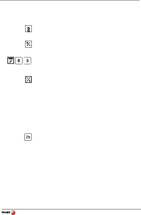
To get into and out of home search mode.
Selection of the current tool.
There are 20 tools that may be set for the part when using absolute coordinates. The possible reference points (datum points) are from 0 to 19. The 20i-T model shows the active reference on the display at all times, whereas the 30i-T model only shows it when it is selected, after pressing the reference key.
To select the axis or preset it with a certain value.
To zero the axis when the "quick zeroing" mode has been activated (see PAR11 in the installation manual).
Only at the 30i-T. Key to select whether the 2nd display corresponds to "Z1", "Z2" or to the "Z1+Z2" combination respectively. Every time this key is
pressed, the rightmost digit of the 3rd display rotates from "1" to "2" and off respectively.
To turn the display off while keeping track of the axes position at all times.
To cancel or abort an operation already initiated.
To validate a preset value or another operation.
Beginning of preset when the "quick zeroing" mode has been activated (see PAR11 in the installation manual).
To change the sign of the entered value or change from fine to coarse resolution and vice versa.
To access the special functions (Hold, taper calculation)
V0612 - 20i-T / 30i-T - Installation/Operation - DRO description - (3/32)

1.2 Turning the unit on and off
It turns on automatically when applying voltage or after pressing the on/off key.
It shows Fagor dro or the corresponding error code. See the error table and PAR11 for more options.
Turns the DRO on or off.
Precautions
Before disconnecting this unit from mains, press this key so it saves the current position.
If the unit is turned off or there is a power outage, the DRO will try to save the current position. If it does not have enough time to safe all the data, it will display ERROR 2 when turned back on.
(4/32) - DRO description - Installation/Operation - 20i-T / 30i-T - V0612
2 DRO operation
2.1 Display modes
MM / INCH conversion
To display the position of the axes either in millimeters or inches by pressing this key depending on whether the INCH led is off or on respectively.
Fine / coarse resolution
To turn off the last decimal digit (coarse resolution) for cases in which fine resolution is excessive, simply by pressing this key.
Number of decimals
This keystroke sequence accesses parameter PAR53. The first digit corresponds to the number of decimals to be displayed in mm and the second digit in inches.
Radius / Diameter
When these models are used for measuring radii or diameters, one can
display twice the real displacement of the axis (diameter) by pressing this key. The Φled will turn on or off to indicate the double or actual reading respectively.
Notes: - This works in this way if bit 2 of installation parameter PAR04 (radius/diameter) of the axis has been preset as “1” (commutated).
Z axis as a single axis or combination of both (Z1 and Z2). Only at the 30i-T:
To display the Z axis position, one or two feedback devices may be used. One for the cross slide (Z1)and the other one for the carriage (Z2).
When using two feedback devices, the "Z" axis display may show the position of Z1, that of Z2 or the result from combining (adding) the positions of both
axes.
The rightmost digit of the third display shows a "1", a "2" or is off to indicate
that the Z axis display (2nd one) corresponds to "Z1", "Z2" or to the combination of "Z1+Z2" respectively. This selection rotates by pressing this
key. It also shows the text "tool" followed by the number of the active tool corresponding to the XZ coordinates shown on the other displays.
Axis feedrate. Only at the 30i-T:
The third axis (Zs) display shows the feedrate of the fastest moving axis in m/min or feet/min depending on the status of the "inch" LED. To activate or cancel this option, see PAR11 in the installation manual.
V0612 - 20i-T / 30i-T - Installation/Operation - DRO operation - (5/32)

2.2 Incremental, absolute and with respect to Machine Reference Zero
This DRO shows the current position of two or three axes (20i-T / 30i-T).
Coordinate means the distance from one point or position with respect with another chosen as reference.
These DRO's can show the position of the axes in incremental or absolute mode.
•In Home mode, it displays the distance from the current position of the axis to the home point chosen in the feedback system.
Press this sequence to access the Home mode (only to search home).
(ABS) • In Absolute (ABS), when the ABS led is on , it displays the distance from the present position of the axis to part zero (D).
(I)• In Incremental, when the ABS and "home" LEDs are off the distance from the present position of the axis to the previous position is displayed.
Toggles between the ABS and incremental modes.
It could occur that the installation parameter PAR11(1) has been set to “0” for this key to independently affect each axis so that one axis can display its position in incremental mode while the other does this in absolute. In this case, to change the display mode, press one of these two sequences.
(6/32) - DRO operation - Installation/Operation - 20i-T / 30i-T - V0612

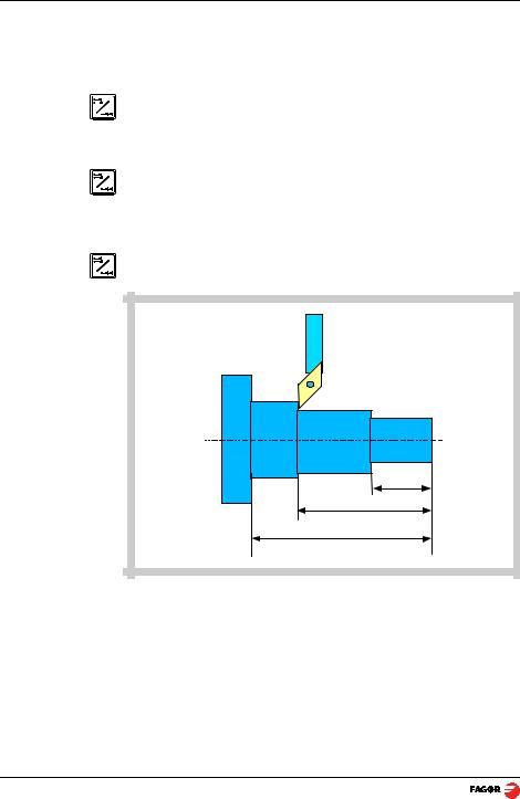
2.2.1Example
Using the lower figure, let us imagine we wish to make a part in which three holes have to be drilled with the coordinates stated. It is clear that the blueprint will only reflect the incremental coordinates (I) or the absolute ones (ABS) referring to the part zero (point "0" in the figure) although the DRO also shows them with respect to home (Io).
After referencing the axes, as was described in the previous section, we can make this part in incremental or absolute mode according to whether we chose a type of dimensions (I) or (ABS) of the blue-print.
In incremental mode:
|
|
|
|
|
|
|
|
|
|
|
|
|
|
|
|
|
|
|
|
|
|
|
|
|
|
|
|
|
|
|
|
|
|
|
|
|
|
|
|
|
|
|
|
|
|
|
|
|
|
|
|
|
|
|
|
|
|
|
|
|
|
|
|
|
|
|
|
|
|
|
|
|
|
|
|
|
|
|
|
|
|
|
|
|
|
|
|
|
|
|
|
|
|
|
|
|
|
|
|
|
|
|
|
|
|
|
|
|
|
|
|
|
|
|
|
|
|
|
|
|
|
|
|
|
|
|
|
|
|
|
|
|
|
|
|
|
|
|
|
|
|
|
|
|
|
|
|
|
|
|
|
|
|
|
|
|
|
|
|
|
|
|
|
|
|
|
|
|
|
|
|
|
|
|
|
|
|
|
|
|
|
|
|
|
|
|
|
|
|
|
|
|
|
|
|
|
|
|
|
|
|
|
|
|
|
|
|
|
|
|
|
|
|
|
|
|
|
|
|
|
|
|
|
|
|
|
|
|
|
|
|
|
|
|
|
|
|
|
|
|
|
|
|
|
|
|
|
|
|
|
|
|
|
|
|
|
|
|
|
|
|
|
|
|
|
|
|
|
|
|
|
|
|
|
|
|
|
|
|
|
|
|
|
|
|
|
|
|
|
|
|
|
|
|
|
|
|
|
|
|
|
|
|
|
|
|
|
|
|
|
|
|
|
|
|
|
|
|
|
|
|
|
|
|
|
|
|
|
|
|
|
|
|
|
|
|
25.000 |
|
|
|
22.600 |
|
|
|
|
|
|
|
|||||||||||||||||||
|
|
|
|
|
|
|
|
|
|
|
|
|
|
|
|
|
|
|
|
|
|
|
|
|
|||||||||||||||||||||
|
15.000 |
|
|
|
|
|
|
|
|
|
|
|
|
||||||||||||||||||||||||||||||||
|
|
|
|
|
|
|
|
|
|
|
|
|
|
|
|
|
|
|
|
|
|
|
|
|
|
|
|
|
|
|
|
|
|
|
|
|
|
|
|
|
|
|
|
|
|
-Press this key until the ABS LED is turned off.
-Move the axis up to the face of the part to set it as part zero.
At this point, one can proceed in two ways:
-Preset the axis with a zero value by pressing this keystroke sequence:
[22.600] -Move the axis towards the first position until the DRO reads: 22.600.
|
or... |
[22.600 |
-Preset the axis with a value of 22.600 by pressing this keystroke sequence. |
|
|
|
In case of a mistake, press this key to cancel it and leave it as it was. |
Pressing this key displays the previous preset value.
[0.000] - Move the axis towards the first position until the DRO reads: 0.000.
This last method turns out to be more practical as after selecting the destination coordinate one only has to remember to move the axis until the DRO reads zero.
V0612 - 20i-T / 30i-T - Installation/Operation - DRO operation - (7/32)
[25.000] [0.000]
Note:
ABS
-Once this turning operation has concluded, one can go to the next position, after having preset the next coordinate (25.000), by moving the axis until the display reads 0.000.
-And so on until all the turning operations are concluded.
By pressing this key until the ABS LED lights up, the DRO will show the real position of the axis with respect to part zero "0"
In absolute mode:
ABS
ABS
-Press this key until the ABS LED is turned on.
-To preset part zero:
-Place the axis exactly over “0” and press:
At any time, by pressing this key, the DRO will display the present position with respect with the previous zero (ABS led on).
22.600
47.600
63.600
(8/32) - DRO operation - Installation/Operation - 20i-T / 30i-T - V0612

2.3 Machine Reference selection and search
Although it is not absolutely necessary, it is recommended to use the reference marks (Io) of the feedback system in order to set a machine zero point.
This allows the user to reference the machine axes and restore the work coordinates after having turned the dro off, moved the machine while the dro was off, for safety or for any other reason.
Fagor linear encoders have reference marks every 50 mm all along its length.
In order to use these marks properly, choose an area on the axis, for example in the middle of the measuring length or at one end. Approach this area and carry out the home search. Once the reference mark has been found, mark this area with a marker or sticker in order to carry out the home search in the same area in later occasions and make sure that you are using the same machine zero point (home).
Fagor also offers encoders with distance-coded reference marks every 20, 40 or 100 mm. When using these distance-coded reference marks, there is no need to move to the 0 position to find the references, simply move a distance equal to the gap between marks (20, 40 or 100 mm depending on the linear encoder)
When using an absolute encoder, there is no need to search for the reference marks (home).
The dro stores in its internal memory work coordinates such as machine zero, absolute and incremental.
2.3.1Home search sequence
For encoders with regular reference marks, move the axis to the home area.
Access or exit the home search mode.
The axis displays blink showing " r " if the axis has not been homed or " r on" if it has been homed.
Select the axis to be referenced (homed)
The selected axis blinks until a reference mark is detected. The reference signal presets the axis display automatically with the value of PAR10, 0.000 mm by default.
If the encoder does not have a reference mark, move the axis to the desired position and press this key.
V0612 - 20i-T / 30i-T - Installation/Operation - DRO operation - (9/32)
2.4 Operation with tools
2.4.1Tool Preset
Up to 20 tools may be preset on this DRO model (from "tool 0" to "tool 19"). The unit stores in its internal memory the relative offsets of all the tools with respect to that of "T0".
Therefore, if "T0" has been preset in ABS mode (on X and Z) and, then, the rest of the tools, it will suffice to just preset "T0" again (on Z) to make a new part. The DRO will then automatically recalculate all the offsets of the rest of the tools without having to preset them for each part.
To preset a tool, just follow this procedure:
ABS |
- Place a part of known diameter in the chuck in absolute mode (ABS led on). |
|
- Move the tool to be preset until it touches the part.
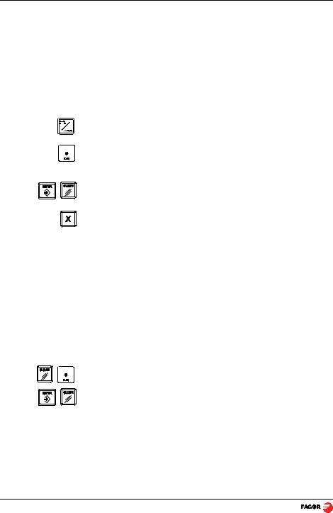
- Press this key. The 3rd display shows the word "tool" followed by the number of the active tool.
- Enter the tool number.
- Press [ENTER] to validate this operation or [C] to cancel it.
- Preset the part diameter.
These tool presets are kept in memory even when the unit is powered off up to a maximum of 10 years.
Notes: The presets done with any tool in incremental mode change the part zero for all the tools.
If a tool offset has been preset in Z1, Z2 or Zs mode, that tool must be used in the same mode (Z1, Z2 or Zs) when using it to machine the part.
The tool offsets are referred to the machine zero found at the time. When turning the DRO on, it is necessary to find the same reference mark.
The calculator function can also be used to preset an axis with the result of the calculation. See section 2.5.5 Calculator.
2.4.2Deleting all tool offsets
To delete the offsets of ALL the tools. Press this keystroke sequence: It will show the text: "Delete?",
Press [ENTER] to validate the operation or [C] to cancel it.
(10/32) - DRO operation - Installation/Operation - 20i-T / 30i-T - V0612
Loading...