


1N5819
1N5817 .... 1N5819
1 Amp. Schottky Barrier Rectifier
• Metal Silicon Junction, majority carrier conduction
• High current capability, low forward voltage drop
• Guardring for overvoltage protection
• Low power loss, high efficiency
• High surge capability
• Plastic material carries U/L recognition 94 V-O
• Terminals: Axial Leads
• Polarity: Colour band denotes cathode
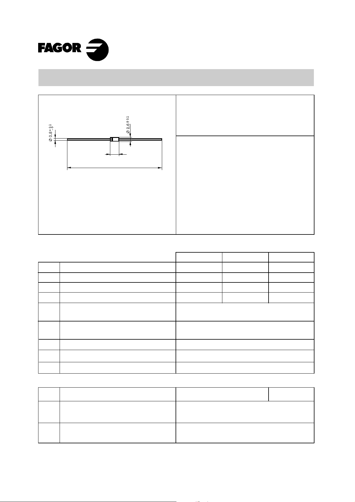
Mounting instructions
1. Min. distance from body to soldering point,
4 mm.
2. Max. solder temperature, 350 °C.
3. Max. soldering time, 3.5 sec.
4. Do not bend lead at a point closer than
2 mm. to the body.
Dimensions in mm.
Maximum Ratings, according to IEC publication No. 134
Peak recurrent reverse voltage (V)
Maximum RMS voltage (V)
Maximum DC blocking voltage (V)
Maximum non-repetitive peak reverse voltage (V)
Maximum average Forward current.
9.5 mm lead length at T
L
= 90 ºC
V
RRM
V
RMS
V
DC
V
RSM
I
F (AV)
T
j
T
stg
Operating temperature range
Storage temperature range
– 65 to + 125 °C
– 65 to + 125 °C
Electrical Characteristics at Tamb = 25 °C
V
F
Max. forward voltage drop at I
F
= 1.0 A
I
R
1 mA
10 mA
Max. Instantaneous reverse
current at V
RRM
I
FSM
8.3 ms. peak forward surge current
1N5817
20
(Jedec Method)
R
thj-a
R
thj-l
Typical Thermal Resistance 50 °C/W
15 °C/W
Voltage
20 V to 40 V
Current
1.0 A at 90 ºC.
Ta = 25 ºC
Ta = 100 ºC
14
20
24
1 A
1N5818
30
21
30
36
1N5819
40
28
40
48
25 A
DO-41
(Plastic)
58.5
± 0.5
5
+0.2
- 0
C
j
Typical junction capacitance at 1 MHz and -4V
DC
110 pF
0.55 V 0.60 V
NOTE: Thermal Resistance from junction to lead or to ambient PCB mounted with 9.5 mm lead length with 38x38 mm copper pads.
May - 00
 Loading...