


MSM400
Mobrey
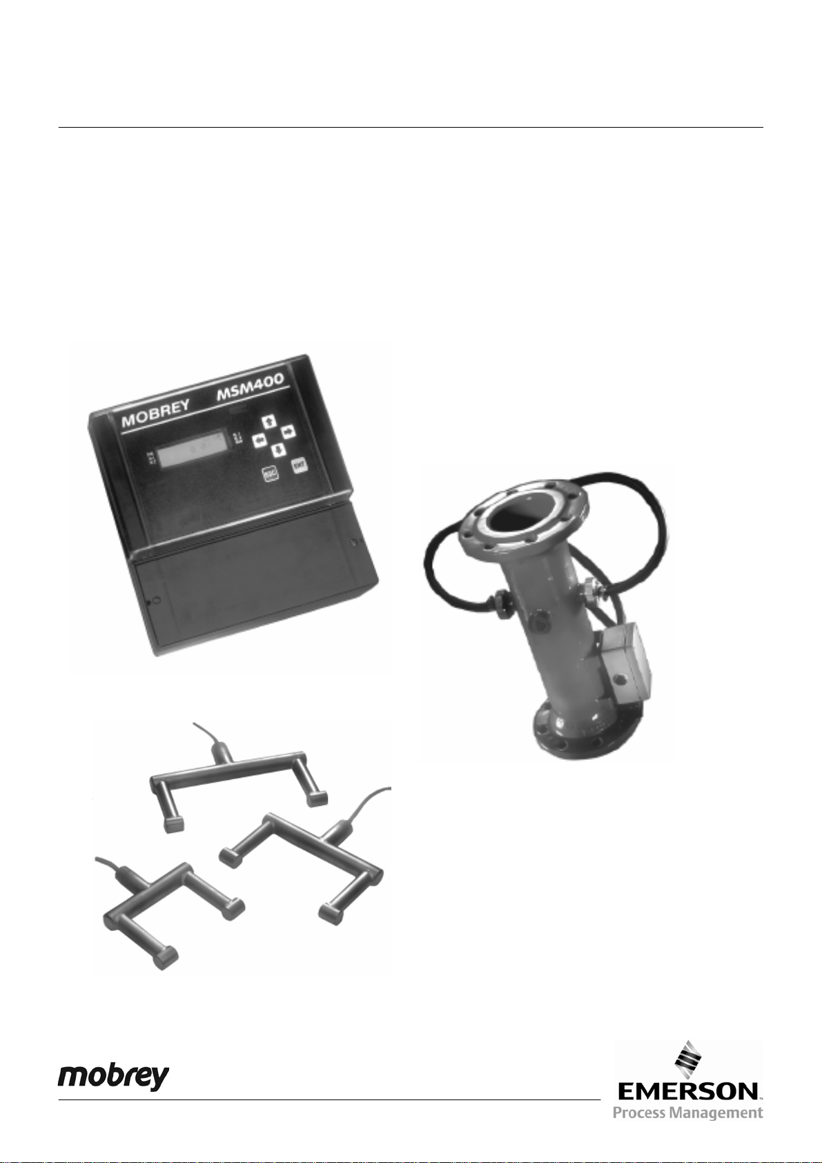
MSM400 Intelligent
Suspended Solids Monitor
Software Version 1.1
Level
Instruction Leaflet
IP258
November 2004
www.mobrey.com

IP258
2
CONTENTS
Page
1. PRODUCT INTRODUCTION 5
1.1 The MSM400 slurry monitoring system 5
1.2 Description 5
2. SENSOR TYPES
2.1 Safety Precautions 7
2.2 Hazardous Area systems 7
2.3 Quick Start guide 8
3. CONTROL UNITS 9
3.1 MSM400 Displays and Keypad 9
3.2 Specifications 10
4. INSTALLATION
4.1 Preliminary Checks 11
4.2 Pipe Section Installation 11
4.3 Suspended Sensor Installation 11
4.4 Sensor Cabling 12
4.5 Control Unit 12
4.6 Electrical Connections 13
5. PROGRAMMING
5.1 Programme Structure 16
5.2 Navigation in the Menu System 19
5.3 Diagnostic Parameters 18
5.4 Ex-Factory System Features 18
6. CALIBRATION
6.1 Zero Setting 18
6.2 Re checking Zero 19
6.3 Auto cal zero setting procedures 19
6.4 Auto cal span setting procedure 20
6.5 Auto cal lab values 21
6.6 Maximum % solids 22
6.7 Calibration - Alternative method 22
6.8 Zero setting procedure 22
6.9 Span Calibration Methods 22
6.10 Method 1-Slurry Type 22
6.11 Method 2-Sample Calibration 22
6.12 Method 3-Attenuation Value 23
7.0 PROGRAMMING THE MSM400 FUNCTIONS 24
7.1 Outputs 27
7.2 Current output 27
7,3 Relay Operation 27
7.4 Alarm 28
7.5 Display 28
7.6 Back Light 29
7.7 Engineering 29
7.8 System 29
8. HART SMART COMMUNICATIONS 30
9. MAINTENANCE / INSPECTION 30
APPENDICES
A1. Full Listing of Menu Structure 31-32
A2. Full List of Programme Parameter Functions 33-37
A3. HART and PSION Operating Instructions 38-40
D Handheld Communicator - Assembly Instructions 41-59
Footnote :-
In this manual the following terms are used which refer to trademarks from other manufacturers:
HART: is the protocol adopted for the MSM400 SMART Communications.
HART is a registered trademark of the HART Communications Foundation and is a mnemonic For
Highway Addressable Remote Transducer.
PSION: is the trade mark of PSION plc who manufacture the PSION ORGANISER Hand held computer.
The MOBREY SMART program is stored in a DATAPAK which is also a trademark of PSION plc, and is an accessory
for the Model LZ Organiser

IP258
3
Safety Precautions
The following safety precautions should be observed before using this product or working on the attached cables.
This MSM400 product is intended for use by qualified personnel who recognize shock hazards and are familiar with
the safety precautions required to avoid possible injury. Read the operating information carefully before using the
product.
The types of product users are:
Responsible body: This is the individual or group responsible for the use and maintenance of equipment, and for
ensuring that operators are adequately trained.
Operators use the product for its intended function. They do not require access to the electrical connections within
the control box, and would normally only operate the external keypad and monitor the display.
Maintenance personnel perform routine procedures on the product to keep it operating, for example, checking the
line voltage or checking electrical connections, replacing mains fuses etc.
Service personnel are trained to work on live circuits, and perform safe installations and repairs of products. Only
properly trained service personnel may perform installation and service procedures. However, the only serviceable part
in MSM400 is the mains cartridge fuse.
Users of this product must be protected from electric shock at all times. Product users must be trained to protect
themselves from the risk of electric shock.
Before operating the instrument, make sure the mains supply is connected to a properly grounded power supply.
Periodically inspect the connecting cables for possible wear, cracks, or breaks. Check lid and glands are tight, also
check unit for damage and if damaged do not use.
The fuse may only be replaced with same type and rating for continued protection against fire hazard.
To clean the instrument, use a damp cloth or mild, water based cleaner. Clean the exterior of the instrument only. Do
not allow liquids to enter or spill on the instrument.
WARNING - If this equipment is used in a manner not specified by Mobrey Measurement, the protection provided
may be impaired. The MSM400 is regarded as permanently installed equipment and as such a double pole supply
isolating switch or circuit breaker must be included in the installation. This should be in close proximity to and not
be obstructed by the equipment. It should be marked as its disconnecting device.
A protective earth must be used for all applications.
The installation of the MSM400 and its associated power cables must be such that tank overflow, local flooding or
pump failure do not cause these to be submerged or subject to flows of water. Sensors and sensor cabling can be
submerged without hazard to equipment operators when correctly connected as described in this manual.
CHECK THAT THE POWER SUPPLY IS SUITABLE BEFORE SWITCHING POWER ON.
Internal adjustments can select mains 115 Volts AC power, which makes the equipment unsuitable for 230V AC
supplies. Check this Voltage selection switch compared to the available power supply.
Explanation of symbols:
The Protective earth terminal must be connected to an external Protective earthing system.
Refer to manual.
!
Hazardous area systems :-
Where the MSM400 is connected to sensors located in an explosive atmosphere additional instructions apply.
Refer to Safety Instructions IP258/SI
IP258
4
QUICK START
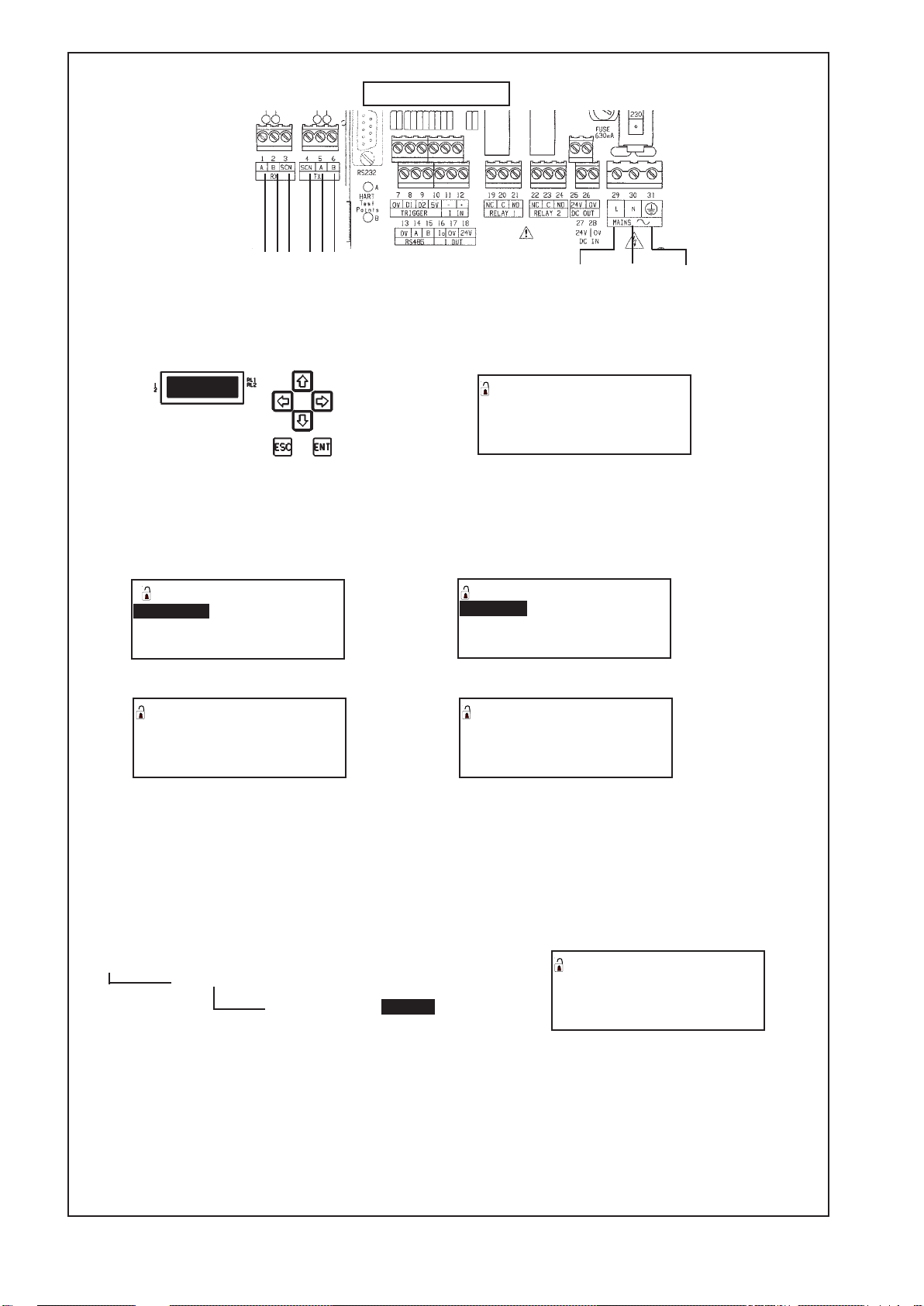
1) Connect the mains supply to the terminal connections L, N and E as shown above.
2) Connect the sensor to the terminals as shown above.
3) With power on, press a button on the key pad as shown below. This will access the main menu.
4) Navigation around the menu system is achieved by using the up and down arrow keys to highlight an option and
the ENT key to accesss the various levels. Pressing ESC returns the user to the previous level.
Highlight toggle run and press ENT. PRESS ENT AGAIN to open the toggle run padlock. Press ESC to return to
main menu. Parameters may now be altered.
5) To calibrate the unit, highlight CALIBRATION and press ENT.
6) Now highlight AUTOCAL and press ENT.
7) Highlight SETZERO and press ENT
8) Follow the instruction then wait a few seconds.
9) When ENT is pressed the zero is set. Press ESC four times to return to normal display.
10 ) Follow the same procedure to set the span. i.e. Highlight SETSPAN in the AUTOCAL menu and press ENT.
Up to 3 SPAN values can be taken. Press down arrow to access next span.
11 ) When setting span, sludge samples should be taken for analysis. The results of the samples are the input to the
control unit for reference in THE LABVALUES menu.
INPUTTING A VALUE
1) Access the parameter as shown below :
CALIBRATION - Manual/Entry
AUTOCAL - SETZERO
SETSPAN
LAB VALUES - LabVal 1 ------------------
LabVal 2
LabVal 3
2) To input a value press the right arrow to highlight the correct digit to be altered. The value of the digit is then
incremented or decremented by using the up or down arrows. To save a value press ENT. 'ESC to return to menu'
3) Now input your expected max % solids required. Located in - Calibration - AUTOCAL - Max %. (See section 6 for
details)
4) All other parameters are setup in a simpler way and can be located by looking at the full menu structure in
Appendix 1 of this manual.
5) For outputs to be made active Toggle run padlock must be closed.
Note: Press and hold ESC to return to the main menu form any where in the menu structure. Press ESC once more
to return to normal display. Once a parameter is reached (indicated by P*** or D*** on the display) all other
parameters can be reached by simply scrolling using the up or down arrows.
MAIN MENU 0
TOGGLE RUN 0
CALIBRA TION
SETUP
DISPLAY
SET ZERO 0
In clear liquor
Press 0
SET ZERO 0
In clear liquor 0
press ENT to set
16.2 dB 25.3 dB
AUTOCAL 0
SETZERO MAX % 0
SETSP AN
LAB V ALUES
0
LabVal 1 % 0
0.00 P150
-------------Signals from sensor
L IVE NEUTRAL EARTH
MAINS IN
SENSOR CONNECTION
Terminal connections
White
Black
Green
White
Black
Green
CALIBRA TION 0
AUTOCAL 0
MANUAL ENTR Y
MAX %
ENT
ENT
ENT
IP258
5
1.0 PRODUCT INTRODUCTION
1.1 THE MSM400 SLURRY MONITORING SYSTEM
The MSM400 is an advanced Microprocessor based, HART compatible, versatile slurry measurement system, with a
wide range of built-in display, control and alarm function options. The Menu driven programming is simple to use,
and allows complete configuration of the unit from the external membrane keypad. Sensor and electrical connections
are in a separated terminal housing.
This manual is for Software Version 1.1
1.2 PRODUCT DESCRIPTION
The Mobrey MSM400 is a microprocessor based electronic control unit. It operates with sensors mounted in a pipe
section or suspended in a tank. The MSM400 monitors the suspended solids concentration in the liquid between
the two sensor faces. The normal application is to monitor this percentage, typically in the range 0.5% to 15%, to
provide signals for a plant control system to operate the slurry transport process. Typically this might be to desludge a
sewage settlement tank, or in mineral processing to maintain the percent solids of china clay, or similar, moving on to
further refiners.
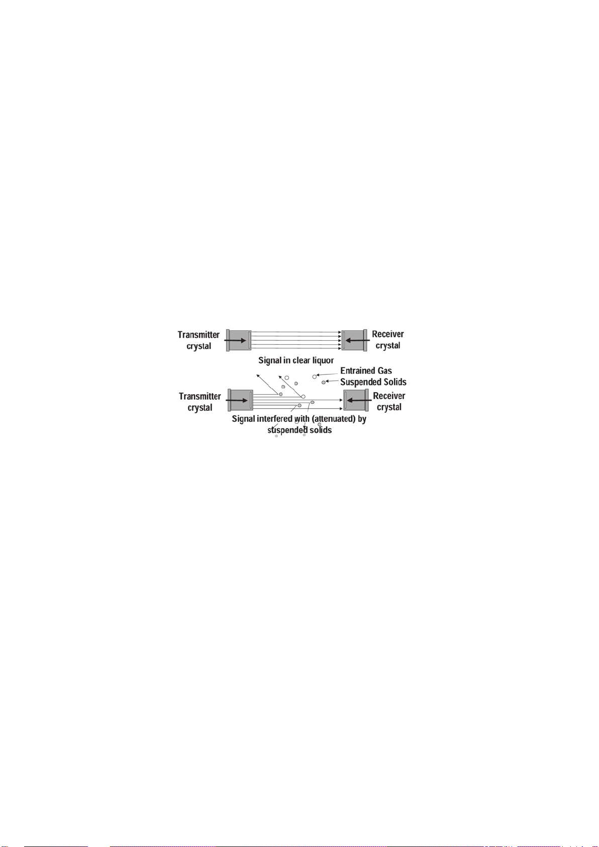
The technique used to measure suspended solids is ultrasonic attenuation. As suspended solids pass between the
gap in the sensor faces they scatter the ultrasound. The amount of signal that the sensor receives is inversly
proportional to the % of suspended solids.
To allow accurate measurement over a wide range of % solids the attenuation is measured at 2 different frequencies.
Control signals :
The MSM400 has a 4-20mA, 2 relays and analogue output, typically 4-20mA, The MSM400 can control a desludge
operation using a combination of measured % solids, external trigger and internal timers.
The unit is also HART compatible, to feed in to digital control systems using HART protocol.
A typical application would be with the sensors mounted in a discharge line from a refiner or settlement tank. The
relay in the MSM400 would be used to stop the de-sludge cycle when the liquor runs clear, switching at typically
about 4-5% suspended solids.The ultrasonic technique has an advantage over some techniques in that it is largely
unaffected by fouling of the sensor face.

IP258
6
The relationship between attenuation and suspended solids is
shown graphically in Figure 2. Calibration of the unit involves
adjustment of the zero point, by setting up the sensors in
clean liquid (supernatant), and then setting the slope of the
straight line graph, either according to past data or from site
samples.
In the memory of the MSM400 there is information on various
slurry types, to enable simple initial set-up. More accurate
adjustment can then be made once site samples have been
taken.
Zero Ref
Attenuation
(dB)
S
l
o
p
e
% Solids
Figure 2 : Ultrasonic Attenuation versus
Suspended solids
SLURRY CHARACTERISTICS
The relationship between the measurement of ultrasonic attenuation and the percentage solids of a particular slurry
type is dependent on the density of the slurry particles and their average size distribution. This is known from
experience for most slurry types, and is expressed as a number, which is the ultrasonic attenuation in deciBels (dB),
per mm gap between sensor faces, per one percent suspended solids.
Calibration:
The Mobrey experience with using ultrasonics for suspended solids monitoring has been developed over 25 years.
Calibration systems for the MSM400 use this experience, allowing the plant operator to choose whether to set up the
unit based on Mobrey site and slurry experience, or whether to take site samples to fine tune that data to suit the
specific site conditions. The MSM400 is versatile enough to allow simple or complex calibrations.
IP258
7
20
61
102
30
30
22
Standard gap = 150mm
Specify gap
50 to 450mm
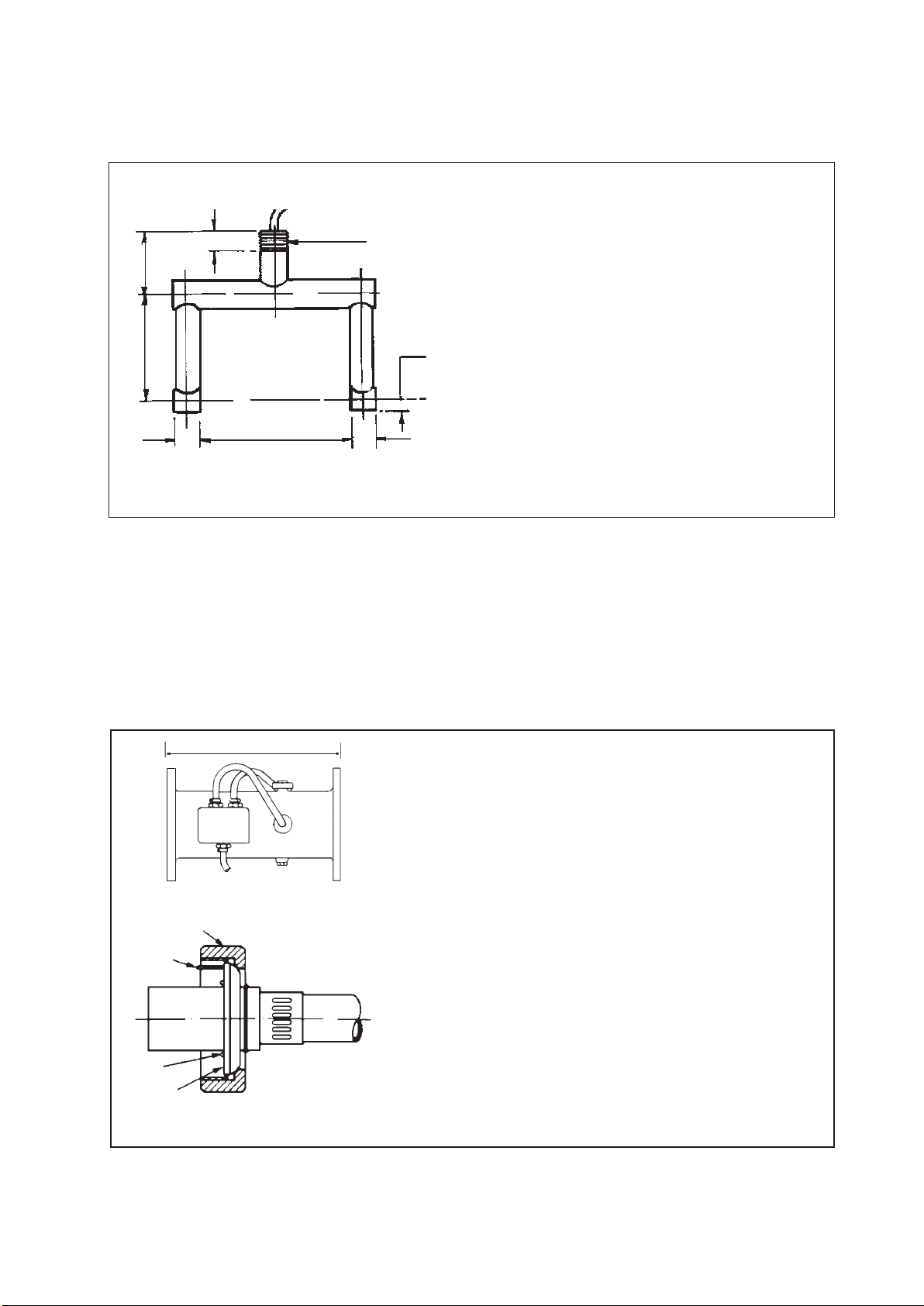
2.2 MOBREY PIPE SECTION SENSORS
The Mobrey pipe section is used as part of a pipeline transporting the slurry to be monitored. Each pipe section
contains two sensors, installed with their faces accurately aligned and flush with the pipe inner wall, to avoid any
excessive slurry or grease build up on the faces.
Figure 4 : MSM448 Pipe Section Sensors
455
'O' ring
Sealing
face
Location pin
Retaining nut
R¾" (BS21:1973)
¾" BSPT
Material : 316 Stainless steel
Gap size : 100mm, 150mm, 200mm,
300mm, 450mm
(others on request)
Cable : Dual twin-axial
Max. Pressure : 105 kg/cm2 (103 bar)
Temperature range : -40°C to + 70°C (others on
request) Refer to Sensor
safety data for intrinsically
safe systems
Malleable cast iron epoxy coated
316 stainless steel
1" NPT
In line installation
DN100, DN150, DN200 to BS4772
(others on request)
10 Bar (PN10)
-40°C to +70°C(for T6), +120°(for T5)
(Others on request)
Refer to Sensor safety data for intrinsically
safe systems
Oil hose protected on pipe section,
Screened twisted pair
7m dual twin-axial from junction box (others
on request)
IP65 aluminium alloy
Material pipe section :
Material sensors :
Drain fitting :
Mounting connection :
Flanges :
Max pressure :
Temperature range :
Sensor cable :
Cable length :
Cable junction box :
2.0 SENSOR TYPES
2.1 SUSPENDED SENSOR TYPE MSM433
Figure 3 : MSM433 Sensor and Specifications

IP258
8
2.3 SENSOR TYPE NUMBERING SYSTEM
MSM *** * *** * * / *
No. - Indicates special requirement
i.e. 1 - with PN16 flanges
7 - 7m cable supplied as standard
D - Customer defined upto 100m (must be
clearly stated on order
V - Spray valve (pipe section only)
P - No spray valve (pipe section only)
T - 433 tank mount
000 - Sensor size i.e. 100, 150, 300, 450mm as standard
for tank mount
100, 200, 150mm as standard for pipe section sensor
(others on request)
A - Intrinsically safe (ATEX)
N - Non Intrinsically safe
433 - Sludge blanket tank mount sensor
448 - Sludge pipe mount sensor
In intrinsically safe systems, the maximum length of integral cable permitted by the sensor certification is 50m.
Additional extension cables are however permitted.
IP258
9
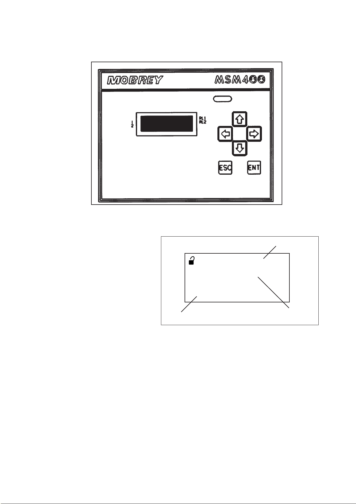
The MSM400 is wall mounted: the lower
section of the housing is for cable connections,
and the upper part has the 4 line LCD and
keypad controls. The whole unit is IP65.
Typically the display will show as in Figure 7,
the top line shows whether the programme lock
is open together with the time display. The
actual value is displayed in the centre. The
attenuation figure in decibels is on the bottom
line.
Figure 6 : Typical MSM400 liquid crystal display
Additional flags on the display show the status of the two relay outputs, RL1 and RL2 ,and of the digital control
inputs into the MSM400.
KEYPAD OPERATION :
There are 6 buttons on the MSM400 front panel, the four ARROWS allow navigation around the programming menu
and the " ESC" and "ENT" buttons allow movement from one screen to the next. By pressing "ESC" repeatedly, the
screen will always return to the normal display as shown in Fig 7. Movement through the menu structure using the
arrows is shown by the titles being "highlighted", ie reversed to showing white letters on a black background. The LCD
is backlit for operator convenience. (This can be turned off if required).
Figure 5 : MSM400 keypad and LCD display
3.0 CONTROL UNIT
3.1 MSM400 DISPLAYS AND KEYPAD
RL2
RL1
03.09 0
4.6 %
46.3dB
1
2
Display 1
Display 2Display 3

IP258
10
3.2 SPECIFICATIONS--MSM400
Housing ABS with polycarbonate lid, IP65
External dimensions 256.5 wide, 236.7 high, 95.0 deep, including wall mounting brackets
Cable Glands 3x 16mm holes and plastic glands supplied
3x 20mm holes and plastic glands supplied
Weight 2 kg
Wall Mounting holes 6 off Diam 5.0mm (See Drawing Section 4.5)
Power supply options 115 V a.c. (±15%) 50 / 60 Hz
230 V a.c. (±15%) 50 / 60 Hz
or 24 V d.c. (15 to 30 Volts)
Power consumption a.c. 10VA
d.c. 6W
Fuse (F1) 200 mA (T) 5 x 20mm
Current Output 0-20 or 4-20 mA selectable,
maximum load 1KΩ (at 22mA)
maximum applied voltage 48v d.c
HART HART digital communications, Two HART internal test terminals provided.
Relay Outputs 2x SPCO Relays, rated 5 Amps at 250 V a.c. Resistive
DC Power Output 24V DC for external sensors such as Mobrey Electrosensor
Sensor connections Terminals for Mobrey sensor Tx and Rx cables, each 2 cores and screen
Trigger inputs Unit accepts two 5V d.c.trigger input signals. 5V d.c. provided - compatible
with Mobrey Electrosensor
Terminals Max. cable size 2.5mm
2
Ambient temperature -30°C to 55°C
Max Altitude 2000m
Max Humidity 95% RH
Electrical Safety Conforms to EN61010-1
Installation Category Cat III 132V a.c. Max., Cat II 264V a.c. Max.
Pollution Degree 2
EMC Complies with EN61326 (Industrial level)
IP258
11
4 INSTALLATION
4.1 PRELIMINARY CHECKS
The MSM400 system is normally supplied in two packages, one for the MSM400 Control Unit and one for the
sensor, whether it is a pipe section or a tank sensor. Take care in handling the pipe section. In particular do not
damage the cable or the hose protection for the cable where it enters the sensors. Before installation check that
there has been no damage in transit, particularly to the sensor cables. Check that the equipment is as specified, and
that the pipe section length and flanges are compatible with plant pipework.
Sensors in intrinsically safe systems may be mounted in potentially explosive areas ("hazardous areas"). Refer to the
sensor safety data section 2.4.
The control unit must be mounted in a non-hazardous ("safe") area. Refer to control unit safety data section 3.3.
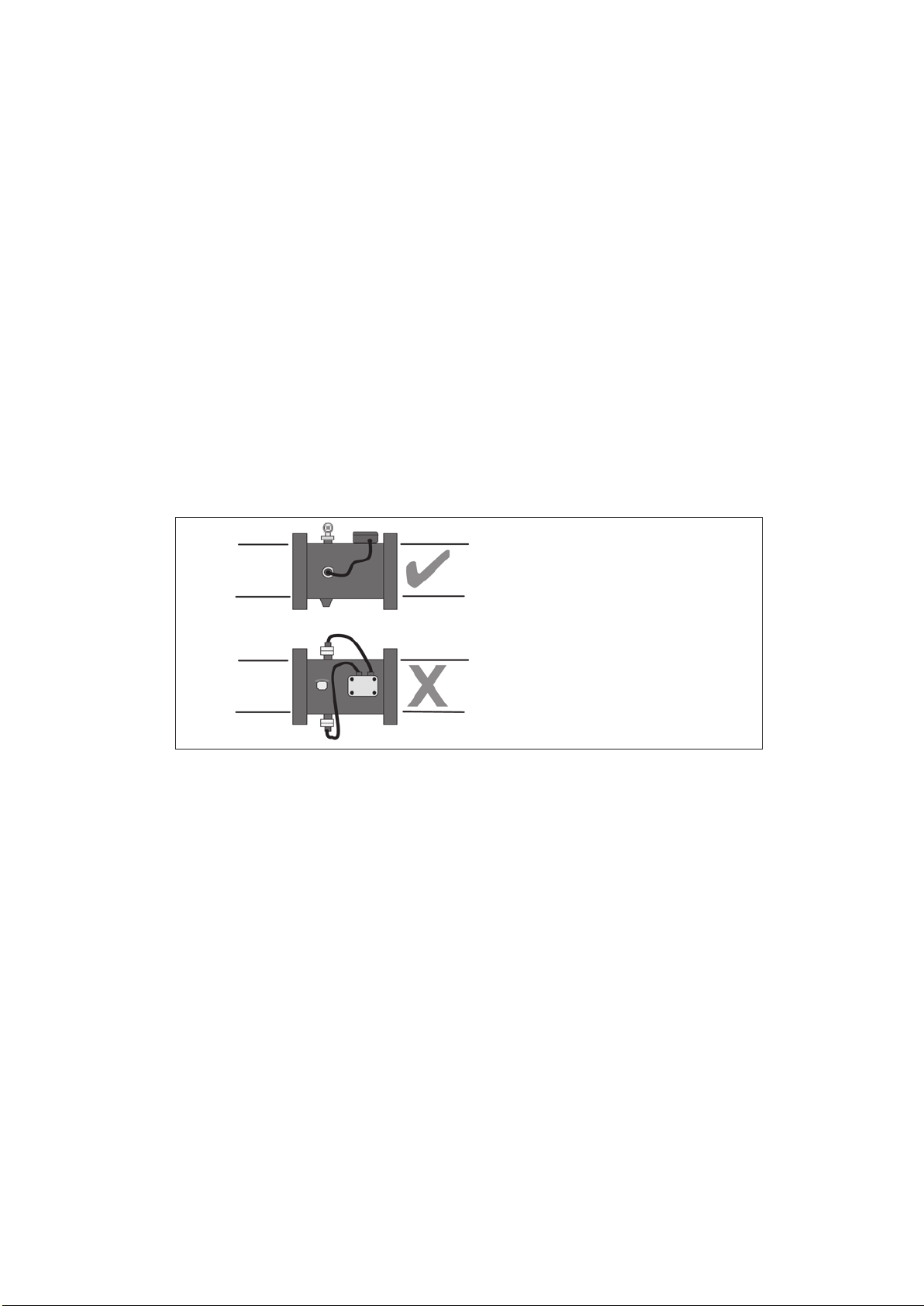
4.2 PIPE SECTION INSTALLATION
The Mobrey MSM448 pipe section sensor should be same size as surrounding pipe work. It should be installed in a
straight section of line, if possible, with the sensors in a horizontal plane. This avoids the sensors being covered with
debris at the bottom of the pipe, and being in an air gap at the top of the pipe. Particular attention must be paid to
the positioning of the pipe section in relation to pressure reduction or agitation of the slurry to be monitored :
Figure 7 : Pipe sensor orientation
WARNING:
Air or gas that comes out of suspension in a slurry gives a high ultrasonic attenuation, giving a false high solids
reading. The installation must maintain the full hydrostatic pressure in the slurry up to the pipe measurement
section. Any unnecessary pressure reduction should be avoided. This means avoid free fall of the slurry into a sump,
avoid pumps and partly open valves, avoid abrupt changes of pipeline diameter upstream of the sensor pipe section
installation point. If possible position the sensors directly at the outlet of the tank, low down, so that the full
hydrostatic head is maintained on the monitored liquid. However, it may be necessary to remove the sensors for face
cleaning later, so isolation valves are desirable. The Mobrey Sensor pipe is supplied with a flushing spray nozzle,
which directs a supply of water at the sensor faces. This is a useful cleaning procedure, avoiding the need to remove
the sensors from the pipe. A water supply is required, connected to the purge nozzle on the top of the sensor pipe
section.
4.3 SUSPENDED SENSOR INSTALLATION
The Mobrey MSM433 sensor is available with the gap between sensor faces from 100 mm up to 450 mm, for higher
sensitivity to light slurries. These sensors are usually mounted directly into the settlement tank, at pre-selected levels
above the tank discharge outlet. Mounting can be vertically down on a piece of conduit, or suspended on the sensor
cable. Whilst the conduit might be attached to the tank wall, it is normal to have the sensor well away from the wall
itself, to avoid any non moving slurry or "dead" settlement areas. It should be possible to lift the sensor out for
periodic cleaning and/or rag removal.
Pipe line
Pipe line
Sensors horizontal in pipe OK
Sensors vertical in pipe NOT OK
Sludge settles on bottom sensor
Top sensor probably in air
IP258
12
4.4 SENSOR CABLES
The ultrasonic drive signals on the sensor cables are normally at 1MHz and 3.3MHz. The cables are a special
construction of two separately screened twisted pairs, designed to meet electromagnetic compatibility regulations.
The cables can be extended up to 100 metres, but should use the same cable type, available from Mobrey
Measurement. (or consult factory for alternative vendors). The certification for intrinsically safe systems requires that
cable joins should be in enclosures rated at least IP20 and suitable for the intended enviornment and that the wiring
should withstand a test voltage of 500V rms to earth. The electrical parameters of the cable used must conform to
Table 1 in section 2.4.
Twisting the cables on installation should be avoided. Cable runs should be separated from any high voltage or mains
cables, to avoid crosstalk or switching transients.
4.5 CONTROL UNIT
The control unit housing is rated IP65. It is suitable for mounting outside, but this should be above any flood level,
away from any overflow water path, and away from direct sunlight. Internal sensors turn the LCD backlight off if the
temperature is excessive.
The control unit must not be mounted in areas where an explosion hazard exists.
It is not necessary or advisable to remove the lid to the upper part of the box, containing the LCD and keypad.There
are no user serviceable parts inside. The control unit must not be modifed in any way. The keypad and LCD are
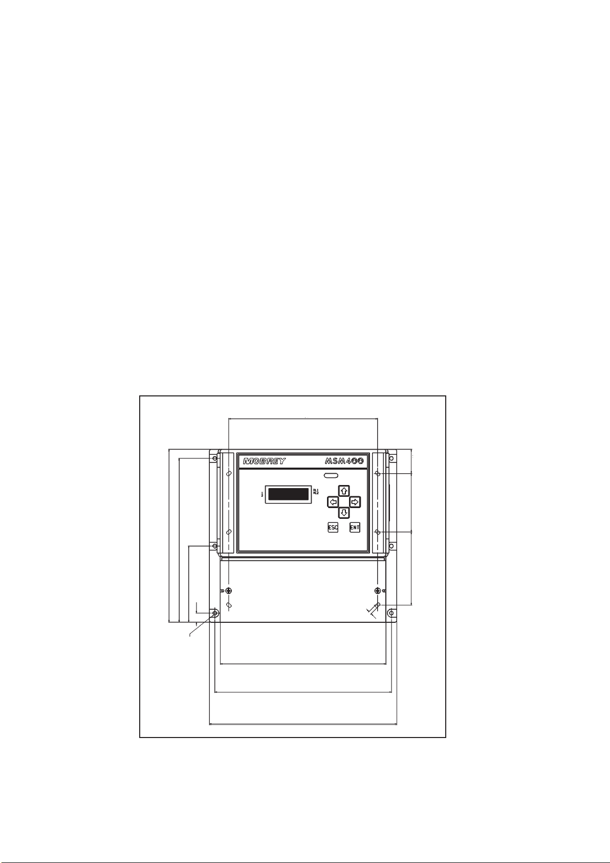
linked to the lower electronic pcb by a ribbon cable at the left hand side of the upper housing. Mounting brackets
for wall mounting are provided, and these should be attached to the rear of the housing using the self tapping screws
(also provided).The brackets are then used to wall mount the MSM400, using the six mounting holes available.
Dimensional information is shown below:
203.5
Internal wall mounting holes
33.35
80.0
4.2
226.5
241.5
256.5
6 off mounting holes Ø
5.0
12.5
104.2
224.2
236.7
100.0
Figure 8 : MSM 400 Control Unit Dimensions
Note that the weight of the MSM400 is 2Kg. To conform with safety requirements the wall should be capable of
supporting 4 x this weight, ie. 8Kg. 5mm diameter steel screws should be used.
IP258
13
4.6 ELECTRICAL CONNECTIONS
All field wiring connections are accessible by removing the lower lid, which is secured by two screws. Note that it is
the responsibility of the installer to observe all local regulations and approval requirements, and to use cable to suit
the environmental requirements of the particular application. Obtain and check any hazardous area work permits
required before applying power to the MSM400.
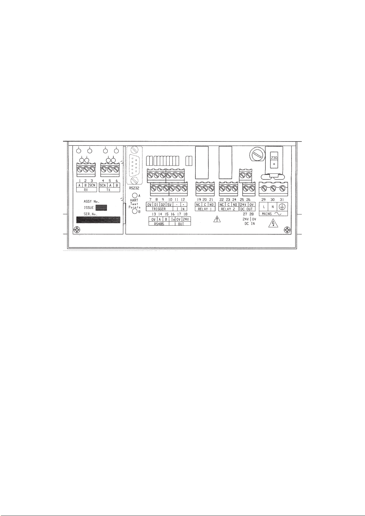
The diagram below shows the layout of external connection terminals: all terminal blocks are suitable for wires
0.5mm
2
to 2.5mm
2
(26-12 AWG). Insulation should be stripped back 7mm.
Ensure wiring is suitable for the load current and the insulation is suitable for the voltage, temperature and
environment of the installation.
Note that in intrinsically safe systems, apparatus connected to the MSM400 must not be supplied from a voltage
greater than 250V rms or 250V DC.
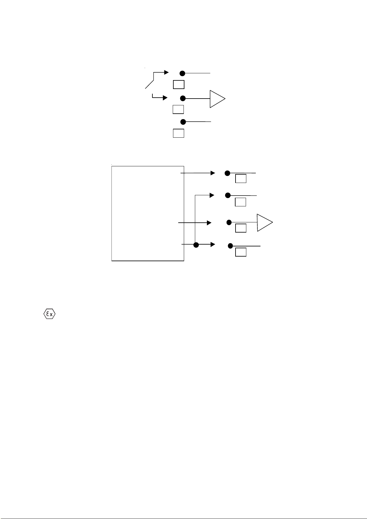
Figure 9: Connection Terminal Layout
Note that not all of the labelled terminals are functional in this version of the MSM400. The functions available are
listed below :
CONNECTION DESCRIPTIONS :
Terminal Label Function
1 RX A Sensor Cable
2 RX B Sensor Cable
3 RX SCN Screen for 1+2
4 TX SCN Screen for 5+6
5 TX A Sensor Cable
6 TX B Sensor Cable
7 TRIGGER 0V Ground ref for Trigger inputs
8 TRIGGER D1 Digital input No 1
10 TRIGGER 5V 5 V output
16 I out Io Current output (4-20mA)
17 I out 0V Current output zero ref terminal
18 I out 24V Current output 24 V DC loop power : refer to Fig. 10
19-21 RELAY 1 NC-C-NO Relay output terminals for Relay 1
22-24 RELAY 2 NC-C-NO Relay output terminals for Relay 2
25 DC out 24V Output of 24 VDC for powering external devices.
26 DC out 0V Ref for DC output
27 DC in 24V Positive supply at 24VDC to the MSM400--ie DC power input
28 DC in 0V Ref terminal for DC supply input
29 Mains L AC power input 115/230V, Live terminal NB: SELECT 115 or 230V
30 Mains N AC power input 115/230V, Neural terminal ON SWITCH ABOVE
31 Mains E Protective Earth (PE) THESE TERMINALS
NOTE 1 The sensors are symmetrical, so either of the two cable pairs can be chosen as "Tx" or "Rx
K7941
FUSE
200mA
IP258
14
SENSOR CONNECTIONS
The sensor connections are on the left side of the terminal enclosure.
Each sensor has two screened twisted wire pairs, either as one dual pair cable, or two separate pairs
One pair is connected to the TX (transmit) group and the other to the RX (receive) group. The sensors are
symmetrical so either of the pairs can be chosen as TX or RX. The two cores in each group are connected to A and
B, the polarity is not important. Each screen connection, normally coloured green, is connected to the group’s SCN
terminal. Cable screens must not be earthed at any other point.
The un-screened length of the cores should be as short as possible, to prevent crosstalk, but in any case no longer
than 30mm.
RELAYS
The relay NC-C-NO labels represent the relay terminals in the de-energised state.
HART CONNECTIONS AND JUMPER SETTINGS
There are two clearly labelled HART Test Points, labelled A and B. These test points are for connection of a HART
Hand Held Communicator, to provide a local interface to the MSM400 if required. Above terminal blocks 7-12 there
is a plug selector labelled PL1.
The normal position is with the plug shorting out the left hand pins. In this case, the external 20 mA loop must have
at least a 250 ohm impedance to enable HART communictions. With the plug in the central position, the MSM400
itself provides this load in the 20 mA loop. The right hand position enables HART communication when there is no
external loop connected by connecting a 270 ohm resistor across the current output. (See Appendix D).
NOTE:
The 20 mA output will not function correctly when the link is in this right hand position, so replace it in position 1 or
2 after use!
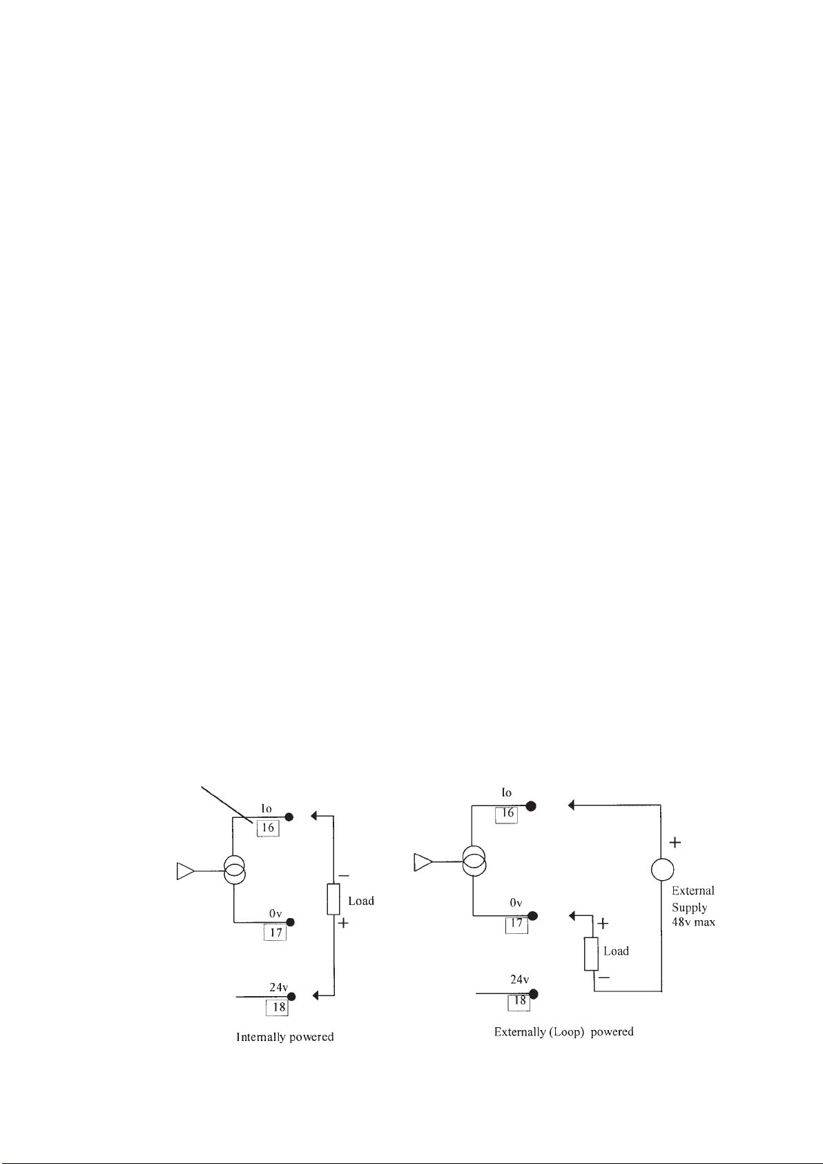
CURRENT OUTPUT
The current output may be connected in loop-powered mode or internally powered mode.
See connections in Fig 10 below.
In Loop-powered mode an external power source is required. A minimum of 2.5v is required across terminals 16 and
17 for correct operation. The external voltage should not be more than 30v.
Note that the current output must not be routed through hazardous areas unless protected by an additional I.S.
barrier.
Terminal Number
Figure 10 : Alternative current output configurations
IP258
15
TRIGGER INPUTS
There is trigger input D1. This can be used to control desludge and other functions see programming section. The
digital trigger input is connected as shown below:
A voltage greater than 2V on Terminal 8 (D1) causes trigger input 1 to be active. This can be achieved by
connecting to terminal 10 (5V) via an external switch or relay. The maximum voltage should not exceed
28V.
The trigger input is also compatible with the MOBREY Electrosensor sensors and head amplifiers. A 24V output is
provided for this purpose. Typically this allows complete control of the desludge cycle by using a second sensor
(Electrosensor) to start or stop the cycle. The terminal connections are shown above (note: it is important that the two
0V connections on terminals 7 and 26 are linked).
NOTE : When connected to these terminals the electrosensor sensors and head amplifiers MUST NOT be
installed in explosive atmospheres.
MAINS SUPPLY
The unit can be powered either by 24V DC or by mains AC power. If both are connected, the unit will select the
supply producing the highest internal 24V power rail. Select the AC Voltage as 115V or 230V using the selector slide
switch above the AC line terminals.
Although the MSM400 meets all European standards for surge immunity on power and signal lines, it is
recommended that lightning suppressors are fitted if local conditions make this advisable. Units manufactured by
Telematic are suitable.
SAFETY PRECAUTIONS
A switch or circuit breaker should be installed in close proximity to the instrument, and labelled as such.
The unit must be earthed using the protective earth terminal 31.
INITIAL POWER UP
The unit will initially display the software revision number on Power up, and then revert to the standard display
screen, showing a measured slurry/sludge density. If the sensor is in air, then this value will be high -the unit is
effectively at full scale deflection.
24V
0V
D1
0V
25
24V
MES*AI OR
ELECTRO SENSOR
0V
26
8
7
5V
D1
0V
10
8
7

IP258
16
5.0 PROGRAMMING
5.1 The operation of the MSM400 is controlled by means of programmable parameters. These are stored in
memory and may be set by the user to define variables such as calibration scale factors, set points, and modes of
operation. The parameters are accessed using the keypad, by means of a menu system as shown below. (Parameters
may also be edited remotely using the HART protocol. See Appendix N). For a full listing of the menu structure refer
to Appendix A1.
5.2 Navigation in the menu system
From the main display, pressing any key except ESC will enter the menu system. The top level menu contains the list
of available menu items:
TOGGLE RUN
CALIBRATION
SETUP
MONITOR
To move up and down the list, use the UP and DOWN arrows until the required menu item is highlighted, then use
the ENT or RIGHT arrow key to select it. The presence of additional menu items off the screen is indicated by up
and down arrows on the right hand side of the display
The next level of the menu is then displayed and the required option can again be selected as above.
Continue until the required parameter is displayed and select it using the ENT key. (Note that menu groups are in
upper case letters, parameters are in upper and lower case.)
The parameter may now be modified. Numeric values are edited one digit at a time, the LEFT and RIGHT arrows
select each digit by highlighting them and the UP and DOWN arrows increment and decrement each digit. Some
parameters e.g. “PV Units” are in the form of a list. These are edited in a similar way, selecting with the RIGHT arrow
and using the UP and DOWN arrows to scroll through the list
When the displayed value is correct, press the ENT key to store it.
Scrolling
When a parameter is displayed but no digit is selected, the UP and DOWN arrow keys will scroll to the next parameter
in numeric order. This provides an alternative method of accessing parameters without using the menu facility.
Example: Relay 1 set point programming.
To programme the relay, follow the simple steps shown below;
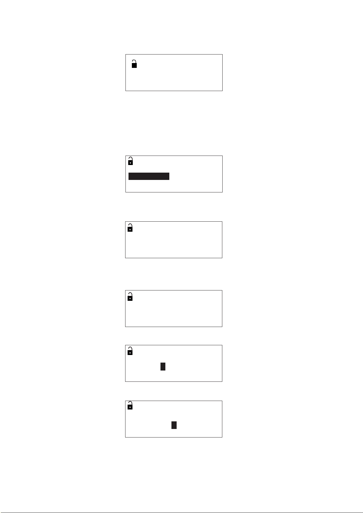
1. To alter any menu option the padlock icon in the top left of the display must be open. This is done using the
TOGGLE RUN menu.
2. To access TOGGLE RUN from the normal display, press any key except ESC to display the main menu. The
down arrow (↓) shown on the screen indicates that there are further options. (including MONITOR)
MAIN MENU 0
TOGGLE RUN 0
CALIBRATION ↓
SETUP
IP258
17
3. Use the down arrow key (ß) to highlight the TOGGLE RUN option and select it using the “ENT” key. The
TOGGLE RUN screen is then displayed:
TOGGLE RUN 0
0
4. To open (or close) the padlock press ENT as required. Press ESC to return to the main menu.
5. Programming is now enabled.
6. From the Main Menu screen, use the down arrow key (ß) to highlight the SETUP option and select it using
the “ENT” key
7. In the SETUP menu use the ß key to highlight the OUTPUT option and select it.
8. In the OUTPUT menu use the ß key to highlight the RELAY option and select it.
9. The parameters associated with the relays are now shown.
10. In the RELAY menu highlight the RELAY 1 MODE and select it using the “ENT” key.
0
Relay 1 Mode 0
Set Point P410
11. Press the right key (Þ) to highlight the option.
0
Relay 1 Mode 0
Set Point P410
12. Note; with the option highlighted pressing the up and down arrows scrolls through the available options.
13. With the set point option highlighted press ENT to select. The highlighting now disappears.
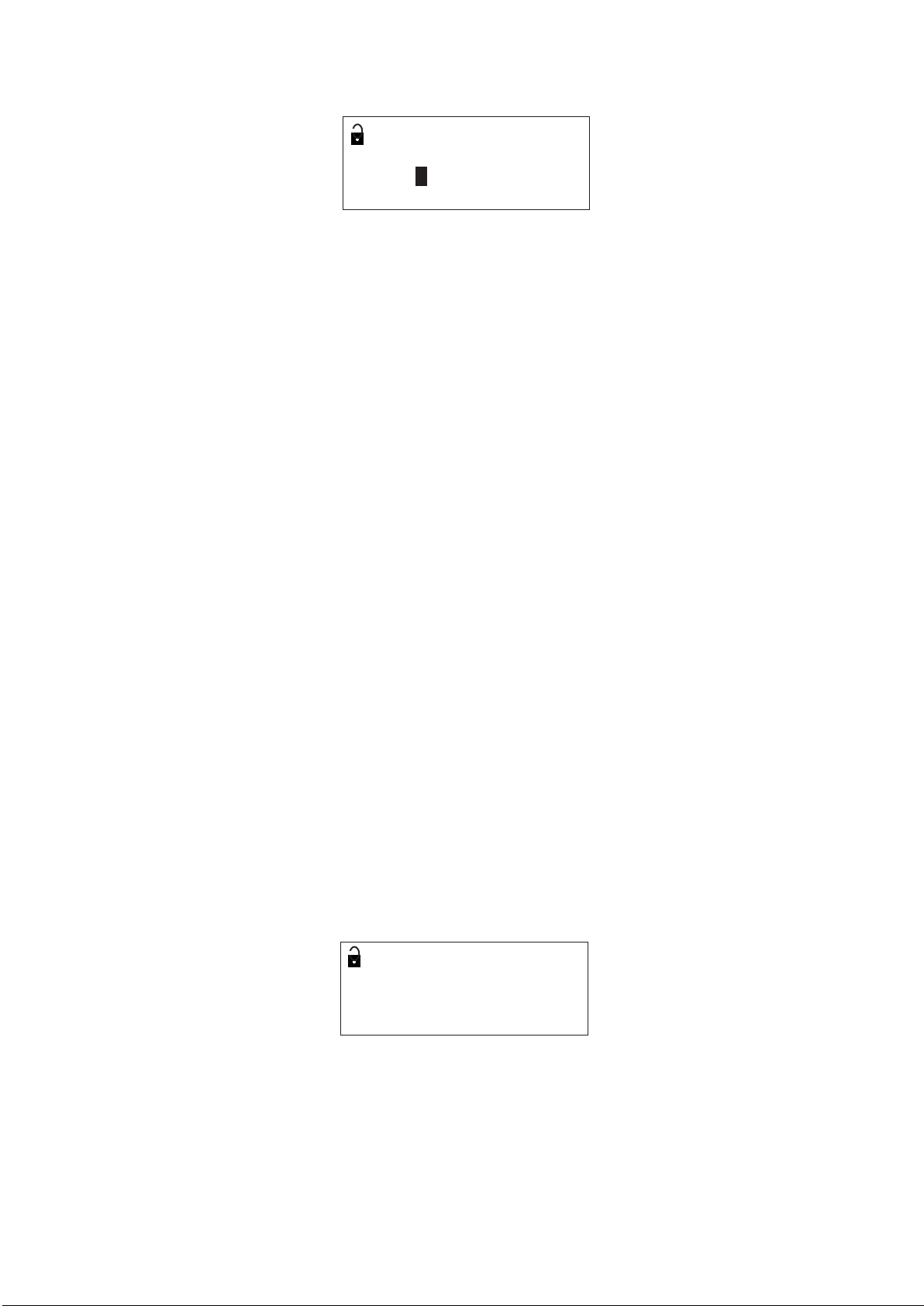
14. Pressing ß will display the next item in the menu, RL1 On Point.
0
RL1 On Point % 0
0.00 P411
15. This is a numeric parameter, therefore pressing Þ highlights the first digit that can be edited.
0
RL1 On Point % 0
000.00 P411
16. Select the digit to be edited by pressing Þ as necessary.
0
RL1 On Point % 0
000.00 P411
IP258
18
17. The value of the digit may now be incremented or decremented by pressing ⇑ ⇓.
0
RL1 On Point% 0
003.00 P411
18. Press ENT to store the value. The highlighting will disappear. If an invalid number is entered then the display
will revert to the last valid value.
19. The relay off point is programmed in the same way (all other numeric parameters are programmed in a similar
way).
20. When programming is complete, return to the TOGGLE RUN menu and close the padlock.
21. Note; any programme changes will not alter the outputs, which remain frozen,
until the TOGGLE RUN padlock has been closed.
5.3 DIAGNOSTIC PARAMETERS
Apart from the user-settable parameters described above, there is another set of diagnostic parameters, which display
measured or calculated data to analyse and optimise system performance. These have the prefix “D” and cannot be
modified.
5.4 EX-FACTORY SYSTEM FEATURES
The MSM400 Control Unit is supplied with default parameters that allow basic initial operation. The values and
descriptions are listed in appendix two of this manual.
6.0 CALIBRATION
There are several methods for calibrating the MSM400, AUTOCAL and MANUAL ENTRY, these together with some
important basic principles are explained below. Calibration always comprises two stages, zero setting and span setting.
Zero setting calibrates the system so that the control unit indicates 0% solids in clear liquid.
Span and lab value setting calibrates the system to monitor suspended solids accurately.
The recommended, simplest and most accurate method for calibrating the MSM400 is by using the AUTOCAL
procedure, which is explained below.
6.1 ZERO SETTING
INITIAL ZERO
The MSM400 has the facility to warn the operator that the sensors require cleaning. The first zero calibration will be
stored in initial zero reference parameter, “Init zero ref”. Future zero calibrations are compared with this value and
any significant change will produce a warning message like the one shown below.
SET ZERO 0
In clear liquor 0
press ENT to set
Sensor dirty
The actual difference required to produce this warning is programmed in dirty point (SETUP – ENGINEERING
– SENSOR LIMITS – Dirty Pt). The default value is 0, which disables this feature. To enable the feature it is
suggested that a value of approximately 6 dB is entered.
Note: this warning feature is not active until the first zero calibration has been carried out.
To reset or clear initial zero value, ‘0’ must entered in Initial zero reference parameter (CALIBRATION – MANUAL
ENTRY – ZERO REF – “Init Zero–1MHz” and “Init Zero–3MHz”, P123 & P124).
 Loading...