


 Loading...
Battery Monitor Data Manager
User’s Guide
3103 No. Andrews Ave. Ext.
Pompano Beach, FL 33064
Tel: (954) 623-6660 Fax: (954) 623-6671
www.alber.com
4200-004 Rev 6.12
1. WARRANTY AND LIMITATION OF LIABILITY
LIMITED WARRANTY. Albércorp warrants that the software product will perform in accordance with the accompanying written materials for a period of ninety (90) days from the date of receipt. Some states and jurisdictions do not allow limitations on duration of an implied warranty, so the above limitation may not apply to you. To the extent allowed by applicable law, implied warranties on the software product, if any, are limited to ninety (90) days.
CUSTOMER REMEDIES. Albércorp's entire liability and your exclusive remedy shall be, at Albércorp's option, either return of the price paid, or replacement of the software product that is returned to Albércorp with proof of purchase. This Limited Warranty is void if failure of the software product has resulted from accident, abuse or misapplication. Any replacement software product will be warranted for the remainder of the original period or thirty (30) days, whichever is longer.
Albércorp shall not be liable for any data or programs stored in or used in conjunction with this software product. Without prejudice to the foregoing generality, Albércorp shall not be liable for the loss or corruption of data or programs stored in or used in conjunction with this or any other software product, nor shall Albércorp be liable for the cost of retrieving or replacing lost or corrupted data.
Albércorp's sole and exclusive liability, for any and all losses and damages arising out of any cause whatsoever, shall in no event exceed the purchase price of the software product purchased.
NO LIABILITY FOR CONSEQUENTIAL DAMAGES. Albércorp shall not in any case be liable for any damages, including special, incidental, indirect, exemplary, collateral or consequential, arising from breach of warranty, breach of contract, negligence or under any other legal theory arising from the warranty herein stated or the purchase of product, including, without limitation, loss of profits, use or goodwill.
Some states and countries do not allow the exclusion or limitation of incidental or consequential damages; therefore, the above exclusion or limitation may not apply to you. This warranty gives you specific legal rights, and you may also have other rights which vary state to state and country to country.
2. SOFTWARE LICENSE AGREEMENT
THIS IS A LEGAL AGREEMENT. PLEASE READ BEFORE INSTALLING SOFTWARE.
Any use of this media other than to review this Software License Agreement constitutes your acceptance of and agreement with the terms of this Software License Agreement with respect to the Albércorp Software. If you do not accept and agree to these terms, you must return the full product with proof of purchase to Albércorp within thirty (30) days for a full refund. Installation or use of this software product constitutes your acceptance of and agreement with the terms of this Software License Agreement.
LICENSORS. All software on this media is licensed to you by Albércorp.
GRANT OF LICENSE. You are granted the right to use the Albércorp Software on a single personal computer. You may copy the software to use with this personal computer to any one hard disk drive of this personal computer and to the memory of this personal computer, provided that you reproduce all copyright and trademark notices, restricted rights legends, and other proprietary markings.
RESTRICTIONS. You may not sublicense, rent or lease the Albércorp Software. You may not reverse engineer, decompile, disassemble, modify, translate or create derivative works of the Software.
LIMITED WARRANTIES AND LIMITATION OF LIABILITY. The limited warranties and limitation of liability in Section 1 of this file apply to, are incorporated in, and are made a part of this Software License Agreement.
i
EXPORT LAW ASSURANCES. You acknowledge and agree that the Software is subject to restrictions and controls imposed by the United States Export Administration Act (the "Act") and the regulations thereunder. You agree and certify that neither the Software nor any direct product thereof is being or will be acquired, shipped, transferred or exported, directly or indirectly, into any country, or used for any purpose, except as authorized by the Act and the regulations.
GOVERNMENT LICENSEE. If you are acquiring the software on behalf of any unit or agency of the United States Government, the provisions of Section 3 apply to, are incorporated in, and are made a part of this Software License Agreement.
GENERAL. This Software License Agreement will be governed by the laws of the State of Florida, except for that body of law dealing with conflicts of law. Should you have any questions concerning this Software License Agreement, or if you desire to contact Albércorp for any reason, please contact:
Albércorp, 3103 No. Andrews Ave. Ext., Pompano Beach, FL 33064
3. GOVERNMENT PROVISIONS
The Government acknowledges the representations of the Albércorp software as "Restricted Computer Software" as the term is defined in Clause 52.227-19 of the Federal Acquisition Regulations (FAR) and is "Commercial Computer Software" as that term is defined in Clause 52.227-7013(a)(1) of the Department of Defense Federal Acquisition Regulation Supplement (DFARS). The Government agrees that:
(i)if the software is supplied to the Department of Defense (DOD), the software is classified as "Commercial Computer Software" and the Government is acquiring only "restricted rights" in the software and its documentation as that term is defined in Clause 252.227-7013(c)(1) of the DFARS, and
(ii)if the software is supplied to any unit or agency of the United States Government other than DOD, the Government's rights in the software and its documentation will be as defined in Clause 51.227-19(c)(2) of the FAR.
RESTRICTED RIGHTS LEGEND. Use, duplication, or disclosure by the Government is subject to restrictions as set forth in subparagraph (c)(1)(ii) of the Rights in Technical Data and Computer Software clause at DFARS 252.227-7013.
ii
4. REGULATORY INFORMATION
Type of Service: The MPM Series and the BDS Series equipment is designed to be used on standard device telephone lines. It connects to the telephone line by means of a standard jack called the USOC RJ11C (or USOC FJ45S). Connection to telephone company provided coin service (central office implemented systems) is prohibited. Connection to party line service is subject to state tariffs.
Telephone Company Procedures: The goal of the telephone company is to provide you with the best service it can. To do this, it may occasionally be necessary for the company to make changes in its equipment, operations or procedures. If these changes might affect your service or the operation of your equipment, the telephone company will give you notice, in writing, to allow you to make any changes necessary to maintain uninterrupted service.
In certain circumstances, it may be necessary for the telephone company to request information from you concerning the equipment that you have connected to your telephone line. Upon request of the telephone company, provide the FCC registration number and the ringer equivalence number (REN); both of these items are listed on the equipment label. The sum of all the RENs on your telephone line should be less than five in order to assure proper service from the telephone company. In some cases, a sum of five may not be useable on a given line.
If Problems Arise: If any of your telephone equipment is not operating properly, you should immediately remove it from your telephone line, as it may cause harm to the telephone network. If the telephone company notes a problem, it may temporarily discontinue service. When practical, the company will notify you in advance of the disconnection. If advance notice is not feasible, you will be notified as soon as possible. When you are notified, you will be given the opportunity to correct the problem and informed of your right to file a complaint with the FCC. Contact your telephone company if you have any questions about your telephone line.
Albércorp
3103 No. Andrews Ave. Ext. Pompano Beach, FL 33064 (954) 623-6660
Information in this document is subject to change without notice.
This manual is for use with the following versions of software and firmware:
BMDM Software Version 5.59 or later
MPM Firmware Version 2.11 or later
BDS Controller Firmware Version 2.41 or later
DCM Firmware Version 3.01 or later
Battery Monitor Data Manager User’s Guide,
Part Number 4200-004, Book Revision 6.12
1999, 2014 Albércorp, 3103 No. Andrews Ave. Ext., Pompano Beach, FL 33064
This manual may not be copied in whole or in part without express written permission from Albércorp.
Microsoft, Microsoft Windows, Microsoft Explorer, and Microsoft Access are registered trademarks of Microsoft Corporation. Pentium is a registered trademark of Intel Corp. WinZip is a registered trademark of Nico Mak Computing, Inc. UL is a registered trademark of Underwriters Laboratories, Inc. Adobe Acrobat is a registered trademark of Adobe Systems, Inc.
Printed in the United States of America
iii
iv
Table of Contents
1. |
SAFETY INFORMATION ......................................................................................................................... |
1-1 |
|
|
1.1. If You Have Questions ................................................................................................................ |
1-1 |
|
2. |
SYSTEM REQUIREMENTS ...................................................................................................................... |
2-1 |
|
3. STRING STATUS SCREEN BUTTONS ...................................................................................................... |
3-1 |
||
4. PROGRAM INSTALLATION AND OPTIONS .............................................................................................. |
4-1 |
||
|
4.1. |
Sample Databases........................................................................................................................ |
4-1 |
|
4.2. |
Installing the BMDM................................................................................................................... |
4-1 |
|
4.3. |
Starting the Program.................................................................................................................... |
4-1 |
|
4.4. Configuring BMDM to Run as a Windows Service .................................................................... |
4-2 |
|
|
4.5. |
Database Notes ............................................................................................................................ |
4-4 |
|
4.6. |
Default Passwords ....................................................................................................................... |
4-4 |
|
4.7. |
Computer Types .......................................................................................................................... |
4-5 |
|
4.8. |
Changing Computer Type............................................................................................................ |
4-6 |
|
4.9. |
File Types .................................................................................................................................... |
4-7 |
|
4.10. |
Help Screens............................................................................................................................ |
4-7 |
5. |
USING CONFIGURE STATION ................................................................................................................ |
5-1 |
|
|
5.1. |
BMDM Configuration Wizard .................................................................................................... |
5-5 |
6. |
UNDERSTANDING COMPUTER TYPES ................................................................................................... |
6-1 |
|
|
6.1. |
Central Computer ........................................................................................................................ |
6-1 |
|
6.2. |
Local Computer ........................................................................................................................... |
6-2 |
|
6.3. |
Service Computer ........................................................................................................................ |
6-3 |
|
6.4. |
Facility Monitor........................................................................................................................... |
6-3 |
7. UNDERSTANDING POLLING, EXTRACTION AND BACKUP...................................................................... |
7-1 |
||
|
7.1. |
Types of Polling .......................................................................................................................... |
7-1 |
|
7.2. |
Extraction of Data........................................................................................................................ |
7-1 |
|
7.3. Polling and Extraction Notes ....................................................................................................... |
7-2 |
|
|
7.4. Automatic and Manual Backup ................................................................................................... |
7-2 |
|
8. |
UNDERSTANDING SYSTEM INSTALLATION ........................................................................................... |
8-1 |
|
|
8.1. Connecting Using a Local Computer........................................................................................... |
8-1 |
|
|
8.2. Connecting Using a Central Computer........................................................................................ |
8-2 |
|
|
8.3. Connecting Using a Service Computer........................................................................................ |
8-3 |
|
9. UNDERSTANDING HOW DATA IS STORED............................................................................................. |
9-1 |
||
|
9.1. Data Storage in the MPM ............................................................................................................ |
9-1 |
|
|
9.2. Data Storage in the BDS.............................................................................................................. |
9-2 |
|
10. |
UNDERSTANDING THE TIME TO GO ALGORITHM............................................................................ |
10-1 |
|
11. |
SELECTING PREFERENCES .............................................................................................................. |
11-1 |
|
12. |
SETTING COMMUNICATIONS .......................................................................................................... |
12-1 |
|
|
12.1. |
Determining the USB COM Port........................................................................................... |
12-2 |
13. |
SETTING UP AN EMAIL ACCOUNT .................................................................................................. |
13-1 |
|
|
13.1. |
Testing Email......................................................................................................................... |
13-2 |
14. |
SETTING UP A NEW MPM OR BDS SYSTEM................................................................................... |
14-1 |
|
|
14.1. |
System Setup: General Notes ................................................................................................ |
14-1 |
|
14.2. |
System Setup: Customer........................................................................................................ |
14-2 |
|
14.3. |
System Setup: Location ......................................................................................................... |
14-3 |
|
14.4. |
System Setup: Battery ........................................................................................................... |
14-4 |
|
14.5. |
System Setup: String ............................................................................................................. |
14-6 |
|
14.6. |
System Setup: Link................................................................................................................ |
14-7 |
|
14.7. |
System Setup: Reporting ....................................................................................................... |
14-9 |
|
14.7.1. Using a Cell Phone for Text Messaging .......................................................................... |
14-11 |
|
|
14.8. |
System Setup: Contact List.................................................................................................. |
14-11 |
|
14.9. |
System Setup: Password...................................................................................................... |
14-14 |
15. |
SYNCHRONIZING USING CHECK SETTINGS ..................................................................................... |
15-1 |
|
v
15.1. |
|
Connecting With a Service Computer ................................................................................... |
15-3 |
|
16. |
CHECK SETTINGS SCREENS ............................................................................................................ |
16-1 |
||
16.1. |
|
Check Settings Screens in Controller .................................................................................. |
16-11 |
|
17. |
PROGRAMMING BATTERY SETUP FOR THE MPM ........................................................................... |
17-1 |
||
17.1. |
|
Battery Setup: General (MPM).............................................................................................. |
17-2 |
|
17.2. |
|
Battery Setup: Parameters (MPM)......................................................................................... |
17-4 |
|
17.3. |
|
Battery Setup: Test Parameters (MPM)................................................................................. |
17-5 |
|
17.4. |
|
Battery Setup: Float Alarms (MPM) ..................................................................................... |
17-6 |
|
17.5. |
|
Battery Setup: Discharge (MPM) .......................................................................................... |
17-9 |
|
17.6. |
|
Battery Setup: Digital Input (MPM).................................................................................... |
17-11 |
|
17.7. |
|
Battery Setup: Digital Output (MPM) ................................................................................. |
17-12 |
|
Battery Setup: LGS (MPM)................................................................................................................. |
17-13 |
|||
18. |
PROGRAMMING BATTERY SETUP FOR THE BDS............................................................................. |
18-1 |
||
18.1. |
|
Battery Setup: General (BDS) ............................................................................................... |
18-2 |
|
18.2. |
|
Battery Setup: Parameters (BDS) .......................................................................................... |
18-4 |
|
18.3. |
|
Battery Setup: Test Parameters (BDS) .................................................................................. |
18-9 |
|
18.4. |
|
Battery Setup: Float Alarms (BDS)..................................................................................... |
18-10 |
|
18.5. |
|
Battery Setup: System (BDS) .............................................................................................. |
18-14 |
|
18.6. |
|
Battery Setup: Discharge (BDS).......................................................................................... |
18-16 |
|
18.7. |
|
Battery Setup: Digital Input (BDS) ..................................................................................... |
18-18 |
|
18.8. |
|
Battery Setup: Digital Output (BDS)................................................................................... |
18-19 |
|
18.9. |
|
Battery Setup: LGS (BDS) .................................................................................................. |
18-20 |
|
19. |
SELECTING THE DATABASE RANGE................................................................................................ |
19-1 |
||
20. |
CONNECTING TO A BATTERY LOCATION ........................................................................................ |
20-1 |
||
20.1. |
|
Connecting via Modem ......................................................................................................... |
20-1 |
|
20.2. |
|
Modem Hang Up ................................................................................................................... |
20-1 |
|
20.3. |
|
Connecting via Network........................................................................................................ |
20-1 |
|
20.4. |
|
Connecting via RS-232 Local Port........................................................................................ |
20-1 |
|
21. |
VIEWING BATTERY AND MONITOR STATUS ................................................................................... |
21-1 |
||
21.1. |
|
Opening and Saving a Database ............................................................................................ |
21-1 |
|
21.2. |
|
String Status Screen............................................................................................................... |
21-2 |
|
21.3. |
|
Report Alarm Event Screens ................................................................................................. |
21-4 |
|
21.4. |
|
Summary Screen.................................................................................................................... |
21-5 |
|
21.5. |
|
Historical Events Screen........................................................................................................ |
21-5 |
|
21.6. |
|
String View Screens .............................................................................................................. |
21-6 |
|
21.7. |
|
Cell Voltage (String View Screen) ........................................................................................ |
21-7 |
|
21.8. |
|
Cell Resistance and Intercell Resistance (String View Screens) ........................................... |
21-8 |
|
21.9. |
|
Historical Graphs................................................................................................................. |
21-10 |
|
21.10. |
Cell Voltage Box ................................................................................................................. |
21-11 |
||
21.11. |
Trend Analysis..................................................................................................................... |
21-11 |
||
21.12. |
Alarm Data .......................................................................................................................... |
21-12 |
||
21.13. |
Alarm Acknowledge............................................................................................................ |
21-15 |
||
21.14. |
Discharge Data .................................................................................................................... |
21-15 |
||
21.14.1. |
Discharge Replay......................................................................................................... |
21-18 |
||
21.14.2. |
Discharge Curve .......................................................................................................... |
21-19 |
||
21.14.3. |
Summary...................................................................................................................... |
21-21 |
||
21.15. Cell Memo / String Memo................................................................................................... |
21-22 |
|||
22. |
USING THE REPORT GENERATOR.................................................................................................... |
22-1 |
||
22.1. |
|
Detail Cell Voltage Report .................................................................................................... |
22-1 |
|
22.2. |
|
Detail Cell Resistance Report................................................................................................ |
22-3 |
|
22.3. |
|
Detail Intercell Resistance Report ......................................................................................... |
22-4 |
|
22.4. |
|
Trend Cell Voltage Report..................................................................................................... |
22-5 |
|
22.5. |
|
Trend Cell Resistance Report ................................................................................................ |
22-6 |
|
22.6. |
|
Trend Intercell Report ........................................................................................................... |
22-7 |
|
22.7. |
|
Trend Overall Voltage Report ............................................................................................... |
22-8 |
|
22.8. |
|
Trend Temperature Report .................................................................................................... |
22-9 |
|
vi
22.9. |
|
Trend Intertier Report............................................................................................................ |
22-9 |
|
22.10. |
Discharge Report ................................................................................................................. |
22-10 |
||
22.11. |
Alarm Report ....................................................................................................................... |
22-11 |
||
22.12. |
Summary Report.................................................................................................................. |
22-12 |
||
23. |
USING THE PREVIEW SCREENS ....................................................................................................... |
23-1 |
||
23.1. |
|
Saving a Report in Archive (ZRF) Format ............................................................................ |
23-2 |
|
23.2. |
|
Printing a Report.................................................................................................................... |
23-2 |
|
23.3. |
|
Opening an Archive File........................................................................................................ |
23-2 |
|
23.4. |
|
Archive Reader Program ....................................................................................................... |
23-2 |
|
24. |
USING THE WEB REPORT GENERATOR ........................................................................................... |
24-1 |
||
24.1. |
|
Setting Up the Web Report.................................................................................................... |
24-1 |
|
24.2. |
|
Generating an Executive Summary Report............................................................................ |
24-3 |
|
25. |
CALIBRATION................................................................................................................................. |
25-1 |
||
26. |
MPM DIAGNOSTICS ....................................................................................................................... |
26-1 |
||
26.1. |
|
Rebooting and Power Up Diagnostics (MPM) ...................................................................... |
26-1 |
|
26.2. |
|
Self Test (MPM).................................................................................................................... |
26-2 |
|
26.3. |
|
Load Module (MPM)............................................................................................................. |
26-3 |
|
26.4. |
|
DIP Switch (MPM)................................................................................................................ |
26-4 |
|
26.5. |
|
Indicator (MPM).................................................................................................................... |
26-5 |
|
26.6. |
|
Digital Port (MPM) ............................................................................................................... |
26-5 |
|
26.7. |
|
Memory (MPM) .................................................................................................................... |
26-6 |
|
26.8. |
|
Contacts (MPM) .................................................................................................................... |
26-7 |
|
26.9. |
|
Intertier (MPM) ..................................................................................................................... |
26-8 |
|
27. |
BDS DIAGNOSTICS......................................................................................................................... |
27-1 |
||
27.1. |
|
Rebooting and Power Up Diagnostics (BDS)........................................................................ |
27-1 |
|
27.2. |
|
Self Test (BDS) ..................................................................................................................... |
27-1 |
|
27.3. |
|
Load Module (BDS) .............................................................................................................. |
27-3 |
|
27.4. |
|
DIP Switch (BDS) ................................................................................................................. |
27-5 |
|
27.5. |
|
Indicator (BDS) ..................................................................................................................... |
27-6 |
|
27.6. |
|
Digital Port (BDS)................................................................................................................. |
27-6 |
|
27.7. |
|
Memory (BDS)...................................................................................................................... |
27-7 |
|
27.8. |
|
Contacts (BDS)...................................................................................................................... |
27-8 |
|
27.9. |
|
Intertier (BDS)....................................................................................................................... |
27-8 |
|
27.10. |
Communication Error (BDS)................................................................................................. |
27-9 |
||
27.11. |
Resistance Testing Multiple DCM Units............................................................................. |
27-10 |
||
28. |
UPGRADES...................................................................................................................................... |
28-1 |
||
29. |
COMMISSIONING ASSISTANT .......................................................................................................... |
29-1 |
||
29.1. |
|
Starting the Assistant for a New String ................................................................................. |
29-1 |
|
29.2. |
|
Monitor Pre-Power Check List.............................................................................................. |
29-2 |
|
29.3. |
|
Starting the Assistant for an Existing String.......................................................................... |
29-3 |
|
29.4. |
|
Completing the Commissioning Assistant............................................................................. |
29-4 |
|
29.4.1. |
|
Commissioning Agent Screen ........................................................................................... |
29-4 |
|
29.4.2. |
|
Equipment Owner Screen .................................................................................................. |
29-5 |
|
29.4.3. Post Power Check Screen .................................................................................................. |
29-6 |
|||
29.4.4. Send Battery Setup Screen................................................................................................. |
29-7 |
|||
29.4.5. |
|
Check Settings Screen ....................................................................................................... |
29-7 |
|
29.4.6. |
|
Serial Numbers Screen ...................................................................................................... |
29-8 |
|
29.4.7. Check Cell Voltage Screen................................................................................................ |
29-8 |
|||
29.4.8. Check Overall Voltage Screen........................................................................................... |
29-9 |
|||
29.4.9. |
|
Check Intertier Screen ....................................................................................................... |
29-9 |
|
29.4.10. |
Base Data - Cell Voltage Screen.................................................................................. |
29-10 |
||
29.4.11. |
Check Float Current Screen......................................................................................... |
29-10 |
||
29.4.12. |
Check Temperature Screen.......................................................................................... |
29-11 |
||
29.4.13. |
Check Discharge Current Screen................................................................................. |
29-11 |
||
29.4.14. |
Check Test Current Screen .......................................................................................... |
29-12 |
||
29.4.15. |
Check Intercell Screen (BDS Only)............................................................................. |
29-13 |
||
vii
29.4.16. |
Base Data - Cell Resistance Screen ............................................................................. |
29-13 |
|
29.4.17. |
Report Screen .............................................................................................................. |
29-14 |
|
29.4.18. |
Preventive Maintenance Report Form ......................................................................... |
29-15 |
|
29.5. |
Emailing a Report................................................................................................................ |
29-16 |
|
29.6. |
Retrieving a Commissioning Report.................................................................................... |
29-16 |
|
29.7. |
Printing a Commissioning Report ....................................................................................... |
29-16 |
|
30. |
ERROR CODES ................................................................................................................................ |
30-1 |
|
viii

Table of Figures
IMPORTANT NOTE: The drawings or figures in this manual may not be the most recent revision and are included for reference only. Refer to the Engineering Drawing Package included with your system for the newest drawings.
Drawings or figures in this manual may be for reference only or superseded by later drawings. For the latest information, refer to the drawings supplied with your system.
Figure 1. BMDM Opening Screen .............................................................................................................. |
4-1 |
Figure 2. AlwaysUp Program Compatibility Assistant ................................................................................. |
4-2 |
Figure 3. BMDM and AlwaysUp Running as a Service.............................................................................. |
4-3 |
Figure 4. BMDM is Running as a Service................................................................................................... |
4-3 |
Figure 5. Select Computer Type.................................................................................................................. |
4-5 |
Figure 6. Config3.MPM File ....................................................................................................................... |
4-6 |
Figure 7. Configure Station - Monitor Connection Type ............................................................................ |
5-1 |
Figure 8. Configure Station - Select Serial Port .......................................................................................... |
5-1 |
Figure 9. Configure Station - Select Number of Modems ........................................................................... |
5-2 |
Figure 10. Configure Station - Set Modem Port.......................................................................................... |
5-2 |
Figure 11. Configure Station - Set Dial Prefix ............................................................................................ |
5-2 |
Figure 12. Configure Station - Set Station Phone Number.......................................................................... |
5-3 |
Figure 13. Configure Station - Remote Reporting....................................................................................... |
5-3 |
Figure 14. Configure Station - Remote Reporting Types............................................................................ |
5-3 |
Figure 15. Configure Station - Email Setup ................................................................................................ |
5-4 |
Figure 16. Configure Station - Select Printer .............................................................................................. |
5-4 |
Figure 17. Configure Station - Set Temperature.......................................................................................... |
5-4 |
Figure 18. Configure Station - Information................................................................................................. |
5-5 |
Figure 19. BMDM Configuration Wizard Opening Screen......................................................................... |
5-5 |
Figure 20. Computer Types: Backup, Polling and Extraction Table........................................................... |
7-3 |
Figure 21. Preferences............................................................................................................................... |
11-1 |
Figure 22. Communication Setup.............................................................................................................. |
12-1 |
Figure 23. Email Setup .............................................................................................................................. |
13-1 |
Figure 24. Test Email ................................................................................................................................ |
13-2 |
Figure 25. System Setup - Customer ......................................................................................................... |
14-2 |
Figure 26. System Setup - Location .......................................................................................................... |
14-3 |
Figure 27. System Setup - Battery............................................................................................................. |
14-4 |
Figure 28. System Setup - String (MPM shown)....................................................................................... |
14-6 |
Figure 29. System Setup - Link................................................................................................................. |
14-7 |
Figure 30. System Setup - Reporting......................................................................................................... |
14-9 |
Figure 31. System Setup - Contact List ................................................................................................... |
14-11 |
Figure 32. System Setup - Contact Information ...................................................................................... |
14-12 |
Figure 33. System Setup - Password ....................................................................................................... |
14-14 |
Figure 34. Connection Error Message ....................................................................................................... |
15-2 |
Figure 35. Check Settings - General (MPM / BDS) .................................................................................. |
16-1 |
Figure 36. Check Settings - Parameters (MPM)........................................................................................ |
16-2 |
Figure 37. Check Settings - Parameters (BDS) ......................................................................................... |
16-2 |
Figure 38. Check Settings - Test Parameters (MPM / BDS) ..................................................................... |
16-3 |
Figure 39. Check Settings - Float Alarms (MPM)..................................................................................... |
16-4 |
Figure 40. Check Settings - Float Alarms (BDS) ...................................................................................... |
16-4 |
Figure 57. Check Settings - Float Alarms (BDS) ...................................................................................... |
16-5 |
Figure 41. Check Settings - Discharge (MPM / BDS) .............................................................................. |
16-6 |
Figure 42. Check Settings - Digital Input (MPM)..................................................................................... |
16-7 |
Figure 43. Check Settings - Digital Input (BDS)....................................................................................... |
16-7 |
ix
Figure 44. Check Settings - Digital Output (MPM) .................................................................................. |
16-8 |
Figure 45. Check Settings - Digital Output (BDS/256)............................................................................. |
16-8 |
Figure 46. Check Settings - Calibration (MPM)........................................................................................ |
16-9 |
Figure 47. Check Settings - Calibration (BDS) ......................................................................................... |
16-9 |
Figure 48. Check Settings - LGS (MPM / BDS) ..................................................................................... |
16-10 |
Figure 49. Check Settings in Controller - Typical Screen (BDS)............................................................ |
16-11 |
Figure 50. Battery Setup - General (MPM) ............................................................................................... |
17-2 |
Figure 51. Battery Setup - Parameters (MPM).......................................................................................... |
17-4 |
Figure 52. Battery Setup - Test Parameters (MPM) .................................................................................. |
17-5 |
Figure 53. Battery Setup - Float Alarms (MPM)....................................................................................... |
17-6 |
Figure 54. Cell Resistance Alarm Levels Setup (MPM) ........................................................................... |
17-7 |
Figure 55. Battery Setup - Discharge (MPM) ........................................................................................... |
17-9 |
Figure 56. Battery Setup - Digital Input (MPM) ..................................................................................... |
17-11 |
Figure 57. Battery Setup - Digital Output (MPM)................................................................................... |
17-12 |
Figure 58. Battery Setup - LGS (MPM) .................................................................................................. |
17-13 |
Figure 59. Battery Setup - General (BDS)................................................................................................. |
18-2 |
Figure 60. Battery Setup - Parameters (BDS-256) .................................................................................... |
18-4 |
Figure 61. BDS Configuration Data for Setup Files.................................................................................. |
18-6 |
Figure 62. BDS Configuration Data for Setup Files (continued) .............................................................. |
18-7 |
Figure 63. Battery Setup - Test Parameters (BDS).................................................................................... |
18-9 |
Figure 64. Battery Setup - Float Alarms (BDS) ...................................................................................... |
18-10 |
Figure 65. Cell Resistance Alarm Levels Setup (BDS)........................................................................... |
18-11 |
Figure 66. Input Alarm Level (Intertier Resistance Alarm Level) .......................................................... |
18-12 |
Figure 67. Battery Setup - Thermal Runaway (BDS).............................................................................. |
18-14 |
Figure 69. Battery Setup - Discharge (BDS) ........................................................................................... |
18-16 |
Figure 70. Battery Setup - Digital Input (BDS-256) ............................................................................... |
18-18 |
Figure 71. Battery Setup - Digital Output (BDS-256)............................................................................. |
18-19 |
Figure 72. Battery Setup - LGS (BDS).................................................................................................... |
18-20 |
Figure 73. Select Database Range ............................................................................................................. |
19-1 |
Figure 74. String Status ............................................................................................................................. |
21-2 |
Figure 75. String Status Viewing Selection............................................................................................... |
21-3 |
Figure 76. Strings in Alarm ....................................................................................................................... |
21-3 |
Figure 77. Report Alarm Event ................................................................................................................. |
21-4 |
Figure 78. Summary (Battery Sites) .......................................................................................................... |
21-5 |
Figure 79. Historical Events ...................................................................................................................... |
21-5 |
Figure 80. String View - Cell Voltages (MPM shown)............................................................................. |
21-7 |
Figure 81. String View - Cell Resistance (MPM shown) .......................................................................... |
21-8 |
Figure 82. String View - Intercell Resistances (BDS only)....................................................................... |
21-9 |
Figure 83. History Options and Record Date/Time Box ......................................................................... |
21-10 |
Figure 84. Cell Voltage Box.................................................................................................................... |
21-11 |
Figure 85. Trend Menu............................................................................................................................ |
21-12 |
Figure 86. Trend - Cell Voltage (Typical of all Trend screens) .............................................................. |
21-12 |
Figure 87. Current Alarm List ................................................................................................................. |
21-13 |
Figure 88. Historical Alarm List.............................................................................................................. |
21-14 |
Figure 89. Historical Alarm Selection..................................................................................................... |
21-14 |
Figure 90. All Discharges (MPM shown)................................................................................................ |
21-15 |
Figure 91. Discharge Replay ................................................................................................................... |
21-18 |
Figure 92. Discharge Curve..................................................................................................................... |
21-19 |
Figure 93. Curve Option.......................................................................................................................... |
21-20 |
Figure 94. Summary (Discharges)........................................................................................................... |
21-21 |
Figure 95. Cell Memo and String Memo................................................................................................. |
21-22 |
Figure 96. Detail Cell Voltage Setup......................................................................................................... |
22-1 |
Figure 97. Detail Cell Resistance Setup .................................................................................................... |
22-3 |
Figure 98. Detail Intercell Resistance Setup.............................................................................................. |
22-4 |
Figure 99. Trend Cell Voltage Setup......................................................................................................... |
22-5 |
Figure 100. Trend Cell Resistance Setup .................................................................................................. |
22-6 |
x
Figure 101. Trend Intercell Resistance Setup............................................................................................ |
22-7 |
Figure 102. Trend Overall Voltage Setup.................................................................................................. |
22-8 |
Figure 103. Trend Temperature Setup....................................................................................................... |
22-9 |
Figure 104. Trend Intertier Setup .............................................................................................................. |
22-9 |
Figure 105. Discharge Setup ................................................................................................................... |
22-10 |
Figure 106. Alarms Setup........................................................................................................................ |
22-11 |
Figure 107. Summary Setup .................................................................................................................... |
22-12 |
Figure 108. Preview (Typical Screen) ....................................................................................................... |
23-1 |
Figure 109. Preview (Discharge Report) ................................................................................................... |
23-1 |
Figure 110. Technician Detail Summary Report Setup............................................................................. |
24-1 |
Figure 111. Technician Report - Discharges Area .................................................................................... |
24-2 |
Figure 112. Auto Generating Technician Detail Summary Report ........................................................... |
24-3 |
Figure 113. Calibration Setup (MPM)....................................................................................................... |
25-1 |
Figure 114. Calibration Setup (BDS) ........................................................................................................ |
25-1 |
Figure 115. Diagnostics - Self Test (MPM) .............................................................................................. |
26-2 |
Figure 116. Diagnostics - Load Module - Test Current (MPM)................................................................ |
26-3 |
Figure 117. Diagnostics - DIP Switch (MPM) .......................................................................................... |
26-4 |
Figure 118. Diagnostics - Indicator (MPM) .............................................................................................. |
26-5 |
Figure 119. Diagnostics - Digital Port (MPM).......................................................................................... |
26-5 |
Figure 120. Diagnostics - Memory (MPM)............................................................................................... |
26-6 |
Figure 121. Diagnostics - Alarm Contacts (MPM).................................................................................... |
26-7 |
Figure 122. Diagnostics - Intertier (MPM)................................................................................................ |
26-8 |
Figure 123. Diagnostics - Self Test (BDS)................................................................................................ |
27-1 |
Figure 124. Diagnostics - Load Module - Test Current (BDS) ................................................................. |
27-3 |
Figure 125. Diagnostics - Load Module - CT Polarity (BDS)................................................................... |
27-4 |
Figure 126. Diagnostics - DIP Switch (BDS)............................................................................................ |
27-5 |
Figure 127. Diagnostics - Indicator (BDS)................................................................................................ |
27-6 |
Figure 128. Diagnostics - Digital Port (BDS) ........................................................................................... |
27-6 |
Figure 129. Diagnostics - Memory (BDS) ................................................................................................ |
27-7 |
Figure 130. Diagnostics - Alarm Contacts (BDS) ..................................................................................... |
27-8 |
Figure 131. Diagnostics - Intertier (BDS) ................................................................................................. |
27-8 |
Figure 132. Diagnostics - Communication Error (BDS) ........................................................................... |
27-9 |
Figure 133. Select DCM.......................................................................................................................... |
27-10 |
Figure 134. Setup Menu Showing Upgrade Options (BDS)...................................................................... |
28-1 |
Figure 135. Commissioning Assistant Welcome....................................................................................... |
29-1 |
Figure 136. Monitor Pre-Power Screen (typical)....................................................................................... |
29-2 |
Figure 137. Monitor Pre-Power Load Cable Help Screen......................................................................... |
29-2 |
Figure 138. Open Commissioning Assistant ............................................................................................. |
29-3 |
Figure 139. Commissioning Agent (Comm Asst) ..................................................................................... |
29-4 |
Figure 140. Equipment Owner (Comm Asst)............................................................................................ |
29-5 |
Figure 141. Post Power Check Screen (BDS-256 only) (Comm Asst) ..................................................... |
29-6 |
Figure 142. Send Battery Setup (Comm Asst) .......................................................................................... |
29-7 |
Figure 143. Check Settings (Comm Asst) ................................................................................................. |
29-7 |
Figure 144. Serial Numbers (Comm Asst) ................................................................................................ |
29-8 |
Figure 145. Check Cell Voltage (Comm Asst).......................................................................................... |
29-8 |
Figure 146. Check Overall Voltage (Comm Asst) .................................................................................... |
29-9 |
Figure 147. Check Intertier (Comm Asst) ................................................................................................. |
29-9 |
Figure 148. Base Data - Cell Voltage (Comm Asst) ............................................................................... |
29-10 |
Figure 149. Check Float Current (Comm Asst)....................................................................................... |
29-10 |
Figure 150. Check Temperature (Comm Asst)........................................................................................ |
29-11 |
Figure 151. Check Discharge Current (Comm Asst)............................................................................... |
29-11 |
Figure 152. Check Test Current (Comm Asst) ........................................................................................ |
29-12 |
Figure 153. Check Intercell (Comm Asst)............................................................................................... |
29-13 |
Figure 154. Base Data - Cell Resistance (Comm Asst) ........................................................................... |
29-13 |
Figure 155. Save Base Line and Send Thresholds Data – Cell/Intertier/Inter-Cell Resistance (Comm Asst)
................................................................................................................................................................. 29-14
xi
Figure 156. |
Report (Comm Asst) ............................................................................................................ |
29-14 |
Figure 157. |
Report (Preventive Maintenance) Form ............................................................................... |
29-15 |
xii
xiii
Safety Information
1. Safety Information
•You must read and understand these safety precautions and those elsewhere in this manual before installing, powering up or using the system.
•Except as explained in this manual, do not attempt to service Albér equipment yourself. Opening the equipment may expose you to dangerous voltages. Refer servicing beyond that described in this manual to authorized personnel.
•Do not allow liquids or moisture to get into the equipment. If liquid gets into the equipment, unplug it immediately and contact an authorized service center or Albér.
•The equipment must have adequate ventilation. Do not block equipment ventilation openings.
•Do not exceed equipment voltage, power ratings or capabilities.
•When grounding is required, make sure the equipment is properly grounded.
•Do not let unauthorized persons operate the equipment.
•Do not energize the cabinet or any component with 115VAC (or 230VAC if applicable) or battery voltage until after the installation is complete.
•Use of this product in a manner not specified could compromise the designed-in safety of this product.
•High voltage or current may be present inside the equipment and on the equipment terminals. Only qualified personnel should perform the operations described in this manual. Calibration must be performed only by technically qualified persons. Observe electrical safety precautions when removing and installing equipment covers, when connecting leads, and when making adjustments.
•Proper installation and testing are essential to the correct functioning of your system. If you have any questions, contact Albér.
•This manual describes the general installation and use of the system. If your system has features or accessories not described in this manual, contact Albér.
•Drawings in this manual may be for reference only or superseded by later drawings. For the latest information, refer to the drawings supplied with your system.
1.1.If You Have Questions
If you have any questions about the installation or testing of your system, contact Albér at (954) 623-6660 or fax (954) 623-6671. Request BMDM, MPM or BDS assistance.
1-1
System Requirements
2. System Requirements
These are the minimum requirements for the BMDM (Battery Monitor Data Manager) program.
Microsoft Windows XP, 2000, Windows 7, or 8. Pentium4 1GHz or higher microprocessor.
128Mb of memory for Windows 2000. 256Mb for Windows XP.
150Mb of hard disk space for program installation. 1Gb of space for data storage. CD drive.
A typical MPM system requires these manuals.
Battery Monitor Data Manager User’s Guide, 4200-004 (this book) MPM-100 Installation Instructions, 4200-034
MPM-100, BDS-256 and BDS-40 Monitors Product Description Guide, 4200-039 MPM-100 Commissioning Procedure with Acceptance Test Report, 4200-036 (optional) UPS (uninterruptible power supply) manufacturer's instruction manual (if a UPS is used)
A typical BDS system requires these manuals.
Battery Monitor Data Manager User’s Guide, 4200-004 (this book)
BDS-256 Battery Diagnostic System with BDS Controller Installation Instructions, 4200-028 or BDS-40 Battery Diagnostic System Installation Instructions, 4200-045
MPM-100, BDS-256 and BDS-40 Monitors Product Description Guide, 4200-039
BDS-256 Commissioning Procedure with Acceptance Test Report, 4200-009 (optional)
or BDS-40 Commissioning Procedure with Acceptance Test Report, 4200-057 (optional)
UPS (uninterruptible power supply) manufacturer's instruction manual (if a UPS is used with the system)
BDS Quick Start Cards, 4200-026 (optional)
2-1
String Status Screen Buttons
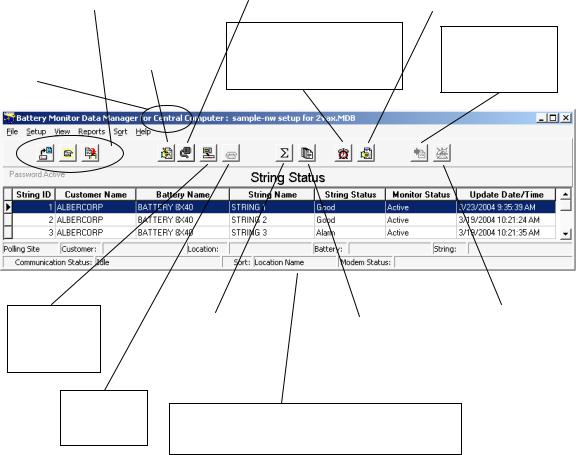
3. String Status Screen Buttons
This page describes buttons on the String Status screen, which appears when the BMDM (Battery Monitor Data Manager) program starts. Each button name or function is listed in the index for ready reference.
|
|
Set Up Communication |
|
|
Open / Close / |
|
|
|
|
|
(Setup|Communication) |
|
|
|
Back Up Database |
|
|
|
|
|
Define ports, modems, |
|
|
|
(File|selection) |
|
|
|
|
|
network timeout. Force |
|
Show All Alarm Events |
|
Open or close a file |
|
|
||
or back up an Access |
|
direct connect. Disable |
|
Display the Report Alarm |
database |
|
auto polling |
|
Event dialog boxes |
|
|
|
|
|
Indicates |
|
Set Up System |
Central, Local |
|
(Alternate is |
or Service |
|
Setup|System) |
computer |
|
|
|
||
|
|
|
Historical Events
(View|Historical Events) List reported events and the history of one or all strings
Extract All Data
Get data from all strings in the system
Connection
Connect to the selected string
Hang Up
Disconnect the modem
|
|
|
|
Call All Modem |
Summary |
|
Summary Report |
||
|
|
Strings |
||
Displays status |
|
|
||
|
Create a report for |
|
Poll all strings |
|
for all strings and |
|
|
||
|
the entire system |
|
attached via modem |
|
monitors |
|
|
||
|
|
|
|
|
|
|
|
|
|
|
|
|
|
|
This portion of the screen displays communication information, polling status, connection names, and error status
String Status screen –String Status appears when the BMDM program starts. It lists the strings in the database and their last known status.
String View screen –String View shows the cells in a string as a bar graph, table or both. It appears after a string is selected on the String Status screen and computer to monitor communication is established. You can view a string off-line by selecting View|Offline.
3-1

Program Installation and Options
4. Program Installation and Options
When installing the BMDM, you will choose Install BMDM Manager. Other screen options provide you with documentation, connection to the Alber Web site or contact information.
Figure 1. BMDM Opening Screen
4.1.Sample Databases
BMDM sample databases provide strings and data you may use to test button actions, observe screens, create graphs, and generate reports.
Sample Database for Access - When using Access, at BMDM start-up a message asks, "Do you want to load a sample database?" Click Yes if you want to explore the BMDM. Clicking Yes opens the AlberDemo.mdb Access database. If the "load a sample database" message does not appear, you may enable it on Setup|Preferences. You may also open the sample file by selecting File|Open|AlberDemo.mdb.
4.2.Installing the BMDM
Before installing the BMDM program, close all other programs. To install the program, insert the CD into the computer and wait for autorun. If the CD does not run, select Start|Run from the Windows desktop. At the Run box, type d:\launch (or other drive letter) and follow the instructions.
4.3.Starting the Program
To start the Battery Monitor Data Manager, double-click the BMDM icon on the desktop. The first time the program runs, "Do you want to load a sample database?" appears. Click No if you want to use the Configure Station screens. Refer to Sample Databases and Using Configure Station.
4-1
Program Installation and Options
4.4.Configuring BMDM to Run as a Windows Service
The BMDM can be run as a service so the application will continue to run in the background even after the user logs off Windows. The following describes how to configure the BMDM software as a service.
Note: the BMDM uses the "AlwaysUp" third party application to run the BMDM as a service. It is automatically installed with the BMDM software package starting with versions 5.86 and SQL 6.33 or later.
To Setup the BMDM as a service using the “AlwaysUp” application, do the following:
1.Check if your operating system is 32 or 64 bit.
2.Click on the appropriate shortcut to install the BMDM Service
a.For 32-bit operating system, click on Start, All Programs, Alber, MPM Manager, then click on the shortcut Install BMDM Service 32-Bit.
b.For 64-bit operating system, click on Start, All Programs, Alber, MPM Manager,
then click on the shortcut Install BMDM Service 64-Bit.
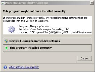
Note: Depending on your operation system, this message may appear. Click on This program installed correctly to finish the installation.
Figure 2. AlwaysUp Program Compatibility Assistant
3.Type Windows key + R and enter Services.msc and check for the BMDMService (managed by AlwaysUpService) entry. Right click the entry and click Start to start the service.
4-2

Program Installation and Options
Figure 3. BMDM and AlwaysUp Running as a Service
4.Type Ctrl+Shift+Esc to open the task manager. Check for the BMDM.exe *32 under the Processes tab. This confirms that the BMDM is running as a service.
Figure 4. BMDM is Running as a Service
5.To launch the BMDM user interface, click Start, All Programs, Alber, MPM Manager, then click on the shortcut Run BMDM Service in Session.
Note: When using the BMDM as a service, use only Run BMDM Service in Session to launch BMDM. Attempting to run the BMDM using the regular icon shortcut will cause issues such as having two instances of BMDM.exe running at the same time or shared violation errors.
4-3
Program Installation and Options
6.It is recommended to replace the regular BMDM shortcut on the desktop with the Run BMDM Service in Session shortcut to prevent the user from launching the BMDM incorrectly.
4.5.Database Notes
A BMDM database file contains cell and battery readings and setup data. The BMDM program stores MPM and BDS data in an Access-based .MDB file.
Access initial database file - During installation, the BMDM places the empty Access database file mpm-db3.mdb under Program Files\Alber\MPM Manager\Database or in another folder selected at time of installation. This empty default database opens when you have not previously opened another database.
Creating a new database - You may create a new Access database using File|New.
Deleting a database - You cannot delete an Access MDB database file from within the BMDM program. To delete a database, use standard Windows procedures to delete the MDB file from the folder where it is saved. The file is typically located at Program Files/Alber/ MPM Manager/Database.
Because databases may contain unrecoverable battery data, regularly back up MDB files to another computer to help prevent data loss. Refer to Automatic and Manual Backup.
4.6.Default Passwords
The BMDM program has one default password, alber, which accesses all areas of the program and can be changed by the user. It is important to note that different passwords may be selected for various program areas. New passwords may be alphanumeric and are not case sensitive.
Additional passwords may be needed when using options. For example, when setting up an email account for alarm notification, the password is determined externally and is not changeable using the BMDM. Be certain to record new passwords for reference. If lost, they cannot be retrieved, and you will have to contact Alber for an unlock code.
System Setup Password - A password for System Setup is stored in the BMDM database and may be eight characters long. To change it, from the String Status screen, select Setup|System|Password. Refer to System Setup: Password.
Battery Setup Password - A password for the Battery Setup, Calibration, Diagnostics, and Check Settings Upload screens is stored in MPM or BDS firmware and must be five characters. To change it, from String Status, select Setup|Battery|General. Refer to Battery Setup: General (MPM or BDS).
The Battery Setup password is cleared from the MPM or BDS firmware when the
Alarm Reset switch clears existing names. Refer to the Clear Existing Names (On-site) text in the Synchronizing Using Check Settings chapter.
4-4
Program Installation and Options
4.7.Computer Types
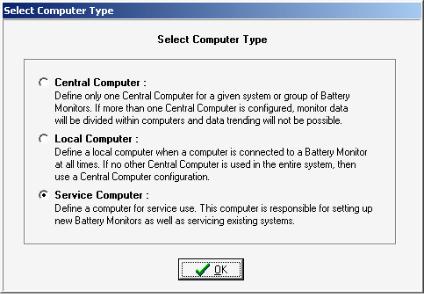
The first time the program runs, a question about computer type appears.
Figure 5. Select Computer Type
You select a computer type only once. Refer to Understanding Computer Types before answering. The following text is on the Select Computer Type box:
Central Computer - Define only one Central computer for a given system or group of battery monitors. If more than one Central computer is configured to extract data, the monitor data could become corrupted.
Local Computer - Define a Local computer when a computer is connected to a battery monitor at all times. If no other Central computer is used in the entire system, then use a Central computer configuration.
Service Computer - Define a computer for Service use. This computer is responsible for setting up new battery monitors as well as servicing existing systems.
On install, the database updates to the latest version. After setup, the String Status screen title bar indicates the computer type: Central, Local or Service. To change the type, refer to
Changing Computer Type.
4-5
Program Installation and Options
4.8.Changing Computer Type
The Select Computer Type box appears only the first time you install the program. You cannot change the computer type by re-installing; you must edit a text file. Close all programs, including the BMDM, and open a text editor, such as Microsoft Notepad or WordPad under Start|Programs|Accessories.
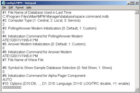
Open the file Config3.MPM under Program Files\Alber\MPM Manager. Using the text editor, edit the number under the line labeled #2 Computer Type so the digit indicates the computer type you want. Type 1 for Central, 2 for Local, or 3 for Service. For example, in the following figure, the 2 under line #2 indicates a Local computer.
Figure 6. Config3.MPM File
Save the text file and close the editor. Run the BMDM program and confirm the title bar indicates the correct computer type: Central, Local or Service. The Config3.MPM file shown above is for illustration and not meant to be copied.
4-6
Program Installation and Options
4.9.File Types
The BMDM program uses several file extensions.
MDB ......... |
An Access database file that stores cell and battery readings and setup data. At |
|
installation, the BMDM creates an empty database file. When the BMDM opens |
|
a backup file, it extracts it from ZIP to MDB. |
MPM ......... |
The configuration file Config3.MPM under Program Files\Alber\MPM Manager |
|
that you may edit to change computer type (Central, Local or Service). |
PDF ........... |
A file format that protects against unintended changes. The Web Report |
|
Generator generates a report as a PDF file every 24 hours. |
WAV......... |
A sound file used for alarm sounds. |
ZIP ............ |
A compressed file for backup of an MDB database file. Saving the working |
|
database as a backup saves the MDB file as a ZIP. |
ZRF ........... |
A compressed file for reports. The Report Generator displays and prints text and |
|
graphs and saves customized reports in a ZRF format that protects against |
|
changes. You may also view and print ZRF files using the Archive Reader. |
4.10. Help Screens
The BMDM has built-in help, which you may activate three ways. Most screens have a question mark in the upper right corner. Click the question mark, then click the ? cursor over an item to open a help description. If a screen has no question mark, press the F1 function key to display help for the entire screen.
Finally, you may click Help on the menu bar to open the text portion of the manual, through which you may browse using the Table of Contents or Index. The on-screen manual does not include tables and figures.
4-7
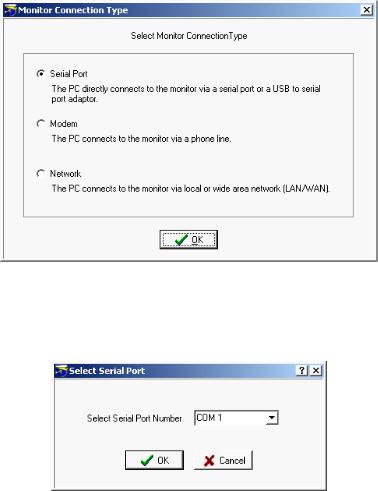
Using Configure Station
5. Using Configure Station
The Configure Station dialog boxes for a Local, Central or Service computer facilitate setting up communication and alarm reporting. The first time the BMDM runs, at the "Do you want to load a sample database?" message, select No to display the boxes. You may later open these boxes by selecting Setup|Configure Station.
String Status > Setup|Configure Station
To start Configure Station, select Setup|Configure Station. The Monitor Connection Type dialog box appears. Because subsequent boxes depend on previous selections, each box is described without reference to others. For more details on dialog box items, refer to the sections mentioned.
Figure 7. Configure Station - Monitor Connection Type
Select the method by which the monitor is connected to the computer.
Figure 8. Configure Station - Select Serial Port
If communicating via serial port, select a COM port.
5-1
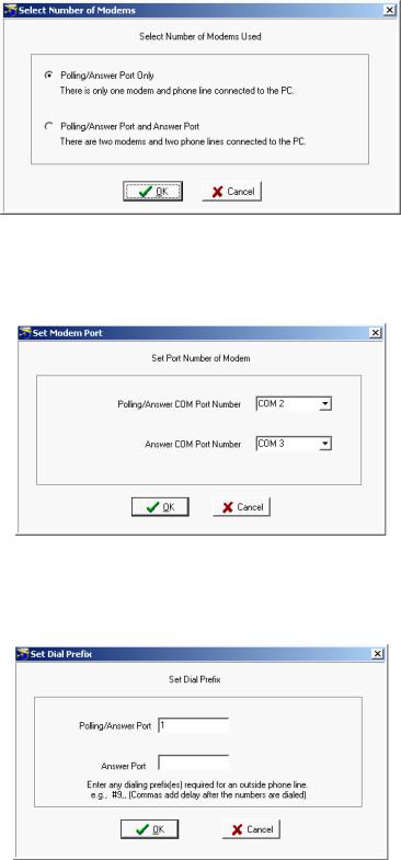
Using Configure Station
Figure 9. Configure Station - Select Number of Modems
If communicating via modem, select the number of modems in use. For details, refer to
Setting Communications.
Figure 10. Configure Station - Set Modem Port
If communicating via modem, select the modem COM ports. For details, refer to Setting Communications.
Figure 11. Configure Station - Set Dial Prefix
If communicating via modem, select the dialing prefix. For more details, refer to Setting Communications.
5-2
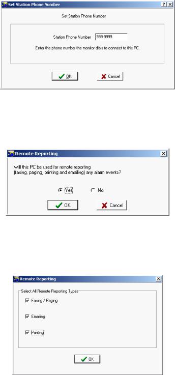
Using Configure Station
Figure 12. Configure Station - Set Station Phone Number
If communicating via modem, type the telephone number of the computer the MPM or BDS monitor calls when a system goes into alarm or discharge.
Figure 13. Configure Station - Remote Reporting
To set up parameters for automatic alarm notification using fax, page, email or print, click Yes.
Figure 14. Configure Station - Remote Reporting Types
Select the methods by which alarms will be reported.
5-3
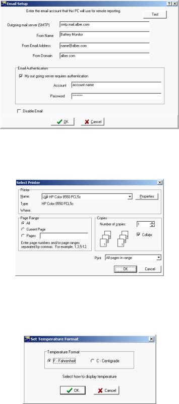
Using Configure Station
Figure 15. Configure Station - Email Setup
If sending alarms via e-mail, complete this dialog box. Refer to Setting Up an Email Account.
Figure 16. Configure Station - Select Printer
If sending alarms to a printer, this dialog box appears, which is also under File|Printer Setup. The key item to select is the default printer.
Figure 17. Configure Station - Set Temperature
This box always appears. Select how temperatures will be displayed, either in degrees Fahrenheit or Centigrade.
5-4
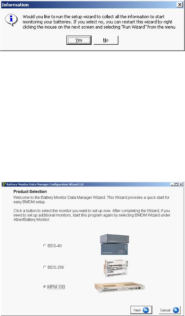
Using Configure Station
Figure 18. Configure Station - Information
If running the BMDM for the first time with an Access database, this box opens the hardware setup wizard. You may start this wizard at any time by selecting Setup|Run Wizard.
5.1.BMDM Configuration Wizard
String Status > Setup|Run Wizard or Right-click mouse|Run Wizard
The BMDM Configuration Wizard sets up monitor hardware and battery strings. Using the Wizard is the recommended method for setup, as it ensures that basic setup requirements are completed. If you choose not to use the Wizard, you must use the various BMDM setup dialog boxes.
To start the Wizard, select Setup|Run Wizard or right click on the String Status screen and select Run Wizard. The self-guided Wizard dialog boxes are not described in this manual.
Figure 19. BMDM Configuration Wizard Opening Screen
5-5
Practical Theory: Understanding Computer Types
Practical Theory
6. Understanding Computer Types
When installing the BMDM program, select one of three computer types: Local, Central or Service. This section explains the types of computers.
6.1.Central Computer
For managing many sites, use a Central computer. This can be a remote computer with one modem, or two modems for more than 100 monitors. A computer continuously running the BMDM can automatically poll the monitoring systems, test for normal status, answer calls from alarming monitors, receive and store data in a central database, report problems to personnel, and list conditions on the String Status screen.
If using only one site with a Central computer, you may connect the computer to a monitor RS-232 rear port for continuous viewing of battery and monitor status. In this configuration, no other Central computers may exist for the same site.
You may temporarily use a portable computer as the Central computer. To manually extract data, connect the computer via modem or RS-232 Local port. This type of Central computer is the least desirable because it cannot automatically poll units for status and automatically extract data or receive calls from alarming monitors.
Only use one Central computer for all monitors. This is important because only a Central computer removes data permanently from monitor memory.
Select Central Computer when you want to:
Connect a computer to manage one or more monitors and have the computer manage the database. Only a Central computer updates the time when passing midnight.
A Central computer can do the following:
Set alarm parameters and test intervals.
Collect data manually or automatically, which permanently removes the data from monitor memory.
Report string and monitor status automatically.
Upon an alarm occurrence, page personnel, fax or email a report, and sound an alarm. Control more than 1000 monitors from a remote location (not on-site).
Assign location, battery, and string names when setting up a new system. Calibrate a monitor when the Central computer is on-site.
Note: You may set up an on-site, remote (off-site) or notebook computer as Central, but there must be only one Central computer polling a monitor. A serial multiplexer is required when using more than one monitor with an on-site computer.
6-1
Loading...