


READ AND SAVE THESE INSTRUCTIONS
“Botanica” Series |
|
|
Model No. |
CF2500OB01 |
CF2500HTW01 |
CF2500S01 |
CF2500TG01 |
Net Weight: 20.0 Lbs. |
|
|
® |
Botanica Series
Ceiling Fan Owner's Manual
Part No. F40BP72200003 |
Form No. BP7220-3 |
|
|

!WARNING
WARNING: To avoid fire, shock, and serious personal injury, follow these instructions.
Safety Instructions
1.Read your owner’s manual carefully and keep it for future reference.
2.Before servicing or cleaning unit, switch power off at service panel and lock service panel disconnecting means to prevent power from being switched on accidentally. When the service disconnecting means cannot be locked, securely fasten a warning device, such as a tag, to the service panel.
3.Be careful of the fan and blades when cleaning, painting, or working near the fan. Always turn off the power to the ceiling fan before servicing.
4.Do not put anything into the fan blades while they are turning.
5.Do not operate reversing switch until fan blades have come to a complete stop.
Additional Safety Instructions for Installation
1.To avoid possible shock, be sure electricity is turned off at the fuse box before wiring, and do not operate fan without blades.
2.All wiring must satisfy National and Local Electrical Codes. Use the National Electrical Code if Local Codes do not exist. The ceiling fan must be grounded as a precaution against possible electrical shock. Electrical installation should be made or approved by a licensed electrician.
3.The outlet box and joist must be securely mounted and capable of reliably supporting at least 50 pounds. Use only U.L. outlet boxes listed as acceptable for fan support, and use the mounting screws provided with the outlet box. Most outlet boxes commonly used for support of light fixtures are not acceptable for fan support and may need to be replaced. Consult a qualified electrician if in doubt.
4.The downrod furnished with the fan provides the minimum recommended floor to fan blade clearance for an 8 foot ceiling.
5.The fan must be mounted with the fan blades at least 7 feet from the floor to prevent accidental contact with the fan blades.
6.Follow the recommended instructions for the proper method of wiring your ceiling fan. If you do not know enough about electrical wiring, have your fan installed by a licensed electrician.
WARNING: To avoid fire, shock or injury, do not use an Emerson or any other brand of control not specifically approved for this fan.
WARNING: This product is designed to use only those parts supplied with this product and/or any accessories designated specifically for use with this product by Emerson. Substitution of parts or accessories not designated for use with this product by Emerson could result in personal injury or property damage.
WARNING: To Reduce the risk of personal injury, do not bend the blade flange when installing the blade flanges, balancing the blades or cleaning the fan. Do not insert foreign objects in between rotating fan blades.
2
This Manual Is Designed to Make it as Easy as Possible for You to Assemble, Install, Operate and Maintain Your Ceiling Fan
Tools Needed for Assembly
One Phillips head screwdriver |
One stepladder |
Three wire connectors (supplied.) |
One wire stripper |
MATERIALS
Wiring, outlet box and box connectors must be of type required by the local code. The minimum wire would be a 3-conductor (2-wire with ground) of size shown at right:
Installed Wire Length |
Wire Size A.W.G. |
Up to 50 ft. |
14 |
50-100 ft. |
12 |
!WARNING
Before assembling your ceiling fan, refer to section on proper method of wiring your fan. If you feel you do not have enough wiring knowledge or experience, have your fan installed by a licensed electrician.
Unpacking Instructions
For your convenience, check-off boxes are provided next to each step. As each step is completed, place a check mark in the box. This will insure that all steps have been completed and will be helpful in finding your place should you be interrupted.
!WARNING
Do not install or use fan if any part is damaged or missing. Call Toll-Free:
1-800-654-3545
!WARNING
This product is designed to use only those parts supplied with this product and/or any accessories designated specifically for use with this product by Emerson. Substitution of parts or accessories not designated for use with this product by Emerson could result in personal injury or property damage.
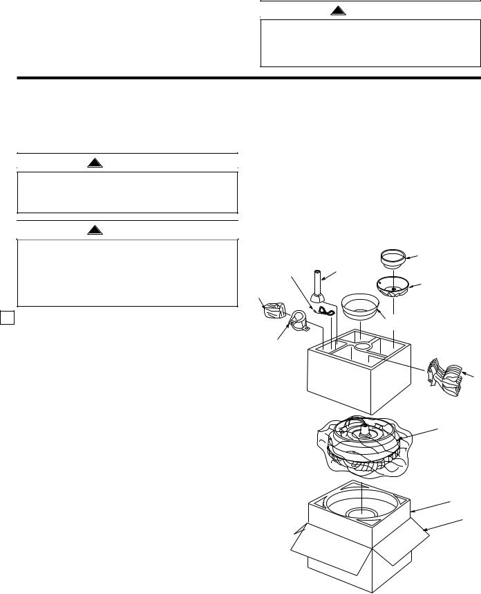
1.Open styrofoam unit containing fan. Remove top half of styrofoam unit. Remove parts and check to see that you have received the following:
a.Fan motor and housing assembly
b.One motor cover
c.One ceiling cover
d.Five blade flanges
e.One hanger ball/downrod assembly
f.One hanger bracket
g.One switch housing cover assembly
h.One uplight lead assembly
i.One loose parts bag containing:
1.One setscrew
2.One 5/32" hex wrench
3.One 3/16” hex wrench
4.Eleven 10-32 x 5/8" oval head screws
5.Two 1” threaded studs
6.Two 1-1/4” threaded studs
7.Four knurled knobs
8.Three wire connectors
9.Four 8-32 x 3/8" flat head screws
10.One pull chain pendant and coupling
11.One hairpin clip
12.One clevis pin
13.Four lockwashers
14.Sixteen 10-24 x 3/8" pan head screws
15.Sixteen flat washers
NOTE: Place the parts from the loose parts bags in small containers to keep them from being lost. If any parts are missing, contact your local retailer or catalog outlet for replacement before proceeding.
NOTE: Fan blades are ordered separately and are packaged in separate carton.
|
|
MOTOR |
|
|
COVER |
UPLIGHT LEAD |
HANGER BALL/ |
|
ASSEMBLY |
|
|
DOWNROD |
SWITCH HOUSING |
|
LOOSE |
ASSEMBLY |
|
|
COVER ASSEMBLY |
|
PARTS BAG |
|
|
CEILING
COVER
HANGER
BRACKET
BLADE
FLANGES
FAN MOTOR AND
HOUSING ASSEMBLY
FOAM PACKING
CARTON
3
Electrical Requirements
Your new ceiling fan will require a grounded electrical supply line of 120 volts AC, 60 Hz, 15 amp circuit.
The outlet box must be securely anchored and capable of withstanding a load of at least 50 pounds.
If you feel that you do not have enough electrical wiring knowledge or experience, have your fan installed by a licensed electrician.
!WARNING
To reduce the risk of fire, electric shock, or personal injury, mount fan to outlet box marked acceptable for fan support, and use screws supplied with outlet box. Mos outlet boxes commonly used for support of light fixtures are not acceptable for fan support and may need to be replaced. Consult a qualified electrician if in doubt.
If your fan is to replace an existing ceiling light fixture, turn electricity off at the main fuse box at this time and remove the existing light fixture.
!WARNING
Turning off wall switch is not sufficient. To avoid possible electrical shock, be sure electricity is turned off at the main fuse box before wiring. All wiring must be in accordance with National and Local codes and the ceiling fan must be properly grounded as a precaution against possible electrical shock.
!WARNING
To avoid fire, or shock, follow all wiring instructions carefully.
Any electrical work not described in these instructions should be done or approved by a licensed electrician.
The Emerson CF2500 Ceiling Fan is designed to be operated from a SR330 Remote Control, from a SW350 Wall Control with a SW375 Receiver, or from other fan/light controls. There are no controls supplied with the ceiling fan. If you are going to control your ceiling fan with a SR330 Remote Control or with a SW350 Wall Control, proceed to “SECTION A”. If you are to control your ceiling fan in any other manner, proceed to “SECTION B”.
Uplight
This fan is supplied with a built-in uplight in the motor housing. This uplight does not have a built-in switch to turn it ON or OFF. A separate switch control must be used to operate the uplight. This can be done with a separate ON/OFF wall switch or one of the many Emerson Fan/Light Controls, such as the SW375 Receiver, SR330 Remote Control or SW95L Controls. The yellow lead supplied with this fan is the power lead for the uplight.
SECTION A
Assembly Instructions
for Installing the CF2500 Ceiling Fan with a SW375 Receiver and a SR330 Remote Control or with a SW350 Wall Control
IF THE CF2500 CEILING FAN IS BEING INSTALLED WITH ANY OTHER CONTROL METHOD, SKIP SECTION A AND GO TO SECTION B TO BEGIN ASSEMBLY INSTRUCTIONS.
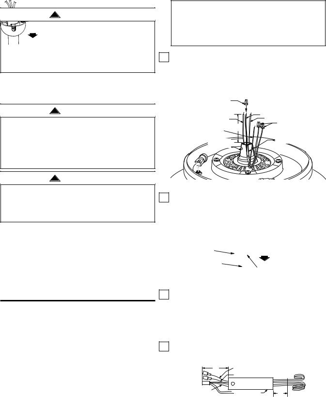
1.Cut the white, blue, and black wires about 3" above the motor coupling (Figure 1). Strip insulation 1/2" from end of wires and install a wire connector on the black wire; this wire will not be used. Remove the wire connectors from the red and brown wires.
INSULATE BLACK
WIRE USING WIRE
CONNECTOR
|
BLACK WIRE |
WHITE WIRE |
BLUE WIRE |
|
REMOVE WIRE |
3" |
CONNECTORS |
YELLOW |
FROM RED AND |
WIRE |
BROWN WIRES |
MOTOR |
MOTOR COUPLING SLOT |
COUPLING |
|
Figure 1
2.Loosen the setscrew in the hanger ball, slide the ball down the downrod, and remove the clevis pin. Then slide the hanger ball off the downrod (Figure 2). Retain all parts for reinstallation in step 11.

 CLEVIS PIN
HANGER BALL
DOWNROD
SETSCREW
Figure 2
3.Push the wiring harness connector and the connector on the blue wire (both supplied with the SW375 Receiver and the SW350 Wall Control), and the connector on the uplight yellow lead assembly (supplied with the fan) through the downrod until they all extend about 4” out of the downrod (Figure 3).
4.Cut all wires approximately 3" from the end of the downrod’. Strip insulation 1/2" from end of wires.
4" |
UPLIGHT YELLOW LEAD ASSEMBLY |
|
|
BLUE WIRE |
CUT HERE |
WIRING |
DOWNROD |
3" |
HARNESS |
||
4 Figure 3

5.Using wiring connectors (supplied), connect the white, red, blue, brown, and yellow wires from the downrod to the white, red, blue, brown and yellow wires of the ceiling fan (Figure 4). Wires must be connected color-to-color.
|
SW375 RECEIVER |
|
|
|
|
|
|
WHITE WIRE |
|
|
BLACK WIRE |
|
||
YELLOW WIRE |
|
|
|
LISTED GENERAL |
TO YELLOW |
|
|
|
|
|
|
|
USE ON/OFF |
|
WIRE |
|
|
|
|
|
|
|
WALL SWITCH |
|
BLUE WIRE |
WHITE WIRE |
|
|
|
|
|
(MUST BE |
||
TO |
RECEIVER |
|
|
USED WITH SR330 |
BLUE WIRE |
CONNECTOR |
|
|
REMOTE CONTROL) |
|
WIRING HARNESS |
|
|
|
|
CONNECTOR |
BLACK |
WHITE |
|
|
BLACK WIRE |
|||
|
|
WIRE |
WIRE |
|
|
DOWNROD |
|
|
TO |
|
|
|
|
|
|
|
|
120V SUPPLY |
|
|
RED WIRE |
|
BLACK |
WHITE |
|
TO RED WIRE |
|
|
|
|
BROWN WIRE |
|
|
|
|
TO BROWN WIRE |
|
|
SW350 |
|
|
|
|
|
|
BLUE WIRE |
|
|
WALL |
|
|
|
CONTROL |
|
|
TO BLUE WIRE |
|
|
|
|
|
|
|
|
BLACK WIRE |
WHITE WIRE |
|
|
|
TO WHITE WIRE |
|
BLACK |
|
|
(NOT USED) |
|
|
||
|
|
|
||
FAN |
YELLOW WIRE |
|
|
|
HOUSING |
TO YELLOW WIRE |
|
|
|
TO
120V SUPPLY
LIGHT FIXTURE
FAN BLADES REMOVED
FOR CLARITY
Figure 4
6.Fold all wires from the downrod into the slot in the motor coupling, slide the downrod down the wires and seat the downrod in the motor coupling. All wires and wire connectors should be placed through the motor coupling slot beneath the downrod (See Figure 5).
7.Align the clevis pin holes in the downrod with the holes in the motor coupling. Install the clevis pin and secure with the hairpin clip. The clevis pin must go through the holes in the motor coupling and the holes in the downrod (Figure 5). Push the straight leg of the hairpin clip through the hole near the end of the clevis pin until the curved portion of the hairpin clip snaps around the clevis pin. The hairpin clip must be properly installed to prevent the clevis pin from working loose.
!WARNING
It is critical that the clevis pin in the motor coupling is properly installed and the setscrew securely tightened. Failure to verify that the pin and setscrew are properly installed could result in the fan falling.
8.Install the setscrew (supplied in the loose parts bag) in the motor coupling and tighten using the 5/32” setscrew wrench (supplied) (Figure 5).
LEADS TO BE |
DOWNROD |
|
POSITIONED IN |
||
SLOT IN MOTOR |
HAIRPIN |
|
COUPLING |
||
CLIP |
||
SETSCREW |
||
|
||
|
MOTOR |
|
|
COUPLING |
|
CLEVIS PIN |
|
 DOWNROD
HAIRPIN
CLIP
 CLEVIS CLEVIS
 PIN PIN
MOTOR COUPLING
Figure 5
NOTE: Make sure the unused black motor lead is capped with a wire connector. Make sure all wire connectors are completely inside motor coupling cover and not pinched between the motor coupling cover and motor.
9.Screw two 1” threaded studs (supplied) into the motor (Figure 6). Leave approximately 7/8” of the stud extending above the motor. Slide the motor cover over the downrod and rotate the cover until the threaded studs protrude; install two knurled knobs (supplied) to secure the cover.

 KNURLED KNOB
MOTOR
COUPLING
COVER
WIRE
CONNECTORS
1" THREADED STUD
MOTOR |
7/8" |
|
Figure 6
10.Position the ceiling cover over the downrod. Be sure the cover is oriented correctly, with the large opening at the top (Figure 7).
5
 Loading...