


Thermetic
TILTING BOILING PANS, ROUND, ELECTRIC
(GU........, KU........)
TILTING FRYING PAN (GP........)
US |
INSTALLATION INSTRUCTIONS |
Doc. 62.9698.01 Edition 1 11.2003

CONTENTS
1. |
|
GENERAL REMARKS ........................................................................................................ |
3 |
2. |
|
PACKAGING / TRANSPORT.............................................................................................. |
3 |
3. |
TECHNICAL DATA / DIMENSIONED DRAWINGS / INSTALLATION PLANS ................. |
3 |
|
3.1 |
TILTING BOILING PANS ................................................................................................................. |
4 |
|
4. |
|
FLOOR GULLIES................................................................................................................ |
5 |
5. |
MOUNTING / POSITIONING / FASTENING IN PLACE / ALIGNMENT............................. |
6 |
|
5.1 |
Positioning ....................................................................................................................................... |
6 |
|
5.2 |
ACCESS TO INSIDE THE CONSOLES AND SUPPORT ................................................................ |
8 |
|
5.3 |
COVERS (PANELS) ......................................................................................................................... |
8 |
|
6. |
|
INSTALLATION................................................................................................................... |
9 |
6.1 |
ELECTRICAL CONNECTION........................................................................................................... |
9 |
|
6.2 |
STEAM AND CONDENSATE CONNECTIONS ............................................................................. |
11 |
|
6.3 |
UNIVERSAL CONTROL PARAMETER SETTINGS ...................................................................... |
13 |
|
6.4 |
THERMACAM / HACCP ................................................................................................................. |
17 |
|
6.5 |
INSPECTION PROCEDURES / TEST OF FUNCTIONS 1................................................................ |
8 |
|
7. |
DECOMMISSIONING / DISMANTLING / DISPOSAL....................................................... |
18 |
|
62.9698.01 |
Page 1 |

1.GENERAL REMARKS
Responsibility
The setting up, adjustment and initial commissioning of appliances must be carried out in accordance with the manufacturer's instructions and may only be done by authorised personnel. The installations for the electricity, steam, condensate, hot water, gas and water supplies as well as ventilation must be laid or fitted by approved installation contractors in accordance with specific national and local regulations. The installation contractors are responsible for the correct layouts and installations in conformity with all safety regulations. The warning signs and specification plates fitted to the appliances must be strictly adhered to.
Validity
These instructions for installation refer to the THERMETIC tilting appliance program with appliances of different sizes: tilting boiling pans, tilting braising pans and tilting pressure braising pans.
Dimensioned drawings and installation plans of this document are only for information purpose to the installers. These plans may not be used for planning or projecting kitchens.
Tests/certificates
All electric appliances are tested by testing institutes. They fulfil standards UL 197 as well as NSF4 1999 and NSF 12 1992 (Chilltherm). The appliances are marked with the UL marking on the specification plate.
2.PACKAGING / TRANSPORT
Types of packaging
Various types of packaging are used dependent on country of destination. All versions of these appliances are transported on a wooden frame or floor, are affixed to these with plastic straps and located with wooden strips to prevent slipping.
Destination |
Overseas: |
Version: |
Heavy, crate closed |
Floor: |
Wooden floor |
Floor fixing: |
|
Side and cover frame: |
|
Water and dust protection: |
Plastic film |
Physical outer protection: |
Closed crate |
Held together by: |
External steel banding |
Transport: |
Forwarder |
Stack ability: |
max. 4 appliances |
Packaging markings
The external surfaces of the packaging have the following markings which must be strictly adhered to:
•Forwarding label with the following information:
-Delivery company
-Delivery company's order number
-Customer's order number if available
-Delivery address
-Package number
-Net weight in kg
-Gross weight in kg
-External dimensions of the packaging
•Handling stickers with pictograms
- Umbrella |
= |
Keep dry; the packaged appliance |
- Glass |
= |
may not be stored outdoors |
Contents fragile |
||
- Arrow pointing up |
= |
Only transport and store the |
- Stacking number |
= |
appliance in this position |
Number of appliances that can be |
||
- Ice crystal and roof = |
stacked (1 = cannot be stacked) |
|
Protect against frost |
||
Transport weights
The precise gross and net weight is given on the forwarding label. Due to the wide range of appliances, only the maximum weights possible for the "European light" version are summarized below:
Tilting boiling pans |
max. gross weight |
|
max. net weight |
|||
.U........ |
|
kg |
lb. |
|
kg |
lb. |
|
|
|
|
|
|
|
080 LT |
(21.1 gal) |
215 |
474 |
195 |
430 |
|
|
|
250 |
551 |
230 |
507 |
|
100 LT |
(26.4 gal) |
|||||
|
|
290 |
639 |
270 |
598 |
|
150 LT |
(39.4 gal) |
|||||
|
|
380 |
838 |
360 |
794 |
|
200 LT |
(52.8 gal) |
|||||
|
|
410 |
904 |
390 |
860 |
|
300 LT |
(79.3 gal) |
|||||
|
|
450 |
992 |
420 |
960 |
|
400 LT |
105.7 gal) |
|||||
|
|
|
|
|||
|
|
|
|
|||
Tilting braising pans |
max. gross weight |
|
max. net weight |
|||
.P........ |
|
kg |
lb. |
|
kg |
lb. |
|
|
|
|
|
|
|
060 LT |
(15.9 gal) |
230 |
507 |
|
210 |
463 |
080 LT |
(21.1 gal) |
260 |
573 |
|
240 |
529 |
100 LT |
(26.4 gal) |
290 |
639 |
|
270 |
595 |
|
|
|
|
|
|
|
Packaging dimensions
The precise external dimensions of the packaging are given on the forwarding label attached to the outside of the packaging. The maximum dimensions of the "European light" style of packaging are given below:
Appliance size |
|
Width |
Depth |
Height |
|||
LT |
|
mm |
inch |
mm |
inch |
mm |
inch |
|
|
|
|
|
|
|
|
Tilting boiling pans 80, 100 |
(1) |
1400 |
55.1 |
800 |
31.5 |
1250 |
49.2 |
Tilting braising pans 60 |
(2) |
1400 |
55.1 |
1200 |
47.2 |
1100 |
43.3 |
Tilting pressure braising pans |
|
|
|
|
|
|
|
60, 90 |
|
|
|
|
|
|
|
|
|
1500 |
59.1 |
1000 |
39.4 |
1300 |
51.2 |
Tilting boiling pans 150 |
(1) |
||||||
|
(2) |
1500 |
59.1 |
1300 |
51.2 |
1100 |
43.3 |
|
|
1600 |
23.6 |
1100 |
43.3 |
1400 |
45.1 |
Tilting boiling pans 200 |
(1) |
||||||
Tilting braising pans 80 |
(2) |
1600 |
63 |
1400 |
55.1 |
1200 |
47.2 |
|
|
1700 |
66.9 |
1100 |
43.3 |
1500 |
59.1 |
Tilting boiling pans 300, 400 |
|
||||||
Tilting braising pans100 |
(1) |
1700 |
66.9 |
1500 |
59.1 |
1200 |
47.2 |
Tilting pressure braising pans |
(2) |
|
|
|
|
|
|
100, 150 |
|
|
|
|
|
|
|
|
|
|
|
|
|
|
|
(1)without floor support for wall mounting
(2)with floor support for floor mounting
Handling
Both packaged as well as unpacked appliances are best lifted and transported whenever required with a pallet truck which is inserted into the wooden frame or under the wooden base. This applies to both the loading and unloading of trucks as well as to handling operations on the installation site.
For handling by a crane, the unpacked appliances do not have any specific lifting points to which they can be attached. It is necessary to wrap two straps or ropes around the appliance when lifting is required. Wrapping straps or ropes around the appliance may only be done at the sides and not round the front and the rear. The straps or ropes should be arranged approximately 150 mm (5.9“) from the outer edges.
3. TECHNICAL DATA / DIMENSIONED DRAWINGS / INSTALLATION PLANS
These illustrations are not intended for the planning and laying of the supply lines in the building.
62.9698 |
Page 3 |
3.1TILTING BOILING PANS
Style of mounting (optional Tilting
Control system
Stirring system (optional) Protective system
Floor mounting with floor supports with consoles.
Motor tilting with lifting motor
PROCESS COMFORT control system with cooking temperature control and programmable cooking and starting time.
Manual control for steam heated boiling pans.
Grid stirrer with and without scraper, blade stirrer.
hose proof IP X5
Net content in litres, max. capacity |
80 - 400 |
Elect. motor tilting |
|
Wattage in kW |
0,1 |
Voltage (V), Current in A |
230V/1~N,60 Hz, 0,7 A |
Stirring system |
|
Wattage in kW |
0,37 |
Voltage (V), Current in A |
208V/3~N, 60 Hz, 2.1 A, |
|
240V/3~N, 60 Hz, 1.8 A |
|
480V/3~N, 60 Hz, 0.9 A |
CHILLTHERM |
0,4 |
Wattage in kW, |
|
Voltage ('), Current in A |
208V/3~N, 60 Hz, 3.9 A, |
|
240V/3~N, 60 Hz, 3.4 A, |
|
480V/3~N, 60 Hz, 1.7 A |
3.1.1 Electrically heated tilting boiling pans (.U........))
Heating |
80 LT, |
100 LT, |
150 LT, |
200 LT, |
300 LT, |
400 LT, |
|
electric |
electric |
electric |
electric |
electric |
electric |
Wattage |
18,2 |
18,2 |
24,2 |
30,2 |
36,2 |
48,2 |
kW |
|
|
|
|
|
|
Voltage |
52 |
52 |
70 |
85.3 |
102 |
119 |
208V/3~N |
|
|
|
|
|
|
Current A |
|
|
|
|
|
|
Voltage |
44 |
44 |
60 |
74.5 |
89 |
117.5 |
240V/3~N |
|
|
|
|
|
|
Current A |
|
|
|
|
|
|
Voltage |
23 |
23 |
30 |
38 |
44.5 |
59 |
480V/3~N |
|
|
|
|
|
|
Current A |
|
|
|
|
|
|
|
|
|
|
|
|
|
Additional loads are listed in 3.1.
Dimensioned drawings for tilting boiling pans (.U........)
L Length to floor gully N Depth of floor gully
|
|
|
Pan size in litres |
|
|
|
|
80 |
100 |
150 |
200 |
300 |
400 |
|
|
|
Dimensions mm |
|
|
|
A |
1200 |
1200 |
1300 |
1400 |
1500 |
1500 |
B |
1073 |
1096 |
1124 |
1289 |
1352 |
1434 |
C |
1034 |
1060 |
1090 |
1234 |
1290 |
1290 |
D |
579 |
640 |
710 |
800 |
900 |
900 |
E |
385 |
395 |
465 |
490 |
570 |
720 |
F |
900 |
900 |
900 |
1900 |
900 |
900 |
G |
476 |
450 |
420 |
376 |
320 |
3 20 |
H |
80 |
88 |
97 |
110 |
110 |
110 |
J |
680 |
680 |
680 |
780 |
780 |
780 |
K |
900 |
900 |
900 |
1000 |
1000 |
1000 |
L |
710 |
710 |
710 |
810 |
810 |
810 |
M |
330 |
330 |
330 |
430 |
430 |
430 |
N |
1000 |
1000 |
1000 |
1200 |
1200 |
1200 |
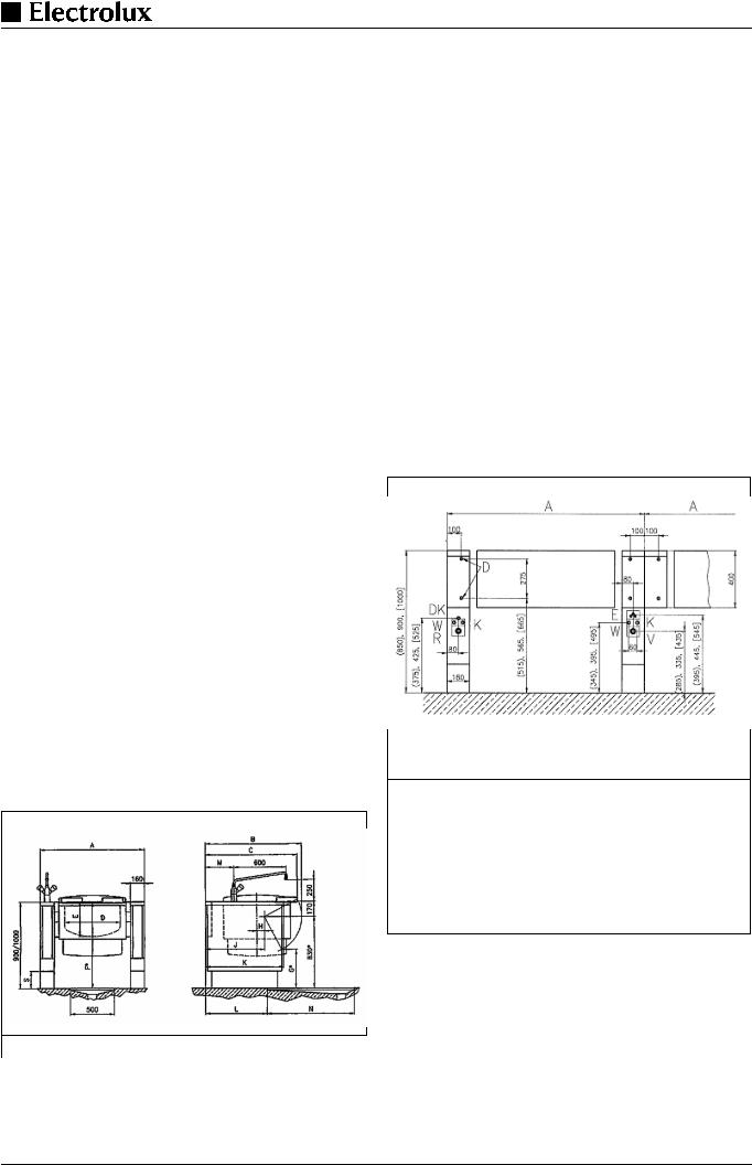
Installation plans for tilting boiling pans (.U........), tilting frying pans (.P........), tilting braising pans (.X........)
R
A Width of appliance (see dimensioned drawing)
EElectrical cable protruding W from wall
VSteam or hot water supply, K Sandvik coupling, nominal width 25 mm
Condensate drain or hot water return,
Y Sandvik-coupling, nominal width 25 mm
Hot water connection G 1/2", NW15
Cold water connection G 1/2", NW15
Fig. 2 Installation plans for tilting boiling pans, tilting frying pans, tilting braising pans
Fig. 1 Dimensioned drawings for tilting boiling pans
Page 4 |
62.9698 |

Installation plans CHILLTHERM for tilting boiling pans
.U........
A Width of appliance (see |
N Cooling water inlet |
||
dimensioned drawing) |
O Cooling water outlet |
||
E Electrical cable protruding |
|||
Z Sandvik-coupling, nominal |
|||
from floor or wall |
width 25 mm |
||
1 |
Mains supply |
||
W Hot water connection G |
|||
2 |
Potential free contact |
||
1/2", NW15 |
|||
3 |
Energie optimization |
||
K Cold water connection G |
|||
4 |
ThermaCam inlet |
1/2", NW15YConnection G |
|
5 |
ThermaCam outlet |
1/2" |
|
S Steel or masonry plinth 100 |
|||
V Steam or hot water supply, |
|||
R Condensate drain or hot |
- 200 mm |
||
|
|||
water return
Fig. 3 Installation plan CHILLTHERM for tilting boiling pans
3.1.2Directly steam-heated boiling pans (.U1......,
.U2......, .U3......, .U4......)
Tilting boiling pan with direct heating with saturated steam, overpressure 0.8 bar (11.6 psi), temperature 244°F (118°C).
Voltage for the control and tilting systems: 230V/1~N, 60 Hz.
Type |
80 LT, |
100 LT, |
|
150 LT, |
200 LT, |
300 LT, |
400 LT, |
|
|
steam |
steam |
|
steam |
steaS |
steam |
steam |
|
External steam in |
40 |
48 |
|
63 |
77 |
100 |
122 |
|
kg/h |
|
|
|
|
|
|
|
|
|
|
|
|
|
|
|
|
|
Heating power in |
24,5 |
29 |
|
38 |
47 |
61 |
75 |
|
kW |
|
|
|
|
|
|
|
|
|
|
|
|
|
|
|
|
|
Wattage in kW |
0,20 |
|
|
|
|
|
|
|
Voltage Current in |
120V/3~N, 60 |
Hz, 2.0 A, |
|
|
|
|
||
A |
208V/3~N, 60 |
Hz, 1.2 A, |
|
|
|
|
||
|
240V/3~N, 60 |
Hz, 1.0 A, |
|
|
|
|
||
|
480V/3~N, 60 |
Hz, 0.5 A |
|
|
|
|
||
|
|
|
|
|
|
|
|
|
Stirring system see 3.1.
Dimensioned drawings see 3.1.1.
Installation plan for floor and wall mounting see 3.1.1.
3.1.3TILTING FRYING PANS (.P........)
Model (optional) Pan bottom made of steel or chrome-nickel plated steel
Style of mountingFloor mounting with floor support with console.
Tilting |
Motor tilting with lifting motor |
Control system |
PROCESS COMFORT control system with |
|
pan-base and cooking temperature control |
|
and programmable cooking and starting |
|
time. |
Tilting Frying Pans
Type |
060 LT, |
080 LT, |
100 LT, |
|
electric |
electric |
electric |
|
|
|
|
Dimension A (mm) |
1200 |
1400 |
1600 |
(inch) |
47.2 |
55.1 |
63 |
|
|
|
|
Braising surface (mm) |
600 x 600 |
800 x 600 |
1000 x 600 |
(inch) |
23.6x23.6 |
31.5 |
39.8 |
Pan depth in (mm) |
200 |
200 |
200 |
T(inch) |
7.9 |
7.9 |
7.9 |
|
|
|
|
Net content (litres) |
63 |
84 |
104 |
(gal) |
16.4 |
22.2 |
27.5 |
max. capacity |
|
|
|
|
|
|
|
El. heating power in kW |
12.2 |
15.2 |
18.2 |
|
|
|
|
Voltage 208V/3~N |
34.5 |
42.8 |
42.8 |
Current A |
|
|
|
|
|
|
|
Voltage 240V/3~N |
30 |
37.1 |
37.1 |
Current A |
|
|
|
|
|
|
|
Voltage 480V/3~N |
15.2 |
18.8 |
22.5 |
Current A |
|
|
|
|
|
|
|
Dimensioned drawings
H Height for all types 900 mm (35.4“)
S Height of feet / wheel 200 mm (7.9“)
Fig. 4 Dimensioned drawings
Tilting frying pans
Installation plan see 3.1.1.
4.FLOOR GULLIES
In the case of tilting appliances, floor gullies with loose gratings and floor drains which serve as drains when cleaning are provided for near to the outlet. Floor gullies can be designed for a single appliance or for a whole group of appliances. There is a very wide variety of types and sizes. Please consult the relevant installation plans for information concerning layout and type.
In general, the floor gullies with their drains are concreted into the floor by the builder.
APan sizes 80 to 150 litres; Grating 500 x 1000
mm(19.7x39.4“)
BPan sizes 200 to 400 litres; Grating 600 x 1200
mm(23.6x47.2“)
Fig. 5 Sample dimensions of individual floor gullies for tilting boiling pans without drain valves.
62.9698 |
Page 5 |

Fig. 6 Typical, floor gully for a single appliance with a siphon
(S)made of stainless steel (728 342 984)
5.MOUNTING / POSITIONING / FASTENING IN PLACE / ALIGNMENT
In principle, the appliance must be installed in its scheduled location in accordance with the valid plans. The appliance is scheduled for connection to fixed powerand water supplies. The installation dimensions are given on the plans.
The appliances are suitable for setting up as single appliances or as a group of appliances. They can be set up freely in the room, side by side, at the side and/or at the back against a wall.
.
Removal of the packaging:
The packaging should not be removed until immediately before the appliance is to be set up in place. All side and top packaging parts as well as the fastening elements must be removed in sequence. The appliance should remain on its wooden transport frame or base until at the site for installation.
5.1Positioning
Transport the appliance on its wooden frame to a point directly in front of where it is to be set up. The installation connections protruding from the floor should be at the side as close as possible to the wooden frame.Slide the appliance off the wooden frame so that all the installation connections are within the appliance.
Tip until the appliance touches the floor. Raise the front and pull out the wooden frame.
Distances/walls
Valid only for braising pans and pressure braising pans.
These may not be positioned against combustible walls. If an appliance is set up next to or against temperature-sensitive furniture or similar, a safety gap of approximately 50 mm (2“) should be maintained or some form of heat insulation fitted. When setting up an appliance in the close vicinity of walls, partitions, kitchen equipment, decorative cladding, etc., it is recommended that the latter are made of incombustible material or that they are clad in a suitable, incombustible material or tiled. The regulations governing fire protection must be adhered to as closely as possible.
Preparation for fastening in place
Before the appliance is brought to the correct place and put in position, the following connection points must be prepared dependent on the type of appliance:
•Fastening elements, i.e. drilling holes and inserting plugs. Explanations for this are included in the relevant sections under "Fastening".
•Remove the Sandvik connectors, nominal width 25 (1“), from the hoses and weld them onto the supply lines provided on-site (see § 6.2.).
•Prepare the water connections and, possibly, fit a shut-off valve.
Setting up
The appliance should be transported to the place where it is to be set up in accordance with § 2
Lower the appliance carefully and slide it into the correct final position.
wall, which is installed at the equipment back of the appliance.
Appliance on feet.
Fig. 7 Appliance foot
DTurn the lower part of the feed (FU / Fig. 7) to adjust the appliance high.
The feed are adjustable from 100 to 200 mm. A high of 200 mm can be recommended and results in an appliance high of 900 mm.
Note:
Adjustment of the legs shall provide an unobstructed clearance of minimal 150 mm and maximal 200 mm beneath the unit due to sanitary and stability aspects.
The lower part of the foot must not be unscrewed too far. The exposure of threads is prihibited.
Page 6 |
62.9698 |
 Loading...