


AOS061G
Electrolux Professional S.p.A.
Ovens Platform Customer Support
Technical Training & Service
AOS OVENS - Service Manual
(595889300 - ENG)
File: AOS service manual (ENG).009 ©Copyright 2002 by Electrolux Professional P. 1/43
AOS OVENS
- Service Manual -
CONTENTS:
This document contains the information about parameters that can be
read and/or modified by means of user interface, service utilities, ...
PROJECT REF:
AOS ovens
AUTHORS:
A.Canova
CONTRIBUTION BY:
D. Vadori
F. Fingolo
F. Ornella
S. Gant
DOCUMENT HISTORY:
Rel. Date: File: Author: Note:
005 06/04/2004 AOS service manual (ENG).005 A. Canova
New features from firmware 2.7, 2/1
gas ovens, added appendix B-C-D
006 05/07/2004 AOS service manual (ENG).006 A. Canova
New calibrations for AOS061G and
AOS101G, updated appendix C-D,
added appendix E-F-G
007 18/02/2005 AOS service manual (ENG).007 A. Canova
Updated appendix D, calibration of
AOS061G and added appendix H-I
008 13/06/2005 AOS service manual (ENG).008 A. Canova
Updated calibrations for AOS101G,
AOS201G, AOS102G, AOS202G;
firmware 2.80
009 14/09/2006 AOS service manual (ENG).009 A. Canova
Firmware 2.90; new value for hAcA for
AOS201G-G20 and for Stbo for
AOS101G-G25; new procedure for
param. programming, updated
appendix D, F; added appendix J

Electrolux Professional S.p.A.
Ovens Platform Customer Support
Technical Training & Service
AOS OVENS - Service Manual
(595889300 – ENG)
File: AOS service manual (ENG).009 ©Copyright 2002 by Electrolux Professional P. 2/43
INDEX
1. PROGRAMMING THE DEFAULT PARAMETERS................................................................................4
2. ADVANCED PROGRAMMING.........................................................................................................5
3. BY-PASS CALIBRATION (ONLY FOR LEV. B OVENS) ......................................................................6
4. LAMBDA PROBE CALIBRATION (ONLY FOR LEV. A OVENS)............................................................7
5. OFFSET CALIBRATION (ONLY FOR LEV. A OVENS)........................................................................8
6. ERROR CODES ...........................................................................................................................8
6.1. ERRORS ..................................................................................................................................8
6.2. WARNINGS...............................................................................................................................8
7. FIRMWARE VERSION...................................................................................................................9
8. WORKING TEMPERATURES .........................................................................................................9
9. SERVICE UTILITIES......................................................................................................................9
9.1. UTILITIES THAT CAN BE ACTIVATED WITH OVEN SWITCHED ON....................................................9
9.2. UTILITIES THAT CAN BE ACTIVATED IN PARAMETER PROGRAMMING..........................................10
10. SELECTION OF THE LANGUAGE FOR THE RECIPE MENU (LEV. A).................................................11
11. CLEANING CYCLE (LEV. A OVENS).............................................................................................11
12. CYCLES, UTILITIES, IMPORTANT PARAMETERS...........................................................................12
13. GAS SYSTEM............................................................................................................................13
13.1. GAS VALVE.........................................................................................................................14
13.2. OFFSET PRESSURE CALIBRATION ........................................................................................16
13.3. USE OF MANOMETER (FOR OFFSET PRESSURE MEASURE).....................................................16
14. CHANGE OF THE MICROPROCESSOR BOARD..............................................................................18
APPENDIX A – WATER BOILING POINT.......................................................................................19
APPENDIX B – CONTACTORS DIAGRAM ....................................................................................20
APPENDIX C – CONNECTIONS ON MAIN BOARD.......................................................................21

Electrolux Professional S.p.A.
Ovens Platform Customer Support
Technical Training & Service
AOS OVENS - Service Manual
(595889300 – ENG)
File: AOS service manual (ENG).009 ©Copyright 2002 by Electrolux Professional P. 3/43
APPENDIX D – TROUBLESHOOTING...........................................................................................24
APPENDIX E – LAMBDA PROBE...................................................................................................29
APPENDIX F – PARAMETER DESCRIPTIONS .............................................................................30
APPENDIX G – GAS CALIBRATIONS............................................................................................33
APPENDIX H – WATER TREATMENT ...........................................................................................39
APPENDIX I – CONNECTION TO HACCP SYSTEM......................................................................41
APPENDIX J – RELAY DESCRIPTIONS ........................................................................................42
Electrolux Professional S.p.A.
Ovens Platform Customer Support
Technical Training & Service
AOS OVENS - Service Manual
(595889300 – ENG)
File: AOS service manual (ENG).009 ©Copyright 2002 by Electrolux Professional P. 4/43
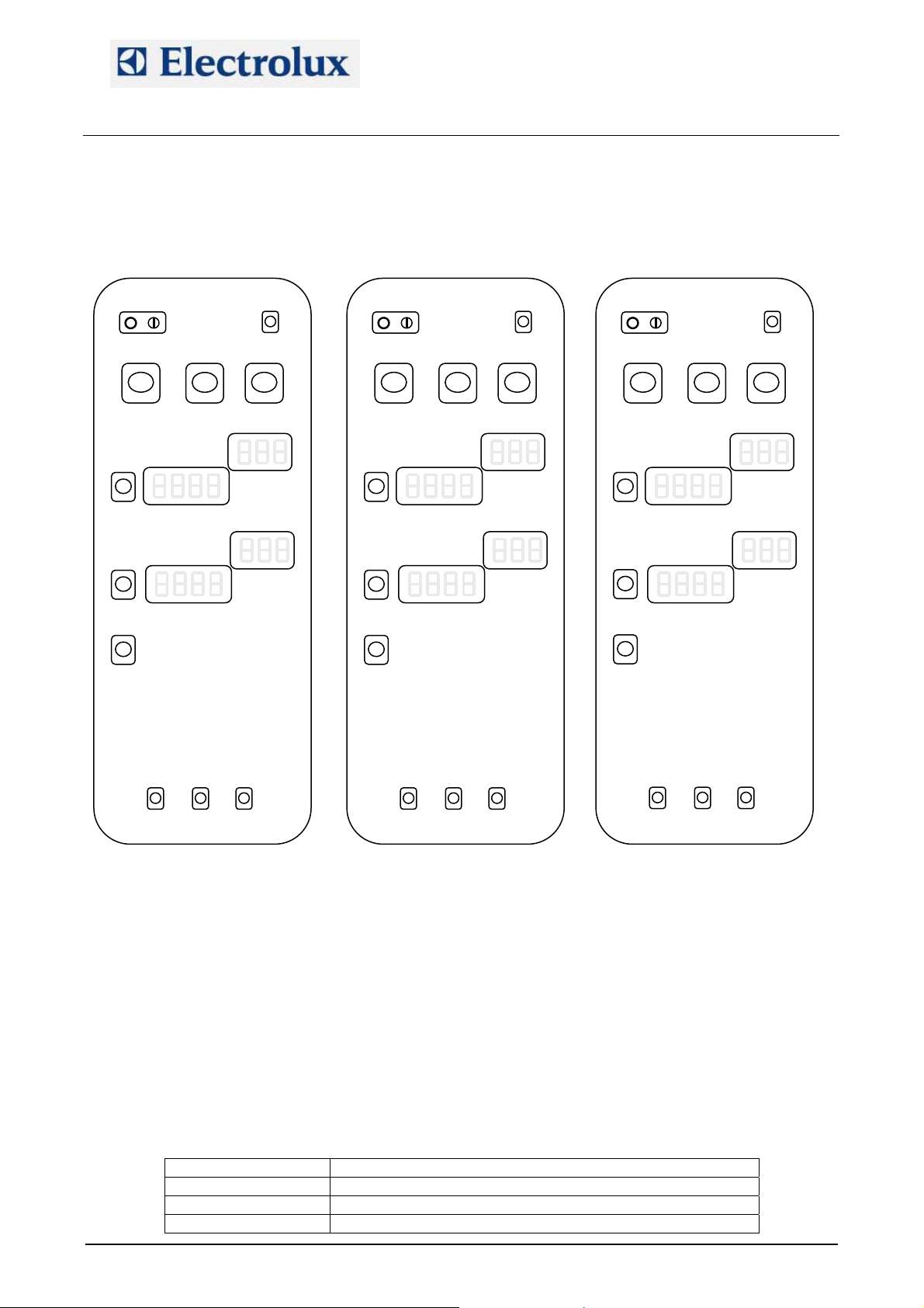
1. Programming the default parameters
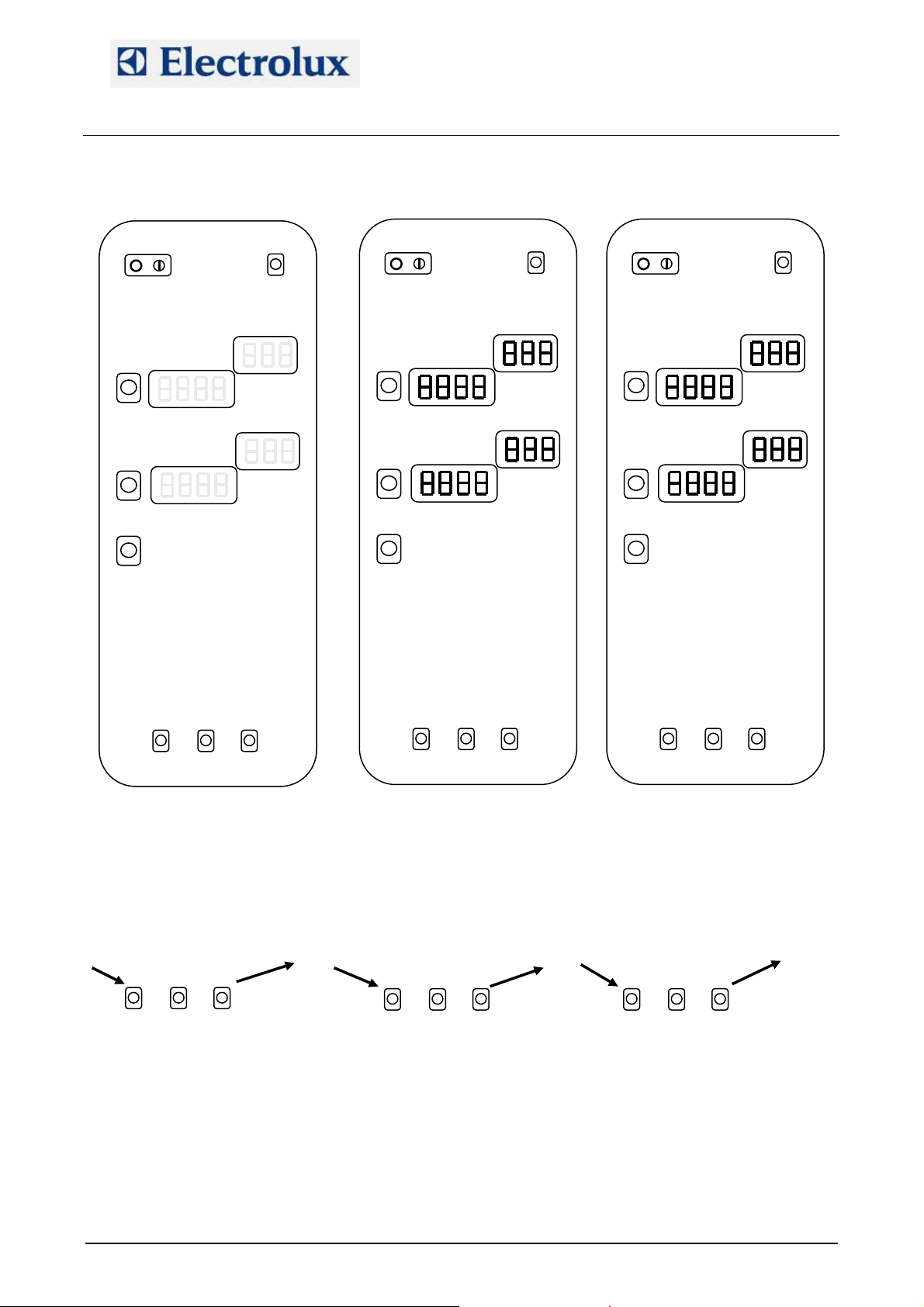
Switch on the oven (fig. 1).
Just after the switching on, a lamp test will take place (fig 2).
At this point, during the lamp test phase, press the external service buttons (fig.3) till you hear a beep.
At this point press the right buttons till you hear a beep (fig. 4).
Press then the left service buttons till the beep (fig. 5).
At this point release the left buttons keeping pressed the middle one (fig. 6) till you hear 2 beeps.
Release the middle button and on the temperature display you will see “PdEF”: the oven will switch off and
on automatically.
Fig. 4 Fig. 5 Fig. 6
1
1
1 2
1
Fig. 2
Fig. 3
Fig. 1

Electrolux Professional S.p.A.
Ovens Platform Customer Support
Technical Training & Service
AOS OVENS - Service Manual
(595889300 – ENG)
File: AOS service manual (ENG).009 ©Copyright 2002 by Electrolux Professional P. 5/43
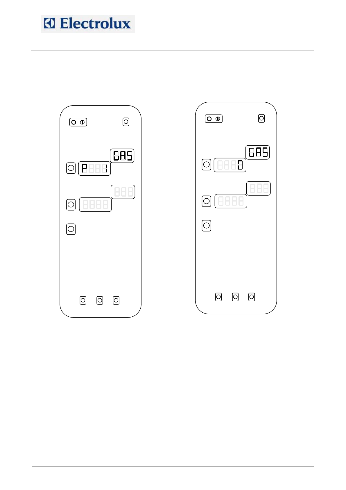
2. Advanced programming
The procedure to enter in advanced programming is similar to the procedure for programming the defaults
parameters.
Switch on the oven (fig. 7).
Just after the switching on, a lamp test will take place (fig. 8).
At this point, during the lamp test, press the external service buttons (fig.9) till you hear a beep.
At this point press the right buttons till you hear a beep (fig. 10).
Press then the left service buttons till the beep (fig. 11).
Release the button and on the temperature display you will see “P 1” while on the little display the name of
the parameter will appear (fig. 12).
With the external service buttons it is possible to scroll the list of the parameters.
Fig. 7
1
1
1
Fig. 8
Fig. 9
Fig. 10 Fig. 11
Electrolux Professional S.p.A.
Ovens Platform Customer Support
Technical Training & Service
AOS OVENS - Service Manual
(595889300 – ENG)
File: AOS service manual (ENG).009 ©Copyright 2002 by Electrolux Professional P. 6/43
Pressing the middle button it is possible to see the value of the parameter (fig. 13) and pressing at this
point the external buttons it is possible to modify the value. Press again the middle button returning to the
displaying of the number of the parameter to store the new value.
Switch off the oven to exit from programming.
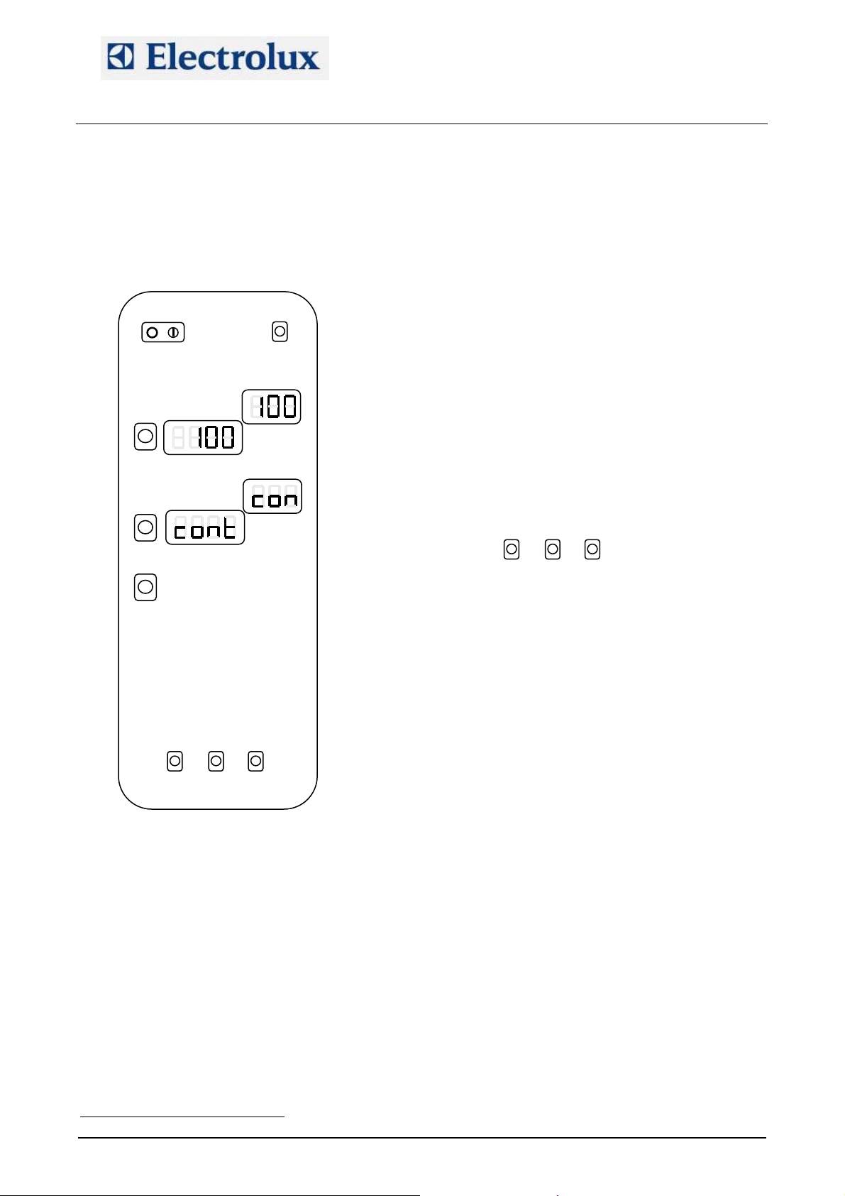
3. By-pass calibration (only for lev. B ovens)
In order to calibrate the by-pass probe on lev. B oven, follow these steps:
1) Switch on the oven
2) Enter in parameter programming and set parameters cort and OCA1 to 0
3) Exit from programming and switch on again the oven
4) Wait for the end of the pre-heating cycle
5) Select a steam cycle (100 °C)
6) Select continuous time (indication “cont” on time display)
7) Press and hold down the left service buttons and at the same time press the START button (fig. 14);
the oven will give a long beep
8) Release the service buttons and wait for the stabilization of the temperature reading by the by-pass
probe
9) When the temperature has stabilized, press the three service button together in order to memorize the
value (fig. 15); the oven will confirm the storing with a long beep
Fig. 12
Fig. 13
Electrolux Professional S.p.A.
Ovens Platform Customer Support
Technical Training & Service
AOS OVENS - Service Manual
(595889300 – ENG)
File: AOS service manual (ENG).009 ©Copyright 2002 by Electrolux Professional P. 7/43
10) Allow the oven to work for several minutes in steam mode checking the oven cavity temperature, which
should stabilize at the water boiling point. If this reading is greater or less than the correct water boiling
point
TPF
1
FPT, a corrective value can be stored in the parameter OCA1. From firmware release 2.90, pushing
the 3 service buttons to store the bypass temperature, the microprocessor will calculate and store also
the value of OCA1.
11) Set parameter cort to 1.
12) Set the altitude above sea level of the site on paramet er SEAL
4. Lambda probe calibration (only for lev. A ovens)
The calibration of the lambda probe is necessary (from firmware 2.6) for the right working of the oven in
case of cycle with set point under 100 °C. With this procedure we have to find the point of 0% of humidity.
The procedure is done in a way similar to the by-pass calibration. These are the steps:
1) Set an hot air cycle, 150 °C, time over 15 minutes, open flap;
2) Start the cycle pressing together the left and middle service buttons and the START button. The
oven will give a long beep;
3) Wait around 10-15 minutes to dry completely the cavity;
4) Close the flap and wait around 20 seconds to stabilize the humidity inside the cavity;
5) To store the value press together the 3 service buttons. The oven will confirm with a long beep.
6) Stop the cycle with the START button.
This calibration is very important and has to be done with care. If the dry point (0% of humidity) is not
correctly stored, the reading of the relative humidity could be overestimated or underestimated.
TP
1
PT See Appendix A
Fig. 14
Fig. 15

Electrolux Professional S.p.A.
Ovens Platform Customer Support
Technical Training & Service
AOS OVENS - Service Manual
(595889300 – ENG)
File: AOS service manual (ENG).009 ©Copyright 2002 by Electrolux Professional P. 8/43
5. Offset calibration (only for lev. A ovens)
In order to adjust the offset of the cavity probe, enter in parameter programming and set parameters cort
and OCA1 to 0.
Then run a steam cycle for several minutes and check the cavity temperature, which should stabilize at the
water boiling point. If the stabilized cavity temperature is less or greater than the correct water boiling
point
TPF
2
FPT, a corrective value can be stored in parameter OCA1.
After this, set parameter cort to 1and set parameter SEAL (altitude above sea level).
6. Error codes
Errors can be divided into 2 categories: errors (they stop the appliance) and warnings (they do not stop the
appliance)
6.1. Errors
EE2P: Communication error with the EEPROM
E---: If the controller detects one or more parameters which have values not permitting the minimum
operational requirements, an error code will appear on the display, i.e. “E---” followed by the parameter
number. Enter the programming mode and set the correct value according to the parameter list.
EtUC: Cavity over temperature; cavity temperature exceeded value stored in parameter cot.
EtUB: Boiler over temperature; boiler temperature exceeded value stored in parameter bot.
EFUN: Activation of the thermal protection of the motor. On the little temperature display it will appear “UP”
or “DOWN” according it is the thermal protection of the upper motor (and the motor of 6-10 grid ovens) or
lower motor on 20-grid oven. The thermal protection has an automatic reset but in order to continue with
the cooking process, parameter ALFn has to be reset to 0.
Etc: Tripping out of cavity limiter
Etb: Tripping out of boiler limiter
ESCH or ETBR: Over temperature on the electronic board; check the cooling fan and the ventilation
openings on the bottom of the control panel.
Ept1: cavity probe in open circuit (only the steam cycle – 100 °C can be selected)
Ept2: boiler probe in open circuit (only hot air cycle can be selected)
Ept3: meat probe in open circuit (only time cooking can be selected)
Ept4: by-pass probe in open circuit (only hot air, regeneration or low temperature steam cycle can be
selected)
Ept8: NTC probe in short or open circuit
ECAD: A/D converters not working
E PM: Communication error with PWM system
E SL: Water level probe error. If the boiler heating elements or burners are on for a tiem over that one
defined in parameter tbon without a water charging phase, this error message is activated. To reset it,
parameter ALFn has to be reset to 0.
burn CAUP: Reset of cavity burner (gas oven) (the upper one in the 20 grid ovens)
burn CAdo: Reset of lower cavity burner (gas oven) in 20 1/1 and 2/1 ovens
burn boUP: Reset of boiler burner (gas oven) (the upper one in 20 2/1 ovens)
burn bodo: Reset of lower boiler burner (gas oven)
6.2. Warnings
EH2O: Before the starting of the cleaning system and during its working, there are some check points of
the water pressure. If the water pressure is too low this warning message appear on the display. Check
the water pressure (1.5÷2.5 bar), check the correct working of the water pressure switch, check if there are
obstructions on the cleaning water inlet pipe (its inner diameter must be 20 mm). From firmware release
2.50, EH2O is a warning message and no more an error causing the stopping of the cleaning cycle.
EFLP: Cavity ventilation flap failure; check the motoreducer or the micro switch that detects the close
position of the flap. If the motoreducer does not close the flap within the time set in parameter FLto, EFLP
error appears.
ECLO: Clock error, it appears if the clock was never adjusted
EPrG: Error in reading the phases of a multiphase recipe
TP
2
PT See Appendix A
Electrolux Professional S.p.A.
Ovens Platform Customer Support
Technical Training & Service
AOS OVENS - Service Manual
(595889300 – ENG)
File: AOS service manual (ENG).009 ©Copyright 2002 by Electrolux Professional P. 9/43
EIND: Error in reading the index of the recipes
EDES: Error in reading the description of a recipe
ERAM: Communication error with the RAM
nFIP: Communication error of recipe display
DOOR: Open door (from firmware 2.6 only the led on the control panel switches on)
FILL: Safety level probe of the boiler out of water
PrEH: Preheating phase of the boiler; from firmware 2.90 it indicates the preheating phase of the cavity if
the warning message appears on temperature display.
OPEN: boiler drain activated
COOL: Cavity cooling phase
dEt: low level of detergent
rAI: low level of rinser
rCLN: request for a cleaning cycle (manual or automatic); parameter FCLn is set to a value different from
da 0.
LOAD: end of pre-heating phase of the cavity; if nothing is done, the cavity is maintained at the pre-heating
set-point.
Strt: push START button.
7. Firmware version
In order to check the version of the firmware, switch on the oven and wait for the lamp test and the end of
the start-up phase (4 lines on the temperature display). When on the temperature display, the actual cavity
temperature appears, pressing the three service buttons together on the display temperature the firmware
version will appear. Pressing again these buttons, the board temperature will be displayed.
8. Working temperatures
While the oven is working, it is possible to see the temperature of the several probes pressing the service
buttons. See the following figures:
9. Service utilities
From firmware release 2.50, some useful utilities are present for troubleshooting and diagnostic of the
oven.
These additional features can be divided in 2 set: utilities that can be activated with the oven switched on,
utilities that can be activated with the oven in parameter programming
9.1. Utilities that can be activated with oven switched on
With the oven switched on and not in a cooking phase, pressing simultaneously the following buttons it is
possible to activate the detergent, rinser pumps and water valve of the cleaning system:
• Steam cycle, combi cycle, temperature buttons (fig. 20): activation of detergent pump
• Steam cycle, combi cycle, time buttons (fig. 21): activation of rinser pump
• Steam cycle, combi cycle, utility buttons (fig. 22): activation of water valve of the cleaning system
Fig. 17
Temperatura del by-pass
Fig. 16
Temperatura del boiler
Fig. 18
Temperatura dello spillone
Fig. 19
Temperatura della scheda
Electrolux Professional S.p.A.
Ovens Platform Customer Support
Technical Training & Service
AOS OVENS - Service Manual
(595889300 – ENG)
File: AOS service manual (ENG).009 ©Copyright 2002 by Electrolux Professional P. 10/43
These routines are achievable only on lev. A ovens, i.e. with the parameter dCLn set to 0, closed door and
cavity temperature less than 80 °C and, from firmware release 2.90, with the oven not blocked with
password.
9.2. Utilities that can be activated in parameter programming
• Pressing the steam cycle and hot air cycle buttons, all the output relays are sequentially activated and
on the time display it will be displayed the activated relay with the message do1, do2, ... (dox=RLx on
the EWD)
From firmware release 2.7 this utility is changed as follows:
o The steam cycle button acts as main switch: if it is released, the test stops.
o Each time the hot air cycle button is pressed, the next relay is activated and remains activated till
the next pressure of the hot air cycle button.
o If the hot air cycle button is kept pressed, the relays are sequentially activated.
• Pressing the time buttons, the time will be displayed
• Pressing the utility button, on the time display a 4-characters message will be displayed while on the
little display will be shown a number with the following meanings
Big display Meaning of the number on the little display
ntc
PCB temperature
Prb1
First meat probe temperature (lev. A)
Prb2
Second meat probe temperature (lev. A)
Fig. 20
Fig. 21
Fig. 22
Electrolux Professional S.p.A.
Ovens Platform Customer Support
Technical Training & Service
AOS OVENS - Service Manual
(595889300 – ENG)
File: AOS service manual (ENG).009 ©Copyright 2002 by Electrolux Professional P. 11/43
Big display Meaning of the number on the little display
Prb3
Third meat probe temperature (lev. A)
Prb4
Fourth meat probe temperature (lev. A)
Prb5
Fifth meat probe temperature (lev. A)
Prb6
Sixth meat probe temperature (lev. A)
CEL1
First cavity temperature
CEL2
Second cavity temperature
boL1
First boiler probe
boL2
Second boiler probe
byP
Bypass probe
Prb
Single-point meat probe (lev. B)
HuM
KS contactor is activated for 15 s and the lambda probe is
fed and after a while the cavity humidity will be displayed
If one of the probes is detecting the same temperature of the ntc probe (PCB temperature), the
meanings are the following:
1) Probe in short circuit
2) Probe not connected (for example Prb on a lev. A oven)
3) Probe at the same temperature of the ntc probe
• If the led “open door” is switched on in parameter programming mode, it means that the safety level
probe of the boiler is detecting water
• If the led “scale alarm” is switched on in parameter programming mode, it means that the working level
probe of the boiler is detecting water
10. Selection of the language for the recipe menu (lev. A)
Starting from firmware release 2.30 on lev. A ovens it is possible to select a language for the menu of the
recipes. To select the language, set parameter LanG to the correct value for the desired language (see the
relevant parameter list).
11. Cleaning cycle (lev. A ovens)
Each cleaning cycle can be divided into the repeating of 3 fundamental phasesTPF
3
FPT:
Phase A
- Washing phase controlled through the parameters CLt1 (time of detergent injection) and CLt2 (time of
detergent + water injection)
Phase B (like Phase A but with the final sub phase with 20 seconds of water)
- Washing phase controlled through the parameters CLt1 (time of detergent injection) and CLt2 (time of
detergent + water injection)
Phase C
- Rinsing and drying phase controlled through the parameters CLt3 (time of rinse aid injection) and CLt4
(time of water injection)
The cleaning cycles are composed according the following table:
Cycle Name of the program Composition of the phases
SOFT CYCLE CLEAN 1/SOFT A+C
MEDIUM CYCLE CLEAN 2/MEDIUM 2A+C
STRONG CYCLE CLEAN 3/STRONG 2A+2B+C
EXTRA–STRONG CYCLE CLEAN 4/X-STRONG 2A+4B+C
At the end of a cleaning cycle (at the end of the acoustic signal) the oven enter a stand-by state (from
firmware 2.40), i.e. the boiler heating elements are not fed, the user interface shows only the time and the
TP
3
PT At the beginning of each phase the cavity is brought at a cert ain temperature with a COOL ING phase without water or with an hot air
cycle

Electrolux Professional S.p.A.
Ovens Platform Customer Support
Technical Training & Service
AOS OVENS - Service Manual
(595889300 – ENG)
File: AOS service manual (ENG).009 ©Copyright 2002 by Electrolux Professional P. 12/43
ON-OFF button led is the only lit up led. The exit from this stand-by state takes place with an action from the
user: pressing of a button of the user interface or opening the oven door.
NB: To check the correct water installation, make sure the rotating wash arm does not turn below 100 rpm
(120 rpm max.)
12. Cycles, utilities, important parameters
Hot air cycle: Only the cavity heating elements/burners are working. The maximum temperature is 300 °C; if
the set point is over 250 °C, the maximum working time that can be set is given by parameter dutM. If on a
lev. A oven a humidity value is set, the lambda probe will control only the cavity flap.
Steam cycle: The maximum set point temperature is 100 °C (130 °C from firmware 2.6). Boiler heating
elements/burners are controlled with the lambda probe (lev. A ovens) or with the by-pass probe (lev. B
ovens) for a set point of 100 °C; for set point lower than 100 °C, the boiler is controlled with the cavity probe.
Combi cycle: Boiler and cavity heating elements/burners are working. Cavity heating elements/burners are
controlled with the cavity probe; boiler heating elements/burners are controlled by the lambda probe (lev. A
ovens) or by the by-pass probe (lev. B ovens). The maximum set point is 250 °C. From firmware 2.6, for a
set point lower than 100 °C, to obtain the required steam the humidifier is used (not the boiler).
Regeneration cycle: In this cycle boiler and cavity heating elements/burners work alternatively during the
first rising (parameter rIGb – it defines the boiler working time – e parameter rIGc – it defines the cavity
working time) till the set point is reached. After the set point is reached, boiler and cavity works in parallel to
maintain temperature and humidity.
DELTA-COOKING cycle: This cooking cycle is used with the meat probe and hot air, steam or combi cycle.
For this cycle it is set a Delta temperature (let’s call it D) and not a cavity set-point. The cavity will be
thermostatically controlled to have in any moment a cavity temperature that is D °C over the meat probe
temperature.
COOL: The cavity-cooling mode takes place with the fan running and water injection from the temperature of
180 °C (parameter trMA) to the temperature of 40 °C (parameter trMn). Passing from a cooking cycle to a
steam cycle, an automatic cooling phase will take place if the cavity temperature is over 3 °C (parameter
dSAc) from the set point of the steam cycle.
Boiler automatic drain: The automatic boiler drain takes place each 2 hours of working of the boiler heating
elements/burners (parameter dbon) and if the water temperature is lower than 50 °C (parameter tcdb).
Then the boiler is automatically filled.
Board cooling: The cooling fan is activated starting from the temperature defined in parameter Sbc.
Boiler preheating: After the filling of the boiler, the water is heated up to 85 °C (parameter SPHb) and
maintained at this temperature if the boiler is not used.
Hour counters: The hour counter parameters are the following:
hAir: hot air mode hour counter
hStM: steam mode hour counter
hcMb: combi mode hour counter
Parameter PPM: Setting this parameter to 1, the Energy Optimiser function is enabled (with Sicotronic
system) in the foreseen electric ovens. The 2 high voltage digital inputs named IND4 (X10-11/5) and IND5
(X10-11/6) and the 2 output relays RL5 and RL24 are used. RL5 is closed each time the oven has to use
the heating elements at half or full power while RL24 is closed when the heating elements have to be used at
full power (independently from Sicotronic system). IND4 and IND5 are the high voltage inputs of the
commands from Sicotronic system: if on IND4 and IND5 are present 230V the oven is working normally; if
only one is at 230V the oven is forced from Sicotronic system to work at half power (with no visualization on
the display); if both IND4 and IND5 are at 0V, the oven is forced to cut all the heating elements
Parameter dEMO: If enabled (set to 1), this parameter makes the oven working in demo function i.e. the
user interface is fully working but the oven does not make any real function (no load is activated).
Parameter tbon: Timeout for E SL error; if it is set to 0 the control is disabled (from firmware 2.80).
Parameter AbSP: Setting this parameter to 1, the selected cooking cycle starts closing the door without
pressing the START/STOP button (from firmware 2.80).
Parameter dSPS: Setting this parameter to 1 the pre-heating of the boiler is disabled when the oven is not in
cooking mode, so the pre-heating will start at the beginning of a combi or steam mode or of a recipe that
provided the use of those modes in one of its steps (from firmware 2.80).
Electrolux Professional S.p.A.
Ovens Platform Customer Support
Technical Training & Service
AOS OVENS - Service Manual
(595889300 – ENG)
File: AOS service manual (ENG).009 ©Copyright 2002 by Electrolux Professional P. 13/43
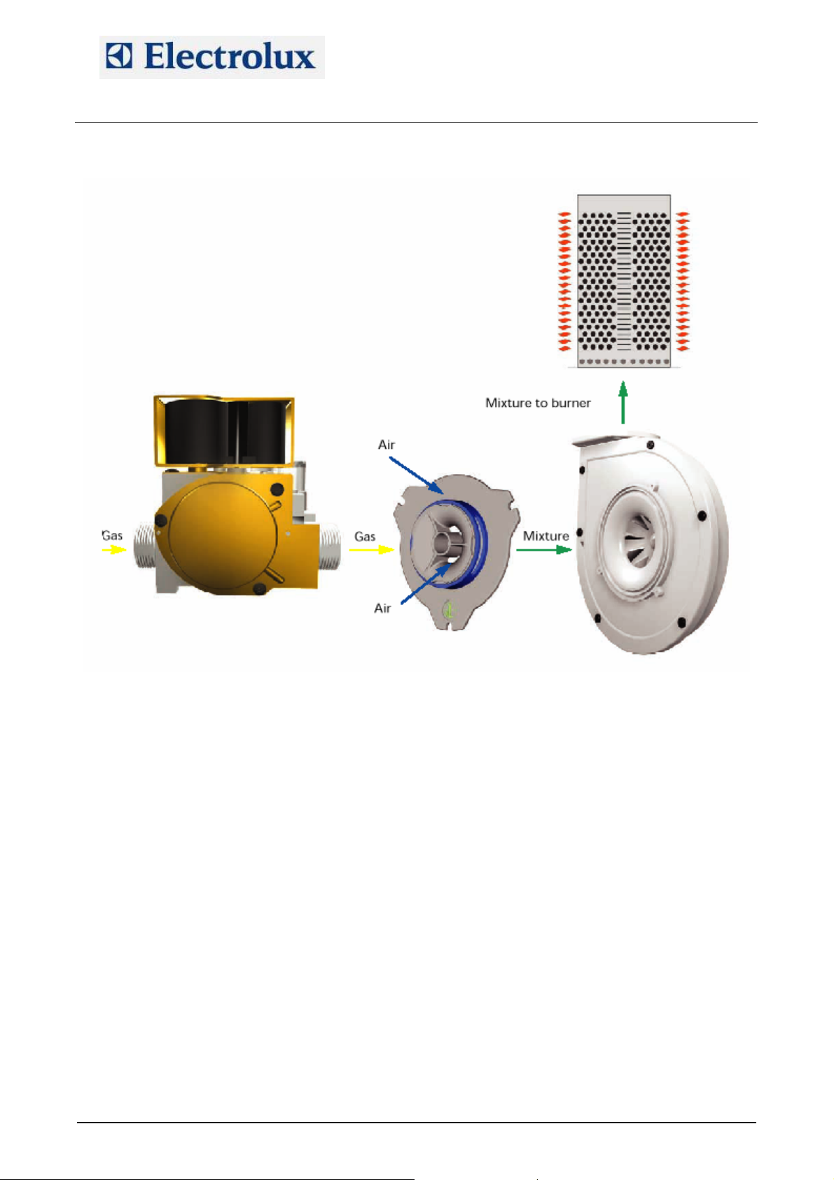
13. Gas system
The gas system is made with low emission burners. The main components are:
SIT gas valve type SIGMA 848
DC burner fan that is intaking air through a calibrated mixer where the air–gas mixture is created; then
the fun conveys the mixture to the burner
A cavity and a boiler heat exchanger made with a corrugated tube for increasing the efficiency
An ignition rod and a detection rod
An ignition device.
Starting with a cooking cycle, the POW board of the oven activates the ignition device which activates the
burner fan whose speed is controlled with a PWM signal.
The POW board activates the ignition device. From pin 8 of the ignition device a high voltage output is
carried to the digital input section of the POW board (X10/5÷8) and to the switching feeder for the burner
fans.
With an high voltage input on X10/5÷8, the POW board generates on X9/2÷5 a PWM signal to control the
speed of the burner fans, i.e. controlling the quantity of sucked gas and air. The PWM signal changes
according to the status of the burner, i.e.:
Start of the burner: controlled with parameters StcA (start of cavity burners) and Stbo (start of boiler
burners).
Full power of the burner: controlled with parameters FucA (full power of cavity burners) and Fubo (full
power of boiler burners)
Half power of the burner: controlled with parameters hAcA (half power of cavity burners) and hAbo (half
power of boiler burners)
The quantity of sucked gas is controlled with those parameters (which are determining the speed of the
burner fans), with the injector/diaphragm inserted at the outlet of the gas valve and with the calibration of the
offset value on the gas valve.
The quantity of sucked air is controlled with the above parameters and with the calibrated aerator on the
mixer.
The ignition sequence is then the following:
 Loading...