

Page 1

Service Manual
Fuller Heavy Duty Transmissions
TRSM0550
July 2010
RTLO-11610B
RTLO-11610B-T2
RTLO-12610B
RTLO-12610B-T2
RTLO-13610B
RTLO-13610B-T2
RTLO-14610B-T2
RTLO-15610B
RTLO-15610B-T2
RTLO-16610B
RTLO-16610B-T2
RTLO-17610B
RTLO-17610B-T2
RTLO-18610B
RTLO-18610B-T2
RTLO-14610A
RTLOF-11610B
RTLOF-11610B-T2
RTLOF-12610B
RTLOF-12610B-T2
RTLOF-13610B
RTLOF-13610B-T2
RTLOF-14610B
RTLOF-14610B-T2
RTLOF-15610B
RTLOF-15610B-T2
RTLOF-16610B
RTLOF-16610B -T2
RTLOF-17610B
RTLOF-17610B-T2
RTLOF-18610B
RTLO-14610B
Page 2

Precautions
Warnings and Precautions
Before starting a vehicle always be seated in the driver’s seat, place the transmission in neutral, set the parking brakes and
disengage the clutch.
Before working on a vehicle place the transmission in neutral, set the parking brakes and block the wheels.
Before towing the vehicle place the transmission in neutral, and lift the rear wheels off the ground, remove the axle shafts,
or disconnect the driveline to avoid damage to the transmission during towing.
The description and specifications contained in this service publication are current at the time of printing.
Eaton Corporation reserves the right to discontinue or modify its models and/or procedures and to change specifications at any
time without notice.
Any reference to brand name in this publication is made as an example of the types of tools and materials recommended for use
and should not be considered an endorsement. Equivalents may be used.
This symbol is used throughout this manual to call attention to procedures where carelessness or failure to follow
specific instructions may result in personal injury and/or component damage.
Departure from the instructions, choice of tools, materials and recommended parts mentioned in this publication may jeopardize
the personal safety of the service technical or vehicle operator.
Warning: Failure to follow indicated procedures creates a high risk of personal injury to servicing technician.
Caution: Failure to follow indicated procedures amy cause component damage of malfunction.
Note: Additional service information not covered in the service procedures.
Tip: Helpful removal and installation procedures to aid in the service of this unit.
Always use genuine Eaton replacement parts.
1
Page 3

Table of Contents
General Information
General Service Practices and Part Inspection ............ 1
How to use this Manual ............................................... 5
Model Designation ...................................................... 8
Power Flow ................................................................. 9
Timing Procedures .................................................... 13
Tool Reference .......................................................... 15
Preventive Maintenance
Lubrication ................................................................ 16
Preventative Maintenance ......................................... 18
Inspection ................................................................. 20
Rear Seal Maintenance .............................................. 21
External Parts
How to Disassemble the External Parts ..................... 22
How to Assemble the External Parts ......................... 23
How to Remove the Air Lines and Hose .................... 24
How to Install the Air Lines and Hose ....................... 25
How to Remove the Air Filter/Regulator .................... 26
How to Install the Air Filter/Regulator ....................... 27
How to Remove a Roadranger Valve ......................... 28
How to Install a Roadranger Valve ............................ 29
How to Remove the Range Actuator Valve ................ 30
How to Install the Range Actuator Valve ................... 31
How to Remove the Top 2 Valve Assembly ............... 33
How to Install the Top 2 Valve Assembly .................. 34
How to Remove the Gear Shift Lever ........................ 35
How to Install the Gear Shift Lever ............................ 36
How to Remove the Shift Bar Housing ...................... 37
How to Install the Shift Bar Housing ......................... 38
How to Remove the Output Yoke/Companion Flange 39
How to Install the Output Yoke/Companion Flange ...40
How to Remove the Auxiliary Section
Without Tapered Bearings ..................................... 41
How to Install the Auxiliary Section
Without Tapered Bearings ..................................... 43
How to Remove the Auxiliary Section
With Tapered Bearings .......................................... 45
How to Install the Auxiliary Section
With Tapered Bearings .......................................... 48
The Shimming Procedure For Tapered Bearings ....... 50
How to Remove the Clutch Housing .......................... 53
How to Install the Clutch Housing ............................. 54
How to Remove the Input Shaft
Without Disassembling the Transmission .............55
How to Install the Input Shaft
Without Disassembling the Transmission .............57
Shift Bar Housing
Shift Bar Housing Identification .................................59
How to Disassemble the Gear Shift Lever ..................61
How to Assemble the Gear Shift Lever ......................63
How to Disassemble the Standard Shift Bar Housing 65
How to Assemble the Standard Shift Bar Housing .....68
How to Disassemble the Standard
Shift Bar Housig (w/Super 10 on cover) ................71
How to Assemble the Standard
Shift Bar Housing (w/Super 10 on cover) ..............74
How to Disassemble the Forward
Shift Bar Housing (w/Super 10 on cover) ..............77
How to Assemble the Forward
Shift Bar Housing(w/Super 10 on cover) ...............80
How to Disassemble the New Forward
Shift Bar Housing (w/Super 10 on cover) ..............83
How to Assemble the New Forward
Shift Bar Housing (w/Super 10 on cover) ..............86
Front Section
How to Disassemble the Front Section ......................89
How to Remove the Auxiliary Drive Gear Assembly ...90
How to Remove the Reverse Idler Gear Assembly .....91
How to Remove the Countershaft Bearings ...............93
How to Remove the Mainshaft Assembly ..................95
How to Remove the Countershaft Assemblies ...........96
How to Remove the Input Shaft Assembly ................97
How to Assemble the Front Section ...........................99
How to Install the Reverse Idler Gear Assembly ......100
How to Install the Countershaft Assemblies ............102
How to Install the Countershaft Bearings .................103
How to Install the Input Shaft Assembly ..................105
How to Install the Mainshaft Assembly ....................108
How to Install the Auxiliary Drive Gear Assembly ....109
How to Disassemble the Auxiliary Drive Gear Assembly
110
How to Assemble the Auxiliary Drive Gear Assembly 112
How to Disassemble the Countershaft Assembly .....114
How to Assemble the Countershaft Assembly .........115
How to Disassemble the Mainshaft Assembly .........117
How to Assemble the Mainshaft Assembly ..............119
Page 4

Table of Contents
Auxiliary Section
How to Disassemble the Auxiliary Section .............. 124
How to Remove the Front Auxiliary Drive Gear ....... 125
How to Remove the Countershaft Assemblies
(w/Tapered Bearings) .......................................... 126
How to Remove the Countershaft Assemblies
(w/Ball Bearings) A Series ................................... 128
How to Remove the Rear Auxiliary Drive Gear ........ 130
How to Disassemble the Range Cylinder Assembly 131
How to Disassemble the Output Shaft Assembly .... 135
How to Disassemble the Splitter Cylinder Assembly 137
How to Assemble the Auxiliary Section ................... 139
How to Assemble the Output Shaft Assembly ......... 140
How to Assemble the Output Shaft Assembly
(A Series) ........................................................... 143
How to Install the Countershaft Assemblies
(w/Tapered Bearings) ......................................... 147
How to Install the Countershaft Assemblies
(w/Ball Bearings) A Series .................................. 150
How to Assemble the Range Cylinder Assembly ..... 153
How to Install the Rear Auxiliary Drive Gear ............ 157
How to Assemble the Splitter Cylinder Assembly .... 158
How to Install the Front Auxiliary Drive Gear ........... 161
How to Disassemble the Synchronizer Assembly .... 162
How to Assemble the Synchronizer Assembly ........ 163
Options
How to Remove the Integral Oil Pump .................... 165
How to Install the Integral Oil Pump ....................... 167
How to Disassemble the Integral Oil Pump ............. 169
How to Assemble the Integral Oil Pump .................. 171
Page 5

General Information
General Service Practices and Part Inspection
Disassembly
It is assumed in the detailed assembly instructions that the lubricant has been drained from the transmission, the necessary linkage and vehicle air lines disconnected and the transmission has been removed from vehicle chassis. Removal of the gear shift
lever housing assembly (or remote control assembly) is included in the detailed instructions (External Parts/Shift Bar Housing/
How to Remove the Gear Shift Lever); however, this assembly MUST be detached from the shift bar housing before transmission
can be removed.
CAUTION: Follow closely each procedure in the detailed instructions, make use of the text, illustrations, and photographs provided.
Assemblies
When disassembling the various assemblies, such as the mainshaft, countershafts, and shift bar housing, lay all parts on a clean
bench in the same sequence as removed. This procedure will simplify assembly and reduce the possibility of losing parts.
Bearings
Carefully wash and lubricate all usable bearings as removed and protectively wrap until ready for use. Remove bearings planned
to be reused with pullers designed for this purpose.
Cleanliness
Provide a clean place to work. It is important that no dirt or foreign material enters the unit during repairs. Dirt is an abrasive and
can damage bearings. It is always good practice to clean the outside of the unit before starting the planned disassembly.
Input Shaft
The input shaft can be removed from the transmission without removing the countershaft, mainshaft, or main drive gear. Special
procedures are required and provided in this manual.
Snap Rings
Remove snap rings with pliers designed for this purpose. Snap rings removed in this manner can be reused, if they are not sprung
or loose.
When using Tools to Move Parts
Always apply force to shafts, housings, etc., with restraint. Movement of some parts is restricted. Never apply force to driven parts
after they stop solidly. The use of soft hammers, soft bars, and mauls for all disassembly work is recommended.
1
Page 6

For parts or service call us
Pro Gear & Transmission, Inc.
1 (877) 776-4600
(407) 872-1901
parts@eprogear.com
906 W. Gore St.
Orlando, FL 32805
Page 7

General Information
Inspection
Before assembling the transmission, check each part carefully for abnormal or excessive wear and damage to determine reuse or
replacement. When replacement is necessary, use only genuine Eaton® Fuller® Transmission parts to assure continued performance and extended life from your unit.
Since the cost of a new part is generally a small fraction of the total cost of downtime and labor, avoid reusing a questionable part
which could lead to additional repairs and expense soon after assembly. To aid in determining the reuse or replacement of any
transmission part, consideration should also be given to the unit’s history, mileage, application, etc.
Recommended inspection procedures are provided in the following checklist.
Bearings
1. Wash all bearings in clean solvent. Check balls, rollers, and raceways for pitting, discoloration, and spalled areas. Replace
bearings that are pitted, discolored, spalled, or damaged during disassembly.
2. Lubricate bearings that are not pitted, discolored, or spalled and check for axial and radial clearances.
3. Replace bearings with excessive clearances.
4. Check bearing fit. Bearing inner races should be tight to shaft; outer races slightly tight to slightly loose in case bore. If
bearing spins freely in bore, case should be replaced.
Bearing Covers
1. Check covers for wear from thrust of adjacent bearing. Replace covers damaged from thrust of bearing outer race.
General Information
2. Check cover bores for wear. Replace those worn or oversized.
Clutch Release Parts
1. Check clutch release parts. Replace yokes worn at cam surfaces and bearing carrier worn at contact pads.
2. Check pedal shafts. Replace those worn at bushing surfaces.
Gears
1. Check gear teeth for frosting and pitting. Frosting of gear teeth faces presents no threat of transmission failure. Often in
continued operation of the unit, frosted gears “heal” and do not progress to the pitting stage. In most cases, gears with
light to moderate pitted teeth have considerable gear life remaining and can be reused, but gears in the advanced stage
of pitting should be replaced.
2. Check for gears with clutching teeth abnormally worn, tapered, or reduced in length from clashing during shifting. Replace gears found in any of these conditions.
3. Check axial clearance of gears.
Gear Shift Lever Housing Assembly
1. Check spring tension on shift lever. Replace tension spring if lever moves too freely.
2. If housing is disassembled, check gear shift lever bottom end and shift finger assembly for wear. Replace both gears if
excessively worn.
Gray Iron Parts
1. Check all gray iron parts for cracks and breaks. Replace parts found to be damaged.
2
Page 8

General Information
Oil Return Threads and Seals
1. Check oil return threads on the input shaft. If return action of threads has been destroyed, replace the input shaft.
2. Check oil seal in rear bearing cover. If sealing action of lip has been destroyed, replace seal.
O-Rings
1. Check all O-rings for cracks or distortion. Replace if worn.
Reverse Idler Gear Assemblies
1. Check for excessive wear from action of roller bearings.
Shift Bar Housing Assembly
1. Check for wear on shift yokes and blocks at pads and lever slot. Replace excessively worn parts.
2. Check yokes for correct alignment. Replace sprung yokes.
3. Check lockscrews in yoke and blocks. Tighten and rewire those found loose.
4. If housing has been disassembled, check neutral notches of shift bars for wear from interlock balls.
Sliding Clutches
1. Check all shift yokes and yoke slots in sliding clutches for extreme wear or discoloration from heat.
2. Check engaging teeth of sliding clutches for partial engagement pattern.
Splines
1. Check splines on all shafts for abnormal wear. If sliding clutch gears, companion flange, or clutch hub has worn marks
in the spline sides, replace the specific shaft affected.
Synchronizer Assembly
1. Check synchronizer for burrs, uneven and excessive wear at contact surface, and metal particles.
2. Check blocker pins for excessive wear or looseness.
3. Check synchronizer contact surfaces on the synchronizer cups for wear.
Washers
1. Check surfaces of all washers. Washer scored or reduced in thickness should be replaced.
3
Page 9

General Information
Assembly
Make sure that case interiors and housings are clean. It is important that dirt and other foreign materials are kept out of the transmission during assembly. Dirt is an abrasive and can damage polished surfaces of bearings and washers. Use certain precautions,
as listed below, during assemble.
Axial Clearances
Maintain original axial clearances of .006" to .015" for mainshaft gears.
Bearings
Use a flange-end bearing driver for bearing installation. These special drivers apply equal force to both bearing races, preventing
damage to balls/rollers and races while maintaining correct bearing alignment with bore and shaft. Avoid using a tubular or sleevetype driver, whenever possible, as force is applied to only one of the bearing races.
Capscrews
To prevent oil leakage and loosening, use Eaton/Fuller sealant #71205 on all capscrews.
Gaskets
Use new gaskets throughout the transmission as it is being rebuilt. Make sure all gaskets are installed. An omission of any gasket
can result in oil leakage or misalignment of bearing covers.
Initial Lubrication
Coat all limit washers and shaft splines with Lubriplate during assembly to prevent scoring and galling of such parts.
O-Rings
Lubricate all O-rings with silicon lubricant.
General Information
Universal Joint Companion Flange or Yoke
Pull the companion flange or yoke tightly into place with the output shaft nut, using 450-500 Lbf-ft of torque. Make sure the speedometer drive gear or a replacement spacer of the same width has been installed. Failure to pull the companion flange or yoke tightly
into place can result in damage to the mainshaft rear bearing.
IMPORTANT: See the appropriate Illustrated Parts Lists (specified by model series) to ensure that proper parts are used during
assemble of the transmission.
4
Page 10

General Information
How to use this Manual
This manual is designed to provide detailed information necessary to service and repair the Eaton® Fuller® transmissions listed
on the front.
As outlined on the first page, the manual has been divided into its main components: external parts, shift bar housing, front section, auxiliary section, and options (if applicable). Each component has its own tabbed section. Each tabbed section has its own
table of contents and procedural flow charts. The table of contents lists the procedures. The flow charts represent the order in
which the transmission should be disassembled or assembled. The procedures have two parts, disassembly or removal and reassembly or installation.
As mentioned the flow charts represent the order in which the transmission should be disassembled or assembled.
The following is an example of how to disassemble the auxiliary section, specifically the range cylinder assembly.
5
Page 11
General Information
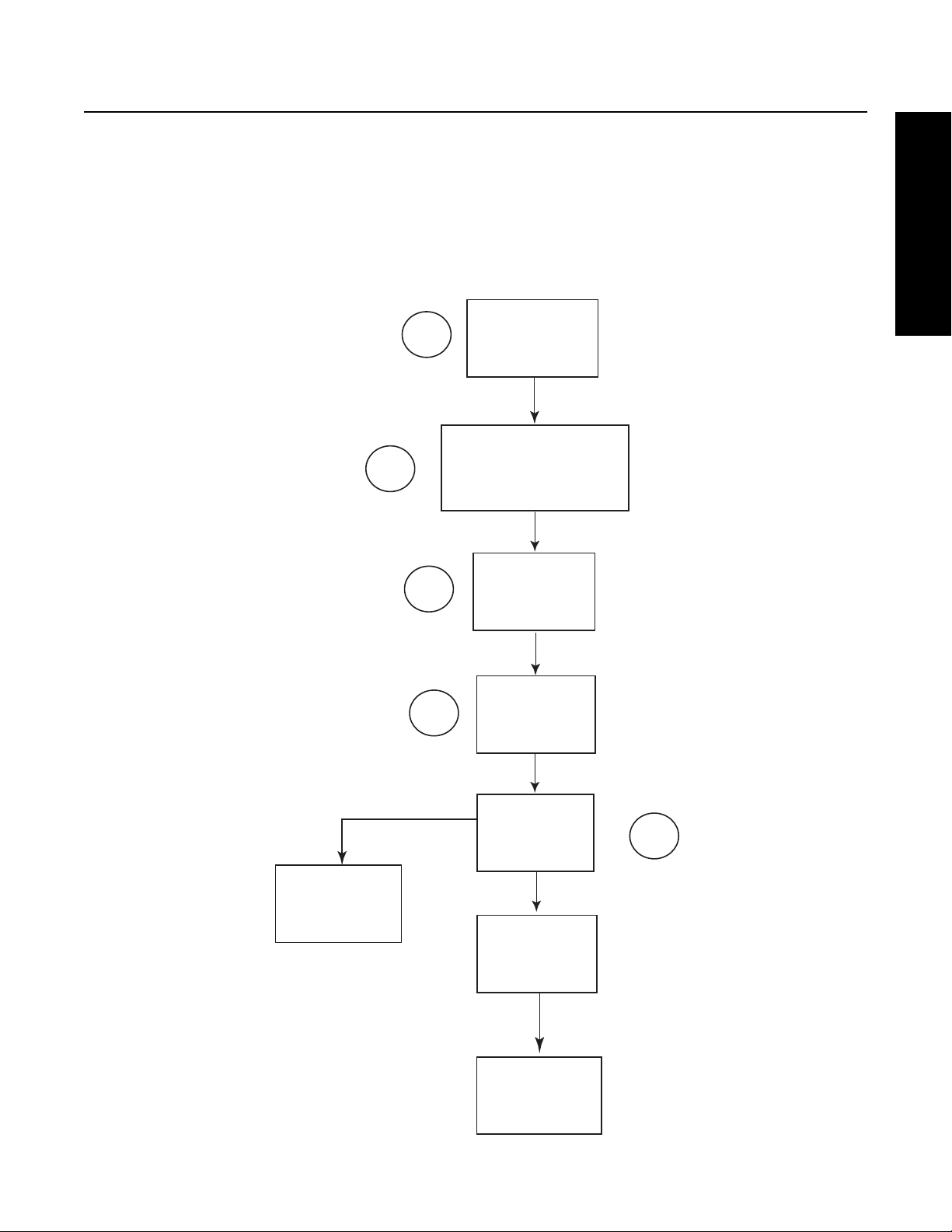
Follow the flow chart "How to Disassemble the Auxiliary Section".
1. Remove the auxiliary section from the front box.
2. Remove the front auxiliary drive gear and yoke.
3. Remove the countershaft assemblies.
4. Remove the rear auxiliary drive gear.
5. Remove the range cylinder assembly.
1
Front Auxiliary Drive
2
3
General Information
Auxiliary
Section
Gear and Yoke
Countershaft
Assemblies
Desassemble
Synchronizer
Assembly
4
Rear Auxiliary
Drive Gear
Range
Cylinder
Assembly
Output
Shaft
Assembly
Splitter
Cylinder
Assembly
5
6
Page 12

General Information
Once the range cylinder parts have been replaced, assemble the auxiliary section according to the "How to Assemble the Auxiliary
Section".
1. Assemble the output shaft assembly.
2. Assemble the synchronizer assembly, if it was disassembled.
3. Install the countershaft assemblies.
4. Install the range cylinder assembly.
Output
1
Shaft
Assembly
Assemble
Synchronizer
Assembly
2
3
4
Countershaft
Assemblies
Range
Cylinder
Assembly
Rear Auxiliary
Drive Gear
Splitter
Cylinder
Assembly
Front Auxiliary Drive
Gear and Yoke
Auxiliary
Section
7
Page 13

General Information
Model Designation
General Information and other transmission identification information are stamped on the transmission tag. To identify the transmission model designation and serial number, locate the tag on the transmission and then locate the numbers as shown.
WARNING: Do not remove or destroy the transmission identification tag.
PTO Code
Eaton Fuller
T
ransmissions
Model
RTO-14710-AS2
Eaton Corporation
Transmission Div
Kalamazoo, MI 49003
Made
In
Serial
General Information
Roadranger
Twin Countershaft
Low Inertia
Overdrive
Torque x 100
T
LO-R
14 10A6
Gear Ratio
Forward Speeds
Design Level 6 ="Multi-Mesh" Gearing
8
Page 14

General Information
Power Flow
The transmission must efficiently transfer the engine's power to the vehicle's driveline. Knowledge of what takes place in the
transmission is helpful when troubleshooting and making repairs.
1st Gear
• Power (torque) from the vehicle's engine is transferred to the transmission's input shaft.(1)
• The input shaft external splines engage the main drive gear internal splines.(2)
• Torque is split between the two countershaft drive gears.(3)
• Torque is delivered along both countershafts to the mating countershaft gears of the "engaged" mainshaft gear. The following cross section view illustrates a 1st speed gear engagement.(4)
• The external clutching teeth of the sliding clutch engage with the internal clutching teeth of the mainshaft gear which
transfers torque to the mainshaft.(5)
• The mainshaft transfers torque directly to the rear auxiliary drive gear sliding clutch which is in the rearward position.(6)
• The rear auxiliary drive gear splits torque between the two auxiliary countershaft drive gears.(7)
• Torque is delivered along both countershafts to the LO range gear in the auxiliary section.(8)
• The LO range gear delivers torque to the output shaft through the range synchronizer sliding clutch.(9)
• The output shaft delivers torque to the driveline components.(10)
9
Page 15

General Information
2nd Gear
• Power (torque) from the vehicle's engine is transferred to the transmission's input shaft.(1)
• The input shaft external splines engage the main drive gear internal splines.(2)
• Torque is split between the two countershaft drive gears.(3)
• Torque is delivered along both countershafts to the mating countershaft gears of the "engaged" mainshaft gear. The following cross section view illustrates a 2nd speed gear engagement.(4)
• The external clutching teeth of the sliding clutch engage with the internal clutching teeth of the mainshaft gear which
transfers torque to the mainshaft.(5)
General Information
• The mainshaft transfers torque directly to the auxiliary drive gear sliding clutch which is in the forward position.(6)
• The auxiliary drive gear splits torque between the two auxiliary countershaft drive gears.(7)
• Torque is delivered along both countershafts to the LO range gear in the auxiliary section.(8)
• The LO range gear delivers torque to the output shaft through the range synchronizer sliding clutch.(9)
• The output shaft delivers torque to the driveline components.(10)
10
Page 16

General Information
7th gear
• Power (torque) from the vehicle's engine is transferred to the transmission's input shaft.(1)
• The input shaft external splines engage the main drive gear internal splines.(2)
• Torque is split between the two countershaft drive gears.(3)
• Torque is delivered along both countershafts to the mating countershaft gears of the "engaged" mainshaft gear. The following cross section view illustrates a 7th speed gear engagement.(4)
• The external clutching teeth of the sliding clutch engage with the internal clutching teeth of the mainshaft gear which
transfers torque to the mainshaft.(5)
• The mainshaft transfers torque directly to the rear auxiliary drive gear sliding clutch which is in the rearward position.(6)
• Torque is delivered to the back of the rear auxiliary drive gear. The range synchronizer sliding clutch is in the forward
position, transferring torque directly to the output shaft.(7)
• The output shaft delivers torque to the driveline components.(8)
11
Page 17

General Information
8th Gear
• Power (torque) from the vehicle's engine is transferred to the transmission's input shaft.(1)
• The input shaft external splines engage the main drive gear internal splines.(2)
• Torque is split between the two countershaft drive gears.(3)
• Torque is delivered along both countershafts to the mating countershaft gears of the "engaged" mainshaft gear. The following cross section view illustrates a 8th speed gear engagement.(4)
• The external clutching teeth of the sliding clutch engage with the internal clutching teeth of the mainshaft gear which
transfers torque to the mainshaft.(5)
General Information
• The mainshaft transfers torque directly to the front auxiliary drive gear sliding clutch which is in the forward position.(6)
• The front auxiliary drive gear splits torque between the two auxiliary countershaft drive gears.(7)
• Torque is delivered along both countershafts to the rear auxiliary drive gear.(8)
• Torque is transferred to the range synchronizer sliding clutch which is in the forward position delivering torque directly
to the output shaft.(9)
• The output shaft delivers torque to the driveline components.(10)
12
Page 18

Timing
Timing Procedures
It is essential that both countershaft assemblies of the front and auxiliary sections are "timed." This assures proper tooth contact
is made between mainshaft gears seeking to center on the mainshaft during torque transfer and mating countershaft gears that
distribute the load evenly. If not properly timed, serious damage to the transmission is likely to result from unequal tooth contact
causing the mainshaft gears to climb out of equilibrium.
Timing is a simply procedure of marking the appropriate teeth of a gear set prior to installation and placing them in proper mesh
while in the transmission. In the front section, it is necessary to time only the drive gear set. And depending on the model, only
the LO range, deep reduction, or splitter gear set is timed in the auxiliary section.
Front Section
A. Marking countershaft drive teeth.
1. Prior to placing each countershaft assembly into the case, clearly mark the tooth located directly over the drive gear
keyway as shown. This tooth is stamped with an "O" to aid identification.
B. Marking main drive gear teeth.
1. Mark any two adjacent teeth on the main drive gear.
2. Mark the two adjacent teeth located directly opposite the first set marked on the main drive gear. As shown to the left,
there should be an equal number of unmarked gear teeth on each side between the marked sets.
13
Page 19

Timing
C. Meshing marked countershaft drive gear teeth with marked main drive gear teeth.
(After placing the mainshaft assembly into the case, the countershaft bearings are installed to complete installation of the countershaft assemblies.)
1. When installing the bearings on the left countershaft, mesh the countershaft drive gear marked tooth with either set of
main drive gear two marked teeth.
2. Repeat the procedure when installing the bearings on the right countershaft, make use of the remaining set of main
drive gear two marked teeth to time assembly.
Auxiliary Section
A. Timing the auxiliary countershafts.
Standard Auxiliary Section
General Information
1. Mark any two teeth on the LO range gear. Then mark two teeth located directly opposite the first marked.
2. Prior to placing each auxiliary countershaft assembly into housing, mark the tooth on each auxiliary countershaft
assembly LO range gear stamped with the "O".
3. Follow the assembly procedures in the "Auxiliary Section".
Helical Auxiliary Section
1. Mark any tooth on the LO range gear. Then mark a tooth located directly opposite the first marked.
2. Prior to placing each auxiliary countershaft assembly into housing, mark the two teeth on each auxiliary countershaft
assembly LO range gear stamped with the two "O"s. Repeat the procedure on each auxiliary countershaft reduction gear.
3. Follow the assembly procedures in the "Auxiliary Section".
14
Page 20

Tool Reference
Tool Reference
Some repair procedures pictured in this manual show the use of specialized tools. Their actual use is recommended as they
make transmission repair easier, faster, and prevent costly damage to critical parts.
But for the most part, ordinary mechanic's tools such as socket wrenches, screwdrivers, etc., and other standard shop items
such as a press, mauls and soft bars are all that is needed to successfully disassemble and reassemble any Eaton Fuller Transmission.
The specialized tools can be obtained from a tool supplier or made from tool prints as required by the individual user. Detailed
Eaton Fuller Transmission Tool Prints are available upon request by writing to:
Roadranger Literature Services
Attn: Contract 4 / CA#182
1750 Wallace Ave.
St. Charles, IL 60174-3404
Phone: 888-ETN-INFO (386-4636)
15
Page 21

Lubrication / Application Information
Lubrication
For a list of Eaton Approved Synthetic Lubricants, see TCMT-0021 or call 1-800-826-HELP (4357)
The use of lubricants not meeting these requirements will affect warranty coverage.
Additives and friction modifiers must not be introduced.
Never mix engine oils and gear oils in the same transmission.
Buy from a reputable dealer
For a list of approved and reputable dealers, write to:
Eaton Corporation
Worldwide Marketing Services
P.O.Box 4013
Kalamazoo MI 49003
Transmission Operating Angles
If the transmission operating angle is more than 12°, improper lubrication will occur. The operating angle is the transmission
mounting angle in the chassis plus the percent of upgrade (expressed in degrees).
For operating angles over 12°, the transmission must be equipped with an oil pump or cooler kit to insure proper lubrication.
Operating Temperatures with Oil Coolers
Preventive Maintenance
The transmission must not be operated consistently at temperatures above 250°F. However, intermittent operating temperatures
to 300°F do not harm the transmission. Operating temperatures above 250°F increases the lubricant’s oxidation rate and shortens
its effective life. When the average operating temperature is above 250°F, the transmission can require more frequent oil changes
or external cooling.
The following conditions in any combination can cause operating temperatures of over 250°F:
a. Operating consistently at slow speeds.
b. High ambient temperatures.
c. Restricted air flow around transmission.
d. Exhaust system too close to transmission.
e. High horsepower operation.
External oil coolers are available to reduce operating temperatures when the above conditions are encountered.
16
Page 22

Lubrication / Application Information
Oil Cooler Chart
Transmission Oil Coolers are:
Recommended
With engines of 350 H.P. and above
Required
-With engines 399 H.P. and above and GCW’s over 90,000 lbs.
-With engines 399 H.P. and above and 1400 lb.ft or greater torque.
-With engines 450 H.P and above.
17
Page 23

Preventive Maintenance
Preventative Maintenance
Everyday there are countless vehicles operating over the highways with transmissions in such a neglected mechanical condition,
they can be referred to as failures looking for a place to break down. They lack a proper and organized preventive maintenance
program.
Preventive maintenance is a general term which applies to all procedures necessary to have maximum life and satisfactory service at the lowest possible cost, short of removing and repairing the unit.
A number of conditions contrary to good preventive maintenance can generally be pointed to when inspecting a failed transmission. Taking a few minutes every so many hours or miles to do a few simple checks could help avoid eventual breakdown or
reduce the repair cost. If the transmission is not cared for, it will breakdown.
Checks Before Transmission Removal
1. Air System and Connections
Check for leaks, worn air lines, loose connections and capscrews. See SERVICING AIR SYSTEM.
2. Clutch Housing Mounting
Check all capscrews of clutch housing flange for looseness.
3. Clutch Release Bearing (Not Shown)
Remove hand hole cover and check radial and axial clearance in release bearing.
Check relative position of thrust surface of release bearing with thrust sleeve on push-type clutches.
4. Clutch Pedal Shaft and Bores
Pry upward on shafts to check wear.
If excessive movement is found, remove clutch release mechanism and check bushings on bores and wear on shafts.
See OEM literature.
5. Lubricant
Preventive Maintenance
Change at specified service intervals.
Use only the types and grades as recommended. See LUBRICANTS.
6. Filler and Drain Plugs
Remove filler plugs and check level of lubricant at specified intervals. Tighten fill and drain plugs securely.
7. Capscrews and Gaskets
Check all capscrews, especially those on PTO covers and rear bearing covers for looseness which would cause oil leakage.
Check PTO opening and rear bearing covers for oil leakage due to faulty gasket.
8. Gear Shift Lever
Check for looseness and free play in housing. If lever is loose in housing, proceed with Check No. 9.
9. Gear Shift Lever Housing Assembly
Remove air lines at slave valve and remove the gear shift lever housing assembly from the transmission.
Check the tension spring and washer for set and wear.
Check the gear shift lever spade pin and slot for wear.
18
Page 24

Preventive Maintenance
Check bottom end of gear shift lever for wear and check slot of yokes and blocks in shift bar housing for wear at contact
points with shift lever.
Checks With Drive Line Dropped
10. Universal Joint Companion Flange or Yoke Nut
Check for tightness. Tighten to recommended torque.
11. Output Shaft
Pry upward against output shaft to check radial clearance in mainshaft rear bearing.
Checks With Universal Joint Companion Flange or Yoke Removed.
NOTE:If necessary, use solvent and shop rag to clean sealing surface of companion flange or yoke. Do not use crocus
cloth, emery paper, or other abrasive materials that will mar surface finish.
12. Splines on Output Shaft
Check for wear from movement and chucking action of the universal joint companion flange or yoke.
13. Mainshaft Rear Bearing Cover
Check oil seal for wear.
19
Page 25

Preventive Maintenance
Inspection
Table 1:
Part to inspect What to Check For Action to be Done
Speedometer Connections
Rear Bearing Cover
capscrews, Gasket,
and Nylon Collar
Output Yoke Retaining Nut
PTO Covers and
Openings
Grey Iron Parts Check front bearing cover, front case, shift bar
Front Bearing Cover Check return threads for damage. Check the cap-
Speedometer cables should not be loose. Should
be an O-Ring or gasket between the mating
speedometer sleeve and the rear bearing cover.
Check retaining capscrews for tightness. Verify
nylon collar and gasket are installed at the chamfered hole, aligned near the mechanical speedometer opening. Verify that a rear bearing cover
gasket is in place.
Check the output yoke retaining nut for tightness. Torque the output yoke retaining nut to 450-500
Check the capscrews for tightness. Apply Eaton Sealant #71205 to the capscrew
housing, rear bearing cover, and clutch housing
for cracks or breaks.
screws for tightness.
Applied hydraulic thread sealant #71208 to
threads. Torque speedometer sleeve to 35-50
Lbf-ft. Replace the O-ring/gasket if damaged or
missing.
Apply Eaton Sealant #71205 to the capscrew
threads. Torque capscrews to 35-45 Lbf-ft.Use
new parts if need to replace. Apply Eaton Sealant
#71205 to the capscrew threads. Torque capscrews to 35-45 Lbf-ft. Install a new gasket if
rear bearing cover was removed.
Lbf-ft. Do not over torque nut.
threads. Tighten 6 bolt PTO capscrews to 35-45
Lbf-ft. Tighten 8 bolt PTO capscrews to 50-65
Lbf-ft.
Replace parts found to be damaged.
If threads damaged, replace the input shaft.
Tighten the capscrews to 35-45 Lbf-ft.
Preventive Maintenance
Oil Cooler and Oil Filter
Oil Drain Plug, Oil Fill
Plug
Check all connections, fittings, hoses, and filter element for tightness.
Check the oil drain plug and the oil fill plug for
leakage.
Tighten any loose fittings.
Torque the drain plug to 45-55 Lbf-ft. Torque the
oil fill plug to 60-70 Lbf-ft.
20
Page 26
Preventive Maintenance
Oil Leak Inspection Process
Inspect for Oil Leak
Determine if it is a Weep or a Leak
Weep: Stained, damp, no drips, light oil film,
dirt adhered to the contaminated area.
Gasket Rear Seal Leak
Leak: Extremely wet or dripping of oil in the
contaminated area.
Step 1
1. Clean suspected oil weep
area with a clean dry cloth
or mild soluble degreaser.
2. Ensure lube is to proper
level.
3. Notify the customer that it
is only a weep and it is not
considered to be detrimental
to the life of the transmission.
4. Repair is complete.
1. Do not repair: Rear seal is
designed to allow minimal
seepage (refer to Roadranger
TCSM-0912 Seal Maintance
Guide).
2. Ensure lube is to proper
level.
Step 2
Step 3
1. Determin
2. If origin of leak is obvious skip to Step 3.
3. If the origin of the oil leak is not obvious then
use either of the two following steps to determine
the oil leak:
Note: Do not use a high pressure spray washer to
clean the area. Use of a high pressure spray may
force contamination into the area of concern and
temporarily disrupt the leak path.
i. Clean area with a clean dry cloth or mild
soluble degreaser and fill the transmission
the proper lube level.
OR
ii. Clean the area as noted above and insert tracer
dye into the transmission lube and fill
transmission to proper lube level.
Operate vehicle to normal transmission operating
temperature and inspect the area for oil leak(s)
visually or if tracer dye was introduced use an UVL
(Ultraviolet Light) to detect the tracer dye’s point
of or
Note: When inspecting for the origin of the leak(s)
make sure the assumed leak area is not being
contaminated by a source either forward or above
the identified area such as the engine, shift tower,
shift bar housing, top mounted oil cooler, etc...
e the origin of the leak path.
to
igin.
21
Once the origin of the leak is identified, repair the
oil leak using proper repair procedures from the
designated model service manual.
Step 4
After the
repair is completed, verify the leak is
repaired and operate the vehicle to normal
transmission operating temperature.
Inspect repaired area to ensure oil leak has been
eliminated. If the leak(s) still occurs, repeat steps
or contact the Roadranger Call Center at
1-800-826-4357.
Page 27
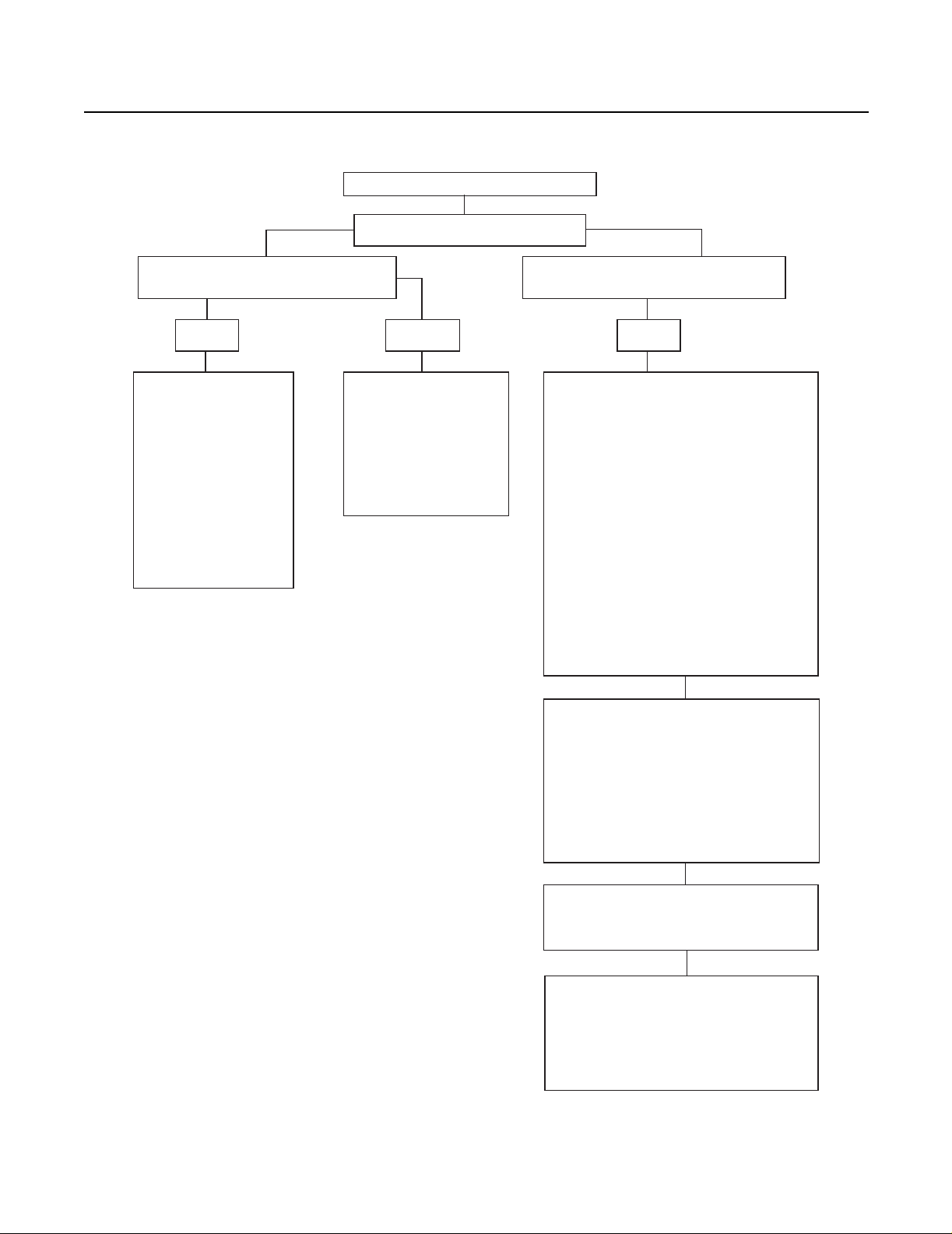
How to Disassemble the External Parts
How to Disassemble the External Parts
EXTERNAL
PARTS
AIR FILTER/
REGULATOR
AIR
SYSTEM
AIR LINES
AND HOSES
ROADRANGER
VALVE
Clutch
Housing
External Parts
CHANGING THE
INPUT SHAFT
AUXILIARY
SECTION
OUTPUT YOKE/
COMPANION
FLANGE
GEAR SHIFT
LEVER
SHIFT BAR
HOUSING
LEGEND
OPTIONAL PATH
TYPICAL PATH
22
Page 28

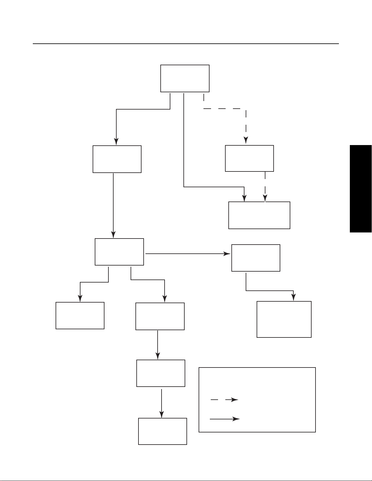
How to Assemble the External Parts
How to Assemble the External Parts
EXTERNAL
PARTS
OUTPUT YOKE/
COMPANION
FLANGE
AUXILIARY
SECTION
AIR
SYSTEM
AIR/FILTER
REGULATOR
CLUTCH
HOUSING
CHANGING THE
INPUT SHAFT
SHIFT BAR
HOUSING
GEAR SHIFT
LEVER
ROADRANGER
VALVE
23
AIR LINES
AND HOSE
LEGEND
OPTIONAL PATH
TYPICAL PATH
Page 29

Air System
How to Remove the Air Lines and Hose
Special Instructions
Before removing the air lines and hose, label or record their location.
If, after you remove the air lines and hoses, you are unsure of their location, see the Air System “Troubleshooting/Operation
Guide” TRTS-0920.
Special Tools
• Typical Service Tools
• For “push-to-connect” fittings, we recommend Eaton service tool kit K-2394. The kit contains the release tool and the
tubing cutter.
Procedure -
1. Disconnect all air lines and hose.
External Parts
2. Inspect the air lines and hose.
3. Inspect air fittings, remove if damaged.
24
Page 30

Air System
How to Install the Air Lines and Hose
Special Instructions
Make sure air lines and hose are not damaged.
Install the air lines and hose at their proper location.
All externally threaded 1/8" or 5/32" air lines and pipe fittings that are not coated with pre-applied thread sealant must be coated
with Eaton sealing material #71209 or equivalent for at least 5 complete and consecutive threads.
All externally threaded 1/4" air fittings that are not coated with pre-applied thread sealant must be coated with Eaton sealing material #71209 or equivalent for at least 3 complete and consecutive threads.
For the 1/4" I.D. air hoses, install the fixed nut end first.
To install the air lines and hose, the air filter/regulator must be in position.
If you are unsure of the air lines and hose location, see the Air System “Troubleshooting/Operation Guide” TRTS-0920.
Special Tools
• Typical Service Tools
• For ‘push-to-connect’ fittings, we recommend Eaton “Service Tool Kit” K-2394. The kit contains the release tool and a
tubing cutter.
Procedure -
1. Replace removed air fittings.
2. Connect all removed air lines and hose.
Final Check
• Make sure fittings are tight.
• Make sure air lines are not kinked.
25
Page 31

How to Remove the Air Filter/Regulator
Special Instructions
The air filter/regulator has two (2) O-rings located between the filter/regulator and the range cylinder cover.
Special Tools
• Typical Service Tools
Procedure -
1. From the air filter/regulator, remove the two (2) capscrews.
Air System
External Parts
2. From the range cylinder cover, remove the two (2) O-rings.
3. Inspect the O-rings for cracks or distortion.
26
Page 32

Air System
How to Install the Air Filter/Regulator
Special Instructions
The air filter/regulator has two (2) o-rings located between the filter/regulator and the auxiliary section.
Special Tools
• Typical Service Tools
Procedure -
1. On the range cylinder cover, position the two (2) o-rings.
2. Over the o-rings, position the air filter/regulator.
3. Apply eaton/fuller sealant #71205 or equivalent to the two
(2) retaining capscrews.
4. Install the two (2) retaining capscrews, tighten to 8-12 lb-ft
of torque.
Final Check
• Make sure the capscrews are properly torqued.
27
Page 33

How to Remove a Roadranger Valve
Special Instructions
The air lines must be depressurized.
Special Tools
• Typical Service Tools
Procedure -
1. From the Roadranger valve cover, remove the two (2)
mounting screws.
Air System
External Parts
2. Slide the Roadranger valve cover down.
3. From the air fittings, disconnect the air lines.
4. From the Roadranger base, loosen the jam nut. Rotate the
Roadranger valve until the valve is removed.
5. Inspect the parts: nut, valve cover, air lines, sheathing, and
O-rings from the lever shaft.
6. On the Roadranger valve, inspect the air fittings; remove if
damaged.
28
Page 34

Air System
How to Install a Roadranger Valve
Special Instructions
To position the Roadranger valve: the range lever must be to the front or the splitter button to the left when facing forward.
Special Tools
• Typical Service Tools
Procedure -
1. Make sure the nut, valve cover, air lines, sheathing, and Orings are in position on the lever shaft.
2. If previously removed, replace the air fittings.
3. Place the Roadranger valve on the lever shaft and rotate into
position.
4. From the Roadranger valve bottom, tighten the jam nut.
5. Connect the air lines to the air fittings.
6. Slide the cover into position on the Roadranger valve.
7. Install the Roadranger valve cover two (2) mounting screws.
Final Check
• Make sure the air lines are seated fully
29
Page 35

How to Remove the Range Actuator Valve
Special Instructions
The air lines must be depressurized.
Special Tools
• Typical Service Tools
Procedure -
1. From the mounting screws, bend the lockwasher retaining
tabs down.
2. From the range actuator valve bracket, remove the two (2)
mounting screws. The newest design of the range actuator
does not have the bracket.
Air System
External Parts
3. Remove the range actuator valve lockwasher, bracket, and
range actuator valve.
4. Inspect the air fittings, remove if damaged.
5. From the range actuator valve bore, remove the actuating
pin.
6. Inspect the actuating pin for damage, replace if necessary.
30
Page 36

Air System
How to Install the Range Actuator Valve
Special Instructions
Apply Eaton lubricant #71214 or equivalent to the O-ring so a film covers the entire surface of each O-ring.
Special Tools
• Typical Service Tools
Procedure -
1. Install the actuating pin in the range actuator valve bore.
2. If previously removed, replace the air fittings
3. Install the range actuating valve.
4. Position the range actuating valve bracket and lockwasher
over the capscrew openings. The newest design of the
range actuator does not have the bracket.
5. Apply Eaton sealant #71205 or equivalent to the retaining
capscrews.
31
Page 37

6. Install the retaining capscrews, tighten to 8-12 lb-ft of
torque.
7. Bend the retaining tabs on the lockwasher up.
Final Check
• Make sure the capscrews are properly torqued.
Air System
External Parts
32
Page 38

Air System
How to Remove the Top 2 Valve Assembly
Special Instructions
The air lines must be depressurized.
Special Tools
• Typical Service Tools
Procedure -
1. From the 3-way connector, disconnect the wire harness.
2. From the air fittings, disconnect the air lines.
3. From the Top-2 valve assembly, remove the two (2) capscrews.
33
Page 39

How to Install the Top 2 Valve Assembly
Special Instructions
The air lines must be depressurized.
Special Tools
• Typical Service Tools
Procedure -
1. Install the two (2) retaining capscrews, tighten to 35-45 lbft of torque.
Air System
External Parts
2. Connect the air lines to the air fittings.
3. Connect the 3-way connector to the harness.
34
Page 40

Shift Bar Housing
How to Remove the Gear Shift Lever
Special Instructions
The air lines must be disconnected from the transmission or from the Roadranger valve.
Remote control housings are removed the same way as gear shift levers.
Special Tools
• Typical Service Tools
Procedure -
1. From the gear shift lever base, remove the four (4) retaining
capscrews.
2. To break the gasket seal, lightly jar the gear shift housing.
3. Remove the gear shift lever housing.
4. Remove the gasket and clean all mounting surfaces of gasket material.
35
Page 41

Shift Bar Housing
How to Install the Gear Shift Lever
Special Instructions
Remote control housings are installed the same way as gear shift levers.
For standard and forward shift bar housings, make sure the two (2) balls and tension springs are in the shift bar housing top bores.
Make sure the shift block and yoke notches are aligned in the neutral position.
Special Tools
• Typical Service Tools
Procedure -
1. Position a new gear shift lever gasket on the gear shift lever
mounting surface.
2. Fit the gear shift lever into the shift block.
3. Apply Eaton/Fuller Sealant #71205 or equivalent to the retaining capscrews.
4. Install the retaining capscrews, tighten to 35-45 lb-ft of
torque.
Final Check
• Make sure the capscrews are properly torqued.
• Make sure you can shift the transmission.
External Parts
36
Page 42

Shift Bar Housing
How to Remove the Shift Bar Housing
Special Instructions
Before removing the shift bar housing, the air lines must be disconnected.
For models equipped with an oil pump and/or cooler assemblies, make sure to disconnect the lube line connected to the shift bar
housing.
There are two (2) sizes of capscrews. The 1½" capscrews are used with the lifting eyes. Note their location.
Special Tools
• Typical Service Tools
Procedure -
1. From the shift bar housing rim, remove the retaining capscrews.
2. From the alignment stud, remove the nut and washer.
3. To break the gasket seal, jar the shift bar housing.
4. Remove the shift bar housing.
5. Remove the gasket and clean all mounting surfaces of gasket material.
6. If the two (2) sets of tension springs and balls from the
housing top bores are loose, tilt the assembly and remove
them. The anti-rotating pin can be removed also. Newer shift
bar housings do not have the anti-rotating pin.
37
Page 43

How to Install the Shift Bar Housing
Special Instructions
There are two (2) sizes of capscrews. The 1½" capscrews are used with the lifting eyes.
Special Tools
• Typical Service Tools
Procedure -
1. Place the shift bars in the neutral position.
Shift Bar Housing
2. Place the mainshaft sliding clutches in the neutral position.
3. Position a new shift bar housing gasket on the shift bar
housing mounting surface.
4. As you install the shift bar housing, make sure the yokes fit
into the corresponding clutch gears slots.
5. Apply Eaton/Fuller Sealant #71205 or equivalent to the retaining capscrews.
6. Install the retaining capscrews, tighten to 35-45 lb-ft of
torque.
External Parts
7. Install the washer and nut on the alignment stud.
Final Check
• Make sure the capscrews are properly torqued.
38
Page 44

Output Yoke/Companion Flange
How to Remove the Output Yoke/Companion Flange
Special Instructions
You must remove the shift bar housing in order to lock the transmission.
For proper cleaning and maintenance, see TCSM-0912 “Seal Maintenance Guide”.
After removal of the output yoke/companion flange, temporarily replace the output shaft nut to protect the output shaft threads
during auxiliary section disassembly.
Special Tools
• Typical Service Tools
• A large breaker bar or air impact wrench
Procedure -
1. Engage two (2) mainshaft sliding clutches into two (2)
mainshaft gears to lock the transmission.
2. Use a large breaker bar or air impact wrench to remove the
output shaft nut.
3. Pull the yoke or flange straight to the rear and off the output
shaft.
39
Page 45

Output Yoke/Companion Flange
How to Install the Output Yoke/Companion Flange
Special Instructions
You must remove the shift bar housing in order to lock the transmission.
For proper cleaning and maintenance, see TCSM-0912 “Seal Maintenance Guide”.
Special Tools
• Typical Service Tools
• Torque Wrench 500 lb-ft Capacity
Procedure -
1. Engage two (2) mainshaft sliding clutches into two (2) mainshaft gears to lock the transmission.
2. Install the speedometer drive gear rotor or replacement
spacer on the output shaft inside the rear bearing cover.
3. If the slinger on the yoke is damaged, replace using a Slinger/Seal kit.
4. Slide the companion flange or yoke onto the output shaft.
External Parts
5. Install the output shaft nut, tighten to 450-500 lb-ft of
torque.
Final Check
• Make sure the output shaft nut is properly torqued.
• Unlock the transmission.
40
Page 46

Auxiliary Section
How to Remove the Auxiliary Section Without Tapered Bearings
Special Instructions
There can be different capscrew lengths, note their location.
Auxiliary sections can be removed either with the transmission in the horizontal position or the vertical position.
Special Tools
• Typical Service Tools
• An auxiliary section hanger bracket for horizontal removal
• A steel bar longer than the width of the output yoke for vertical removal
• A hoist with a lifting chain
Procedure - To remove the auxiliary section in the
horizontal position.
1. From the auxiliary section housing, remove the retaining
capscrews that attach the front section to the auxiliary section.
2. Insert the two (2) longest capscrews in the housing flange
tapped holes. Tighten evenly to move the auxiliary section
away from the front box. Go far enough to break the gasket
seal.
41
Page 47

3. Remove the capscrews from the tapped holes.
4. Attach an auxiliary section hanger bracket to the auxiliary
section top.
5. Attach a lifting chain to the auxiliary section hanger bracket.
6. Move assembly to the rear until auxiliary section is free.
7. Remove the gasket and clean all mounting surfaces of gasket material.
Procedure - To remove the auxiliary section in the
vertical position.
1. With blocks under the clutch housing to prevent input shaft
damage, place transmission in the vertical position, clutch
housing down.
2. From the auxiliary section housing, remove the retaining
capscrews that attach the front box to the auxiliary section.
Auxiliary Section
External Parts
3. Install a steel bar through the yoke.
4. Attach a lifting chain to the steel bar.
5. Lift assembly from the front section.
6. Remove the gasket and clean all mounting surfaces of gasket material.
42
Page 48

Auxiliary Section
How to Install the Auxiliary Section Without Tapered Bearings
Special Instructions
There are different capscrew lengths, install in the correct location.
Auxiliary sections can be installed either with the transmission in the horizontal position or the vertical position.
To install in the vertical position, the clutch housing must be installed.
Special Tools
• Typical Service Tools
• An auxiliary section hanger bracket for horizontal removal
• A steel bar longer than the width of the output yoke for vertical removal
• A hoist with a lifting chain
Procedure - To install the auxiliary section in the horizontal position.
1. Position a new gasket on the transmission mounting surface.
2. Attach an auxiliary section hanger bracket to the auxiliary
section top.
3. Attach a lifting chain to the auxiliary section hanger bracket.
4. Position the auxiliary section on the two (2) dowel pins.
5. Slide the auxiliary section on until the hanger bracket contacts the front case back.
6. Remove the auxiliary section hanger bracket.
7. Slide the auxiliary section the rest of the way into position.
8. Apply Eaton/Fuller Sealant #71205 or equivalent to the retaining capscrews.
9. Install the retaining capscrews, tighten to 35-45 lb-ft of
torque.
43
Page 49

Procedure - To install the auxiliary section in the vertical position.
1. With blocks under the clutch housing to prevent input shaft
damage, place the transmission in the vertical position,
clutch housing down.
2. Position a new gasket on the transmission mounting surface.
3. Install a steel bar through the yoke.
4. Attach a lifting chain to the steel bar.
5. Position the auxiliary section over the two (2) dowel pins.
6. Slide the auxiliary section down the dowels.
7. Apply Eaton/Fuller Sealant #71205 or equivalent to the retaining capscrews.
Auxiliary Section
External Parts
8. Install the retaining capscrews, tighten to 35-45 lb-ft of
torque.
9. Remove the steel bar and chain.
Final Check
• Make sure capscrews are properly torqued.
• Make sure the input shaft rotates.
44
Page 50

Auxiliary Section
How to Remove the Auxiliary Section With Tapered Bearings
Special Instructions
There can be different capscrew lengths, note their location.
Auxiliary sections can be removed either with the transmission in the horizontal position or the vertical position.
Auxiliary countershaft retaining straps may be installed to hold the countershafts in place. Auxiliary can be removed without straps,
use caution.
Special Tools
• Typical Service Tools
• An auxiliary section hanger bracket for horizontal removal
• A steel bar longer than the width of the output yoke for vertical removal
• A hoist with a lifting chain
• Auxiliary countershaft retaining straps
Procedure - To remove the auxiliary section in the
horizontal position.
1. Remove the four (4) capscrews and the auxiliary countershaft rear bearing cover, gasket, and rear bearing shim.
2. Install the auxiliary countershaft retaining straps with 2-3/8"
NC x 1" and 1-3/8" NC x 2-1/2" clean cap-screws.
WARNING: Do not use an air gun. Tighten by hand until the
capscrews are snug.
45
Page 51

3. From the auxiliary section housing, remove the retaining
capscrews that attach the front section to the auxiliary section.
4. Insert the two (2) longest capscrews in the housing flange
tapped holes. Tighten evenly to move the auxiliary section
away from the front box. Go far enough to break the gasket
seal.
5. Remove the capscrews from the tapped holes.
6. Attach an auxiliary section hanger bracket to the auxiliary
section top.
7. Attach a lifting chain to the auxiliary section hanger bracket.
Auxiliary Section
8. Move assembly to the rear until auxiliary section is free.
9. Remove the gasket and clean all mounting surfaces of gasket material.
Procedure - To remove the auxiliary section in the vertical position.
1. With blocks under the clutch housing to prevent input shaft
damage, place transmission in the vertical position, clutch
housing down.
2. Remove the four (4) capscrews and the auxiliary countershaft rear bearing cover, gasket, and rear bearing shim.
3. Install the auxiliary countershaft retaining straps with 2-3/8"
NC x 1" and 1-3/8" NC x 2-1/2" clean capscrews.
External Parts
WARNING: Do not use an air gun. Tighten by hand until the
capscrews are snug.
46
Page 52

Auxiliary Section
4. From the auxiliary section housing, remove the retaining
capscrews that attach the front box to the auxiliary section.
5. Install a steel bar through the yoke.
6. Attach a lifting chain to the steel bar.
7. Lift assembly from the front section.
8. Remove the gasket and clean all mounting surfaces of gasket material.
47
Page 53

Auxiliary Section
How to Install the Auxiliary Section With Tapered Bearings
Special Instructions
There are different capscrew lengths, install in the correct location.
Auxiliary sections can be installed either with the transmission in the horizontal position or the vertical position.
To install in the vertical position, the clutch housing must be installed.
Special Tools
• Typical Service Tools
• An auxiliary section hanger bracket for horizontal removal
• A steel bar longer than the width of the output yoke for vertical removal
• A hoist with a lifting chain
Procedure - To install the auxiliary section in the horizontal position.
External Parts
1. Position a new gasket on the transmission mounting surface.
2. Attach an auxiliary section hanger bracket to the auxiliary
section top.
3. Attach a lifting chain to the auxiliary section hanger bracket.
4. Position the auxiliary section on the two (2) dowel pins.
5. Slide the auxiliary section on until the hanger bracket contacts the front section back.
6. Remove the auxiliary section hanger bracket.
7. Slide the auxiliary section the rest of the way into position.
8. Apply Eaton/Fuller Sealant #71205 or equivalent to the retaining capscrews.
9. Install the retaining capscrews, tighten to 35-45 lb-ft of
torque.
10. To finish installation, see "The Shimming Procedure for Tapered Bearings".
48
Page 54

Auxiliary Section
Procedure - To install the auxiliary section in the vertical position.
1. With blocks under the clutch housing to prevent input shaft
damage, place the transmission in the vertical position,
clutch housing down.
2. Position a new gasket on the transmission mounting surface.
3. Install a steel bar through the yoke.
4. Attach a lifting chain to the steel bar.
5. Position the auxiliary section over the two (2) dowel pins.
6. Slide the auxiliary section down the dowels.
7. Apply Eaton/Fuller Sealant #71205 or equivalent to the retaining capscrews.
8. Install the retaining capscrews, tighten to 35-45 lb-ft of
torque.
9. Remove the steel bar and chain.
10. To finish installation, see "The Shimming Procedure for Tapered Bearings".
Final Check
• Make sure capscrews are properly torqued.
• Make sure the input shaft rotates.
49
Page 55

Auxiliary Section
The Shimming Procedure For Tapered Bearings
Special Instructions
The shimming procedure can be done in the horizontal or vertical position. The procedure is done the same.
Shims must be aligned properly or else the rear bearing cover may be damaged when final torque is applied.
Special Tools
• Typical Service Tools
Procedure -
1. Remove the countershaft straps. Make sure a 0.125 countershaft rear bearing shim is installed. Be sure the countershaft rear bearing races are seated in the bearing bores.
2. Install two (2) clean 3¦8" x 1" capscrews without washers directly across from each other in each bearing cover. Tapped
holes in auxiliary case must be free of thread adhesive.
3. Tighten the capscrews to 7 Lbf·in of torque. Do not install
the countershaft rear bearing cover gasket.
External Parts
50
Page 56

Auxiliary Section
4. Rotate the output shaft six (6) times clockwise, then six (6)
times counterclockwise to seat the countershaft rear bearings. Use a feeler gauge, as close to each capscrew location
as possible, and measure the gap between the countershaft
rear bearing cover and the auxiliary case. Record the measurements. Using the average measurement, refer to the
shimming chart to identify the proper shim.
5. Remove the countershaft rear bearing cover and gauging
shim.
6. Place the selected shim on the rear countershaft bearing
race.
7. Position a new gasket on countershaft rear bearing cover
mounting surface.
Feeler
Gauge
Average
Gap
Shim
Thickness
Table 1:
Standard
Shim Part
number
8. Position the countershaft rear bearing cover over the new
gasket.
9. Apply Eaton/Fuller Sealant #71205 or equivalent to the retaining capscrews.
10. Install the retaining capscrews, tighten to 35-45 lb-ft of
torque.
11. Repeat Steps 1-8 for the other countershaft rear bearing
cover.
Final Check
• Make sure capscrews are properly torqued.
• Make sure the input shaft rotates.
Oil Pump
Shim Part
Color Code
Number
.088-.089 .042-.043 21454 21474 Brown
.085.0875 .045-.046 21455 21475 Tan
51
Page 57

Table 1:
Auxiliary Section
Feeler
Gauge
Average
Shim
Standard
Shim Part
Thickness
number
Oil Pump
Shim Part
Number
Color Code
Gap
.082-.0845 .048-.049 21456 21476 Orange
.079-.0815 .051-.052 21457 21477 Yellow
.076-.0785 .054-.055 21458 21478 Green
.073-.0755 .057-.058 21459 21479 Light Blue
.070-.0725 .060-.061 21460 21480 Lavender
.067-.0695 .063-.064 21461 21481 White
.064-.0665 .066-.067 21684 21686 Black
.061-.0635 .069-.070 21685 21687 Silver
.058-.0605 .072-.074 21452 + 21452 21472 + 21472 Red + Red
.055-.0575 .075-.077 21452 + 21453 21472 + 21473 Red + Pink
.052-.0545 .078-.080 21452 + 21454 21472 + 21474 Red + Brown
External Parts
.049-.0515 .081-.083 21452 +21455 21472 + 21475 Red + Tan
.046-.0485 .084-.086 21452 + 21456 21472 + 21476 Red + Orange
.043-.0455 .087-.089 21452 + 21457 21472 + 21477 Red + Yellow
.040-.0425 .090-.092 21452 + 21458 21472 + 21478 Red + Green
.038-.0395 .093-.095 21452 + 21459 21472 + 21479 Red + Lt. Blue
52
Page 58

Clutch Housing
How to Remove the Clutch Housing
Special Instructions
Removal of the clutch housing is done in the horizontal position.
Special Tools
• Typical Service Tools
Procedure -
1. From inside the clutch housing, remove the nuts and washers.
2. From inside the clutch housing, remove the bolts.
3. Jar clutch housing to break gasket seal.
4. Pull the clutch housing from the studs and transmission
case.
5. Remove the gasket and clean all mounting surfaces of gasket material.
53
Page 59

How to Install the Clutch Housing
Special Instructions
Installation of the clutch housing is done in the horizontal position.
Special Tools
• Typical Service Tools
Procedure -
1. Position a new gasket on the housing mounting surface.
Clutch Housing
2. Install the clutch housing on the front box, pilot it on the six
studs and drive gear bearing cover.
3. Install the nuts with washers or lockwashers on the studs,
tighten to 35 lb-ft (47 N.m) + 90° CW rotation or 175 lb-ft
(237 N.m) of torque.
4. Install the capscrews with lockwashers, tighten to 115 lb-ft
(156 N.m) of torque.
Final Check
• Make sure the capscrews are properly torqued.
External Parts
54
Page 60

Changing The Input Shaft
How to Remove the Input Shaft Without Disassembling the Transmission
Special Instructions
Remove the transmission from the vehicle.
Special Tools
• Typical Service Tools
Procedure -
1. Remove the front bearing cover and gasket.
2. Remove the input shaft snap ring.
3. Drive the input shaft towards the transmission rear, through
the bearing as far as possible.
4. Pull the input shaft forward to expose the bearing snap ring.
5. To complete bearing removal, use pry bars.
6. From the drive gear front, remove the drive gear spacer.
55
Page 61

7. Remove the drive gear snap ring.
8. Pull the input shaft forward, out of the drive gear and transmission case.
Changing The Input Shaft
External Parts
56
Page 62

Changing The Input Shaft
How to Install the Input Shaft Without Disassembling the Transmission
Special Instructions
Check the bushing in the input shaft pocket, replace if worn.
Special Tools
• Typical Service Tools
• Input Shaft Bearing Driver
Procedure -
1. Install the new input shaft into main drive gear splines.
2. Position the input shaft just far enough into the gear to expose the drive gear I.D. snap ring groove.
3. Install the drive gear I.D. snap ring.
4. Install the drive gear spacer on the input shaft.
5. With the external snap ring to the outside, slide the drive
gear bearing on the input shaft and position into the case
bore.
57
Page 63

6. With the input shaft bearing driver, seat the bearing.
7. Install the bearing retainer snap ring.
8. Position a new gasket on the transmission mounting surface.
9. Position the front bearing cover on the input shaft, align the
oil return hole in the cover with the oil return hole on the
case.
Changing The Input Shaft
External Parts
10. Apply Eaton/Fuller sealant #71205 or equivalent to the retaining capscrews.
11. Install the retaining capscrews, tighten to 35-45 lb-ft of
torque.
Final Check
• Make sure the input shaft turns freely.
58
Page 64

Functions of a Shift Bar Housing
Shift Bar Housing Identification
Shift bar housings are a very important part of the transmission. No matter what kind of shift bar housing your transmission has,
they all provide the same functions
• Engage the transmission gearing.
• Prevents the driver from shifting into 2 gears at the same time.
• Prevents shifting into reverse without force.
• Actuates the back up lights.
• Actuates the neutral switches.
Standard Shift Bar housing
Forward Shift Bar Housing w/SUPER 10 on cover
Standard Shift Bar Housing w/SUPER 10 on cover
59
Page 65

New Forward Shift Bar Housing w/SUPER 10 on cover
Functions of a Shift Bar Housing
Shift Bar Housing
60
Page 66

Gear Shift Lever
How to Disassemble the Gear Shift Lever
Special Instructions
If total disassembly is needed, the Roadranger valve must be removed first.
Release the spring one coil at a time.
Special Tools
• Typical Service Tools
• A vise with brass jaws or wood blocks
Procedure -
1. Slide the Boot up the shift lever shaft and remove
61
2. With housing bottom facing up, secure the assembly in a
vise.
3. Use large screwdriver to twist between the spring and housing, forcing the spring from under the housing lugs.
4. From inside the housing tower, remove the tension spring,
washer, and gear shift lever.
5. In models so equipped, from the housing bore, remove the
nut and washer.
Page 67

6. From the housing tower spade pin bore, remove and inspect
the spade pin, discard if damaged.
7. From the housing tower inside groove, inspect the O-ring,
discard if damaged.
Gear Shift Lever
Shift Bar Housing
62
Page 68

Gear Shift Lever
How to Assemble the Gear Shift Lever
Special Instructions
Inspect tension spring and washer for wear.
Apply Eaton rust preventative lubricant #71212 or equivalent to the shift lever pivot ball. A rust preventative lubricant film should
cover all surfaces between and including the pivot ball.
Seat the tension spring one coil at a time.
Special Tools
• Typical Service Tools
• A vise with brass jaws or wood blocks
• Tension Spring Driver
Procedure -
1. With housing bottom facing up, secure the assembly in a
vise.
2. If the spade pin is damaged, replace and install the spade pin
in housing tower bore.
3. In models so equipped, install the nut and washer in the
housing bore.
4. If the O-ring is damaged, replace; lubricate the O-ring with
Eaton/Fuller lubricant #71206 or equivalent. Install the Oring in the housing tower inside groove.
5. Align the lever ball slot with the spade pin and position the
gear shift lever in the housing tower.
6. With dished-side up, install the washer over the ball.
63
Page 69

7. Use a tension spring driver to install the tension spring under the housing lugs.
8. Remove the assembly from the vise.
9. Install a rubber boot over the gear shift lever and against the
housing.
Final Check
• Make sure the gear shift lever can move.
Gear Shift Lever
Shift Bar Housing
64
Page 70

Shift Bar Housing
How to Disassemble the Standard Shift Bar Housing
Special Instructions
The shift bar housing must be removed from the transmission.
During disassembly, lay all parts on a clean bench in order of removal to facilitate assembly.
Shift bars not being removed must be kept in the neutral position or the interlocking parts lock the bars.
Start with the bottom shift bar.
Cut the lockwire and remove the lockscrews from each bar just before their removal.
Special Tools
• Typical Service Tools
Procedure -
1. If the two (2) sets of tension springs and balls from housing
bores and the anti-rotating pin have not been removed, place
the shift bar housing on its side to remove them.
2. With the housing rear to the right, lay the assembly on a flat
surface. If installed, remove the oil trough retaining capscrews and oil trough.
3. While removing the bottom yoke bar, remove the shift yoke.
65
Page 71

4. While removing the top yoke bar, remove the shift yoke assembly and block assembly.
5. Remove the interlock pin.
6. From the middle yoke bar, remove the jam nut, plain nut, and
washer.
Shift Bar Housing
7. Remove the range interlock bar.
8. From the middle yoke bar, remove the select interlock bar to
the right.
9. Pull the select tube to the left and remove the shift select
block.
Shift Bar Housing
66
Page 72

Shift Bar Housing
10. Remove the select tube with key to the left.
11. From the 1st & reverse shift yoke, remove the snap ring,
washer, spring, and plunger. From the 3rd speed block, remove the plug, spring, and plunger.
12. Inspect the yoke or block parts, replace the worn parts.
67
Page 73

Shift Bar Housing
How to Assemble the Standard Shift Bar Housing
Special Instructions
Inspect shift blocks and shift yokes for wear.
Apply Eaton sealant #71208 or equivalent to the shift bar housing plugs which are used to plug oil cooler provision holes. The
sealant should be applied so that at least 5 complete threads are covered.
Apply Eaton lockwire #1819 or equivalent to all shift bar housing assembly set screws in both blocks and yokes. The wire should
anchor the capscrew at least 2 complete 360° turns. The lockwire ends should be trimmed and bent out of the way of any part
interference.
Keep yoke bars in neutral while assembling.
Special Tools
• Typical Service Tools
Procedure -
1. Assemble the 1st & reverse shift yoke assembly:
Shift Bar Housing
a. Install the plunger in the 1st & reverse shift yoke bore,
plunger shank to the outside.
b. Install the spring into the bore over the plunger shank.
c. Position the washer over the plunger shank.
d. Install the snap ring.
2. Assemble the 3rd speed block assembly:
a. Install the plunger in the 3rd shift block bore, plunger
shank to the outside.
b. Install the spring into the bore over the plunger shank.
c. Install the plug and tighten to compress the spring.
d. After plug bottoms out, back the plug out 1-11/2 turns.
e. Complete the block assembly process by staking the
plug through the small hole in block.
68
Page 74

Shift Bar Housing
3. With the housing rear to the right, lay the assembly on a flat
surface.
4. Install the select tube in the middle boss with key in the key
slot.
5. As the select tube passes through the first boss, install the
shift select block.
6. From the right, install the select interlock bar.
7. Install the range interlock bar, chamfered end in, notched
side down.
8. At the middle yoke bar front end, install the washer, plain
nut, and jam nut.
69
Page 75

9. Install the interlock pin, centered between bosses.
10. While installing the top yoke bar, position the shift yoke assembly and block assembly. The block assembly aligns with
shift select block ear.
11. Install the lockscrews, tighten to 35-45 lb-ft of torque. Lockwire securely.
12. While installing the bottom yoke bar, position the shift yoke.
The block assembly aligns with shift select block ear.
13. Install the lockscrew, tighten to 35-45 lb-ft of torque. Lockwire securely.
14. Turn the shift bar housing over, and install the anti-rotating
pin and the two (2) sets of tension springs and balls.
Shift Bar Housing
Final Check
• Make sure interlocking system is working – can’t shift
into 2 gears at the same time.
• Make sure all capscrews are lockwired.
• Make sure the anti-rotating pin and the two (2) sets of
tension springs and balls are installed.
Shift Bar Housing
70
Page 76

Shift Bar Housing
How to Disassemble the Standard Shift Bar Housig (w/Super 10 on cover)
Special Instructions
The shift bar housing must be removed from the transmission.
During disassembly, lay all parts on a clean bench in order of removal to facilitate assembly.
Shift bars not being removed must be kept in the neutral position or the interlocking parts lock the bars.
Start with the bottom shift bar.
Cut the lockwire and remove the lockscrews from each bar just before their removal.
Special Tools
• Typical Service Tools
Procedure -
1. If the two (2) sets of tension springs and balls from housing
bores have not been removed, place the shift bar housing on
its side to remove them.
2. If installed, remove the oil trough retaining capscrews and
oil trough.
3. With the housing rear to the right, lay the assembly on a flat
surface.
4. While removing the bottom yoke bar, remove the shift yoke.
71
Page 77

5. While removing the top yoke bar, remove the shift yoke assembly and block assembly.
6. Remove the interlock pin.
Shift Bar Housing
7. From the middle yoke bar, drive center block roll pin out.
8. Pull the center bar to the right and remove the shift select
block.
Shift Bar Housing
72
Page 78

Shift Bar Housing
9. From the 1st & reverse shift yoke, remove the snap ring,
washer, spring, and plunger. From the 3rd speed block, remove the plug, spring, and plunger.
10. Inspect the yoke or block parts, replace the worn parts.
73
Page 79

Shift Bar Housing
How to Assemble the Standard Shift Bar Housing (w/Super 10 on cover)
Special Instructions
Inspect shift blocks and shift yokes for wear.
Apply Eaton sealant #71208 or equivalent to the shift bar housing plugs which are used to plug oil cooler provision holes. The
sealant should be applied so that at least 5 complete threads are covered.
Apply Eaton lockwire #1819 or equivalent to all shift bar housing assembly set screws in both blocks and yokes. The wire should
anchor the capscrew at least 2 complete 360° turns. The lockwire ends should be trimmed and bent out of the way of any part
interference.
Keep yoke bars in neutral while assembling.
Special Tools
• Typical Service Tools
Procedure -
1. Assemble the 1st & reverse shift yoke assembly:
Shift Bar Housing
a. Install the plunger in the 1st & reverse shift yoke bore,
plunger shank to the outside.
b. Install the spring into the bore over the plunger shank.
c. Position the washer over the plunger shank.
d. Install the snap ring.
2. Assemble the 3rd speed block assembly:
a. Install the plunger in the 3rd shift block bore, plunger
shank to the outside.
b. Install the spring into the bore over the plunger shank.
c. Install the plug and tighten to compress the spring.
d. After plug bottoms out, back the plug out 1-11/2 turns.
e. Complete the block assembly process by staking the
plug through the small hole in block.
74
Page 80

Shift Bar Housing
3. With the housing rear to the right, lay the assembly on a flat
surface.
4. Install the center rail in the middle boss.
5. As the center rail passes through the first boss, install the
shift block.
6. Drive the center block roll pin through the center bar to hold
the center block in position.
7. Install the interlock pin, centered between bosses.
8. While installing the top yoke bar, position the shift yoke assembly and block assembly. The block assembly aligns with
shift select block ear.
9. Install the lockscrews, tighten to 35-45 lb-ft of torque. Lockwire securely.
75
Page 81

10. While installing the bottom yoke bar, position the shift yoke.
The block assembly aligns with shift select block ear.
11. Install the lockscrew, tighten to 35-45 lb-ft of torque. Lockwire securely.
12. Install the oil trough and oil trough retaining capscrews.
13. Turn the shift bar housing over, and install the two (2) sets
of tension springs and balls.
Final Check
• Make sure interlocking system is working – can’t shift
into 2 gears at the same time.
• Make sure all capscrews are lockwired.
• Make sure the two (2) sets of tension springs and balls
are installed.
Shift Bar Housing
Shift Bar Housing
76
Page 82

Shift Bar Housing
How to Disassemble the Forward Shift Bar Housing (w/Super 10 on cover)
Special Instructions
The shift bar housing must be removed from the transmission.
During disassembly, lay all parts on a clean bench in order of removal to facilitate assembly.
Shift bars not being removed must be kept in the neutral position or the interlocking parts lock the bars.
Start with the bottom shift bar.
Cut the lockwire and remove the lockscrews from each bar just before their removal.
Special Tools
• Typical Service Tools
Procedure -
1. If the two (2) sets of tension springs and balls from housing
bores have not been removed, place the shift bar housing on
its side to remove them.
2. If installed, remove the oil trough retaining capscrews and
oil trough.
3. With the housing rear to the right, lay the assembly on a flat
surface.
4. While removing the bottom yoke bar, remove the shift yoke.
77
Page 83

5. While removing the top yoke bar, remove the shift yoke assembly and block assembly.
6. Remove the interlock pin.
Shift Bar Housing
7. From the middle yoke bar, drive center block roll pin out.
8. Pull the center bar to the right and remove the shift select
block.
Shift Bar Housing
78
Page 84

Shift Bar Housing
9. From the 1st & reverse shift yoke, remove the snap ring,
washer, spring, and plunger. From the 3rd speed block, remove the plug, spring, and plunger.
10. Inspect the yoke or block parts, replace the worn parts.
79
Page 85

Shift Bar Housing
How to Assemble the Forward Shift Bar Housing(w/Super 10 on cover)
Special Instructions
Inspect shift blocks and shift yokes for wear.
Apply Eaton sealant #71208 or equivalent to the shift bar housing plugs which are used to plug oil cooler provision holes. The
sealant should be applied so that at least 5 complete threads are covered.
Apply Eaton lockwire #1819 or equivalent to all shift bar housing assembly set screws in both blocks and yokes. The wire should
anchor the capscrew at least 2 complete 360° turns. The lockwire ends should be trimmed and bent out of the way of any part
interference.
Keep yoke bars in neutral while assembling.
Special Tools
• Typical Service Tools
Procedure -
1. Assemble the 1st & reverse shift yoke assembly:
Shift Bar Housing
a. Install the plunger in the 1st & reverse shift yoke bore,
plunger shank to the outside.
b. Install the spring into the bore over the plunger shank.
c. Position the washer over the plunger shank.
d. Install the snap ring.
2. Assemble the 3rd speed block assembly:
a. Install the plunger in the 3rd shift block bore, plunger
shank to the outside.
b. Install the spring into the bore over the plunger shank.
c. Install the plug and tighten to compress the spring.
d. After plug bottoms out, back the plug out 1-11/2 turns.
e. Complete the block assembly process by staking the
plug through the small hole in block.
80
Page 86

Shift Bar Housing
3. With the housing rear to the right, lay the assembly on a flat
surface.
4. Install the center rail in the middle boss.
5. As the center rail passes through the first boss, install the
shift block.
6. Drive the center block roll pin through the center bar to hold
the center block in position.
7. Install the interlock pin, centered between bosses.
8. While installing the top yoke bar, position the shift yoke assembly and block assembly. The block assembly aligns with
shift select block ear.
9. Install the lockscrews, tighten to 35-45 lb-ft of torque. Lockwire securely.
81
Page 87

10. While installing the bottom yoke bar, position the shift yoke.
The block assembly aligns with shift select block ear.
11. Install the lockscrew, tighten to 35-45 lb-ft of torque. Lockwire securely.
12. Install the oil trough and oil trough retaining capscrews.
13. Turn the shift bar housing over, and install the two (2) sets
of tension springs and balls.
Final Check
• Make sure interlocking system is working – can’t shift
into 2 gears at the same time.
• Make sure all capscrews are lockwired.
• Make sure the two (2) sets of tension springs and balls
are installed.
Shift Bar Housing
Shift Bar Housing
82
Page 88

Shift Bar Housing
How to Disassemble the New Forward Shift Bar Housing (w/Super 10 on cover)
Special Instructions
The shift bar housing must be removed from the transmission.
During disassembly, lay all parts on a clean bench in order of removal to facilitate assembly.
Shift bars not being removed must be kept in the neutral position or the interlocking parts lock the bars.
Start with the bottom shift bar.
Cut the lockwire and remove the lockscrews from each bar just before their removal.
Special Tools
• Typical Service Tools
Procedure -
1. If the two (2) sets of tension springs and balls from housing
bores have not been removed, place the shift bar housing on
its side to remove them. Check the condition of the alignment pin, replace if necessary.
2. If installed, remove the oil trough retaining capscrews and
oil trough.
3. With the housing rear to the right, lay the assembly on a flat
surface.
4. While removing the bottom yoke bar, remove the shift yoke.
83
Page 89

5. While removing the top yoke bar, remove the shift yoke assembly and block assembly.
6. Remove the interlock pin.
Shift Bar Housing
7. From the middle yoke bar, drive center block roll pin out.
8. Pull the center bar to the right and remove the shift select
block.
Shift Bar Housing
84
Page 90

Shift Bar Housing
9. From the 1st & reverse shift yoke, remove the snap ring,
washer, spring, and plunger. From the 3rd speed block, remove the plug, spring, and plunger.
10. Inspect the yoke or block parts, replace the worn parts.
85
Page 91

Shift Bar Housing
How to Assemble the New Forward Shift Bar Housing (w/Super 10 on cover)
Special Instructions
Inspect shift blocks and shift yokes for wear.
Apply Eaton sealant #71208 or equivalent to the shift bar housing plugs which are used to plug oil cooler provision holes. The
sealant should be applied so that at least 5 complete threads are covered.
Apply Eaton lockwire #1819 or equivalent to all shift bar housing assembly set screws in both blocks and yokes. The wire should
anchor the capscrew at least 2 complete 360° turns. The lockwire ends should be trimmed and bent out of the way of any part
interference.
Keep yoke bars in neutral while assembling.
Special Tools
• Typical Service Tools
Procedure -
1. Assemble the 1st & reverse shift yoke assembly:
Shift Bar Housing
a. Install the plunger in the 1st & reverse shift yoke bore,
plunger shank to the outside.
b. Install the spring into the bore over the plunger shank.
c. Position the washer over the plunger shank.
d. Install the snap ring.
2. Assemble the 3rd speed block assembly:
a. Install the plunger in the 3rd shift block bore, plunger
shank to the outside.
b. Install the spring into the bore over the plunger shank.
c. Install the plug and tighten to compress the spring.
d. After plug bottoms out, back the plug out 1-11/2 turns.
e. Complete the block assembly process by staking the
plug through the small hole in block.
86
Page 92

Shift Bar Housing
3. With the housing rear to the right, lay the assembly on a flat
surface.
4. Install the center rail in the middle boss.
5. As the center rail passes through the first boss, install the
shift block.
6. Drive the center block roll pin through the center bar to hold
the center block in position.
7. Install the interlock pin, centered between bosses.
8. While installing the top yoke bar, position the shift yoke assembly and block assembly. The block assembly aligns with
shift select block ear.
9. Install the lockscrews, tighten to 35-45 lb-ft of torque. Lockwire securely.
87
Page 93

10. While installing the bottom yoke bar, position the shift yoke.
The block assembly aligns with shift select block ear.
11. Install the lockscrew, tighten to 35-45 lb-ft of torque. Lockwire securely.
12. Install the oil trough and oil trough retaining capscrews.
13. Turn the shift bar housing over, and install the two (2) sets
of tension springs and balls.
Final Check
• Make sure interlocking system is working – can’t shift
into 2 gears at the same time.
• Make sure all capscrews are lockwired.
• Make sure the two (2) sets of tension springs and balls
are installed.
Shift Bar Housing
Shift Bar Housing
88
Page 94

Front Section
How to Disassemble the Front Section
FOLLOW THE SOLID LINE,
THEN THE DOTTED LINE,
THEN THE DASHED LINE
REMOVE
EXTERNAL
PARTS
DISASSEMBLE
AUXILIARY
DRIVE GEAR
REMOVE
COUNTERSHAFT
BEARINGS
AUXILIARY
DRIVE GEAR
ASSEMBLY
REVERSE
IDLER GEAR
ASSEMBLY
UPPER COUNTERSHAFT
BEARINGS
MAINSHAFT
ASSEMBLY
MOVE
REVERSE
GEAR
UPPER REVERSE IDLER GEAR
DISASSEMBLE
MAINSHAFT
DISASSEMBLE
COUNTERSHAFT
UPPER
COUNTERSHAFT
LOWER COUNTERSHAFT BEARINGS
LOWER COUNTERSHAFT
89
COUNTERSHAFT
ASSEMBLY
INPUT SHAFT
ASSEMBLY
LOWER REVERSSE IDLER GEAR
Page 95

How to Disassemble the Front Section
How to Remove the Auxiliary Drive Gear Assembly
Special Instructions
Before removing the auxiliary drive gear, the auxiliary section must be removed.
Special Tools
• Typical Service Tools
• Large pair of snap ring pliers
Procedure -
1. Remove the auxiliary bearing retainer ring capscrews.
2. Remove the mainshaft rear groove snap ring.
3. From inside the auxiliary drive gear assembly, remove the
splined washer.
4. Insert three (3) of the capscrews in the specially tapped
holes of the retainer ring.
5. Tighten the capscrews evenly to force the auxiliary drive
gear assembly from the case.
6. Remove the auxiliary drive gear from the mainshaft.
7. From the mainshaft, remove the splined washer.
Front Section
90
Page 96

How to Disassemble the Front Section
How to Remove the Reverse Idler Gear Assembly
Special Instructions
The following instructions are used to remove upper and lower reverse idler gears.
Before the upper reverse idler gear assembly can be removed, mainshaft reverse gear must be positioned forward against the
next gear.
While removing the reverse idler shaft, the thrust washer can drop to the transmission case bottom.
The mainshaft reverse gear must be moved in order to remove the upper reverse idler gear, see “How to Remove the Mainshaft
Assembly”, steps 1-3.
Special Tools
• Typical Service Tools
• Jaw Pullers or Impact Puller
Procedure -
1. From the reverse idler gear bore, use inside jaw pullers or an
impact puller to remove the auxiliary countershaft front
bearing.
2. From the idler shaft, remove the loosened lock nut and
washer.
91
Page 97

How to Disassemble the Front Section
3. From the idler shaft rear, remove the pipe plug.
4. Install an impact puller, 1¦2"-13 threaded end, and remove
the shaft from case bore.
5. As the idler shaft and idler plate are removed, remove the
thrust washer and gear.
6. Inspect the reverse gear assembly, remove the inner race
and needle bearing, if damaged.
Front Section
92
Page 98

How to Disassemble the Front Section
How to Remove the Countershaft Bearings
Special Instructions
The following instructions are used to remove the upper and lower countershaft bearings. To remove the mainshaft assembly,
only the upper countershaft bearings need to be removed.
Performing the following instructions will damage the bearings and should be not be done unless bearing replacement is planned.
The bearing inner race remains pressed on the countershaft after removal of the front bearings.
Special Tools
• Typical Service Tools
• Soft bar and a maul
• Bearing puller or pry bars
Procedure -
1. To keep the mainshaft pilot from falling out of the input shaft
pocket, temporarily install the auxiliary drive gear on the
mainshaft.
2. From each countershaft rear groove, remove the snap ring.
3. From inside the case, use a soft bar and maul to drive the
countershaft rear bearings from the case bores.
93
Page 99

How to Disassemble the Front Section
4. From the front of each countershaft, remove the capscrew
and front retainer plate.
5. Use the soft bar and maul to drive each countershaft to the
rear as far as possible. This partially unseats the front bearings.
6. Return to the case rear, and drive each countershaft forward
as far as possible. This exposes the bearing snap rings.
7. Use a bearing puller or pry bars to remove the countershaft
front bearings. If a bearing puller is used, the front bearing
cover has to be removed.
Front Section
94
Page 100

How to Disassemble the Front Section
How to Remove the Mainshaft Assembly
Special Instructions
Be careful when removing the mainshaft assembly, the sliding clutch on the end can slip off the mainshaft.
Reverse gear is also free and can fall off the shaft.
Special Tools
• Typical Service Tools
• Large hook or 3 foot piece of rope
Procedure -
1. From the mainshaft, remove the reverse gear retaining snap
ring.
2. Move the mainshaft reverse gear as far to the rear as possible and remove reverse gear I.D. snap ring.
3. Move the reverse gear forward and against the next gear, engaging the mainshaft sliding clutch spline.
WARNING: If not removing the upper reverse idler gear assembly, you must remove the upper reverse idler gear assembly shaft and roll the gear to the outside, see “How to
Remove the Reverse Idler Gear Assembly”, steps 1-4.
4. Use a large screwdriver and block the upper countershaft assembly against the case wall.
WARNING: If removing the upper reverse idler gear assembly, see “How to Remove the Reverse Idler Gear Assembly”
at this time.
5. Position the hook or rope around the mainshaft.
6. Pull the mainshaft to the rear to free the pilot from the input
shaft pocket.
7. Tilt mainshaft front up and lift assembly from the case.
95
 Loading...