


Troubleshooting Guide
Fuller Heavy-Duty Transmissions
TRTS0011 EN-US
October 2007
RTLO-11118A-MT
RTLO-9118A-MT

For parts or service call us
Pro Gear & Transmission, Inc.
1 (877) 776-4600
(407) 872-1901
parts@eprogear.com
906 W. Gore St.
Orlando, FL 32805


Introduction
WARNING................................................................................................................2
Complaint Isolation, Verification & Remedy Procedure.............................................3
How to Use this Troubleshooting Guide...................................................................4
Complaint Diagnosis
Fault Code Diagnosis..............................................................................................6
Symptom Driven Diagnosis.....................................................................................7
Pre-Test
Transmission Electrical Test....................................................................................8
Performance Evaluation
Performance Evaluation Test.................................................................................10
Testing Procedures
Power Relay Coil Test..............................................................................................12
System Voltage Test................................................................................................13
Inertia Brake Solenoid Coil Test...............................................................................15
Inertia Brake Test....................................................................................................17
Inertia Brake Switch Test.........................................................................................18
Inertia Brake Air Supply Test...................................................................................19
Transmission Converter Open Lamp Test................................................................20
Engine Speed Sensor Test......................................................................................21
Bypass/Lockup Solenoid Coil Test..........................................................................23
Interrupt Clutch Solenoid Coil Test..........................................................................25
Hydraulic System Test............................................................................................27
Input Shaft Speed Sensor Test...............................................................................29
Output Shaft Speed Sensor Test.............................................................................31
Table of Contents
Appendix I
System Overview....................................................................................................33
Electrical Schematic................................................................................................34
Wiring Diagram (fold-out page)
1

Introduction
• Before starting a vehicle always be seated in the driver’s seat,
move the shift lever to neutral, and set the parking brakes.
• If engine cranks in any other gear than neutral, service your vehicle neutral safety start circuit and start enable relay circuit immediately.
• Before working on a vehicle or leaving the cab with engine running, place the transmission in neutral, set the parking brakes,
AND block the wheels.
• Do not release the parking brake or attempt to select a gear until
the air pressure is at the correct level.
• For safety reasons, always engage the service brakes when moving the shift lever from neutral to one of the other gear positions.
• When parking the vehicle or leaving the cab, always place the shift
lever in neutral and set the parking brakes.
• TOWING: To avoid damage to the transmission during towing,
place the transmission in neutral and lift the drive wheels off the
ground or disconnect the driveline.
Every effort has been made to ensure the accuracy of all information in this manual. However, Eaton
Transmission Division makes no expressed or implied warranty or representation based on the
enclosed information. Any errors or omissions may be reported to Training and Publications, Eaton
Transmission Division, P.O. Box 4013, Kalamazoo, MI 49003
2

Complaint Isolation, Verification & Remedy Procedure
Complaint
Identify System Error via Fault Codes
Using: Service Transmission Light
Service Transmission LIght
Able to Identify Fault Codes Observe and Record
Symptoms
Introduction
Utilize Trouble Shooting Guide
Fault Code Diagnosis
Isolate System or Component Failure
Follow Trouble Shooting Guide Test Sequences
PASS
Follow Trouble Shooting Guide
Remedy Sequence Instructions
Next Step in Trouble Shooting Guide
as Required for Further Diagnosis or Repair
Utilize Trouble Shooting guide
Symptom Driven Diagnosis
FAIL
Proceed to
Re-Test
3

Introduction
For all questions
concerning
inspection,
removal,
replacement,
or adjustment
procedures,
refer to Eaton or
OEM Service and
Parts Literature.
How To Use this Troubleshooting Guide
The purpose of this manual is to assist in the diagnosis and verification of your
electronically managed heavy-duty transmission system. It should be used in
conjunction with Eaton Driver Instructions, Illustrated Parts List, Installation
Guide, and Service Manual -- as well as OEM service related material.
This guide provides three functions:
1. Service Transmission Light Diagnostics: designed to lead the service techni-
cian to the source of a problem through flashing error codes.
2. Performance Evaluation: designed to lead the service technician to the source
of a problem through a performance evaluation.
3. Test and remedy Sequences: detailed component testing designed to isolate
and resolve system failures.
Service Transmission Light Diagnostics
The Service Transmission indicator light, which is also the torque converter
open lamp, assists the mechanic in problem diagnosis via flashing signals equal
to Fault Code numbers as listed in the Fault Codes Diagnosis section of this
manual.
If a driver reports a degraded mode of operation, advise that the capabilities of
the truck should be assessed and then taken to a service site. The transmission
temperature should be monitored during the trip to the service site.
Examples of potential problem conditions under which a vehicle with a Converter Enhanced Mechanical Transmission can be driven include:
• Transmission fails to lock torque converter, but vehicle can still proceed although
speed and/or power is limited.
• Transmission is not able to select all ratios and limits the gears available.
1. Using the Service Transmission Light for Diagnostics: To activate the retrieval
of fault codes via the Service Transmission light perform the following steps:
• Active Codes: Place the Shift Lever in Neutral. Set the parking brakes. Begin
with the key in the off position. Turn the key off and back on two (2) times within
5 seconds (OFF/ON/OFF/ON). It is OK if the engine stops, or continues running,
however do not re-energize the starter when retrieving Fault Codes as you may
cause codes to clear.
• If there are no active fault codes, then retrieve the intermittent codes.
• Intermittent codes: Follow instructions for Active Codes, but turn key OFF and
ON four (4) times.
• To clear fault codes: Follow instructions for Active Codes, but turn key OFF and
ON six (6) times. Fault codes should be cleared each time the transmission is
serviced.
4

1a. After activating the retrieval of codes, to read transmission errors via the Service Transmission
light, observe the sequence of flashes exhibited by the light. The Service Transmission light will
flash in coded sequences equal to Fault Codes identified in this manual. A long pause (5 seconds) follows each code before it is repeated, or the next codes sequence is given.
Examples:
• Flash / Pause / Flash = Fault Code 11 System Controller
• Flash - Flash / Pause / Flash - Flash - Flash = Fault Code 23 Engine Speed Sensor
• Flash / Pause / Flash - Long Pause - Flash - Flash / Pause / Flash - Flash - Flash = Fault Codes 11
& 23.
1b. To identify fault codes and applicable tests signalled by the Service Transmission light refer to
the Fault code Diagnosis section of this manual.
Symptom Diagnosis
1. Refer to the Performance Evaluation test in this manual.
2. Locate and perform appropriate Test Sequence as indicated by the Performance Evaluation Test.
Before Beginning Diagnostic Procedures
It is possible to “clear” or “reset” the Converter Enhanced Mechanical Electronic Control Unit
(ECU) for some transmission errors. If the transmission is not functioning properly try these
steps before beginning diagnostic procedures:
1. Stop the vehicle.
2. Place the shift lever in neutral.
3. Set the parking brakes.
4. Turn off the engine/ignition and wait for one minute.
5. Restart the engine.
6. Resume operation.
Introduction
For all questions
concerning
inspection,
removal,
replacement,
or adjustment
procedures,
refer to Eaton or
OEM Service and
Parts Literature.
Test Sequence and Remedy Sequence
1. Locate the correct Test Sequence.
2. Always perform pre-test procedures found at the top of each Test Sequence page before begin-
ning test procedure.
3. Follow test steps in sequence.
4. Go to Remedy Sequence when required.
5. Perform appropriate removal, replacement or adjustment procedures.
5

Fault
Code
Diagnosis
For all questions
concerning
inspection,
removal,
replacement,
or adjustment
procedures,
refer to Eaton or
OEM Service and
Parts Literature.
Fault
Code
Test Procedure Page
13 Power Relay Coil Test 12
15 Inertial Brake Solenoid Coil Test 15
22 Bypass/Lockup Solenoid Coil Test 23
23 Engine Speed Sensor Test 21
33 System Voltage Test 13
56 Input Shaft Speed Sensor Test 29
57 Output Shaft Speed Sensor Test 31
6

Symptom
If no fault codes exist perform the Performance Evaluation Test. Locate and perform appropriate
test sequence as indicated by the evaluation.
Driven
Diagnosis
For all questions
concerning
inspection,
removal,
replacement,
or adjustment
procedures,
refer to Eaton or
OEM Service and
Parts Literature.
7

Transmission
Electrical
For all questions
concerning
inspection,
removal,
replacement,
or adjustment
procedures,
refer to Eaton or
OEM Service and
Parts Literature.
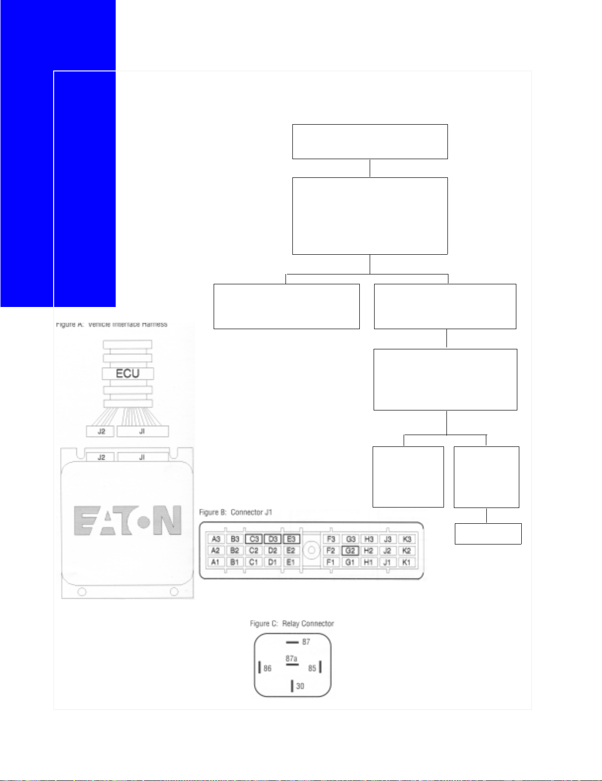
Test
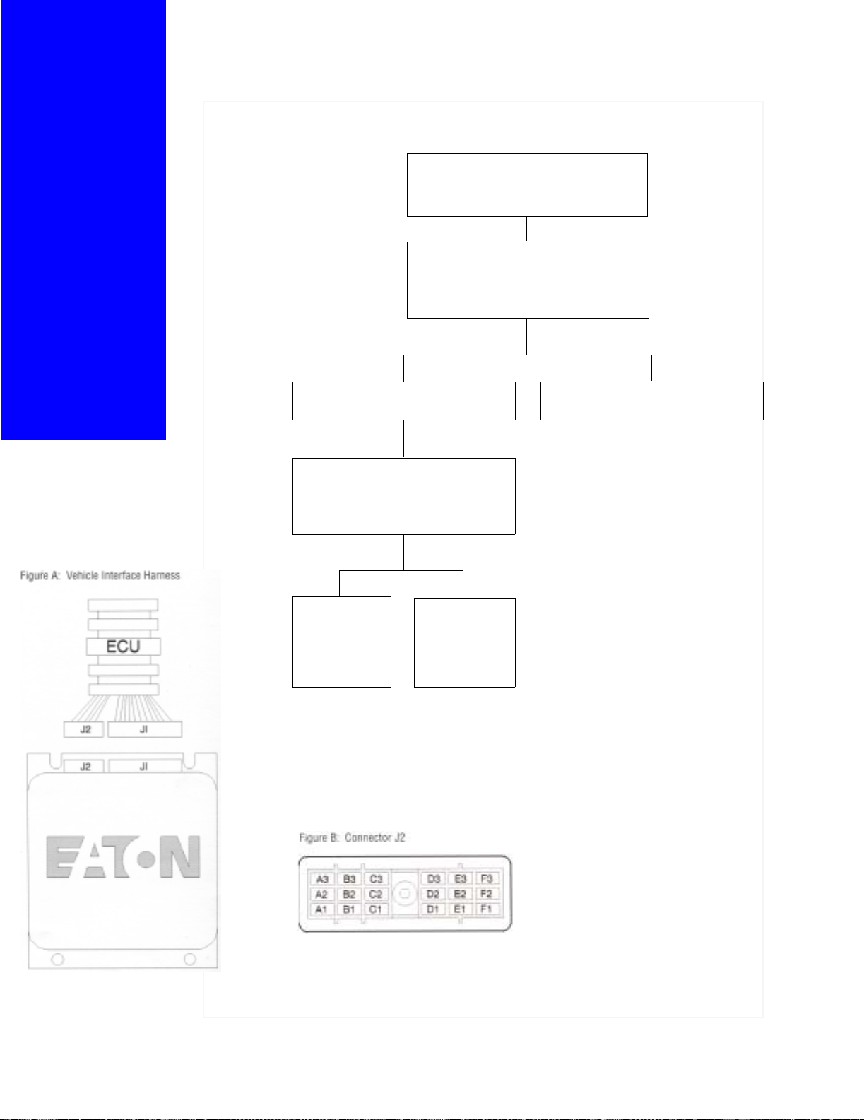
Measure voltage across vehicle battery
terminals [voltage = 12.6 volts].
Is voltage correct?
YES
Refer to Figure A below. Disconnect
vehicle interface harness connector J1
from ECU.
Refer to Figure B below. Measure resistance between pins A3, B3, C3, and battery negative terminal [resistance = 0.0-
0.4 ohms].
Is resistance correct?
YES NO
Refer to Figure B on
page 9.
Measure voltage
between harness
connector pins A3
and G2 [voltage =
battery voltage].
Is voltage correct?
A problem exists
with transmission electrical
grounds.
Contact OEM for
service information.
NO
Repair low voltage problem. Contact OEM
for service information.
YES
Refer to Figure B
below. Measure
voltage between
harness connector
pins A3 and G1
[voltage = 0 volts.]
Is voltage correct?
YES NO
CONTINUE
NO
A problem exists
in vehicle interface harness or
batter supply circuit breaker. Contact service
information.
A problem exists
in vehicle interface
harness or ignition
voltage supply circuit breaker. Contact OEM for
service information.
8

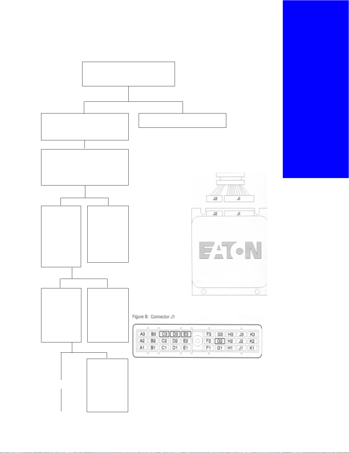
Continuation
Turn the ignition key “ON”.
Refer to Figure B on page 12.
Measure the voltage between
the harness connector pins A3
and G1 [voltage = battery voltage]. Is voltage correct?
YES NO
Turn ignition key “OFF”. A problem exists in vehicle interface har-
ness or ignition voltage supply circuit
breaker. Contact OEM for service information.
Transmission
Electrical
Test
For all questions
concerning
inspection,
removal,
replacement,
or adjustment
procedures,
refer to Eaton or
OEM Service and
Parts Literature.
Refer to Figure B below. Place
jumper wire across vehicle
interface harness connector
pins F1 and A3.
Refer to Figure B below. Measure voltage between harness
connector pins B3 and E1 [voltage = battery voltage]. Is volt-
age correct?
YES
Refer to Figure A on page 8.
Disconnect vehicle interface
harness J2 connector from
ECU.
Refer to Figure C on page 12. Measure
voltage between J1 connector pin B3
and J2 connector pin A3 [voltage = battery voltage]. Is voltage correct?
YES
NO
A problem exists in transmission power relay or vehicle
interface harness. contact
OEM for service information.
NO
Test complete
Repair/replace vehicle interface harness according to OEM service
information.
9

Performance
Evaluation
For all questions
concerning
inspection,
removal,
replacement,
or adjustment
procedures,
refer to Eaton or
OEM Service and
Parts Literature.
Test
Before beginning test procedure:
1. Set parking brakes.
2. Perform Transmission Electrical Test.
3. Turn ignition key “OFF”.
Turn ignition key “ON”.
Does converter open lamp turn “ON”?
YES
Perform fault code retrieval as outlined
in the introduction section of this manual. Are fault codes present?
YES
Perform
diagnostics for
fault codes as
outlined in the
fault code diagnostic section of
this manual.
NO
Start the vehicle
and allow the air
system to reach
governor cut off
[90-120 psi].
NO
Perform Transmission Electrical Test,
then torque Converter Open Lamp Test.
Continue
Allow the transmission temperature to
reach operating temperature [180-
°F].
220
Fully depress the clutch pedal and place
the shift lever in gear. Does the trans-
mission engage gears without harsh
grinding?
YES
Does the vehicle
move?
NO
Perform Inertia
Break Test.
YES NO
Perform the Interrupt Clutch Solenoid Test and the
Hydraulic System
Test.
10

t
Continuation
Performance
Evaluation Tes
Drive the vehicle and increase engine
rpm to 1600 rpm. Does the torque con-
verter open lamp turn “OFF”?
YES
Perform range
shift. Does range
shift complete
properly?
YES
Perform splitter
shift. Does the
splitter shift complete properly?
YES
NO
Perform Hydraulic System Test.
NO
Perform range system evaluation
according to Eaton
Fuller Air System
Troubleshooting
and Operation
Guide.
NO
For all questions
concerning
inspection,
removal,
replacement,
or adjustment
procedures,
refer to Eaton or
OEM Service and
Parts Literature.
Does engine flare
after clutch pedal
release?
YES
Perform Hydraulic
System Test.
Perform Hydraulic
System Test
Perform splitter
system evaluation
according to Eaton
Fuller Air System
Troubleshooting
and Operation
Guide.
NO
Does vehicle have
trouble pul ling
light loads?
YES NO
Test complete
11
Power
Relay
Coil
Test
For all questions
concerning
inspection,
removal,
replacement,
or adjustment
procedures,
refer to Eaton or
OEM Service and
Parts Literature.
Before beginning test procedure:
1. Set parking brakes.
2. Perform Transmission Electrical Test.
3. Turn ignition key “OFF”.
Refer to Figure A below. Disconnect
vehicle interface harness J1 connector
from the transmission ECU.
Refer to Figure B below. Measure resistance between J1 connector pins F1 and
G2 [resistance = 40-90 ohms]. Measure voltage between G2 and vehicle
ground, F1 and vehicle electrical ground
[should = battery voltage].
YES
Replace transmission ECU. Locate power relay assembly and
NO
disconnect vehicle interface harness
from relay assembly.
Refer to Figure C below. Measure
resistance between pins 85 and 86 of
each power relay [resistance = 40-90
ohms]. Is resistance correct?
YES
Replace vehicle
interface harness
according to OEM
service information.
NO
Replace power
relay assembly
according to
OEM service
information.
Test complete
12
Before beginning test procedure:
1. Set parking brakes.
2. Perform Transmission Electrical Test.
3. Turn ignition key “OFF”.
System
Voltage
Measure voltage across vehicle battery
terminals [voltage = 12.6 volts].
Is voltage correct?
YES NO
Refer to Figure A below. Disconnect
vehicle interface harness connector J1
from ECU.
Refer to Figure B below. Measure
resistance between pins A3, B3, C3,
and battery negative terminal [resistance = 0.0-0.4 ohms].
Is resistance correct?
YES NO
Refer to Figure B
below. Measure
voltage between
harness connector pins A3 and
G2 [voltage =
battery voltage].
Is voltage correct?
YES NO
A problem exists
with transmission electrical
grounds.
Contact OEM for
service information.
Repair low voltage problem. Contact
OEM for service information.
Test
For all questions
concerning
inspection,
removal,
replacement,
or adjustment
procedures,
refer to Eaton or
OEM Service and
Parts Literature.
Refer to Figure B
below. Measure
voltage between
harness connector pins A3 and
G1 [voltage = 0
volts]. Is voltage
correct?
YES NO
Continue
A problem exists
in vehicle interface harness or
battery supply circuit breaker. Contact OEM for
service information.
A problem exists
in vehicle interface harness or
ignition voltage
supply circuit
breaker. Contact
OEM for service
information.
13
System
Voltage
Test
For all questions
concerning
inspection,
removal,
replacement,
or adjustment
procedures,
refer to Eaton or
OEM Service and
Parts Literature.
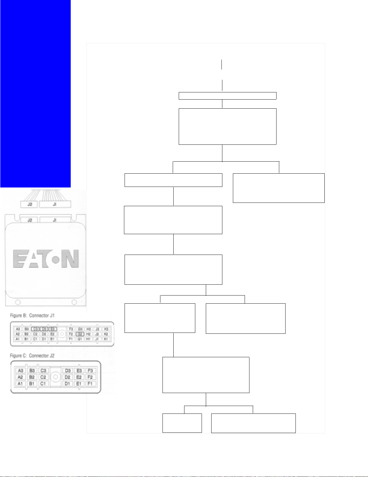
Continuation
Turn the ignition key “ON”.
Refer to Figure B below. Measure the
voltage between the harness connector
pins A3 and G1 [voltage = battery voltage. Is voltage correct?
YES
Turn ignition key “OFF”. A problem exists in vehicle interface
Refer to Figure B below. Place jumper
wire across vehicle interface harness
connector pins F1 and A3.
NO
harness or ignition voltage supply circuit breaker. Contact OEM for service
information.
Refer to Figure B below. Measure voltage between harness connector pins B3
and E1 [voltage = batter voltage]. Is volt-
age correct?
YES NO
Refer to Figure A at left.
Disconnect vehicle interface
harness J2 connector from
ECU.
Refer to Figure C at left. Measure
voltage between J1 connector pin B3
and J2 connector pin A3 [voltage =
battery voltage]. Is voltage correct?
YES
Test Complete Repair/replace vehicle interface
A problem exists in transmission
power relay or vehicle interface
harness. Contact OEM for service information.
NO
harness according to OEM service
information
14
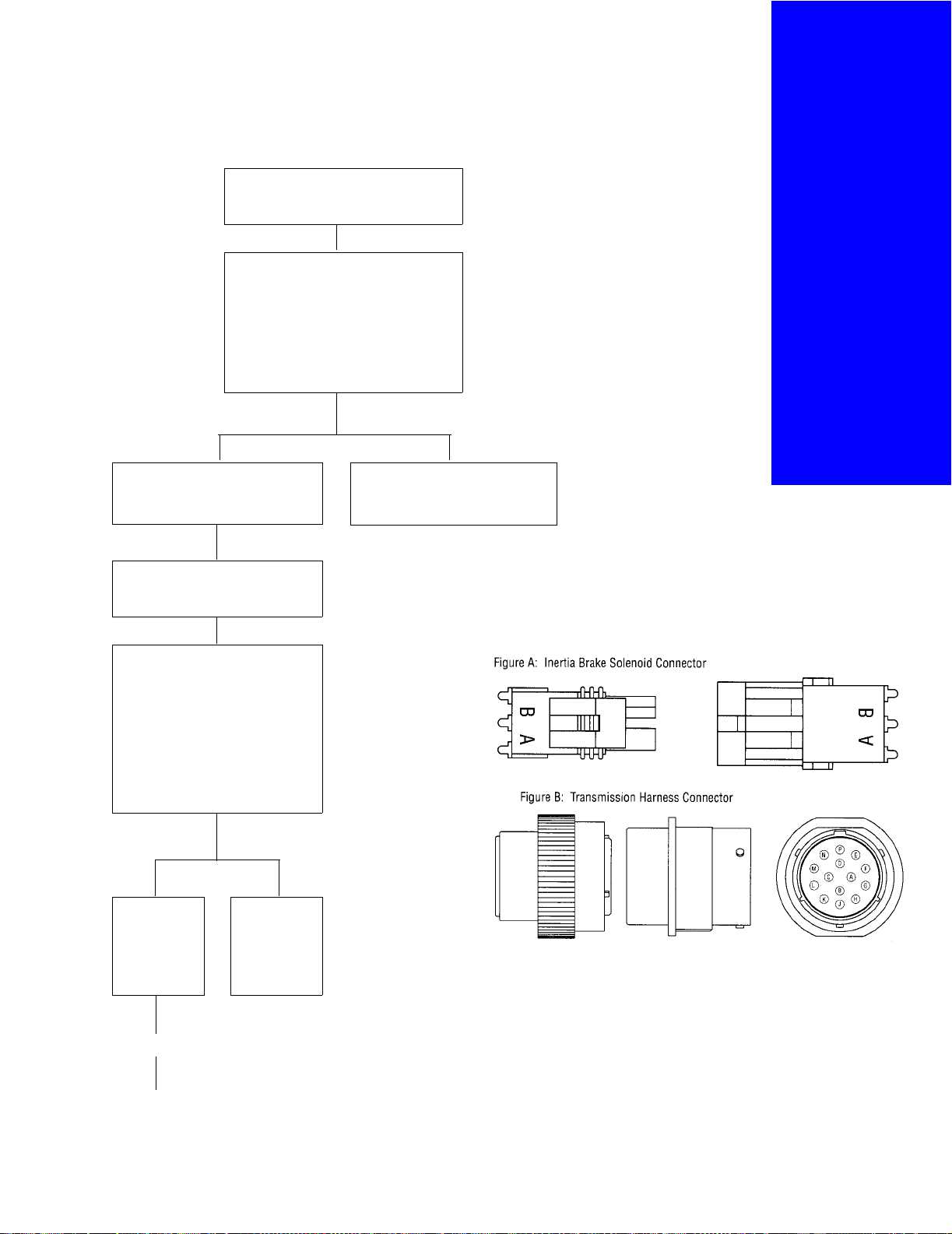
t
Before beginning test procedure:
1. Set parking brakes.
2. Perform Transmission Electrical Test.
3. Turn ignition key “OFF”.
Refer to Figure A below. Disconnect
inertia brake solenoid from the transmission electrical harness.
Measure resistance between inertia
brake solenoid connector pins [resistance = 11-18 ohms]. Measure resistance between inertia brake solenoid
and vehicle electrical ground [resistance = infinity]. Is resistance correct?
YES
Connect inertia brake solenoid to
transmission harness.
NO
Replace inertia brake solenoid.
I n e r t i a B r ak e
Solenoid
Coil Tes
For all questions
concerning
inspection,
removal,
replacement,
or adjustment
procedures,
refer to Eaton or
OEM Service and
Parts Literature.
Disconnect transmission harness
from vehicle interface harness.
Refer to Figure B below. Measure
resistance between transmission
harness pins G and H [resistance
= 11-18 ohms]. Measure resistance between transmission harness pin H and vehicle electrical
ground [resistance = infinity]. Is
resistance correct?
YES
Connect transmission harness to vehicle
interface harness.
NO
Replace transmission harness.
Continue
15

Inertia
Brake
Solenoid
Coil Test
For all questions
concerning
inspection,
removal,
replacement,
or adjustment
procedures,
refer to Eaton or
OEM Service and
Parts Literature.
Continuation
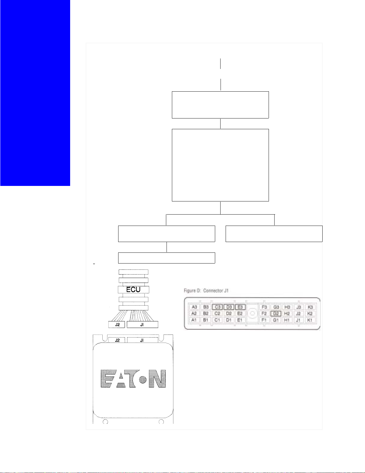
Refer to Figure C below. Disconnect
vehicle interface harness J1 connector
from transmission ECU.
YES
Refer to Figure D below. Measure resistance between vehicle interface harness
connector pins E1 and H1 [resistance =
11-18 ohms]. Measure resistance
between pin H1 and vehicle electrical
ground [resistance = infinity]. Is resis-
tance correct?
NO
YES NO
Replace transmission ECU. Replace vehicle interface harness
according to OEM service information.
Test complete
16

t
Before beginning test procedure:
1. Set parking brakes.
2. Perform Transmission Electrical Test.
3. Turn ignition key “OFF”.
Refer to Figure A below. Install 0-100 psi
air gauge in inertia brake air line. Gauge
should be installed in “T” fashion.
Inertia
Brake Tes
Start vehicle and allow air pressure to
reach governor cut off [90-125 psi].
With the vehicle at idle fully depress clutch
pedal and monitor air pressure gauge.
Does the inertia brake air pressure cycle
on and off?
Replace inertia brake according to
service manual.
For all questions
concerning
inspection,
removal,
replacement,
or adjustment
procedures,
refer to Eaton or
OEM Service and
Parts Literature.
NOYES
Refer to Figure B below. Disconnect vehicle interface harness connector J1 from
transmission ECU.
Refer to Figure C below. Place jumper wire
between pins G2 and E1.
Refer to Figure C below. Place jumper wire
between pins H1 and A3. Monitor pressure
gauge. Does the inertia brake air pressure
read 85-95 psi?
YES
Go to Inertia
Brake Switch
Test
NO
Remove air gauge
from inertia brake
air line.
Go to Inertia Brake
Air Supply Test
17
Inertia
Brake
S w i t c h
Test
Before beginning test procedure:
1. Set parking brakes.
2. Perform Transmission Electrical Test.
3. Turn ignition key “OFF”.
Refer to Figure A below. Disconnect vehicle interface harness connector J2 from the
transmission ECU.
For all questions
concerning
inspection,
removal,
replacement,
or adjustment
procedures,
refer to Eaton or
OEM Service and
Parts Literature.
Refer to Figure B below. Measure the resistance between pin F3 and vehicle electrical
ground [resistance = infinity]. Is resistance
correct?
YES NO
Fully depress the clutch pedal. Repair inertia brake switch according to
OEM service information.
Refer to Figure A below. Measure the
resistance between pin F3 and vehicle
electrical ground [resistance = 0-5
ohms]. Is resistance correct?
YES NO
Replce transmission ECU according to
transmission service manual.
Repair inertia
brake switch circuit according to
OEM service
information.
18

Before beginning test procedure:
1. Set parking brakes.
2. Perform Transmission Electrical Test.
3. Turn ignition key “OFF”.
Refer to Figure A below. Install 0-100 psi
air gauge in inertia brake solenoid air
regulator port.
I n e r t i a
Brake
A i r
S u pp l y
Test
Start the vehicle and allow air system to
reach governor cut-off [90-120 psi].
Monitor air pressure gauge. Does air
pressure equal 73-83 psi?
YES NO
Replace inertia brake solenoid
according to transmission service
manual.
Replace air filter regulator according
to transmission service manual.
For all questions
concerning
inspection,
removal,
replacement,
or adjustment
procedures,
refer to Eaton or
OEM Service and
Parts Literature.
19

Transmission
Converter
Open
Lamp
Test
Before beginning test procedure:
1. Set parking brakes.
2. Perform Transmission Electrical Test.
3. Turn ignition key “OFF”.
Refer to Figure A below. Disconnect vehicle
interface harness connector J1 from the
transmission ECU.
For all questions
concerning
inspection,
removal,
replacement,
or adjustment
procedures,
refer to Eaton or
OEM Service and
Parts Literature.
Refer to Figure B below. Place jumper wire
between pins G2 and E1. Place jumper wire
between pins C2 and A3. Does Converter
open lamp turn “ON”?
YES NO
Replace transmission ECU according
to OEM service information.
Replace converter open lamp and
inspect the vehicle interface harness.
Does condition still exist?
YES
Perform Tr an smission Electrical Test.
NO
Test Complete
20

Before beginning test procedure:
1. Set parking brakes.
2. Perform Transmission Electrical Test.
3. Turn ignition key “OFF”.
Refer to Figure A below. Disconnect engine
speed sensor from transmission electrical
harness.
Measure resistance between engine speed
sensor connector pins [resistance = 3k-4k
ohms]. Measure resistance between
engine speed sensor pin A and vehicle electrical ground [resistance = infinity]. Is
resistance correct?
Connect engine speed sensor to
transmission harness.
YES NO
Replace engine speed sensor.
Engine
Speed
Sensor
Test
For all questions
concerning
inspection,
removal,
replacement,
or adjustment
procedures,
refer to Eaton or
OEM Service and
Parts Literature.
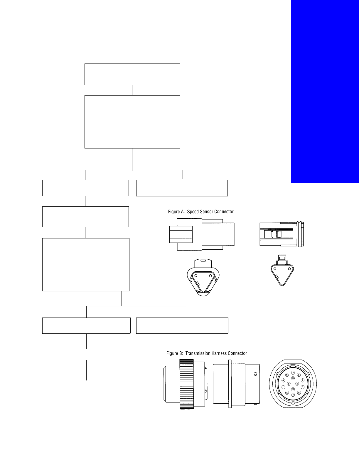
Refer to Figure B below. Disconnect
transmission harness from the vehicle interface harness.
Measure resistance between transmission harness pins N and P [resistance = 3k-4k ohms]. Measure
resistance between transmission
harness pin P and vehicle electrical
ground [resistance = infinity]. Is
resistance correct?
YES NO
Connect transmission harness to vehicle
interface harness.
Replace transmission harness.
Continue
21

Engine
Speed
Sensor
For all questions
concerning
inspection,
removal,
replacement,
or adjustment
procedures,
refer to Eaton or
OEM Service and
Parts Literature.
Test
Continuation
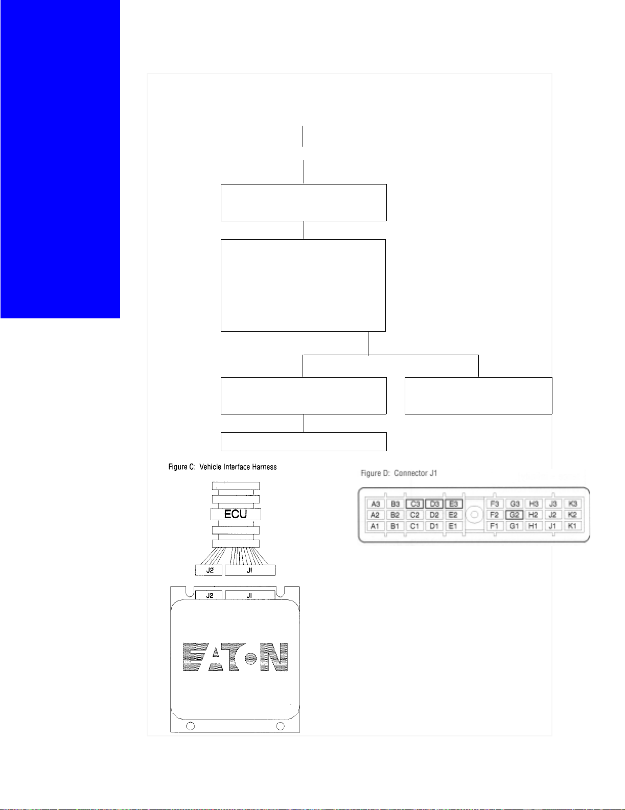
Refer to Figure C below. Disconnect
vehicle interface harness J1 connector
from transmission ECU.
Refer to Figure D below. Measure resistance between vehicle interface harness
connector pins J3 and K3 [resistance =
3k-4k ohms]. Measure resistance
between pin K3 and vehicle electrical
ground [resistance = infinity]. Is resis-
tance correct?
YES NO
Replace transmission ECU. Replace vehicle interface harness accord-
ing to OEM service information.
Test complete
22
Before beginning test procedure:
1. Set parking brakes.
2. Perform Transmission Electrical Test.
3. Turn ignition key “OFF”.
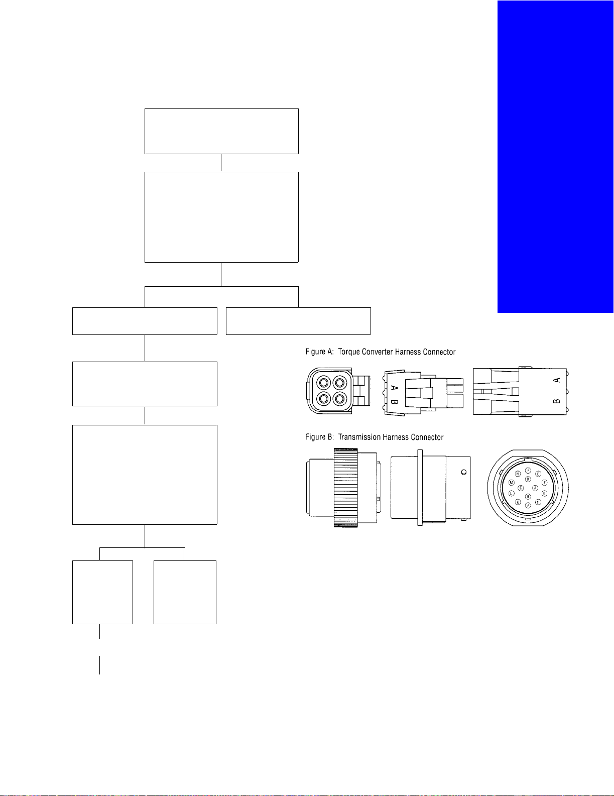
Refer to Figure A below. Disconnect
torque converter harness from transmission electrical harness.
Bypass/
Lockup
S o l e n o i d
Coil
Test
Measure resistance between torque
converter harness pins A and B [resistance = 2.5-4 ohms]. Measure resistance between torque converter
harness pin A and vehicle electrical
ground [resistance = infinity]. Is resis-
tance correct?
YES NO
Connect torque converter harness to
transmission harness.
Refer to Figure B below. Disconnect
transmission harness from the vehicle interface harness.
Measure resistance between transmission harness pins A and B [resistance = 2.5-4 ohms]. Measure
resistance between transmission
harness pin B and vehicle electrical
ground [resistance = infinity]. Is
resistance correct?
For all questions
concerning
inspection,
removal,
replacement,
or adjustment
procedures,
refer to Eaton or
OEM Service and
Parts Literature.
Replace torque converter harness.
YES
Connect transmission harness to vehicle
interface harness.
Continue
NO
Replace transmission harness.
23
Bypass/
Lockup
Solenoid
Coil
Before beginning test procedure:
1. Set parking brakes.
2. Perform Transmission Electrical Test.
3. Turn ignition key “OFF”.
For all questions
concerning
inspection,
removal,
replacement,
or adjustment
procedures,
refer to Eaton or
OEM Service and
Parts Literature.
Test
Continuation
Refer to Figure C below. Disconnect
vehicle interface harness J1 connector
from transmission ECU.
Refer to Figure D below. Measure resistance between vehicle interface harness
connector pins E1 and K2 [resistance =
2.5-4 ohms]. Measure resistance
between vehicle electrical ground pins E1
and C1 [resistance = 2.5-4 ohms]. Measure resistance between pin C1 and vehicle electrical ground [resistance infinity].
Is resistance correct?
YES
Replace transmission ECU. Replace vehicle interface harness
NO
according to OEM service information.
Test complete
24

Before beginning test procedure:
1. Set parking brakes.
2. Perform Transmission Electrical Test.
3. Turn ignition key “OFF”.
Disconnect torque converter harness
from transmission harness.
Refer to Figure A below. Measure resistance between torque converter harness
pins C and D [resistance = 2.5-4 ohms].
Is resistance correct?
YES NO
Refer to Figure A below. Measure
resistance between torque converter
harness pin C and vehicle electrical
ground [resistance = infinity]. Is
resistance correct?
Replace torque converter harness.
Interrupt
Clutch
So len oid
Coil
Test
For all questions
concerning
inspection,
removal,
replacement,
or adjustment
procedures,
refer to Eaton or
OEM Service and
Parts Literature.
YES
Turn ignition key
“ON”.
Refer to Figure A
at right. Measure
voltage between
transmission harness pins C and
D [voltage = battery voltage]. Is
voltage correct?
YESNO
Depress clutch
pedal.
NO
Replace torque
converter harness.
Continue Continue
25
Interrupt
Clutch
Solenoid
Coil
Test
Continuation Continuation
For all questions
concerning
inspection,
removal,
replacement,
or adjustment
procedures,
refer to Eaton or
OEM Service and
Parts Literature.
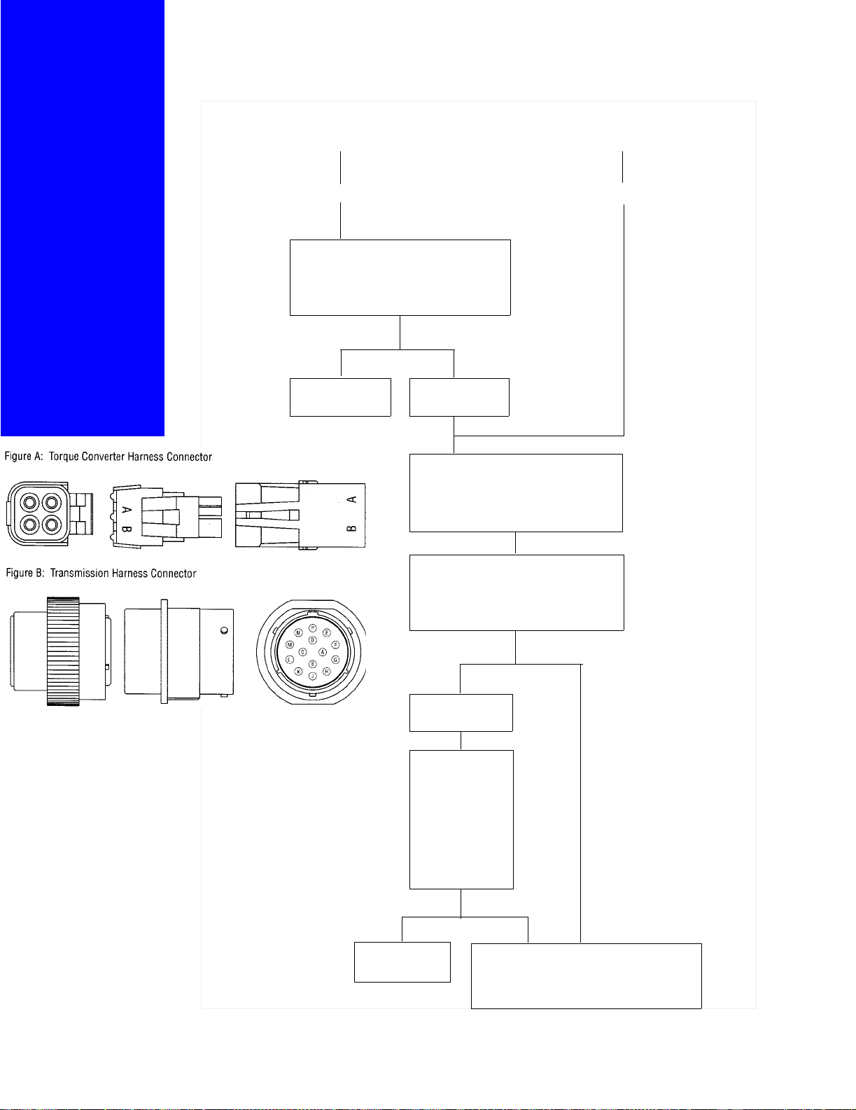
Refer to Figure A below. Measure voltage between transmission harness pins
C and D [voltage = 0 volts]. Is voltage
correct?
YES NO
Test Complete Release clutch
pedal.
Connect torque converter harness to
transmission harness. Disconnect
transmission harness from vehicle
interface harness.
Refer to Figure B below. Measure voltage between vehicle interface harness
pins C and D [voltage = battery voltage]. Is voltage correct?
YES NO
26
Depress clutch
pedal.
Refer to Figure B
at left. Measure
voltage between
vehicle interface
harness pins C
and D [voltage = 0
volts].
correct
YES NO
Replace transmission harness
Is voltage
?
A problem exists in the vehicle interface
harness, clutch switch or power
connect relay. Contact OEM for service
information.
Before beginning test procedure:
1. Set parking brakes.
2. Perform Transmission Electrical Test.
3. Turn ignition key “OFF”.
Set Parking brake and place shift lever in
neutral position.
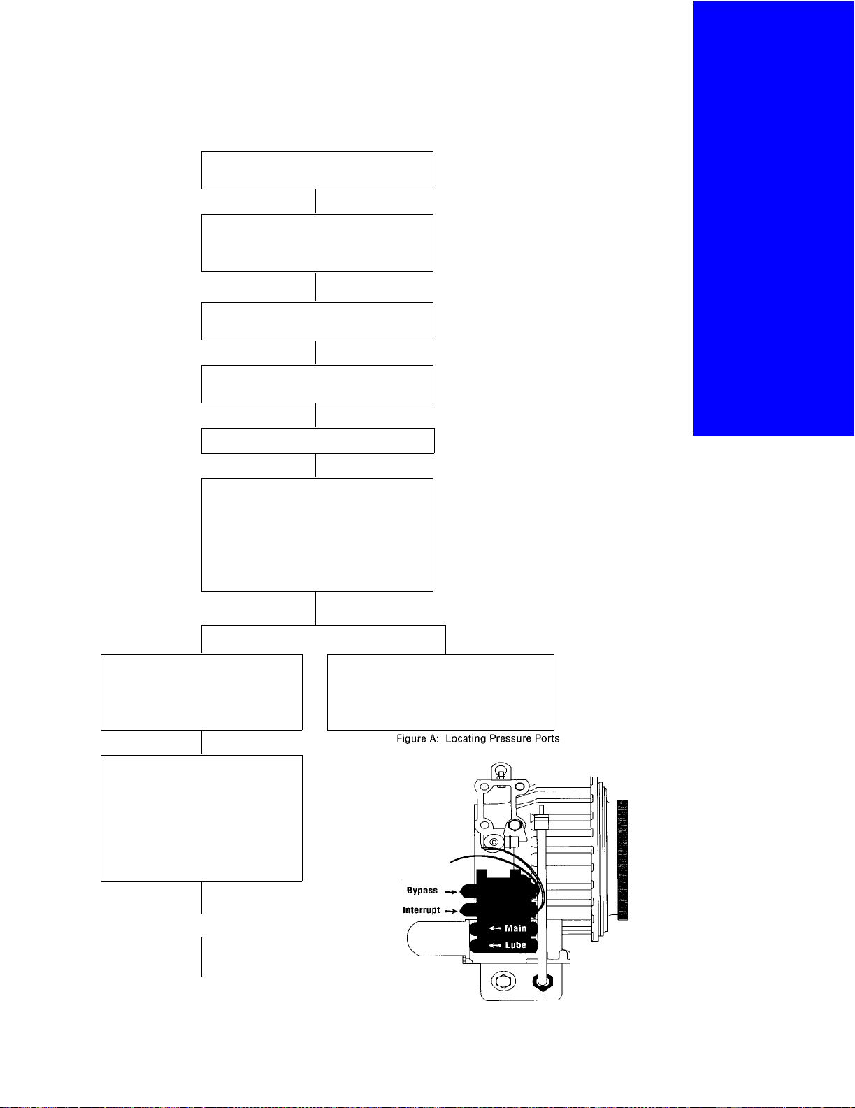
Refer to Figure A below. Connect 0-300
psi gauges to main interrupt and bypass/
lockup torque converter ports.
Refer to Figure A below. Connect 0-100
psi gauge to torque converter lube port.
Start vehicle and allow transmission temperature to reach 180-220
Depress clutch pedal.
°F.
H y d r a u l i c
S y s t e m
Test
For all questions
concerning
inspection,
removal,
replacement,
or adjustment
procedures,
refer to Eaton or
OEM Service and
Parts Literature.
Monitor pressure gauges.
Main pressure: 225-255 psi
Interrupt pressure: 0 psi
Bypass/lockup pressure: 0 psi
Lube pressure: 20-35 psi
Are the pressures correct?
YES NO
Release clutch pedal. Inspect/clean oil strainer in oil pan.
Replace hydraulic valve. If conflict still
exists, a failure has occurred in the
hydraulic system.
Monitor pressure gauges.
Main pressure: 225-255 psi
Interrupt pressure:
Bypass/lockup pressure: 0 psi
Lube pressure: 15-20 psi
Are the pressures correct?
±5 psi of main
Continue
27

Hydraulic
System
Test
Continuation
For all questions
concerning
inspection,
removal,
replacement,
or adjustment
procedures,
refer to Eaton or
OEM Service and
Parts Literature.
YES NO
Increase engine rpm to 1600 rpm to
lock up the torque converter. Torque
converter open light turns “OFF”.
Note: Light should come back on at
1400 rpm.
Monitor pressure gauges.
Main pressure: 225-255 psi
Interrupt pressure:
Bypass/lockup pressure:
Lube pressure: 15-20 psi
Are the pressures correct?
Test complete Replace hydrau-
±5 psi of main
±5 psi of
main
lic valve. If conflict still exists, a
failure has
occurred in the
hydraulic system.
Replace hydraulic valve. If conflict
still exists, a failure has occurred in
the hydraulic system.
28
Before beginning test procedure:
1. Set parking brakes.
2. Perform Transmission Electrical Test.
3. Turn ignition key “OFF”.
Refer to Figure A below. Disconnect
input shaft speed sensor from the transmission electrical harness.
Measure resistance between input shaft
speed sensor connector pins [resistance
= 3k-4k ohms]. Measure resistance
between input shaft speed sensor pin A
and vehicle electrical ground [resistance
= infinity].
Is resistance correct?
YES
NO
Input
Shaft
Speed
Sensor
Test
For all questions
concerning
inspection,
removal,
replacement,
or adjustment
procedures,
refer to Eaton or
OEM Service and
Parts Literature.
Connect input shaft speed sensor to
transmission harness.
Refer to Figure B below. Disconnect
transmission harness from vehicle
interface harness.
Measure resistance between transmission harness pins J and K [resistance = 3k-4k ohms]. Measure
resistance between transmission harness pin K and vehicle electrical
ground [resistance = infinity].
Is resistance correct?
YES NO
Connect transmission harness to
transmission electrical harness.
Replace the input shaft speed sensor.
Replace the transmission harness.
Continue
29

Input
Shaft
Sensor
Test
Continuation
For all questions
concerning
inspection,
removal,
replacement,
or adjustment
procedures,
refer to Eaton or
OEM Service and
Parts Literature.
Refer to Figure C below. Disconnect
vehicle interface harness J1 connector
from transmission ECU.
Refer to Figure D below. Measure resistance between vehicle interface harness
connector pin G3 and H3 [resistance = 3k4k ohms]. Measure resistance between
pin H3 and vehicle electrical ground
[resistance = infinity].
Is resistance correct?
YES
Replace transmission ECU. Replace vehicle interface harness
Test Complete
NO
according to OEM service information.
30

Before beginning test procedure:
1. Set parking brakes.
2. Perform Transmission Electrical Test.
3. Turn ignition key “OFF”.
Refer to Figure A below. Disconnect output shaft speed sensor from the transmission electrical harness.
Output
Shaft
Speed
Sensor
Test
Measure resistance between output shaft
speed sensor connector pins [resistance =
3k-4k ohms]. Measure resistance
between output shaft speed sensor pin A
and vehicle electrical ground [resistance =
infinity].
Is resistance correct?
YES
Connect output shaft speed sensor to
transmission harness.
Refer to Figure B below. Disconnect
transmission harness from vehicle
interface harness.
Measure resistance between transmission harness pins E and F [resistance =
3k-4k ohms]. Measure resistance
between transmission harness pin F
and vehicle electrical ground [resistance = infinity].
Is resistance correct?
NO
Replace the output shaft speed sensor.
For all questions
concerning
inspection,
removal,
replacement,
or adjustment
procedures,
refer to Eaton or
OEM Service and
Parts Literature.
YES
Connect transmission harness to
transmission electrical harness.
Continue
NO
Replace the transmission harness.
31
Output
Shaft
Sensor
Test
Continuation
For all questions
concerning
inspection,
removal,
replacement,
or adjustment
procedures,
refer to Eaton or
OEM Service and
Parts Literature.
Refer to Figure C below. Disconnect
vehicle interface harness J1 connector
from transmission ECU.
Refer to Figure D below. Measure resistance between vehicle interface harness
connector pins A1 and B1 [resistance =
3k-4k ohms]. Measure resistance
between pin B1 and vehicle electrical
ground [resistance = infinity]. Is resis-
tance correct?
YES NO
Replace transmission ECU. Replace vehicle interface harness
according to OEM service information.
Test complete
32

System Overview
Appendix I
For all questions
concerning
inspection,
removal,
replacement,
or adjustment
procedures,
refer to Eaton or
OEM Service and
Parts Literature.
33

Appendix I
For all questions
concerning
inspection,
removal,
replacement,
or adjustment
procedures,
refer to Eaton or
OEM Service and
Parts Literature.
Electrical Schematic
34


Copyright Eaton Corporation, 2012.
Eaton hereby grant their customers,
vendors, or distributors permission
to freely copy, reproduce and/or
distribute this document in printed
format. It may be copied only in
its entirety without any changes or
modifications. THIS INFORMATION
IS NOT INTENDED FOR SALE OR
RESALE, AND THIS NOTICE MUST
REMAIN ON ALL COPIES.
Note: Features and specifications
listed in this document are subject to
change without notice and represent
the maximum capabilities of the
software and products with all options
installed. Although every attempt has
been made to ensure the accuracy of
information contained within, Eaton
makes no representation about the
completeness, correctness or accuracy
and assumes no responsibility for
any errors or omissions. Features and
functionality may vary depending on
selected options.
For spec’ing or service assistance,
call 1-800-826-HELP (4357) or visit
www.eaton.com/roadranger.
In Mexico, call 001-800-826-4357.
Roadranger: Eaton and trusted partners
providing the best products and services in the
industry, ensuring more time on the road.
Eaton Corporation
Vehicle Group
P.O. Box 4013
Kalamazoo, MI 49003 USA
800-826-HELP (4357)
www.eaton.com/roadranger
Printed in USA

For parts or service call us
Pro Gear & Transmission, Inc.
1 (877) 776-4600
(407) 872-1901
parts@eprogear.com
906 W. Gore St.
Orlando, FL 32805
 Loading...