


AV SURROUND RECEIVER
AVR-2307
OPERATING INSTRUCTIONS
BEDIENUNGSANLEITUNG
MODE D’EMPLOI
ISTRUZIONI PER L’USO
INSTRUCCIONES DE FUNCIONAMIENTO
GEBRUIKSAANWIJZING
BRUKSANVISNING

ENGLISH |
DEUTSCH |
FRANCAIS |
ITALIANO |
ESPAÑOL |
NEDERLANDS |
SVENSKA |
|
|
|
|
|
|
|
|
|
|
|
|
|
|
|
|
|
|
||||||||||||||||||||||
|
¢SAFETY PRECAUTIONS |
|
|
|
|
|
|
|
¢ NOTE ON USE / HINWEISE ZUM GEBRAUCH / OBSERVATIONS RELATIVES A L’UTILISATION / |
|||||||||||||||||||||||||||||||||||||
|
|
|
|
|
|
|
|
|
|
|
|
|
|
|
NOTE SULL’USO / NOTAS SOBRE EL USO / ALVORENS TE GEBRUIKEN / OBSERVERA |
|
|
|||||||||||||||||||||||||||||
|
|
|
|
|
|
|
|
|
|
|
|
|
|
|
|
|
||||||||||||||||||||||||||||||
|
|
|
|
CAUTION |
|
|
|
|
|
|
|
|
|
|
|
|
|
|
|
|
|
|
|
|
|
|
|
|
|
|
|
|
|
|
|
|
|
|
|
|
|
|
|
|||
|
|
|
|
|
|
|
|
|
|
|
|
|
|
|
|
|
|
|
|
|
|
|
|
|
|
|
|
|
|
|
|
|
|
|
|
|
|
|
|
|
|
|||||
|
|
|
|
RISK OF ELECTRIC SHOCK |
|
|
|
|
|
|
|
|
|
|
|
|
|
|
|
|
|
|
|
|
|
|
|
|
|
|
|
|
|
|
|
|
|
|
|
|
|
|||||
|
|
|
|
DO NOT OPEN |
|
|
|
|
|
|
|
|
|
|
|
|
|
|
|
|
|
|
|
|
|
|
|
|
|
|
|
|
|
|
|
|
|
|
|
|
|
|
|
|||
|
CAUTION: |
|
|
|
|
|
|
|
|
|
|
|
|
|
|
|
|
|
|
|
|
|
|
|
|
|
|
|
|
|
|
• Unplug the power cord when not using the set |
|
|
|
|
|
|||||||||
|
TO REDUCE THE RISK OF ELECTRIC SHOCK, DO NOT REMOVE |
|
|
|
|
|
|
|
|
|
|
|
|
|
|
|
|
|
|
|
|
|
• Do not let insecticides, benzene, and thinner |
|||||||||||||||||||||||
|
|
|
|
|
|
|
|
|
|
|
|
|
|
|
• Handle the power cord carefully. |
|
|
for long periods of time. |
|
|
||||||||||||||||||||||||||
|
|
|
|
|
|
|
|
|
|
|
|
|
|
|
|
|
|
|
||||||||||||||||||||||||||||
|
|
|
|
|
|
|
|
|
|
|
|
|
|
|
|
|
|
|
||||||||||||||||||||||||||||
|
COVER (OR BACK). NO USER-SERVICEABLE PARTS INSIDE. |
|
• Avoid high temperatures. |
|
|
|
|
|
Hold the plug when unplugging the cord. |
|
• Wenn |
das Gerät |
eine längere |
Zeit nicht |
come in contact with the set. |
|
|
|||||||||||||||||||||||||||||
|
REFER SERVICING TO QUALIFIED SERVICE PERSONNEL. |
|
|
|
Allow for sufficient heat dispersion when |
• Gehen Sie vorsichtig mit dem Netzkabel um. |
|
verwendet werden soll, trennen Sie das |
• Lassen Sie das Gerät nicht mit Insektiziden, |
|||||||||||||||||||||||||||||||||||||
|
|
|
|
installed on a rack. |
|
|
|
|
|
|
|
|
Halten Sie das Kabel am Stecker, wenn Sie den |
|
Netzkabel vom Netzstecker. |
|
Benzin oder Verdünnungsmitteln in Berührung |
|||||||||||||||||||||||||||||
|
|
|
The lightning |
flash |
with arrowhead symbol, |
within |
an |
|
• Vermeiden Sie hohe Temperaturen. |
|
|
Stecker herausziehen. |
|
|
|
• Débrancher le cordon |
d’alimentation lorsque |
kommen. |
|
|
|
|
||||||||||||||||||||||||
|
|
|
|
Beachten |
Sie, |
daß |
eine |
ausreichend |
• Manipuler le |
cordon d’alimentation |
avec |
|
l’appareil n’est pas utilisé pendant de longues |
• Ne pas mettre en contact des insecticides, du |
||||||||||||||||||||||||||||||||
|
|
|
equilateral triangle, |
is intended |
to |
alert the user to |
the |
|
Luftzirkulation gewährleistet wird, wenn das |
précaution. |
|
|
|
|
|
|
périodes. |
|
|
|
|
benzène et un diluant avec l’appareil. |
|
|||||||||||||||||||||||
|
|
|
|
Tenir la prise lors du débranchement du cordon. |
• Disinnestate il filo |
di |
alimentazione quando |
• Assicuratevvi che l’unità non venga in contatto |
||||||||||||||||||||||||||||||||||||||
|
|
|
presence of uninsulated “dangerous voltage” within the |
|
Gerät auf ein Regal gestellt wird. |
|
|
|
||||||||||||||||||||||||||||||||||||||
|
|
|
|
• Eviter des températures élevées |
|
|
|
• Manneggiate il filo di alimentazione con cura. |
|
avete l’intenzione di non usare il filo di |
con insetticidi, benzolo o solventi. |
|
||||||||||||||||||||||||||||||||||
|
|
|
product’s enclosure that may be of sufficient magnitude to |
|
Tenir |
compte d’une |
dispersion |
de |
chaleur |
Agite per la spina quando scollegate il cavo dalla |
|
alimentazione per un lungo periodo di tempo. |
• No permita el contacto de insecticidas, gasolina |
|||||||||||||||||||||||||||||||||
|
|
|
constitute a risk of electric shock to persons. |
|
|
|
|
suffisante lors de l’installation sur une étagère. |
presa. |
|
|
|
|
|
• Desconecte el cordón de energía cuando no |
y diluyentes con el equipo. |
|
|
||||||||||||||||||||||||||||
|
|
|
|
|
|
|
• Maneje el cordón de energía con cuidado. |
|
utilice el equipo por mucho tiempo. |
|
• Laat geen |
insektenverdelgende middelen, |
||||||||||||||||||||||||||||||||||
|
|
|
|
|
|
|
|
|
|
|
|
|
|
|
• Evitate di esporre l’unità a temperature alte. |
|
|
|||||||||||||||||||||||||||||
|
|
|
The exclamation |
point within |
an |
equilateral |
triangle is |
|
Assicuratevi che ci sia un’adeguata dispersione |
Sostenga el enchufe cuando desconecte el |
• Neem |
altijd het netsnoer uit het |
stopkontakt |
benzine of verfverdunner met dit apparaat in |
||||||||||||||||||||||||||||||||
|
|
|
|
del calore quando installate l’unità in un mobile |
cordón de energía. |
|
|
|
|
wanneer het apparaat gedurende een lange |
kontakt komen. |
|
på spraybruk, |
|||||||||||||||||||||||||||||||||
|
|
|
intended to alert |
the user to the |
presence of |
important |
|
per componenti audio. |
|
|
|
|
|
|
• Hanteer het netsnoer voorzichtig. |
|
|
periode niet wordt gebruikt. |
|
• Se till att |
inte insektsmedel |
|||||||||||||||||||||||||
|
|
|
|
|
|
|
|
|
|
Houd het snoer bij de stekker vast wanneer |
• Koppla ur nätkabeln om apparaten inte kommer |
bensen och thinner kommer i kontakt med |
||||||||||||||||||||||||||||||||||
|
|
|
operating and maintenance (servicing) instructions in the |
|
• Evite altas temperaturas |
|
|
|
|
|
||||||||||||||||||||||||||||||||||||
|
|
|
|
Permite la suficiente dispersión del calor |
deze moet worden aanof losgekoppeld. |
|
|
att användas i lång tid. |
|
|
apparatens hölje. |
|
|
|
||||||||||||||||||||||||||||||||
|
|
|
literature accompanying the appliance. |
|
|
|
|
cuando está instalado en la consola. |
|
|
• Hantera nätkabeln varsamt. |
|
|
|
|
|
|
|
|
|
|
|
|
|
|
|
||||||||||||||||||||
|
|
|
|
|
|
|
|
|
|
|
|
|
|
|
|
|
|
|
|
|
|
|
|
|||||||||||||||||||||||
|
|
|
|
|
|
|
|
|
|
|
|
|
|
|
• Vermijd hoge temperaturen. |
|
|
|
|
Håll i kabeln när den kopplas från el-uttaget. |
|
|
|
|
|
|
|
|
|
|
|
|
||||||||||||||
|
WARNING: |
|
|
|
|
|
|
|
|
|
|
Zorg voor een degelijk hitteafvoer indien het |
|
|
|
|
|
|
|
|
|
|
|
|
|
|
|
|
|
|
|
|||||||||||||||
|
|
|
|
|
|
|
|
|
|
|
apparaat op een rek wordt geplaatst. |
|
|
|
|
|
|
|
|
|
|
|
|
|
|
|
|
|
|
|
|
|
||||||||||||||
|
TO REDUCE THE RISK OF FIRE OR ELECTRIC SHOCK, DO NOT |
|
• Undvik höga temperaturer. |
|
|
|
|
|
|
|
|
|
|
|
|
|
|
|
|
|
|
|
|
|
|
|
||||||||||||||||||||
|
|
Se till att det finns möjlighet till god |
|
|
|
|
|
|
|
|
|
|
|
|
|
|
|
|
|
|
|
|||||||||||||||||||||||||
|
EXPOSE THIS APPLIANCE TO RAIN OR MOISTURE. |
|
|
|
|
värmeavledning vid montering i ett rack. |
|
|
|
|
|
|
|
|
• Keep the apparatus free from moisture, water, and |
• Never disassemble or modify the set in any |
||||||||||||||||||||||||||||||
|
|
|
|
|
|
|
|
|
|
|
|
|
||||||||||||||||||||||||||||||||||
|
|
|
|
|
|
|
|
|
|
|
|
|
|
|
|
|
|
|
|
|
|
|
|
|
|
|
|
|
|
|
|
|
|
|
||||||||||||
|
|
|
|
|
|
|
|
|
|
|
|
|
|
|
|
|
|
|
|
|
|
|
|
|
|
|
|
|
|
|
|
|
|
|
||||||||||||
|
• |
DECLARATION OF CONFORMITY |
|
|
|
|
|
|
|
|
|
|
|
|
|
|
|
|
|
|
|
|
|
|
|
|
|
|
|
|
||||||||||||||||
|
|
|
|
|
|
|
|
|
|
|
|
|
|
|
|
|
|
|
|
|
|
|
|
|
|
|
|
|
way. |
|
|
|
|
|||||||||||||
|
|
We declare under our sole responsibility that this product, to which this declaration |
|
|
|
|
|
|
|
|
|
|
|
|
|
|
|
|
|
|
|
|
|
|
dust. |
|
|
|
|
|
• Versuchen Sie niemals das Gerät auseinander |
|||||||||||||||
|
|
|
|
|
|
|
|
|
|
|
|
|
|
|
|
• Do not let foreign objects in the set. |
|
• |
Halten Sie das Gerät von Feuchtigkeit, Wasser |
|||||||||||||||||||||||||||
|
|
relates, is in conformity with the following standards: |
|
|
|
|
|
|
|
|
|
|
|
|
|
|
|
|
|
|
|
|
|
zu nehmen oder auf jegliche Art zu verändern. |
||||||||||||||||||||||
|
|
|
|
|
|
|
|
|
|
|
|
|
|
|
|
|
|
|
|
|
|
• Keine fremden |
Gegenstände in das |
Gerät |
|
und Staub fern. |
|
|
|
|||||||||||||||||
|
|
EN60065, EN55013, EN55020, EN61000-3-2 and EN61000-3-3. |
|
|
|
|
|
* (For sets with ventilation holes) |
|
|
|
|
|
• Ne jamais démonter ou modifier l’appareil d’une |
||||||||||||||||||||||||||||||||
|
|
|
|
|
|
|
|
kommen lassen. |
|
|
|
• |
Protéger |
l’appareil |
contre l’humidité, l’eau et |
|||||||||||||||||||||||||||||||
|
|
|
|
|
|
|
|
|
|
|
manière ou d’une autre. |
|
|
|||||||||||||||||||||||||||||||||
|
|
Following the provisions of 73/23/EEC, 89/336/EEC and 93/68/EEC Directive. |
|
|
|
• Do not obstruct the ventilation holes. |
|
|
• Ne pas laisser |
des objets |
étrangers |
dans |
|
lapoussière. |
|
|
|
|
|
|||||||||||||||||||||||||||
|
|
|
|
|
|
|
|
|
|
|
• Non smontate mai, |
nè modificate l’unità |
in |
|||||||||||||||||||||||||||||||||
|
|
|
|
|
|
|
|
|
|
|
|
|
|
|
• Die Belüftungsöffnungen dürfen nicht verdeckt |
l’appareil. |
|
|
|
|
|
• |
Tenete l’unità lontana dall’umidità, dall’acqua e |
|||||||||||||||||||||||
|
• |
ÜBEREINSTIMMUNGSERKLÄRUNG |
|
|
|
|
|
|
|
|
|
|
|
|
nessun modo. |
|
|
|
||||||||||||||||||||||||||||
|
|
|
|
|
|
|
|
werden. |
|
|
|
|
|
|
|
|
|
|
|
• E’ importante che nessun oggetto è inserito |
|
dalla polvere. |
|
|
|
|
|
|
||||||||||||||||||
|
|
|
|
|
|
|
|
|
|
|
|
|
|
|
|
|
|
|
|
|
|
|
• Nunca desarme o |
modifique |
el equipo |
de |
||||||||||||||||||||
|
|
Wir erklären unter unserer Verantwortung, daß dieses Produkt, auf das sich diese |
|
• Ne pas obstruer les trous d’aération. |
|
|
all’interno dell’unità. |
|
|
|
• |
Mantenga el equipo libre de humedad, agua y |
||||||||||||||||||||||||||||||||||
|
|
|
|
|
|
|
|
ninguna manera. |
|
|
|
|||||||||||||||||||||||||||||||||||
|
|
Erklärung bezieht, den folgenden Standards entspricht: |
|
|
|
|
|
|
• Non coprite i fori di ventilazione. |
|
|
|
• No deje objetos extraños dentro del equipo. |
|
polvo. |
|
|
|
|
|
|
|
|
|||||||||||||||||||||||
|
|
|
|
|
|
|
|
|
|
|
|
|
|
|
|
|
• Nooit dit apparaat demonteren of op andere |
|||||||||||||||||||||||||||||
|
|
EN60065, EN55013, EN55020, EN61000-3-2 und EN61000-3-3. |
|
|
|
|
• No obstruya los orificios de ventilación. |
|
• Laat geen vreemde voorwerpen in dit apparaat |
• Laat geen vochtigheid, |
water of stof in het |
wijze modifiëren. |
|
|
|
|||||||||||||||||||||||||||||||
|
|
Entspricht den Verordnungen der Direktive 73/23/EEC, 89/336/EEC und 93/68/EEC. |
|
• De ventilatieopeningen |
mogen |
niet |
worden |
vallen. |
|
|
|
|
|
|
apparaat binnendringen. |
|
• Ta inte isär apparaten och försök inte bygga om |
|||||||||||||||||||||||||||||
|
|
|
beblokkeerd. |
|
|
|
|
|
|
|
|
• Se till att främmande föremål inte tränger in i |
• |
Utsätt |
inte apparaten |
för fukt, |
vatten och |
|||||||||||||||||||||||||||||
|
|
|
|
|
|
|
|
|
|
|
|
|
|
|
|
|
|
|
|
|
|
|
den. |
|
|
|
|
|||||||||||||||||||
|
• |
DECLARATION DE CONFORMITE |
|
|
|
|
|
|
|
|
• Täpp inte till ventilationsöppningarna. |
|
|
apparaten. |
|
|
|
|
|
|
damm. |
|
|
|
|
|
|
|
|
|||||||||||||||||
|
|
|
|
|
|
|
|
|
|
|
|
|
|
|
|
|
|
|
|
|
|
|
|
|
|
|||||||||||||||||||||
|
|
Nous déclarons sous notre seule responsabilité que l’appareil, auquel se réfère cette |
|
CAUTION: |
|
|
|
|
|
|
|
|
• Das Gerät sollte keinerlei Flüssigkeit, also |
• Non |
posizionare |
sull'apparecchiatura |
WAARSCHUWING: |
|
|
|||||||||||||||||||||||||||
|
|
déclaration, est conforme aux standards suivants: |
|
|
|
|
|
|
|
|
|
|
|
|
|
|
|
|
|
|||||||||||||||||||||||||||
|
|
|
|
|
|
|
|
|
• The ventilation should not be impeded by |
keinem Tropfen oder Spritzen ausgesetzt |
|
fiamme |
libere, |
come ad esempio le |
• De ventilatie mag niet worden belemmerd |
|||||||||||||||||||||||||||||||
|
|
EN60065, EN55013, EN55020, EN61000-3-2 et EN61000-3-3. |
|
|
|
|
|
|||||||||||||||||||||||||||||||||||||||
|
|
|
|
|
|
covering |
the ventilation |
openings with |
werden. |
|
|
|
|
|
|
candele accese. |
|
|
|
door de ventilatieopeningen af te dekken |
||||||||||||||||||||||||||
|
|
D’après les dispositions de la Directive 73/23/EEC, 89/336/EEC et 93/68/EEC. |
|
|
|
|
|
|
|
|
|
|
|
|
||||||||||||||||||||||||||||||||
|
|
|
|
|
items, such as newspapers, tablecloths, |
• Auf dem Gerät sollten keinerlei mit |
• Prestare attenzione agli aspetti legati alla |
met bijvoorbeeld kranten, een tafelkleed, |
||||||||||||||||||||||||||||||||||||||
|
|
|
|
|
|
|
|
|
|
|
|
|
|
|
||||||||||||||||||||||||||||||||
|
• |
DICHIARAZIONE DI CONFORMITÀ |
|
|
|
|
|
|
|
|
curtains, etc. |
|
|
|
|
|
|
|
|
Flüssigkeit |
gefüllten |
Behälter |
wie |
|
tutela dell'ambiente quando si smaltisce la |
gordijnen, enz. |
|
|
|
|||||||||||||||||
|
|
Dichiariamo con piena responsabilità che questo prodotto, al quale la nostra |
|
• No naked flame sources, such as lighted |
beispielsweise Vasen aufgestellt werden. |
|
batteria. |
|
|
|
|
• Plaats geen open vlammen, bijvoorbeeld |
||||||||||||||||||||||||||||||||||
|
|
dichiarazione si riferisce, è conforme alle seguenti normative: |
|
|
|
|
candles, should be placed on the |
ATTENTION: |
|
|
|
|
|
• L’apparecchiatura non deve essere esposta |
een brandende kaars, op het apparaat. |
|
||||||||||||||||||||||||||||||
|
|
EN60065, EN55013, EN55020, EN61000-3-2 e EN61000-3-3. |
|
|
|
|
apparatus. |
|
|
|
|
|
|
|
|
|
|
|
• La ventilation ne doit pas être gênée en |
|
a gocciolii o spruzzi. |
|
|
• Houd u steeds aan de milieuvoorschriften |
||||||||||||||||||||||
|
|
|
|
|
|
• Attention |
should |
be |
drawn |
to |
the |
• Non |
posizionare |
sull'apparecchiatura |
wanneer u gebruikte batterijen wegdoet. |
|||||||||||||||||||||||||||||||
|
|
In conformità con le condizioni delle direttive 73/23/EEC, 89/336/EEC e 93/68/EEC. |
|
recouvrant les ouvertures de la ventilation |
||||||||||||||||||||||||||||||||||||||||||
|
|
|
environmental aspects of battery disposal. |
|
nessun oggetto contenete liquidi, come ad |
• Stel het apparaat niet bloot aan druppels of |
||||||||||||||||||||||||||||||||||||||||
|
|
QUESTO PRODOTTO E’ CONFORME |
|
|
|
|
|
|
|
|
avec des objets tels que journaux, rideaux, |
|
||||||||||||||||||||||||||||||||||
|
|
|
|
|
|
|
|
|
|
• Do |
not expose |
the |
set |
to |
dripping |
or |
|
esempio i vasi. |
|
|
|
spatten. |
|
|
|
|
||||||||||||||||||||
|
|
AL D.M. 28/08/95 N. 548 |
|
|
|
|
|
|
|
|
|
|
tissus, etc. |
|
|
|
|
|
|
|
|
|
|
|
|
|
||||||||||||||||||||
|
|
|
|
|
|
|
|
|
|
|
|
splashing fluids. |
|
|
|
|
|
|
|
|
|
|
|
|
|
PRECAUCIÓN: |
|
|
|
• Plaats geen voorwerpen gevuld met water, |
||||||||||||||||
|
• |
DECLARACIÓN DE CONFORMIDAD |
|
|
|
|
|
|
|
|
|
|
|
|
|
|
|
• Aucune flamme nue, par exemple |
une |
|
|
|
||||||||||||||||||||||||
|
|
|
|
|
|
|
|
• No |
objects filled with liquids, such |
as |
|
|
|
bijvoorbeeld een vaas, op het apparaat. |
|
|||||||||||||||||||||||||||||||
|
|
|
|
|
|
|
|
bougie, ne doit être placée sur l’appareil. |
• La ventilación no |
debe quedar obstruida |
|
|||||||||||||||||||||||||||||||||||
|
|
Declaramos bajo nuestra exclusiva responsabilidad que este producto al que hace |
|
vases, shall be placed on the apparatus. |
|
|
|
|
|
|||||||||||||||||||||||||||||||||||||
|
|
|
• Veillez à respecter l’environnement lorsque |
|
por hacerse cubierto las aperturas con |
OBSERVERA: |
|
|
|
|||||||||||||||||||||||||||||||||||||
|
|
referencia esta declaración, está conforme con los siguientes estándares: |
|
|
|
|
|
|
|
|
|
|
|
|
|
|
|
|
|
|
|
|
||||||||||||||||||||||||
|
|
EN60065, EN55013, EN55020, EN61000-3-2 y EN61000-3-3. |
|
|
|
|
ACHTUNG: |
|
|
|
|
|
|
|
|
vous jetez les piles usagées. |
|
|
objetos |
como |
periódicos, |
manteles, |
• Ventilationen bör inte förhindras genom att |
|||||||||||||||||||||||
|
|
Siguiendo las provisiones de las Directivas 73/23/EEC, 89/336/EEC y 93/68/EEC. |
|
|
• Die Belüftung sollte auf keinen Fall durch |
• L’appareil ne doit pas être exposé à l’eau ou |
|
cortinas, etc. |
|
|
|
täcka för |
ventilationsöppningarna med |
|||||||||||||||||||||||||||||||||
|
|
|
|
|
|
|
|
|
|
|
|
|
|
|
das |
Abdecken |
der |
Belüftungsöffnungen |
à l’humidité. |
|
|
|
|
|
• No debe colocarse |
sobre el aparato |
föremål |
såsom |
tidningar, |
bordsdukar, |
||||||||||||||||
|
• |
EENVORMIGHEIDSVERKLARING |
|
|
|
|
|
|
|
|
durch Gegenstände |
|
wie |
beispielsweise |
• Aucun objet contenant du liquide, par |
|
ninguna fuente inflamable sin protección, |
gardiner osv. |
|
|
|
|||||||||||||||||||||||||
|
|
Wij verklaren uitsluitend op onze verantwoordelijkheid dat dit produkt, waarop deze |
|
Zeitungen, Tischtücher, Vorhänge o. Ä. |
exemple un vase, ne doit être placé sur |
|
como velas encendidas. |
|
• Inga blottade brandkällor, såsom tända ljus, |
|||||||||||||||||||||||||||||||||||||
|
|
verklaring betrekking heeft, in overeenstemming is met de volgende normen: |
|
|
|
behindert werden. |
|
|
|
|
|
|
l’appareil. |
|
|
|
|
|
• A la |
hora de deshacerse de |
las pilas, |
bör placeras på apparaten. |
|
|
||||||||||||||||||||||
|
|
EN60065, EN55013, EN55020, EN61000-3-2 en EN61000-3-3. |
|
|
|
|
• Auf dem Gerät sollten keinerlei direkten |
PRECAUZIONI: |
|
|
|
|
respete la normativa para el cuidado del |
• Tänk på miljöaspekterna när du bortskaffar |
||||||||||||||||||||||||||||||||
|
|
Volgens de bepalingen van de Richtlijnen 73/23/EEC, 89/336/EEC en 93/68/EEC. |
|
|
Feuerquellen |
wie |
|
beispielsweise |
• Le aperture di ventilazione non devono |
|
medio ambiente. |
el |
aparato al goteo o |
batteri. |
|
|
|
|
||||||||||||||||||||||||||||
|
• |
ÖVERENSSTÄMMELSESINTYG |
|
|
|
|
|
|
|
|
|
angezündete Kerzen aufgestellt werden. |
essere ostruite coprendole con oggetti, |
• No se |
expondrá |
• Apparaten får inte utsättas för vätska. |
|
|||||||||||||||||||||||||||||
|
|
att denna produkt, vilken detta |
intyg |
avser, |
|
• Bitte beachten Sie bei der Entsorgung der |
|
salpicaduras cuando se utilice. |
|
|
||||||||||||||||||||||||||||||||||||
|
|
Härmed |
intygas helt på eget |
ansvar |
|
quali giornali, tovaglie, tende e così via. |
• No se colocarán sobre el aparato objetos |
• Inga objekt med vätskor, såsom vaser, får |
||||||||||||||||||||||||||||||||||||||
|
|
uppfyller följande standarder: |
|
|
|
|
|
|
|
|
|
|
Batterien |
|
|
|
|
die |
|
|
geltenden |
|
|
|
|
|
|
|
placeras på apparaten. |
|
|
|||||||||||||||
|
|
|
|
|
|
|
|
|
|
|
|
Umweltbestimmungen. |
|
|
|
|
|
|
|
|
|
|
|
|
llenos de líquido, como jarros. |
|
|
|
|
|
|
|||||||||||||||
|
|
EN60065, EN55013, EN55020, EN61000-3-2 och EN61000-3-3. |
|
|
|
|
|
|
|
|
|
|
|
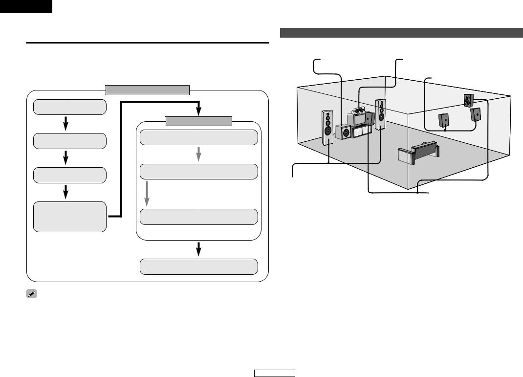
|
|
|
|
|
|
|
|
|
|
|
||||||||||||||||||||||
|
|
|
|
|
|
|
|
|
|
|
|
|
|
|
|
|
|
|
|
|
|
|
|
|
|
|
|
|
|
|
|
|
|
|
|
|
|
|||||||||
|
|
Enligt stadgarna i direktiv 73/23/EEC, 89/336/EEC och 93/68/EEC. |
|
|
|
|
|
|
|
|
|
|
|
|
|
|
|
|
I |
|
|
|
|
|
|
|
|
|
|
|
|
|
|
|
|
|
|
|
||||||||
|
|
|
|
|
|
|
|
|
|
|
|
|
|
|
|
|
|
|
|
|
|
|
|
|
|
|
|
|
|
|
|
|
|
|
|
|
|
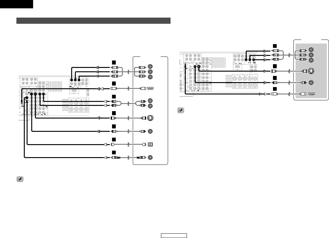
|||||||||
|
|
|
|
|
|
|
|
|
|
|
|
|
|
|
|
|
|
|
|
|
|
|
|
|
|
|
|
|
|
|
|
|
|
|
|
|
|
|
|
|
|
|
|
|
|
|
SVENSKA NEDERLANDS ESPAÑOL ITALIANO FRANCAIS DEUTSCH ENGLISH
A NOTE ABOUT RECYCLING:
This product’s packaging materials are recyclable and can be reused. Please dispose of any materials in accordance with the local recycling regulations.
When discarding the unit, comply with local rules or regulations.
Batteries should never be thrown away or incinerated but disposed of in accordance with the local regulations concerning chemical waste.
This product and the accessories packed together constitute the applicable product according to the WEEE directive except batteries.
HINWEIS ZUM RECYCLING:
Das Verpackungsmaterial dieses Produktes ist für zum Recyceln geeignet und kann wieder verwendet werden. Bitte entsorgen Sie alle Materialien entsprechend der örtlichen Recycling-Vorschriften.
Beachten Sie bei der Entsorgung des Gerätes die örtlichen Vorschriften und Bestimmungen.
Die Batterien dürfen nicht in den Hausmüll geworfen oder verbrannt werden; bitte geben Sie die Batterien gemäß örtlichen Bestimmungen an den Sammelstellen oder Sondermüllplätzen ab.
Dieses Produkt zusammen mit den Zubehörteilen ist das geltende Produkt der WEEE-Direktive, davon ausgenommen sind die Batterien.
UNE REMARQUE CONCERNANT LE RECYCLAGE:
Les matériaux d’emballage de ce produit sont recyclables et peuvent être réutilisés. Veuillez disposer de tout matériau conformément aux réglements de recylage locaux.
Lorsque vous mettez cet appareil au rebut, respectez les lois ou réglementations locales.
Les piles ne doivent jamais être jetées ou incinérées, mais mises au rebut conformément aux réglements locaux concernant les déchets chimiques.
Ce produit et les accessoires emballés ensemble sont des produits conformes à la directive DEEE sauf pour les piles.
NOTA RELATIVA AL RICICLAGGIO:
I materiali di imballaggio di questo prodotto sono riutilizzabili e riciclabili. Smaltire i materiali conformemente alle normative locali sul riciclaggio.
Per smaltire l’unità, osservare la normativa in vigore nel luogo di utilizzo.
Non gettare le batterie, né incenerirle, ma smaltirle conformemente alla normativa locale sui rifiuti chimici. Questo prodotto e gli accessori inclusi nell’imballaggio sono applicabili alla direttiva RAEE, ad eccezione delle batterie.
ACERCA DEL RECICLAJE:
Los materiales de embalaje de este producto son reciclables y se pueden volver a utilizar. Disponga de estos materiales siguiendo los reglamentos de reciclaje de su localidad.
Cuando se deshaga de la unidad, cumpla con las reglas o reglamentos locales.
Las pilas nunca deberán tirarse ni incinerarse. Deberá disponer de ellas siguiendo los reglamentos de su localidad relacionados con los desperdicios químicos.
Este producto junto con los accesorios empaquetados es el producto aplicable a la directiva RAEE excepto pilas.
EEN AANTEKENING WAT BETREFT HET RECYCLEREN:
Het inpakmateriaal van dit product is recycleerbaar en kan opnieuw gebruikt worden. Er wordt verzocht om zich van elk afvalmateriaal te ontdoen volgens de plaatselijke voorschriften.
Volg voor het wegdoen van de speler de voorschriften voor de verwijdering van witen bruingoed op.
Batterijen mogen nooit worden weggegooid of verbrand, maar moeten volgens de plaatselijke voorschriften betreffende chemisch afval worden verwijderd.
Op dit product en de meegeleverde accessoires, m.u.v. de batterijen is de richtlijn voor afgedankte elektrische en elektronische apparaten (WEEE) van toepassing.
EN KOMMENTAR OM ÅTERVINNING:
Produktens emballage är återvinningsbart och kan återanvändas. Kassera det enligt lokala återvinningsbestämmelser. När du kasserar enheten ska du göra det i överensstämmelse med lokala regler och bestämmelser.
Batterier får absolut inte kastas i soporna eller brännas. Kassera dem enligt lokala bestämmelser för kemiskt avfall. Denna apparat och de tillbehör som levereras med den är de som uppfyller gällande WEEE-direktiv, med undantag av batterierna.
CAUTION:
To completely disconnect this product from the mains, disconnect the plug from the wall socket outlet.
The mains plug is used to completely interrupt the power supply to the unit and must be within easy access by the user.
VORSICHT:
Um dieses Gerät vollständig von der Stromversorgung abzutrennen, trennen Sie bitte den Netzstecker von der Wandsteckdose ab.
Die Hauptstecker werden verwendet, um die Stromversorgung zum Gerät völlig zu unterbrechen; er muss für den Benutzer gut und einfach zu erreichen sein.
PRECAUTION:
Pour déconnecter complètement ce produit du courant secteur, débranchez la prise de la prise murale.
La prise secteur est utilisée pour couper complètement l’alimentation de l’appareil et l’utilisateur doit pouvoir y accéder facilement.
ATTENZIONE:
Per scollegare definitivamente questo prodotto dalla rete di alimentazione elettrica, togliere la spina dalla relativa presa.
La spina di rete viene utilizzata per interrompere completamente l’alimentazione all’unità e deve essere facilmente accessibile all’utente.
PRECAUCIÓN:
Para desconectar completamente este producto de la alimentación eléctrica, desconecte el enchufe del enchufe de la pared.
El enchufe de la alimentación se utiliza para interrumpir por completo el suministro de alimentación a la unidad y debe de encontrarse en un lugar al que el usuario tenga fácil acceso.
VOORZICHTIGHEID:
Om de voeding van dit product volledig te onderbreken moet de stekker uit het stopcontact worden getrokken.
De netstekker wordt gebruikt om de stroomtoevoer naar het toestel volledig te onderbreken en moet voor de gebruiker gemakkelijk bereikbaar zijn.
FÖRSIKTIHETSMÅTT:
Koppla loss stickproppen från eluttaget för att helt skilja produkten från nätet.
Stickproppen används för att helt bryta strömförsörjningen till apparaten, och den måste vara lättillgänglig för användaren.
II

ENGLISH
Thank you for choosing the DENON AVR-2307 AV Surround Receiver. This remarkable component has been engineered to provide superb surround sound listening with home theater sources such as DVD, as well as providing outstanding high fidelity reproduction of your favorite music sources.
As this product is provided with an immense array of features, we recommend that before you begin hookup and operation that you review the contents of this manual before proceeding.
Contents
Getting Started
Accessories······················································································2
Before using ····················································································3
Cautions on installation ·································································3
About the remote control unit ······················································3
Inserting the batteries····································································3
Operating range of the remote control unit ································3
Part names and functions
Front panel ·····················································································4
Display····························································································4 Rear panel ······················································································5
Remote control unit ···································································5, 6
Easy Setup Procedure
Easy to setup flow··········································································7
Speaker layout [Basic layout]························································7
Speaker connections ······································································8
Connecting a DVD player and monitor ········································9
Auto Setup/Room Equalizer (Room EQ) Functions
q Connecting a microphone ·······················································10
w Before performing the Auto Setup procedure ························11
e Perform the Auto Setup procedure·········································11 r Assigning power amplifiers ·····················································11
t Switching the front speaker ····················································11
y Starting Auto Setup ·································································12
u Checking and storing the measurement results ·····················12
Error messages ············································································13
Connecting Other Sources
Cable indications ··········································································14
The video conversion function····················································15
Relationship between the video input signal and
monitor output according to the video convert settings········15, 16
The analog video to HDMI conversion function························16
Connecting equipment with HDMI terminals
[To convert analog video signals to HDMI signals]···················17
Connecting a TV/DBS tuner ························································17
Connecting a video camera or video game ·······························17
Connecting a CD player ·································································18
Connecting a turntable ································································18
Connecting the external inputs (EXT. IN) terminals ·················18
Connecting equipment with HDMI terminals····························19
Connecting a DVD recorder·························································20
Connecting a VCR·········································································20
Connecting a tape deck, CD recorder or MD recorder··············21
Connecting the iPod® ··································································21
Connecting the antenna terminals ·············································22
Connecting the MULTI ZONE terminals
ZONE2 out connections ·······························································23
ZONE2 speaker out connections ·················································23
Connecting the RS-232C terminal···············································24
Connecting the PRE OUT terminals············································24
Connecting the power supply cord ············································24
Basic Operation
Playing the input source ······························································25
Turning the sound off temporarily (MUTING)·······························26 Listening over headphones ··························································26
Switching the front speakers ·······················································26
Checking the currently playing program source, etc. ··················26
Switching the brightness of the display·······································26
Using the surround modes
Types of surround modes and their features·························26, 27 Selecting the play mode (PURE DIRECT/DIRECT/STEREO)········27 Selecting the Dolby Digital and DTS Surround mode
(only with digital input) ·································································28
Selecting the Dolby Pro Logic IIx (Pro Logic II) mode·················29 Selecting the DTS NEO:6 mode ··················································30
Checking the input signals ···························································30
Surround modes and parameters········································31 ~ 33
Using the DENON original surround modes
Types of surround modes and their features·······························34 Selecting the DSP surround simulation ·······································35
Setting the tone control ·······························································36
Adjusting the speaker volume ·····················································36
Using the fader function ······························································36
Listening to the radio
Auto tuning···················································································37 Manual tuning ··············································································37
Preset memory ············································································38
Checking the preset stations ·······················································38
Recalling preset stations ······························································38
RDS (Radio Data System) ····························································38
RDS search ··················································································38
PTY search ···················································································39
TP search ·····················································································39
RT (Radio Text) ·············································································39
Advanced Operation
Night mode ···················································································40
User mode function
Storing the settings in the memory ·············································40
Calling the settings out ································································40
Combining the currently playing sound
with the desired image (VIDEO SELECT function)····················40
Personal memory plus function ··················································40
Playing the iPod® ·········································································40
Listening to music········································································41 Viewing still pictures and videos
(only for iPods equipped with the slideshow / video function)····41 Disconnecting the iPod ································································41
Multi zone music entertainment system ···································42
Outputting a program source to amplifier, etc.,
in the ZONE2 room (ZONE2 SELECT mode) ·······························43
Remote control unit operations during multi-source playback·····43 Recording (audio and/or video) ··················································44
About the memory functions ······················································44
Initialization of the microprocessor············································44
1
ENGLISH
Advanced Setup – Part 1
System setup items and default values ····························45 ~ 47
Navigating through the System Setup Menu ···························48
About the on screen display and front display ·························49
Audio Input Setup
Setting the Digital In Assignment ················································49
Setting the EXT. IN Subwoofer Level ··········································50
Setting the iPod Assignment ·······················································50
Setting the Input Function Level··················································50 Setting the Function Rename ······················································51
Setting the Tuner Presets ······················································51, 52
Video Setup
Setting the HDMI In Assignment·················································53 Setting the Component In Assignment ·······································53
Setting the Video Convert ····························································54
Setting the HDMI Out Setup ·······················································54
Setting the Audio Delay ·······························································55
Setting the On Screen Display (OSD) ··········································55
Advanced Playback
Setting the 2ch Direct/Stereo ················································55, 56 Setting the Dolby Digital Downmix Option Setup ·······················56
Setting the Auto Surround Mode·················································56 Setting the Manual Equalizer Setup·············································57
Option Setup
Setting the Power Amplifier Assignment ······························57, 58 Setting the Volume Control··························································58 Setting the Setup Lock ································································58
Advanced Setup – Part 2
Speaker Setup
Setting the Speaker Configuration ···············································59
Setting the Subwoofer Setup ······················································60
Setting the Distance·····································································60 Setting the Channel Level····························································61 Setting the Crossover Frequency ················································62
Others Setup
Setting the Room Equalizer Setup ···············································62
Setting the Direct Mode Setup ····················································63
Check the parameter····································································63
Operating the remote control unit
Operating DENON audio components ·······································64
Setting the preset memory function ··········································64
Operating a component stored in the preset memory····65 ~ 67
Setting the punch through function···········································68
Additional Information···························································69, 70
Troubleshooting······································································71, 72
Specifications ················································································72
List of preset codes ············································End of this manual
ENGLISH
Getting Started
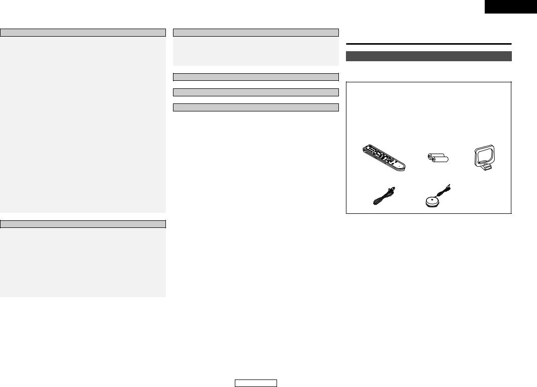
Accessories
Check that the following parts are attached in addition to the main unit:
q Operating instructions .............................................................. |
|
1 |
w Service station list .................................................................... |
|
1 |
e Remote control unit (RC-1044)................................................. |
|
1 |
r R6P/AA batteries ...................................................................... |
|
2 |
t AM loop antenna ...................................................................... |
|
1 |
y FM indoor antenna ................................................................... |
|
1 |
u Setup microphone (DM-S205) (Approx. 6 m) |
...........................1 |
|
e |
r |
t |
y |
u |
2
ENGLISH

ENGLISH
Getting Started
Before using
Pay attention to the following before using this unit:
•Moving the unit.
To prevent short-circuits or damaged wires in the connection cables, always unplug the power supply cord and disconnect the connection cables between all other audio components when moving the unit.
•Cautions on using mobile phones.
Using a mobile phone near this unit may result in noise. If so, move the mobile phone away from this unit when it is in use.
•Before turning the power operation button on.
Check once again that all connections are correct and that there are not problems with the connection cables. Always set the power operation button to the standby position before connecting and disconnecting connection cables.
•Store the operating instructions in a safe place.
After reading the operating instructions, store them in a safe place as they could come in handy in the future.
•Whenever the power operation button is in the STANDBY state, the unit is still connected to AC line voltage.
Please be sure to turn off the power switch or unplug the cord when you leave home for, say, a vacation.
•Note that the illustrations in these instructions may differ from the actual unit for explanation purposes.
Cautions on installation
Note:
For heat dispersal, do not install this unit in a confined space such as a bookcase or similar enclosure.
Note |
Wall |
About the remote control unit
In addition to controlling the AVR-2307, the attached remote control unit (RC-1044) can also be used to control the following products:
q DENON component products
wComponent products other than DENON:
• Set using the preset memory function (  page 64).
Inserting the batteries
q Remove the remote control |
w Set two R6P/AA batteries in |
unit’s rear cover. |
the battery compartment in |
|
the indicated direction. |
e Put the rear cover back on.
Notes on batteries:
•Replace the batteries with new ones if the set does not operate even when the remote control unit is operated nearby the unit. (The attached batteries are only for verifying operation.)
•When inserting the batteries, be sure to do so in the proper direction, following the “<” and “>” marks in the battery compartment.
•To prevent damage or leakage of battery fluid:
•Do not use a new battery together with an old one.
•Do not use two different types of batteries.
•Do not short-circuit, disassemble, heat or dispose of batteries in flames.
•Remove the batteries from the remote if it will not be in use for long periods.
•If the battery fluid should leak, carefully wipe the fluid off the inside of the battery compartment and insert new batteries.
•When replacing the batteries, have the new batteries ready and insert them as quickly as possible.
3
Getting Started
Operating range of the remote control unit
•Point the remote control unit at the remote sensor when operating it.
•The remote control unit can be used from a distance of approximately 7 meters, at a horizontal angle of up to 30° with respect to the sensor.


 30° 30°

Approx. 7 m
NOTE:
•It may be difficult to operate the remote control unit if the remote sensor is exposed to direct sunlight or strong artificial light.
ENGLISH

Getting Started
Part names and functions
For details on the functions of these parts, refer to the pages given in parentheses ( ).
Front panel
@0 !8
@9@8 @7@6@5@4@3 @2 |
@1 |
!9 |
!7 |
|||||||||||||||||||||||||||||||
|
|
|
|
|
|
|
|
|
|
|
|
|
|
|
|
|
|
|
|
|
|
|
|
|
|
|
|
|
|
|
|
|
|
|
|
|
|
|
|
|
|
|
|
|
|
|
|
|
|
|
|
|
|
|
|
|
|
|
|
|
|
|
|
|
|
|
|
|
|
|
|
|
|
|
|
|
|
|
|
|
|
|
|
|
|
|
|
|
|
|
|
|
|
|
|
|
|
|
|
|
|
|
|
|
|
|
|
|
|
|
|
|
|
|
|
|
|
|
|
|
|
|
|
|
|
|
|
|
|
|
|
|
|
|
|
|
|
|
|
|
|
|
|
|
|
|
|
|
|
|
|
|
|
|
|
|
|
|
|
|
|
|
|
|
|
|
|
|
|
|
|
|
|
|
|
|
|
|
|
|
|
|
|
|
|
|
|
|
|
|
|
|
|
|
|
|
|
|
|
|
|
|
|
|
|
|
|
|
|
|
|
|
|
|
|
|
|
|
|
|
|
|
|
|
|
|
|
|
|
|
|
|
|
|
|
|
|
|
|
|
|
|
|
|
|
|
|
|
|
|
|
|
|
|
|
|
|
|
|
|
|
|
|
|
|
|
|
|
|
|
|
|
|
|
|
|
|
|
|
|
|
|
|
|
|
|
|
|
|
|
|
|
|
|
|
|
|
|
|
|
|
|
|
|
|
|
|
|
|
|
|
|
|
|
|
|
|
|
|
|
|
|
|
|
|
|
|
|
|
|
|
|
|
|
|
|
|
|
|
|
|
|
|
|
|
|
|
|
|
t |
|
!3 |
q w e r y u i o !0 |
!1 |
!2!4!5!6 |
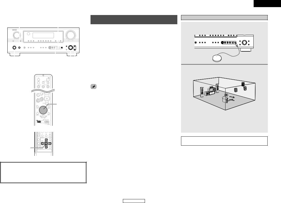
q Power operation button
(ON/STANDBY) ··········································(11)
w Power indicator ·········································(11)
e Power switch ·······································(11, 44) r Headphones jack (PHONES) ·····················(26)
t ANALOG button ········································(25)
y SPEAKER buttons ······································(26)
u ZONE2 button ············································(42)
i SHIFT button ··············································(38)
o USER MODE buttons ································(40)
!0PRESET buttons·········································(37)
!1V. AUX INPUT terminals
Remove the cap covering the terminals when you want to use them.
!2SETUP MIC jack ·········································(10)
!3SYSTEM SETUP button ····························(11)
!4SURR. MODE/SURR. PARA button····(25, 35)
!5SELECT/ENTER knob ··························(11, 35)
SELECT/ENTER knob on the main unit operates same way as the CURSOR F and G buttons remote control unit.
•The control functions in the same way as the CURSOR F button when turned counterclockwise, as the CURSOR G button when turned clockwise.
•The control functions in the same way as the ENTER button when pressed the knob.
!6Cursor buttons (D, H) ·······························(11)
!7MASTER VOLUME control knob··············(25)
!8TUNING buttons (•, ª) ·····························(37)
!9RT button····················································(38)
@0PTY button ·················································(38)
@1RDS button·················································(38)
@2Display
ENGLISH
Getting Started
@3BAND button··············································(37)
@4EXT. IN button············································(25)
@5Remote control sensor································(3)
@6INPUT MODE button ·································(25)
@7ZONE2/REC SELECT button ·····················(43)
@8FUNCTION knob ········································(25)
@9MAIN button ··············································(25)
Display |
|
|
|
|
!3!2!1!0 |
o |
i |
u |
y |
q w |
|
e |
r |
t |
q Input signal indicators
w Input signal channel indicators
•The audio channel(s) included in the input signal light(s).
•This lights when the digital signal is inputted.
e Information display
r Output signal channel indicators
The audio channels that can be output light.
t Speaker indicators
This lights corresponding to the settings of the front speakers of the various surround modes.
y ZONE2 output indicator
u Master volume indicator
This displays the volume level.
The Setup item number is displayed in System Setup.
i ZONE2/REC SELECT indicators
Lights while selecting the ZONE2 or REC
SELECT mode. (Off when the “SOURCE” is selected.)
o Input mode indicators
!0RDS indicator
This lights when an RDS broadcast has been received.
!1AUTO indicator
This lights when the broadcast station is selected in the AUTO tuning mode.
!2STEREO indicator
This lights when an FM stereo broadcast has been received.
!3TUNED indicator
This lights when an FM/AM broadcast has been received.
4
ENGLISH

ENGLISH
Getting Started |
Getting Started |
|
|
|
|
Rear panel |
|
Remote control unit |
!3!2!1 !0 |
!4 !5q w e |
e |
q DIGITAL terminals
(Optical/Coaxial) ·············································(9)
w VIDEO/S-VIDEO terminals··························(9)
e AUDIO terminals··········································(9)
r Speaker terminals ·······································(8)
t AC outlet ····················································(24)
y Power supply cord·····································(24)
u PRE OUT terminals····································(24)
i COMPONENT VIDEO terminals··················(9)
o |
i |
u |
y t |
|
|
r |
|
o RS-232C terminal·······································(24) |
|||
!0EXT. IN terminals·······································(18)
!1DOCK CONTROL jack ································(21)
!2ANTENNA terminals ·································(22)
!3HDMI terminals··········································(19)
!4SIGNAL GND terminal ······························(18)
!5REMOTE CONTROL jacks ·························(23)
Indicator ··························(64)
Function buttons············(25)
System buttons ·····(65 ~ 67)
VIDEO SELECT/SETUP button························(40, 65)
Cursor buttons
(D, H, F, G) ····················(11)
ON SCREEN/DISPLAY button························(26, 65)
DIMMER/MENU button························(26, 65)
[ Front ]
Remote control signal transmitter ························(3)
Power buttons················(11)
Tuner system/System buttons······················(37, 66)
USER MODE buttons ·····(40)
Master volume control buttons ····························(25)
MUTING button··············(26)
NIGHT/AUDIO button························(40, 65)
CH SELECT/ENTER button························(11, 36)
STATUS/RETURN button························(26, 65)
Mode selector
switches ····················(11, 64)
NOTE:
•If buttons on the front or rear are pressed strongly, the button on the opposite side will be activated too.
5
ENGLISH

ENGLISH
Getting Started |
Getting Started |
[ Rear ]
ZONE2 buttons···············(43)
Function / Number buttons······················(25, 65)
Tuner system/System buttons······················(37, 65)
TEST TONE/DISPLAY button························(61, 65)
Cursor buttons
(D, H, F, G) ····················(11)
MAIN buttons ·················(43)
SURROUND MODE buttons ····························(27)
SYSTEM SETUP/SETUP button························(11, 65)
SURROUND PARAMETER/ AUDIO button···········(25, 65)
ENTER button·················(11)
INPUT MODE/RETURN button························(25, 65)
NOTE:
•If buttons on the front or rear are pressed strongly, the button on the opposite side will be activated too.
6
ENGLISH
ENGLISH
Easy Setup Procedure
•This section contains the basic steps necessary to configure the AVR-2307 according to your listening room environment and the source equipment and loudspeakers you are using.
•To set the sound field manually (  page 59 ~ 62).
Placing the speakers.
Connecting the speakers.
Connect the DVD player to the AVR-2307.
Connect the AVR-2307’s monitor output terminal to the TV’s video input terminal (  page 9).
Easy to setup flow
Auto setup flow
Connecting a microphone (  page 10).
The measurement of the speakers in the listening position.
Check of the measurement result.
Play a DVD.
Easy Setup Procedure
Speaker layout [Basic layout]
Example of basic layout with eight speakers and a monitor.
Subwoofer |
Center speaker |
Surround back speaker
Front speaker |
|
|
Set these at the sides of the |
|
|
monitor or screen with their front |
|
Surround speaker |
surfaces as flush with the front of |
|
|
the screen as possible. |
|
|
not plug in the power supply cord until all connections have been completed.
7
ENGLISH
Easy Setup Procedure
Speaker connections
Connect the speaker terminals with the speakers making sure that like polarities are matched (< with <, > with >).
NOTE:
When making connections, take care that none of the individual conductors of the speaker cable come in contact with adjacent terminals, with other speaker cable conductors, or with the rear panel and screws.
NEVER touch the speaker terminals when the power is on. Doing so could result in electric shocks.
Connecting the speaker cables
1. Loosen by turning counterclockwise.
Either tightly twist or terminate the core wires.
2. Insert the cable.
3. Tighten by turning clockwise.
¢ Speaker impedance
Speaker |
Impedance |
Front A, B |
6 ~ 16 Ω/ohms |
|
|
Front A+B |
12 ~ 16 Ω/ohms |
|
|
Center |
|
|
|
Surround |
6 ~ 16 Ω/ohms |
|
|
Surround back / ZONE2 |
|
|
|
Note on speaker impedance
When using speakers with an impedance below the designated value (for example 4 Ω/ohms), playing for long periods of time with the volume high could cause the temperature to rise, activating the protection circuit.
When the protection circuit is activated, the output to the speakers is cut off and the power indicator blinks. If this happens, unplug the power supply cord, wait for the set to cool off and improve ventilation around the unit. Also check the wiring of the input cables and the speaker cables. After doing this, plug the power supply cord back in and turn the unit’s power back on.
If the protection circuit is activated again even though there are no problems with the wiring or the ventilation around the unit, switch off the power and contact a DENON service center.
ENGLISH
Easy Setup Procedure
¢ Connections
•With the AVR-2307, up to ten speakers can be connected for surround playback.
•When making connections, also refer to the operating instructions of the other components.
Center |
|
Surround |
|
speaker |
Subwoofer |
speakers |
|
|
Connection terminal for |
|
|
|
subwoofer with built-in |
|
|
|
amplifier. |
|
|
|
|
(L) |
(R) |
|
IN |
|
|
> < |
> |
< > |
< |
|
|
|
|
(L) |
(R) |
(L) |
(R) |
< > |
> < |
< > |
> < |
Front speakers |
|
Front speakers |
(B) |
|
(A) |
|
|
|
(L) (R)
> < >
< > <
<
Surround back speakers
When using only one surround back speaker, connect it to the left channel.
8
ENGLISH
ENGLISH
Easy Setup Procedure
Connecting a DVD player and monitor
• To connect the video output from the DVD player to the AVR-2307, you only need to choose one connection type. For more information about the video up conversion function (  page 15).
•To connect the digital audio output from the DVD player, you can choose from either the coaxial or optical connections. If you choose to use the coaxial connection, it needs to be assigned. For more information about Digital Input Assignment (  page 49).
|
DVD player |
|
H |
COMPONENT VIDEO OUT |
|
|
|
Y |
|
|
PB |
|
|
PR |
I |
|
|
|
|
HDMI |
|
|
OUT |
A |
|
AUDIO OUT |
L |
L |
L |
|
||
R |
R |
R |
G |
|
|
|
|
S VIDEO |
|
|
OUT |
F |
|
|
|
|
VIDEO |
|
|
OUT |
D |
|
|
|
|
OPTICAL |
|
|
OUT |
C |
|
|
|
|
COAXIAL |
|
|
OUT |

 Audio signal flow is shown with white arrows, video signal flow is shown with gray arrows.
a non-DVD video disc player (such as a laser disc, VCD/SVCD, or future high definition disc to the DVD/VDP terminals in the same way.
Easy Setup Procedure
•For best picture quality (especially with progressive DVD and other high definition sources), choose the component video or HDMI connection to your monitor. S-Video and composite video outputs are also provided if your monitor does not have component video inputs.
|
Monitor |
H |
COMPONENT VIDEO IN |
|
|
|
Y |
|
PB |
|
PR |
G |
|
|
S VIDEO |
|
IN |
F |
VIDEO |
|
|
|
IN |
I |
|
|
HDMI |
|
IN |
AVR-2307 is equipped with HDMI terminals, so it can be connected to a DVD player or monitor an HDMI cable.
component video input and/or output terminals may be labelled differently on some monitors or components. Check the owner’s manuals for other components for further information.
signals are only output from the HDMI monitor out terminal when audio signals are input to the input terminal.
connecting the AVR-2307 and DVD player using an HDMI cable, also connect the AVR-2307 and using an HDMI cable (  page 19).
9
ENGLISH
Easy Setup Procedure
<POWER> |
SYSTEM SETUP |
|
|
|
|
|
|
|
|
|
|
|
|
|
|
|
|
|
|
|
|
|
|
|
|
|
|
|
|
|
|
|
|
|
|
|
|
|
|
|
|
|
|
|
|
|
|
|
|
|
|
|
|
|
|
|
|
|
|
|
|
|
|
|
|
|
|
|
|
|
|
|
|
|
|
|
|
|
|
|
|
|
|
|
|
|
|
|
|
|
|
<ON/STANDBY> |
<SETUP MIC> |
D H |
||||||||||||
F G, ENTER

 [ON/SOURCE]
ENTER

 D H F G
[MODE SELECTOR 1] 
SYSTEM SETUP 
D H F G 


ENTER
About the button names in this explanation
<> : Buttons on the main unit
[ |
] : Buttons on the remote control unit |
Button name only :
Buttons on the main unit and remote control unit
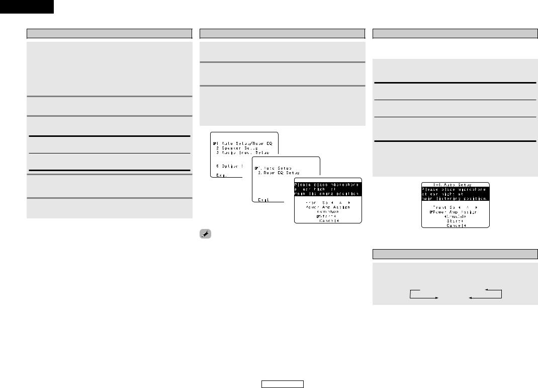
Auto Setup/Room Equalizer (Room EQ)
Functions
•The AVR-2307’s auto setup and room equalizer functions use the attached microphone to measure the acoustic properties in the room and automatically make the optimum settings.
•When the auto setup procedure is performed, one of the following three correction curves can be selected for the room equalizer function.
Normal:
Adjust the frequency response of all speaker suitable for general surround system.
Front:
This adjusts the characteristics of each speaker to the characteristics of the front speakers.
Flat:
This the frequency response of all speakers flat. This mode is optimum for playing multi-channel signal music.
the sound field settings manually (  page 59 ~ 62).
ENGLISH
Easy Setup Procedure
qConnecting a microphone
1Connect the attached setup microphone to <SETUP MIC>.
Sound receptor 

2 Mount the setup microphone on a camera tripod, etc., and set with the receptor pointing towards the ceiling.
Microphone


 Place the setup microphone’s sound receptor at the height of the ears in the listening position.

 It is not possible to measure properly if there are any obstacles between the speakers and microphone. Check that there are no obstacles.
NOTE:
• Once the settings are completed, disconnect the setup microphone.
10
ENGLISH
ENGLISH
Easy Setup Procedure
w Before performing the Auto Setup procedure
1 Turn on your subwoofer.

 Set the volume to halfway and set the crossover frequency to the maximum or Low pass filter off if your subwoofer can adjust the output volume and the crossover frequency.

 Some subwoofers have a standby mode. Be sure to turn this function off before performing the Auto Setup procedure.
2 Turn on your monitor.
3 Press <POWER>.
¢ ON:
The power indicator lights red.
£ OFF:
The power turns off and the indicator is off.
4 Press <ON/STANDBY> or [ON/SOURCE].
• The power indicator blinks green and the power turns on.
5 Set [MODE SELECTOR 1] to “AUDIO”.
e Perform the Auto Setup procedure
1 Press SYSTEM SETUP.
2 Press D H to select “Auto Setup / Room EQ”, then press ENTER.
3 Press D H to select “Auto Setup”, then press ENTER.

 The message “Connect Microphone” is displayed if no microphone is connected. If so, connect the auto setup microphone.
1


 2
2 


 3
3


Setup Menu” is not displayed when using headphones.
Easy Setup Procedure
r Assigning power amplifiers
The surround back output can be assigned to the “Front” or “ZONE2” output.
Press D H to select “Power Amp Assign”, then press F G to set.
Surround Back:
Assign to use as surround back speaker.
ZONE2:
Assign to use as “ZONE2” speakers.
Front A, Front B:
Assign to use the “Front A” or “Front B” speakers with bi-amp connections.

 When assigned to “Front” or “ZONE2”, skip the surround back channel measurement.

 During the auto setup procedure, test tones are not output to “ZONE2”.
t Switching the front speaker
Press D H to select “Front Sp”, then press F G to select the speaker.
 Front A
 Front B
Front A+B
11
ENGLISH

Easy Setup Procedure
y Starting Auto Setup
Press D H to select “Start”, then press F.
• Start the measurements.

 Measurement of each channel is performed as follows:
1 |
2 |
FL FR C SW SL |
SR SBL SBR |

 1: The subwoofer speaker is measured twice.

 2: Not displayed when “ZONE2” and “Front” are set at “Setting the
Power Amplifier Assignment” ( |
page 57, 58). |
•After each channel is measured, “Calculating” appears.
•The display switches to the Auto Setup check screen automatically.
e
NOTE:
•Do not change the speaker connections or subwoofer volume after making the measurements.
•Do not turn off the power while the data is being stored.
Cautions during measurements:
•Loud test tones are output during the measurements. Be careful for example when small children are nearby.
•Proper measurements may not be possible if there are obstacles between the speaker and the setup microphone.
•During the measurements, do not stand between or near the speakers and setup microphone.
•To avoid influencing the measurements, turn off the power of airconditioners or any other equipment producing sound in the room. Perform the measurements with the room as quiet as possible.
•Measurement is cancelled when VOLUME is operated while the Auto Setup is performed.
¢ About automatic retry
To confirm the results of the measurements, remeasurement is automatically performed.
Remeasurement is performed up to two times. During this time, “Retry1” or “Retry2” is displayed on the screen.
ENGLISH
Easy Setup Procedure
u Checking and storing the measurement results
1 Press D H to select an item, then press ENTER.

 The measurement results of each item can be checked here.
2 After checking, press ENTER, then press D H to set.
Store:
All the settings are stored in the memory.
Retry:
Perform the measurement again.
Measurement is repeated.
Cancel:
Cancel the auto setup settings.
3 When “Store” is selected: Press F.
1
h (Press ENTER.)
2
Example: Speaker Configuration Check
measurements have been made using the measurement speakers with a built-in filter such as subwoofers might with a value that differs from the physical distance because
internal electrical delay.
12
ENGLISH
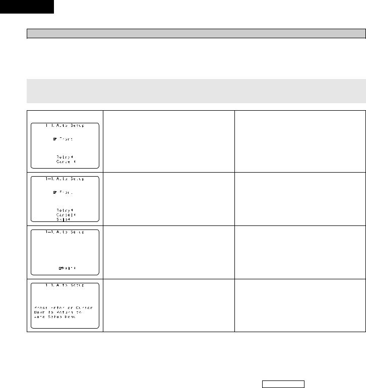
ENGLISH
Easy Setup Procedure
Error messages
•These error screens may be displayed when performing Auto Setup measurement and the automatic measurements can not be completed because of the speaker arrangement, measurement environment, or other factors. Please check the following matters, reset the pertinent items, and measure again.
•When there is too much noise in the room, the speakers may not be detected properly. Should this happen, perform the measurements when the noise level is low, or switch off the power of the equipment that is producing the noise for the duration of the measurements.
Press D H to select the items, then press F.
|
|
|
Example |
Cause |
Measures |
|
|
|
|
q This screen will be displayed when the speakers required |
• Check that the pertinent speakers are properly connected. |
|
|
|
|
for producing suitable reproduction have not been detected. |
|
|
|
|
|
|
|
|
|
w This screen will be displayed when the speaker polarity is |
• Check the polarity of the pertinent speakers. For some |
|
|
|
||
|
|
|
||
|
|
|
||
|
|
|
connected in reverse. |
speakers, this screen may be displayed even though the |
|
|
|
||
|
|
|
|
speakers are properly connected. |
|
|
|
|
If so, select “Skip0”. |
|
|
|
|
|
|
|
|
|
|
|
e This screen will be displayed when accurate measurements |
• Set up the speakers so that their position is farther away |
|
cannot be made due to the input level of the microphone being |
from the listening position. |
|
||
|
too high. |
• Lower the volume of the subwoofer speaker. |
|
|
|
|
|
|
|
|
|
|
|
r This screen will be displayed when the measurement |
• Connect the measurement microphone to the microphone |
|
|
|
|
|
microphone is not connected. |
connector. |
|
|
|
|
|
||
|
|
|
|
|
|
|
|
|
|
|
|
|
|
13
Easy Setup Procedure
ENGLISH

ENGLISH
Connecting Other Sources
Cable indications
The hookup diagrams on the subsequent pages assume the use of the following optional connection cables (not supplied).
|
|
Audio cable |
|
|
Video cable |
|
|
A |
Analog connections (Stereo) |
F |
Video connections |
|
|
|
|
|
(White) |
L |
L |
(Yellow) |
|
|
|
|
(Red) |
R |
R |
Video cable (75 Ω/ohms video pin-plug cable) |
|||
|
|
|
|
||||
|
|
Pin-plug cable |
G |
S-Video connections |
|
|
|
B |
|
|
|
|
|||
Analog connections (Monaural, for subwoofer) |
|
|
|
|
|||
|
|
|
|
|
S-Video cable |
|
|
|
|
Pin-plug cable |
H |
Component video connections |
|
|
|
|
|
|
|
|
|||
C |
Digital connections (Coaxial) |
|
(Green) |
|
|
(Y) |
|
|
|
|
|
|
|
||
|
(Orange) |
|
|
(Blue) |
|
|
(PB/CB) |
|
|
|
|
|
|
|
|
|
|
Coaxial cable (75 Ω/ohms pin-plug cable) |
(Red) |
|
|
(PR/CR) |
|
|
|
Component video cable |
|
||||
|
|
|
|
|
|||
D |
Digital connections (Optical) |
|
Audio and Video cable |
|
|||
|
|
|
|
|
|||
|
|
|
I |
HDMI connections |
|
|
|
|
|
Optical fiber cable |
|
|
|
|
|
E |
Speaker connections |
|
|
19-pin HDMI cable |
|
|
|
|
|
|
|
|
|
|
|
|
|
|
|
|
Signal direction |
|
|
|
|
Speaker cable |
|
Audio signal |
|
|
|
|
|
|
IN |
OUT |
OUT |
IN |
|
|
|
|
|
||||
|
|
|
|
Video signal |
|
|
|
NOTE:
•Do not plug in the power supply cord until all connections have been completed.
•When making connections, also refer to the operating instructions of the other components.
•Be sure to connect the left and right channels properly (left with left, right with right).
•Do not bundle power supply cords together with speaker cables. Doing so could result in humming or noise.
IN |
OUT |
OUT |
IN |
14
ENGLISH

ENGLISH
Connecting Other Sources
The video conversion function
•Even if the formats of the video signals from the various players differ, the different formats can be converted and the signals output to the monitor from a single video output terminal. We recommend outputting with the format offering the highest quality video signals possible.
•With analog video signal connections, generally quality is higher in the order shown below.
The flow of the video signals.
(HDMI terminal) |
(HDMI |
|
terminal) |
(Component |
(Component |
Video terminals) |
Video terminals) |
(S-Video terminal) |
(S-Video terminal) |
(Video terminal) |
(Video terminal) |
AVR-2307’s input |
AVR-2307’s output |
terminals |
terminals |
|
: only 480i/576i |
Connecting Other Sources
Relationship between the video input signal and monitor output according to the video convert settings
Video convert |
|
|
Input signals |
|
|
|
|
|
|
MONITOR OUT |
|
|
||||
HDMI |
|
COMPONENT |
S-VIDEO |
VIDEO |
|
HDMI |
|
COMPONENT |
S-VIDEO |
|
VIDEO |
|||||
|
|
|
|
|
|
|||||||||||
|
|
E |
|
E |
E |
E |
|
|
E |
|
E |
|
E |
|
E |
|
|
|
E |
|
E |
E |
C |
|
VIDEO |
|
VIDEO |
|
VIDEO |
|
VIDEO |
||
|
|
E |
|
E |
C |
E |
|
S-VIDEO |
|
S-VIDEO |
|
S-VIDEO |
|
S-VIDEO |
||
|
|
E |
|
E |
C |
C |
|
S-VIDEO |
|
S-VIDEO |
|
S-VIDEO |
|
S-VIDEO |
||
|
|
E |
|
C (1080p) |
E |
E |
|
|
E |
|
COMPONENT |
E |
|
E |
||
|
|
E |
|
C (480p ~ 720p) |
E |
E |
|
COMPONENT |
COMPONENT |
E |
|
E |
||||
|
|
E |
|
C (480i/576i) |
E |
E |
|
COMPONENT |
COMPONENT |
COMPONENT |
COMPONENT |
|||||
|
|
E |
|
C (1080p) |
E |
C |
|
VIDEO |
|
COMPONENT |
1 |
VIDEO |
|
VIDEO |
||
|
|
E |
|
C (480p ~ 720p) |
E |
C |
COMPONENT |
1 |
COMPONENT |
1 |
E |
3 |
VIDEO |
|||
|
|
E |
|
C (480i/576i) |
E |
C |
COMPONENT |
1 |
COMPONENT |
1 |
COMPONENT |
VIDEO |
||||
|
|
E |
|
C (1080p) |
C |
E |
|
S-VIDEO |
|
COMPONENT |
2 |
S-VIDEO |
|
S-VIDEO |
||
|
|
E |
|
C (480p ~ 720p) |
C |
E |
COMPONENT |
2 |
COMPONENT |
2 |
S-VIDEO |
|
S-VIDEO |
|||
|
|
E |
|
C (480i/576i) |
C |
E |
COMPONENT |
2 |
COMPONENT |
2 |
S-VIDEO |
|
S-VIDEO |
|||
|
|
E |
|
C (1080p) |
C |
C |
|
S-VIDEO |
|
COMPONENT |
2 |
S-VIDEO |
|
S-VIDEO |
||
ON |
|
E |
|
C (480p ~ 720p) |
C |
C |
COMPONENT |
2 |
COMPONENT |
2 |
S-VIDEO |
|
S-VIDEO |
|||
|
|
E |
|
C (480i/576i) |
C |
C |
COMPONENT |
2 |
COMPONENT |
2 |
S-VIDEO |
|
S-VIDEO |
|||
|
|
C |
|
E |
E |
E |
|
HDMI |
|
E |
|
E |
|
E |
||
|
|
C |
|
E |
E |
C |
|
HDMI |
1 |
VIDEO |
|
VIDEO |
|
VIDEO |
||
|
|
C |
|
E |
C |
E |
|
HDMI |
2 |
S-VIDEO |
|
S-VIDEO |
|
S-VIDEO |
||
|
|
C |
|
E |
C |
C |
|
HDMI |
2 |
S-VIDEO |
|
S-VIDEO |
|
S-VIDEO |
||
|
|
C |
|
C (Other than 480i/576i) |
E |
E |
|
HDMI |
|
COMPONENT |
E |
|
E |
|||
|
|
C |
|
C (480i/576i) |
E |
E |
|
HDMI |
|
COMPONENT |
COMPONENT |
COMPONENT |
||||
|
|
C |
|
C (1080p) |
E |
C |
|
HDMI |
1 |
COMPONENT |
1 |
VIDEO |
|
VIDEO |
||
|
|
C |
|
C (480p ~ 720p) |
E |
C |
|
HDMI |
1 |
COMPONENT |
1 |
E |
3 |
VIDEO |
||
|
|
C |
|
C (480i/576i) |
E |
C |
|
HDMI |
1 |
COMPONENT |
1 |
COMPONENT |
VIDEO |
|||
|
|
C |
|
C (Other than 480i/576i) |
C |
E |
|
HDMI |
2 |
COMPONENT |
2 |
S-VIDEO |
|
S-VIDEO |
||
|
|
C |
|
C (480i/576i) |
C |
E |
|
HDMI |
2 |
COMPONENT |
2 |
S-VIDEO |
|
S-VIDEO |
||
|
|
C |
|
C (Other than 480i/576i) |
C |
C |
|
HDMI |
2 |
COMPONENT |
2 |
S-VIDEO |
|
S-VIDEO |
||
|
|
C |
|
C (480i/576i) |
C |
C |
|
HDMI |
2 |
COMPONENT |
2 |
S-VIDEO |
|
S-VIDEO |
||
|
|
C : Signal input |
|
|
|
E |
: Not output |
|
|
|
|
|||||
|
|
|
|
|
|
|
|
|
||||||||
|
|
E : No signal |
|
|
|
1 |
: On screen display superimposed on video signal and |
|||||||||
|
|
480p ~ 720p : 480p/576p/1080i/720p |
|
|
|
|
|
|
output. |
|
|
|
|
|||
|
|
|
|
|
|
|
2 |
: On screen display superimposed on S-Video signal and |
||||||||
|
|
|
|
|
|
|
|
|
|
|
output. |
|
|
|
|
|
|
|
|
|
|
|
|
3 |
: Video signals are output when the “Analog to HDMI |
||||||||
video conversion function is compatible with the following format: NTSC, |
|
|
|
|
convert” is set to “OFF”. |
|
|
|||||||||
COMPONENT : On screen display only displayed for SYSTEM SETUP, |
||||||||||||||||
SECAM, NTSC4.43, PAL-N, PAL-M and PAL-60. |
|
|
||||||||||||||
|
|
|
|
|
|
SURROUND PARAMETER and ON SCREEN buttons. |
||||||||||
SECAM signals of video input are up-converted, the signals are output |
|
|
|
|
||||||||||||
HDMI |
: The on screen display is displayed when the “Analog to |
|||||||||||||||
|
format from the S-Video terminal. |
|
|
|||||||||||||
|
|
|
|
|
|
|
HDMI convert” is set to “ON”. |
|
|
|||||||
|
up-converted to HDMI are output to the HDMI monitor with the |
|
|
|
|
|
|
|||||||||
|
|
|
|
: Video signals are not output when the “Analog to HDMI |
||||||||||||
|
at which they are input. Note that resolutions of 1080p are not |
|
|
|
||||||||||||
|
|
|
|
|
convert” is set to “OFF”. |
|
|
|||||||||
|
. |
|
|
|
|
|
|
|
|
|
|
|
||||
|
|
|
|
|
|
|
|
|
|
|
|
|
|
|
||
15
ENGLISH
Connecting Other Sources
Video convert |
S-VIDEO |
|
|
Input signals |
|
|
|
MONITOR OUT |
|
|
||
MONITOR OUT |
HDMI |
|
COMPONENT |
S-VIDEO |
VIDEO |
HDMI |
COMPONENT |
S-VIDEO |
VIDEO |
|
||
|
|
|
||||||||||
|
– |
E |
|
E |
E |
E |
E |
E |
|
E |
E |
|
|
– |
E |
|
E |
E |
C |
E |
E |
|
E |
VIDEO |
|
|
– |
E |
|
E |
C |
E |
E |
E |
|
S-VIDEO |
E |
|
|
Used |
E |
|
E |
C |
C |
E |
E |
|
S-VIDEO |
VIDEO |
2 |
|
Not used |
E |
|
E |
C |
C |
E |
E |
|
– |
VIDEO |
|
|
– |
E |
|
C |
E |
E |
E |
COMPONENT |
E |
E |
|
|
|
– |
E |
|
C |
E |
C |
E |
COMPONENT |
1 |
E |
VIDEO |
|
|
– |
E |
|
C |
C |
E |
E |
COMPONENT |
2 |
S-VIDEO |
E |
|
|
Used |
E |
|
C |
C |
C |
E |
COMPONENT |
2 |
S-VIDEO |
VIDEO |
2 |
OFF |
Not used |
E |
|
C |
C |
C |
E |
COMPONENT |
1 |
– |
VIDEO |
|
– |
C |
|
E |
E |
E |
HDMI |
E |
|
E |
E |
|
|
|
|
|
|
|||||||||
|
– |
C |
|
E |
E |
C |
HDMI |
E |
|
E |
VIDEO |
|
|
– |
C |
|
E |
C |
E |
HDMI |
E |
|
S-VIDEO |
E |
|
|
Used |
C |
|
E |
C |
C |
HDMI |
E |
|
S-VIDEO |
VIDEO |
2 |
|
Not used |
C |
|
E |
C |
C |
HDMI |
E |
|
– |
VIDEO |
|
|
– |
C |
|
C |
E |
E |
HDMI |
COMPONENT |
E |
E |
|
|
|
– |
C |
|
C |
E |
C |
HDMI |
COMPONENT |
1 |
E |
VIDEO |
|
|
– |
C |
|
C |
C |
E |
HDMI |
COMPONENT |
2 |
S-VIDEO |
E |
|
|
Used |
C |
|
C |
C |
C |
HDMI |
COMPONENT |
2 |
S-VIDEO |
VIDEO |
2 |
|
Not used |
C |
|
C |
C |
C |
HDMI |
COMPONENT |
1 |
– |
VIDEO |
|
|
|
C : Signal input |
|
|
E |
: Not output |
|
|
|
|||
|
|
|
|
|
|
|
||||||
|
|
E : No signal |
|
|
|
1 |
: On screen display superimposed on video signal and |
|||||
|
|
|
|
|
|
|
|
output. |
|
|
|
|
|
|
|
|
|
|
|
2 |
: On screen display superimposed on S-Video signal |
||||
|
|
|
|
|
|
|
|
and output. |
|
|
|
|
|
|
|
|
|
|
|
COMPONENT : On screen display only displayed for SYSTEM SETUP, |
|||||
|
|
|
|
|
|
|
|
SURROUND PARAMETER and ON SCREEN buttons. |
||||
|
|
|
|
|
|
|
HDMI |
: The on screen display is displayed when the |
||||
|
|
|
|
|
|
|
|
“Analog to HDMI convert” is set to “ON”. |
|
|||
ENGLISH
Connecting Other Sources
The analog video to HDMI conversion function
•The AVR-2307’s video up-conversion function lets you output analog video input signals (component – 480i/576i, 480p/576p, 1080i or 720p; S-Video and composite video - 480i/576i) to the HDMI monitor output terminal with the original resolution.
•The on screen display signals are output from the HDMI monitor output terminal with a resolution of 480i/576i. Because of this, if the monitor equipped with HDMI terminal is compatible with the 480i/576i resolution, all the signals the AVR-2307 handles can be output to the monitor with a single HDMI cable.
monitor is compatible with a resolution of 480i, the set can
|
with “Analog to HDMI Convert” at “Setting the HDMI Out |
( |
page 54) set to “ON”. |
resolutions with which the monitor is compatible can be using the STATUS button or the ON SCREEN button on the
control unit.
not possible to down-convert from HDMI input signals to the S-Video or composite video monitor output terminals.
monitor equipped with HDMI terminal is not compatible with 480i/576i resolution, connect the player and the AVR-2307 using cable and set the player’s resolution to one which the
can handle.
down conversion to the monitor output is only possible when component video input resolution is 480i (interlaced standard video – NTSC format, for North America) or 576i standard definition video – PAL format, for Europe and
countries). |
|
the video conversion function to “OFF” ( |
page 54). |
¢ On screen display for component video outputs and HDMI output
•When viewing component video signals or HDMI signals via the AVR-2307, the on screen display is displayed on the monitor when the “System Setup” operations are performed and when the remote control unit’s ON SCREEN button is operated.
•When only component video signals are input to the AVR-2307, the characters of the on screen display are not displayed over the picture.
16
ENGLISH

ENGLISH
Connecting Other Sources
Connecting equipment with HDMI terminals
[To convert analog video signals to HDMI signals]
•The AVR-2307 is equipped with a function for converting analog video signals into HDMI signals. You can do this by either a component or a video or a S-Video connection.
•Audio signals are not output from the HDMI monitor output terminal, so also make analog or digital audio connections. To play sound using digital audio connections, assign the digital terminal (coaxial or optical) at “Setting the Digital In Assignment” (  page 49).
|
Monitor |
I |
|
|
HDMI |
|
IN |
|
DVD player |
H |
COMPONENT VIDEO OUT |
|
Y |
|
PB |
|
PR |
F |
|
|
VIDEO |
|
OUT |
G |
|
|
S-VIDEO |
|
OUT |
A |
|
AUDIO OUT |
L |
L |
L |
R |
R |
R |
D
OPTICAL
OUT
C
COAXIAL
OUT
an HDMI monitor compatible with an HDMI input resolution of 480i or 576i.
monitor is not equipped with an HDMI terminal, connect the AVR-2307 to the monitor using the video, S-Video, or composite video terminals.
Connecting Other Sources
Connecting a TV/DBS tuner
•For best picture quality choose the component video connection to your TV or DBS tuner. S-Video and composite video outputs are also provided.
•To connect the digital audio output from the TV or DBS tuner, you can choose from either the coaxial or optical connections. If you choose to use the coaxial connection, it needs to be assigned. For more information about Digital Input Assignment (  page 49).
|
TV/DBS tuner |
|
H |
COMPONENT VIDEO OUT |
|
|
|
|
|
|
Y |
|
|
PB |
|
|
PR |
A |
|
AUDIO OUT |
|
|
|
L |
L |
L |
|
||
R |
R |
R |
G |
|
|
|
|
S VIDEO |
|
|
OUT |
F |
|
VIDEO |
|
|
|
|
|
OUT |
D |
|
|
|
|
OPTICAL |
|
|
OUT |
Connecting a video camera or video game
|
Video camera / |
|
|
Video game |
|
A |
|
AUDIO OUT |
L |
L |
L |
|
||
R |
R |
R |
D |
|
|
|
|
OPTICAL |
|
|
OUT |
F |
|
|
|
|
VIDEO |
|
|
OUT |
G |
|
|
|
|
S VIDEO |
|
|
OUT |
17
ENGLISH
Connecting Other Sources
Connecting a CD player
To connect the digital audio output from the CD player, you can choose from either the coaxial or optical connections. If you choose to use the optical connection, it needs to be assigned. For more information about Digital Input Assignment (  page 49).
|
|
CD player |
A |
|
AUDIO OUT |
|
|
|
L |
L |
L |
R |
R |
R |
C
COAXIAL
OUT
Connecting a turntable
Turntable (MM cartridge)
A |
|
L |
AUDIO OUT |
R |
|
|
GND |
ENGLISH
Connecting Other Sources
Connecting the external inputs (EXT. IN) terminals
•These terminals are for inputting multi-channel audio signals from an outboard decoder, or a component with a different type of multi-channel decoder, such as a DVD-Audio player, or a multi-channel Super Audio CD player, or other future multi-channel sound format decoder.
•The video signal connection is the same as that for a DVD player (  page 9).
•For instructions on playback using the external input (EXT. IN) terminals (  page 25).
|
DVD Audio-Video / |
||
|
Super Audio CD player / |
||
|
External decoder |
||
A |
7.1ch AUDIO OUT |
||
|
|
FRONT |
|
L |
L |
L |
|
R |
R |
R |
|
B |
|
|
|
|
|
CENTER |
|
A |
|
SURROUND |
|
L |
L |
BACK |
|
L |
|||
R |
R |
R |
|
A |
|
SURROUND |
|
L |
L |
||
L |
|||
R |
R |
R |
|
B |
|
SUB- |
|
|
|
||
|
|
WOOFER |
|
discs on which special copyright protection measures have been taken, however, the digital signals not be output from the DVD player. In this case, connect the DVD player’s analog multi-channel to the AVR-2307’s EXT. IN terminals for playback. Also refer to your DVD player’s operating
.
phono input can accept signals from moving magnet (MM) and high output moving coil (MC) phono
. If your turntable is equipped with a low output MC cartridge, you will need to use a separate head amplifier or step-up MC transformer.
NOTE:
•If humming or other noise is generated when the ground wire is connected to the SIGNAL GND terminal, disconnect the ground wire.
18
ENGLISH

ENGLISH
Connecting Other Sources
Connecting equipment with HDMI terminals
•A simple 1-cable connection (using a commercially available cable) with a device having an HDMI (HighDefinition Multimedia Interface) terminal allows digital transfer of the digital images of DVD-Video and other sources, and the multi-channel sound of DVD-Audio and DVD-Video.
•To provide audio output from AVR-2307’s audio output terminal, select “AMP” at the “HDMI In Assign”.
To provide audio output from the TV, select “TV” at the “HDMI In Assign” (  page 53).
Monitor
I
HDMI
IN
DVD player
I
HDMI
OUT
Input signals
|
LINEAR PCM |
C |
|
DVD-Video |
Dolby Digital |
C |
|
|
DTS |
C |
|
|
LINEAR PCM |
|
|
DVD-Audio |
PACKED PCM |
C |
|
(with CPPM / |
|||
|
|
||
|
without CPPM) |
|
|
CD |
LINEAR PCM |
C |
|
|
Multi area |
E |
|
Super Audio CD |
Stereo area |
E |
|
|
CD area |
C |
The AVR-2307 is HDMI Ver. 1.1 compatible.
¢ Copyright Protection System
To play back the digital video and audio of DVDVideo and DVD-Audio through an HDMI/DVI-D connection, both the connected player and monitor are required to support a copyright protection system called HDCP (High-bandwidth Digital Content Protection System). HDCP is copy protection technology that comprises data encryption and authentication of the partner equipment.
The AVR-2307 supports HDCP. Please see the user’s manual of your video display for more information about this.
digital monitor or DVD player only supports DVI-D, please obtain and use an HDMI-DVI cable or adaptor, available from your dealer.
Connecting Other Sources
NOTE:
•The audio signals on the multi/stereo area of Super Audio CDs are not output. If the Super Audio CD is a hybrid CD, only the audio signals in the CD area are output.
•Use a compatible player to play DVD-Audio discs that are copyright protected by CPPM.
•Among the devices that support HDMI, some devices can control other devices via the HDMI terminal; however, the AVR-2307 cannot be controlled by another device via the HDMI terminal.
•The audio signals from the HDMI terminal (including the sampling frequency and bit length) may be limited by the equipment that is connected.
•The video signals are not output properly if a device not compatible with HDCP is used.
•Use an HDMI monitor compatible with an HDMI input resolution of 480i or 576i.
•The video signals input from the HDMI input terminals are output to the HDMI monitor with their original resolution, so the image will not be displayed if the resolutions of the input signal and the monitor being used are not matched. In this case, change the setting of the resolution on the source device (player) to one which the monitor can handle.
•Use a cable including the HDMI logo (HDMI certified product) for connection of the HDMI terminal. Normal playback may not be possible if a cable that does not include the HDMI logo (non-HDMI- certified product) is used.
¢ Connections with an HDMI/DVI-D conversion cable (adapter)
•The HDMI video stream signals (video signals) are theoretically compatible with DVI-D. When connecting to a monitor, etc., equipped with DVI-D terminals, it is possible to connect using an HDMI/DVI-D conversion cable, but depending on the combination of devices used the image might not be output.
•When using an HDMI/DVI-D conversion adapter, the image may not be output properly due to poor contact with the connected cable, etc.
19
ENGLISH

Connecting Other Sources
Connecting a DVD recorder
•For best picture quality choose the component video connection to your DVD recorder. S-Video and composite video outputs are also provided. If you choose to use the optical connection, it needs to be assigned. For more information about Digital Input Assignment (  page 49).
•If you wish to perform analog dubbing from a digital sources, such as a DVD recorder to an analog recorder such as a cassette deck, you will needs connect the analog inputs and outputs as shown below, in addition to the digital audio connections.
|
DVD recorder |
|
H |
COMPONENT VIDEO OUT |
|
|
|
Y |
|
|
PB |
|
|
PR |
A |
|
AUDIO OUT |
L |
L |
L |
|
||
R |
R |
R |
A |
|
AUDIO IN |
L |
L |
L |
R |
R |
R |
G |
|
|
|
|
S VIDEO |
|
|
OUT |
G |
|
|
|
|
S VIDEO |
|
|
IN |
F |
|
|
|
|
VIDEO |
|
|
IN |
F |
|
|
|
|
VIDEO |
|
|
OUT |
D |
|
|
|
|
OPTICAL |
|
|
OUT |
D |
|
|
|
|
OPTICAL |
|
|
IN |
ENGLISH
Connecting Other Sources
NOTE:
•Do not connect the output of the component connected to the OPTICAL 3 OUT terminal on the AVR2307’s rear panel to any terminal other than the OPTICAL 3 IN terminal.
Connecting a VCR
•There are two sets of video deck (VCR) terminals, so two video decks can be connected for simultaneous recording or video copying.
•If you choose to use the component video connection, it needs to be assigned. For more information about Component Input Assignment (  page 53).
|
Video deck |
|
H |
COMPONENT VIDEO OUT |
|
|
|
|
|
|
Y |
|
|
PB |
|
|
PR |
A |
|
AUDIO OUT |
|
|
|
L |
L |
L |
|
||
R |
R |
R |
A |
|
AUDIO IN |
|
|
|
L |
L |
L |
R |
R |
R |
G |
|
|
|
|
S VIDEO |
|
|
IN |
F |
|
VIDEO |
|
|
|
|
|
IN |
G |
|
|
|
|
S VIDEO |
|
|
OUT |
F |
|
VIDEO |
|
|
|
|
|
OUT |
recording to a DVD recorder, it is necessary that the type of cable used with the playback source be the same type that is connected to the AVR-2307 VCR-1 (to 2) OUT terminal.
TV IN → S-Video cable : VCR-1 OUT → S-Video cable TV IN → Video cable : VCR-1 OUT → Video cable
source selected for MAIN ZONE is output from the digital output terminal (OPT-3).
source selected in the REC SELECT mode is not associated with the output from the digital output (OPT-3).
recording to a VCR, it is necessary that the type of cable used with the playback source equipment same type that is connected to the AVR-2307 VCR-1 (to 2) OUT terminal.
VCR-1 IN → S-Video cable : VCR-2 OUT → S-Video cable VCR-2 IN → Video cable : VCR-1 OUT → Video cable
20
ENGLISH

ENGLISH
Connecting Other Sources
Connecting a tape deck, CD recorder or MD recorder
•If you wish to perform analog dubbing from a digital source, such as a CD or MD recorder to an analog recorder such as a tape deck, you will need to connect the analog inputs and outputs as shown below, in addition to the digital audio connections.
•If you choose to use the coaxial connection, it needs to be assigned. For more information about Digital Input Assignment (  page 49).
|
Tape deck / |
|
|
CD recorder / |
|
|
MD recorder |
|
A |
|
AUDIO OUT |
|
|
|
L |
L |
L |
|
||
R |
R |
R |
A |
|
AUDIO IN |
|
|
|
L |
L |
L |
|
||
R |
R |
R |
D |
|
|
|
|
OPTICAL |
|
|
OUT |
D |
|
|
|
|
OPTICAL |
|
|
IN |
source selected for MAIN ZONE is output from the digital output terminal (OPT-3).
source selected in the REC SELECT mode is not associated with the output from the digital output (OPT-3).
NOTE:
•Do not connect the output of the component connected to the OPTICAL 3 OUT terminal on the AVR2307’s rear panel to any terminal other than the OPTICAL 3 IN terminal.
Connecting Other Sources
Connecting the iPod®
When using an iPod, you must connect the Control Dock for iPod (ASD-1R, sold separately) and the DOCK CONTROL jack on the AVR-2307 with a mini-jack and assign the iPod to any AUDIO and/or S-VIDEO terminal(s).
The diagram below shows an example of connections for when the iPod is assigned to the VCR-2 terminal.

 For instructions on assigning the iPod to a specific terminal, see “Setting the iPod Assignment” (
  page 50).

 For instructions on playing the iPod, see “Playing the iPod” (
  page 40).
iPod
ASD-1R
A


 R
R 
 R
R 


 L
L 
 L
L 


AUDIO OUT
G
S-VIDEO OUT
optional standard Control Dock for iPod is DENON ASD-1R sold separately.
21
ENGLISH
 Loading...