


AV SURROUND RECEIVER
AVR-3808
Owner’s Manual
 Graphical User Interface
English
Use this manual in combination with the operating guide displayed on the GUI screen.
GUI Menu Operation (vpage 22, 23)
GUI Menu Map (vpage 24)
Language (vpage 36)
Remote Control Unit Operations (vpage 60)
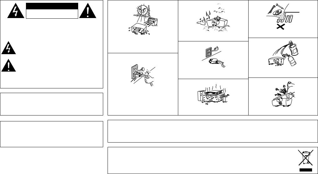
nSAFETY PRECAUTIONS
CAUTION
RISK OF ELECTRIC SHOCK
DO NOT OPEN
CAUTION:
TO REDUCETHE RISK OF ELECTRIC SHOCK, DO NOT REMOVE COVER (OR BACK). NO USER-SERVICEABLE PARTS INSIDE. REFER SERVICING TO QUALIFIED SERVICE PERSONNEL.
The lightning flash with arrowhead symbol, within an equilateral triangle, is intended to alert the user to the presence of uninsulated “dangerous voltage” within the product’s enclosure that may be of sufficient magnitude to constitute a risk of electric shock to persons.
The exclamation point within an equilateral triangle is intended to alert the user to the presence of important operating and maintenance (servicing) instructions in the literature
accompanying the appliance.
WARNING:
TO REDUCE THE RISK OF FIRE OR ELECTRIC SHOCK, DO NOT EXPOSE THIS APPLIANCE TO RAIN OR MOISTURE.
DECLARATION OF CONFORMITY
We declare under our sole responsibility that this product, to which this declaration relates, is in conformity with the following standards: EN60065, EN55013, EN55020, EN61000-3-2 and EN61000-3-3.
Following the provisions of 2006/95/EC and 2004/108/EC Directive.
CAUTION:
To completely disconnect this product from the mains, disconnect the plug from the wall socket outlet.
The mains plug is used to completely interrupt the power supply to the unit and must be within easy access by the user.
nNOTE ON USE
• Do not let foreign objects into the unit.
• Keep the unit free from moisture, water, and dust.
• Avoid high temperatures.
Allow for sufficient heat dispersion when installed in a rack.
• Unplug the power cord when not using the unit for long |
• Do not let insecticides, benzene, and thinner come in |
periods of time. |
contact with the unit. |
• Handle the power cord carefully.
Hold the plug when unplugging the cord.
* (For apparatuses with ventilation holes) |
|
• Do not obstruct the ventilation holes. |
• Never disassemble or modify the unit in any way. |
CAUTION:
•The ventilation should not be impeded by covering the ventilation openings with items, such as newspapers, tablecloths, curtains, etc.
•No naked flame sources, such as lighted candles, should be placed on the unit.
•Observe and follow local regulations regarding battery disposal.
•Do not expose the unit to dripping or splashing fluids.
•Do not place objects filled with liquids, such as vases, on the unit.
A NOTE ABOUT RECYCLING:
This product’s packaging materials are recyclable and can be reused. Please dispose of any materials in accordance with the local recycling regulations.
When discarding the unit, comply with local rules or regulations.
Batteries should never be thrown away or incinerated but disposed of in accordance with the local regulations concerning battery disposal. This product and the supplied accessories, excluding the batteries, constitute the applicable product according to the WEEE directive.
I

Contents
Getting Started
Accessories······················································································2
Cautions on Handling·····································································3
Cautions on Installation·································································3
About the Remote Control Unit·····················································3
Inserting the Batteries····································································3
Operating Range of the Remote Control Unit································3
Part Names and Functions·····························································4
Front Panel······················································································4 Display····························································································4 Rear Panel·······················································································5 Remote Control Unit·······································································6
Connections
Preparations·····················································································7
Cables Used for Connections·························································7 Video Conversion Function·····························································8
Speaker Connections······································································9
Speaker Installation········································································9 Speaker Connections································································ 9, 10
Connecting Equipment with HDMI connectors························· 11
Connecting the Monitor······························································· 12 Connecting the Playback Components······································· 12 DVD Player···················································································· 12 Record Player················································································ 13 CD Player······················································································ 13 iPod®····························································································· 13 TV/CABLE Tuner············································································ 14 Satellite Receiver·········································································· 14 Connecting the Recording Components····································· 15 Digital Video Recorder·································································· 15 Video Cassette Recorder······························································ 15 CD Recorder / MD Recorder / Tape Deck······································ 16 Connections to Other Devices····················································· 16 Components Equipped with a DENON LINK connector··············· 16 Video Camera / Game Console····················································· 17 Component with Multi-channel Output connectors····················· 17 External Power Amplifier······························································ 17 USB Port·······················································································18 Antenna terminals ······································································· 19 Network Audio··············································································20 Multi-Zone····················································································21 External Controller········································································21 Connecting the Power Cord·························································22
Once Connections are Completed···············································22
GUI Menu Operations
Example of the Display of the GUI Mark at a Title·····················22
Example of Display of Default Values··········································22
Examples of GUI Screen Displays················································23
Example: Browse Menu (Top Menu)············································23 Example: Menus with Illustrations (Auto Setup)··························23 Cursor Position Display·································································23 Operations·····················································································23
GUI Menu Map··············································································24
Auto Setup
Preparations···················································································25
Auto Setup·····················································································26
aAuto Setup···············································································26 Error Messages·······································································27
s Option······················································································27
d Parameter Check·····································································27
Manual Setup
Speaker Setup···············································································28
a Speaker Configuration·····························································28
s Subwoofer Mode·····································································28
d Distance··················································································28
fChannel Level··········································································29
gCrossover Frequency·······························································29
hSurround Speaker····································································29 HDMI Setup···················································································30
a i/p Scaler··················································································30 s Resolution················································································30 d Progressive Mode···································································30
fAspect·····················································································30
gColor Space·············································································30
hRGB Range··············································································30
jAuto Lip Sync···········································································30
kAudio·······················································································30
Audio Setup···················································································30
a EXT. IN Setup···········································································30 s 2ch Direct/Stereo·····································································31 d Downmix Option·····································································31
fAuto Surround Mode·······························································31
gManual EQ···············································································31 Network Setup··············································································32
a Network Setup········································································32
s Other·······················································································33
d Network Information·······························································33
Zone Setup····················································································33
a ZONE2·····················································································33
s ZONE3·····················································································33
Option Setup·················································································34
a Amp Assign·············································································34
s Volume Control········································································34
d Source Delete··········································································34
fGUI····················································································34, 35
gQuick Select Name··································································35
hTrigger Out 1············································································35
jTrigger Out 2············································································35
kRemote ID···············································································35
l2Way Remote··········································································35 A0Dimmer····················································································35 A1Setup Lock···············································································36 A2Maintenance Mode·································································36
A3Firmware Update·····································································36
Language·······················································································36
Source Select
Input Source Selection·································································37
Settings Related to Playing Input Sources·································37
a Play··························································································37 s Auto Preset··············································································37 d Preset Skip··············································································37
fPreset Name············································································38
gInput Mode··············································································38
hRename···················································································38
jOther·······················································································38
kPlayback Mode (iPod)·······························································39
lAssign······················································································39 A0Playback Mode········································································40
Surround Modes
Standard Playback········································································40
Surround Playback of 2-channel Sources······································40 Playing Multi-channel Sources (Dolby Digital, DTS, etc.)··············40 DSP Simulation Playback·····························································41
Stereo Playback·············································································41
Direct Playback··············································································41
Playback in the PURE DIRECT Mode···········································41
Parameter
Audio······························································································42
a Surround Parameters·························································42, 43
s Tone·························································································43
d Room EQ·················································································44
fRESTORER··············································································44
gNight Mode··············································································44
hAudio Delay·············································································44 Picture Adjust················································································45
a Contrast···················································································45
s Brightness···············································································45
d Chroma Level···········································································45
f Hue··························································································45

Troubleshooting Information Zone-Multi Control Remote Playback Setup Connections Started Getting
Information
Status·····························································································45
a MAIN ZONE·············································································45
s ZONE2/3··················································································45
Audio Input Signal········································································45
HDMI Information··········································································46
a Signal Information····································································46
s Monitor····················································································46
Auto Surround···············································································46
Quick Select···················································································46
Preset Station················································································46
Playback
Preparations···················································································47
Turning the Power On···································································47 Operations During Playback··························································47 Playing Video and Audio Equipment···········································47
Basic Operation············································································47
Listening to FM/AM Broadcasts··················································48
Basic Operation············································································48
Presetting Radio Stations (Preset Memory)·································48
Listening to Preset Stations·························································49 RDS (Radio Data System)·····························································49 RDS Search···················································································49 PTY Search···················································································50
TP Search······················································································50 RT (Radio Text)··············································································51
iPod® Playback··············································································51
Basic Operation············································································51
Listening to Music········································································52 Viewing Still Pictures or Videos on the iPod·································52
Playing Network Audio or USB Memory Devices······················53
Basic Operation············································································54
Listening to Internet Radio·····················································54, 55 Presetting Internet Radio Stations················································55 Registering Internet Radio Stations as Your Favorites··················55 Playing Files Stored on a Computer··············································55 Playing Files Stored on USB Memory Devices·····························56 Operating the AVR-3808 Using a Browser (Web control)·············57
Other Operations and Functions
Other Operations··········································································57
Playing Super Audio CD································································57 Recording on an External Device (REC OUT mode)·····················58
Convenient Functions···································································59
Channel Level···············································································59
Fader Function··············································································59
Quick Select Function···································································59
Personal Memory Plus Function···················································59
Last Function Memory·································································59
Backup Memory···········································································59
Resetting the Microprocessor······················································59
Remote Control Unit Operations
Main Remote Control Unit···························································60
Operating DENON Audio Components········································60 Presetting·····················································································60 Operating Preset Components·············································60 ~ 62 Setting the Remote ID··································································63 Learning Function·········································································63
System Call Function····································································64
Punch Through Function································································64 Setting the Time the Backlight Stays Lit·······································65
Adjusting the Backlight’s Brightness·············································65 Resetting the Main Remote Control Unit·····································65
Sub Remote Control Unit Operations···································66, 67 Switching Zones···········································································68
Setting the Zone for Which the Sub Remote Control Unit is Used (ZONE SELECT LOCK mode)·······················································68 Setting the Remote ID··································································68 Resetting the Settings··································································68
Amp Assign / Multi-Zone Connections and Operations
Multi-Zone Settings with the Amp Assign Function··········69 ~ 71 Multi-Zone Settings and Operations with Zone Pre-out Output····71
Multi-Zone Operations·································································72
Turning the Power On and Off······················································72 Selecting the Input Source···························································72
Adjusting the Volume····································································72 Turning off the Sound Temporarily················································72
Other Information································································73 ~ 82
Troubleshooting···································································83 ~ 85
Specifications··············································································· 86
List of preset codes············································ End of this manual
Getting Started
Thank you for purchasing this DENON product. To ensure proper operation, please read these owner’s manual carefully before using the product.
After reading them, be sure to keep them for future reference.
Accessories
Check that the following parts are supplied with the product.
q Owner’s manual....................................................................... |
|
1 |
w Service station list.................................................................... |
|
1 |
e Power cord (Cord length: Approx. 1.5 m)................................. |
1 |
|
r Main remote control (RC-1068)................................................ |
1 |
|
t LR6/AA batteries (for RC-1068)................................................ |
2 |
|
y Sub remote control (RC-1070).................................................. |
1 |
|
u R03/AAA batteries (for RC-1070).............................................. |
2 |
|
i FM indoor antenna................................................................... |
|
1 |
o AM loop antenna...................................................................... |
|
1 |
Q0Setup microphone (Cord length: Approx. 7.6 m)...................... |
1 |
|
e |
r |
y |
i |
o |
Q0 |
Cautions on Handling
•Before turning the power switch on
Check once again that all connections are correct and that there are no problems with the connection cables.
•Power is supplied to some of the circuitry even when the unit is set to the standby mode. When traveling or leaving home for long periods of time, be sure to unplug the power cord from the power outlet.
•About condensation
If there is a major difference in temperature between the inside of the unit and the surroundings, condensation (dew) may form on the operating parts inside the unit, causing the unit not to operate properly.
If this happens, let the unit sit for an hour or two with the power turned off and wait until there is little difference in temperature before using the unit.
•Cautions on using mobile phones
Using a mobile phone near this unit may result in noise. If so, move the mobile phone away from this unit when it is in use.
•Moving the unit
Turn off the power and unplug the power cord from the power outlet.
Next, disconnect the connection cables to other system units before moving the unit.
•Note that the illustrations in these instructions may differ from the actual unit for explanation purposes.
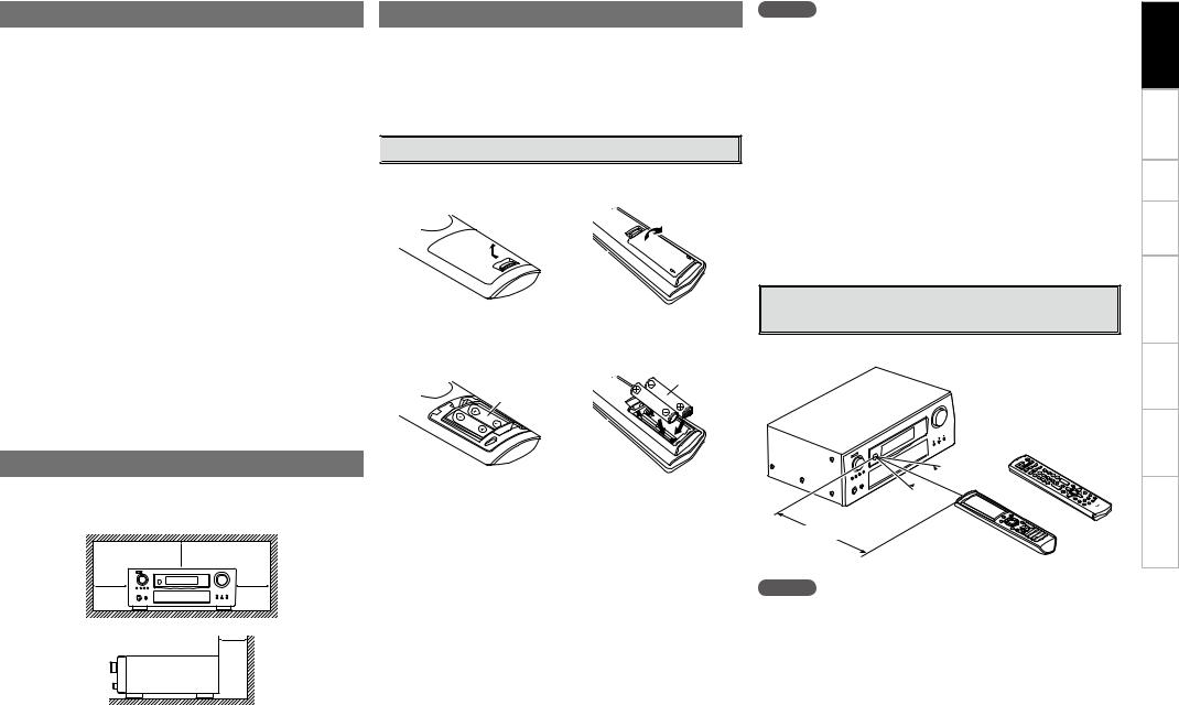
About the Remote Control Unit
In addition to the AVR-3808, the included main remote control unit (RC-1068) can also be used to operate the equipment listed below. q DENON system components
wNon-DENON system components
•By setting the preset memory (vpage 60 ~ 62)
•By using the learn function (vpage 63)

 Inserting the Batteries
q Lift the clasp and remove the rear lid.
(RC-1068) |
(RC-1070) |
w Load the two batteries properly as indicated by the marks in the battery compartment.
(RC-1068) |
(RC-1070) |
R03/AAA
LR6/AA
NOTE
•Replace the batteries with new ones if the set does not operate even when the remote control unit is operated close to the unit.
•The supplied batteries are only for verifying operation.
•When inserting the batteries, be sure to do so in the proper direction, following the “q” and “w” marks in the battery compartment.
•To prevent damage or leakage of battery fluid:
•Do not use a new battery together with an old one.
•Do not use two different types of batteries.
•Do not attempt to charge dry batteries.
•Do not short-circuit, disassemble, heat or dispose of batteries in flames.
•If the battery fluid should leak, carefully wipe the fluid off the inside of the battery compartment and insert new batteries.
•Remove the batteries from the remote control unit if it will not be in use for long periods.
•When replacing the batteries, have the new batteries ready and insert them as quickly as possible.
Operating Range of the Remote Control
Unit
Point the remote control unit at the remote sensor when operating it.
Cautions on Installation
Note:
For proper heat dispersal, do not install this unit in a confined e Put the rear cover back on. space, such as a bookcase or similar enclosure.
|
b Note |
b |
b |
b |
Wall |
(RC-1070)
 30°
30°
30° or
Approx. 7 m
(RC-1068)
NOTE
The set may function improperly or the remote control unit may not operate if the remote control sensor is exposed to direct sunlight, strong artificial light from an inverter type fluorescent lamp or infrared light.
Troubleshooting Information Zone-Multi Control Remote Playback Setup Connections Started Getting

Troubleshooting Information Zone-Multi Control Remote Playback Setup Connections Started Getting
Part Names and Functions
For buttons not explained here, see the page indicated in parentheses ( ).

 Front Panel
o i |
u |
y |
|
t |
|||||
|
|
|
|
|
|
|
|
|
|
|
|
|
|
|
|
|
|
|
|
|
|
|
|
|
|
|
|
|
|
|
|
|
|
|
|
|
|
|
|
Q0Q1Q2 Q3
q w e |
r |
GWith the door openH
E3E2E1E0W9W8 |
W7W6W5W4W3 |
Q4Q5Q6Q7Q8Q9W0W1 W2 |
|
q Power operation button (ON/STANDBY)············································ (47)
w Power indicator··········································· (47) e Power switch (hON jOFF)······················ (47) r QUICK SELECT buttons / indicators·········· (59)
tMASTER VOLUME control knob················ (47)
yMaster volume indicator
uDisplay
i Remote control sensor································· (3) o SOURCE SELECT knob······························· (37) Q0SOURCE button··········································· (37)
Q1TUNING PRESET button····························· (49)
Q2ZONE2/3 / REC SELECT button··········· (58, 72)
Q3VIDEO SELECT button································ (38)
Q4Headphones jack (PHONES)······················· (47)
Q5ZONE2 ON/OFF button······························· (72)
Q6ZONE3 ON/OFF button······························· (72)
Q7INPUT MODE button··································· (38)
Q8MENU button·············································· (23)
Q9Cursor buttons (uio p)··························· (23)
W0CH SEL / ENTER button························ (23, 59)
W1RETURN button··········································· (23)
W2V.AUX INPUT connectors··························· (17)
W3SETUP MIC jack··········································· (25)
W4ROOM EQ button········································ (44)
W5DIMMER button··········································· (35)
W6USB port······················································ (18)
W7STATUS button············································ (45)
W8AUDIO DELAY button·································· (44)
W9RESTORER button······································· (44)
E0DIRECT/STEREO button····························· (41) |
E2DSP SIMULATION button··························· (41) |
E1PURE DIRECT button·································· (41) |
E3STANDARD button······································ (40) |

 Display
|
Q7 |
Q6 |
Q4 |
Q0i |
u |
y |
|
|
Q5Q3 |
Q2Q1o |
|
||||
q |
w |
|
e |
|
|
|
r t |
q Input signal indicators |
|
Q2AL24 indicator |
|
|
|
||
w Input signal channel indicators |
This |
lights when |
AL24 |
Processing Plus is |
|||
activated (vpage 75). |
|
|
|||||
These light when digital signals are input. |
|
|
|||||
|
|
|
|
|
|||
e Information display
The input source name, surround mode, setting values and other information are displayed here.
r Output signal channel indicators
t Surround speaker indicators
These light according to the settings of the surround A and B speakers.
y Master volume indicator
u AUDYSSEY MULTEQ XT indicator
This lights when the room equalizer is selected.
i Recording output source indicator
This lights when the REC OUT mode is selected.
o NIGHT indicator
This lights when the night mode is selected.
Q0Multi-zone indicators
These light when the power for the respective zone is turned on.
Q1RESTORER indicator
This lights when the RESTORER mode is selected.
Q3D.LINK indicator
This lights when playing using DENON LINK connections.
Q4Input mode indicators
Q5HDMI indicator
This lights when playing using HDMI connections.
Q6Decoder indicators
These light when the respective decoders are operating.
Q7Tuner reception mode indicators
These light according to the reception conditions when the input source is set to “TUNER”.
•AUTO
This lights when in the auto tuning mode.
•RDS
This lights when receiving RDS broadcasts.
•STEREO
In the FM mode, this lights when receiving analog stereo broadcasts.
•TUNED
This lights when the broadcast is properly tuned in.


 Rear Panel
Q5 |
Q4 |
Q3 |
Q2 |
Q1Q0 |
o |
|
Q6 |
|
|
Q7 |
Q8 |
Q7 |
Q6 |
Q9 |
|
q |
w |
e |
r |
t |
|
y |
|
u |
i |
q RS-232C connector······································ (21) |
i AC inlet (AC IN)··········································· (22) |
Q5VIDEO / S-VIDEO connectors····················· (12) |
|
||||||
w REMOTE CONTROL jacks··························· (21) |
o Digital audio connectors |
|
Q6Analog audio connectors (AUDIO)············ (12) |
|
|||||
e TRIGGER OUT jacks···································· (21) |
(OPTICAL / COAXIAL)··························· (12, 14) |
Q7PRE OUT connectors······························ (17, 21) |
|
||||||
r FM/AM antenna terminals |
|
|
Q0ETHERNET connector································· (20) |
Q8EXT. IN connectors······································ (17) |
|
||||
(TUNER ANTENNA)····································· (19) |
Q1USB port······················································ (18) |
Q9SIGNAL GND terminal································ (13) |
|
||||||
t DOCK CONTROL jack·································· (13) |
Q2DENON LINK connector······························ (16) |
|
|
|
|
||||
y Speaker terminals (SPEAKERS)··················· (9) |
Q3COMPONENT VIDEO connectors··············· (12) |
|
|
|
|
||||
u AC OUTLET·················································· (22) |
Q4HDMI connectors··········································(11) |
|
|
|
|
||||
Troubleshooting Information Zone-Multi Control Remote Playback Setup Connections Started Getting

Troubleshooting Information Zone-Multi Control Remote Playback Setup Connections Started Getting

 Remote Control Unit
n Main remote control unit (RC-1068) |
n Sub remote control unit (RC-1070) |
Q5
q |
w


 Q6 e
Q6 e

Q7
r |
|
|
t |
Q8 |
|
y |
Q9 |
|
u |
W0 |
|
i |
||
W1 |
||
|
||
o |
W2 |
|
|
||
Q0 |
|
|
Q1 |
W3 |
|
W4 |
||
Q2 |
||
|
Q3 

 W5
W5
W6
Q4

 W7
W7
q Signal transmission indicator···················· (60) w Mode select buttons··································· (60) e Quick select / System call buttons······ (59, 64) r Surround mode buttons······················· (40, 41)
t System buttons····································· (61, 62) y Audio delay button (A. DL)························· (44) u Tuner system buttons································· (48) i Input mode button (INPUT)······················· (38) o MENU button·············································· (23) Q0Cursor buttons (uio p)·························· (23)
Q1Parameter / Search button
(PARA / SRCH)······································· (42, 49) Q2HOME button··············································· (60) Q3Channel buttons (CH)································· (48)
Q4Input source select / Number buttons····(37, 48)
Q5Remote control signal transmitter·············· (3)
Q6Device select indicators (DEV1 / DEV2)···· (60)
Q7ZONE3 select indicators (Z3)······················ (72)
Q8RESTORER button (RSTR)·························· (44)
Q9Night button (NGT)····································· (44)
W0Test tone button (TEST)······························ (29)
W1Surround speaker select button (SPKR)···· (29)
W2POWER buttons··········································· (47)
W3Channel select (CH SEL) /
ENTER button········································ (23, 59) W4Return button (RTN)···································· (23)
W5Master volume control buttons (VOL)······· (47)
W6Muting button (MUTE)··························(47, 72)
W7Main remote control unit setup button
(RC SETUP)·················································· (60)
The time for which the backlight stays on can be changed (vpage 65 “Setting the Time the Backlight Stays Lit”).
NOTE
•The M. SEL, SAT TU, DTU buttons cannot be used.
•The ZONE2 mode QUICK SELECT (1 ~ 3), A.DL, RSTR, NGT, INPUT, SPKR, TEST and surround mode buttons cannot be used.
•The ZONE4 mode cannot be used.
Q1
q


 Q2
Q2
 Q3
Q3
w
e


r |
Q4 |
t |
Q5 |
y |
|
|
Q6 |
u |
|
i |
Q7 |
|
Q8 |
o |
Q9 |
Q0 |
W0 |
qZONE indicators·········································· (68)
wAdvanced setup button······························ (68)
eInput source select buttons························ (37)
rCHANNEL buttons······································ (48)
tSHIFT button··············································· (48)
yMENU button·············································· (23)
uCursor buttons (uio p)·························· (23)
iSEARCH button··········································· (49)
oREPEAT button············································ (52) Q0RANDOM button········································· (52)
Q1Remote control signal transmitter·············· (3)
Q2ZONE SELECT button································· (68)
Q3Zone power on/off buttons
(ZONE ON / ZONE OFF)······························ (72)
Q4Master volume control buttons (VOLUME)············································· (66, 67)
Q5Muting button (MUTE)··························(47, 72)
Q6ENTER button·············································· (23)
Q7RETURN button··········································· (23)
Q8System buttons······························· (48, 66, 67)
Q9ALL MUSIC/FAVORITES
(DIRECT PLAY) button································ (66) W0USB (DIRECT PLAY) button························ (66)
NOTE
The AUX-1, AUX-2, AUX-3, SAT TU, DTU, DVR-2 and OPTION buttons cannot be used.

Connections
Connections for all compatible audio and video signal formats are described in these operating instructions. Please select the types of connections suited for the equipment you are connecting.
With some types of connections, certain settings must be made on the AVR-3808. For details, refer to the instructions for the respective connection items below.
NOTE
•Do not plug in the power cord until all connections have been completed.
•When making connections, also refer to the operating instructions of the other components.
•Be sure to connect the left and right channels properly (left with left, right with right).
•Do not bundle power cords together with connection cables. Doing so can result in humming or noise.
Preparations

 Cables Used for Connections
Select the cables according to the equipment being connected.
|
Audio cables |
|
|
Video cables |
|
|
Coaxial digital connections |
|
Component video connections |
|
|
||
(Orange) |
|
|
(Green) |
|
|
(Y) |
|
|
|
|
|
|
|
|
Coaxial digital (75 Ω/ohms pin-plug) cable |
(Blue) |
|
|
(PB/CB) |
|
Optical digital connections |
|
(Red) |
|
|
(PR/CR) |
|
|
|
Component video cable |
|
|||
|
|
|
|
|
||
|
Optical cable |
|
S-Video connections |
|
|
|
Analog connections (stereo) |
|
|
|
|
|
|
(White) |
L |
L |
|
S-Video cable |
|
|
|
|
|
|
|||
(Red) |
R |
R |
Video connections |
|
|
|
|
|
|
|
|
||
|
Stereo pin-plug cable |
|
(Yellow) |
|
|
|
|
|
|
|
|
|
|
Analog connections (monaural, for subwoofer) |
|
75 Ω/ohms pin-plug video cable |
|
|||
(Black) |
|
|
|
Audio and video cables |
|
|
|
Pin-plug cable |
|
|
|
||
|
|
HDMI connections |
|
|
||
|
|
|
|
|
||
DENON LINK connections |
|
|
|
|
|
|
|
DENON LINK cable |
|
|
19-pin HDMI cable |
|
|
|
|
|
|
|
|
|
Speaker connections |
|
|
Signal direction |
|
||
|
|
|
Audio signal: |
|
Video signal: |
|
|
Speaker cables |
|
Output |
Input |
Output |
Input |
|
|
|
|
|
|
|
Network connections |
|
|
|
|
|
|
|
Ethernet cable |
|
Input |
Output |
Input |
Output |
|
|
|
|
|
|
|
Troubleshooting Information Zone-Multi Control Remote Playback Setup Connections Started Getting

Troubleshooting Information Zone-Multi Control Remote Playback Setup Connections Started Getting

 Video Conversion Function
•This function automatically converts various formats of video signals input to the AVR-3808 into the format used to output the video signals from the AVR-3808 to a monitor.
•The AVR-3808’s video input/output circuitry is compatible with the following four types of video signals: Digital video signals: HDMI
Analog video signals: Component video, S-Video and Video
GFlow of video signals inside the AVR-3808H |
|
||
Main zone |
|
|
|
High picture |
HDMI connector |
HDMI connector |
|
quality playback |
|
||
|
Component video |
Component video |
Monitor |
|
connectors |
connectors |
|
|
S-Video connector |
S-Video connector |
|
|
Video connector |
Video connector |
|
|
Video inputs |
Video outputs |
|
|
: When 480i/576i signals are input in the main zone |
|
|
|
GFlow of video signals for ZONE2H |
|
|
ZONE2 |
|
|
|
High picture |
|
|
|
quality playback |
S-Video connector |
|
ZONE2 |
|
|
monitor |
|
|
|
|
|
|
Video connector |
Video connector |
|
|
Video inputs |
Video outputs |
|
•When not using this function, connect a monitor output with the same type of connector as the video input connector.
•The resolution of the HDMI input-compatible monitor connected to the AVR-3808 can be checked at GUI menu “Information” – “HDMI Information” – “Monitor” (vpage 46).
NOTE
•HDMI signals cannot be converted into analog signals.
•1080p component input video signals cannot be output to anything other than component video connectors.
•480p/576p, 1080i and 720p component video input signals cannot be converted into S-Video or Video format.
•When a non-standard video signal from a game machine or some other source is input, the video conversion function might not operate.
Speaker Connections

 Speaker Installation
The illustration below shows a basic example of installation of the amplifier combined with 8 speakers and a monitor.
Subwoofer |
Center speaker |
Surround back speakers
Front speakers |
|
|
Place the front speakers to the |
|
|
Surround speakers |
||
sides of the monitor or screen and |
||
|
||
as flush with the screen surface as |
|
|
possible. |
|
The table below shows a typical speaker configuration for the AVR-3808.
|
FRONT |
|
SURROUND SURROUND |
SURROUND |
|
||||||
|
|
|
A |
|
B |
|
BACK |
|
|
||
|
|
|
CENTER |
|
|
|
|
SUBWOOFER |
|||
|
|
|
|
|
|
|
|
|
1 |
||
|
L |
R |
|
L |
R |
L |
R |
L |
R |
|
|
|
|
only |
|
||||||||
|
|
|
|
|
|
|
|
|
|
|
|
7.1-channels |
S |
S |
S |
S |
S |
S |
S |
S |
S |
– |
S |
(Surround A+B) |
|||||||||||
7.1-channels |
S |
S |
S |
S |
S |
– |
– |
S |
S |
– |
S |
6.1-channels |
S |
S |
S |
S |
S |
– |
– |
– |
– |
S |
S |
5.1-channels |
S |
S |
S |
S |
S |
– |
– |
– |
– |
– |
S |
3.1-channels |
S |
S |
S |
– |
– |
– |
– |
– |
– |
– |
S |
2.1-channels |
S |
S |
– |
– |
– |
– |
– |
– |
– |
– |
S |
2-channels |
S |
S |
– |
– |
– |
– |
– |
– |
– |
– |
– |

 Speaker Connections
Example: 7.1-channels (Surround A+B)
Front speakers |
|
Center speaker |
|
Subwoofer |
|
|
|
|
|
|
|
|
|
|
|
|
|
|
Subwoofer |
||
|
|
|
|
|
|
|
|
|
with built-in |
||
(L) |
|
|
(R) |
|
|
|
|
|
amplifier |
|
|
w |
q |
w |
q |
|
w |
q |
|
|
|
|
|
|
|
|
|
|
|
|
*/ |
|
|
||
|
|
|
|
|
|
|
|
|
|
|
|
b L : Left |
|
|
|
|
|
|
|
|
|
|
|
R : Right |
|
|
|
|
|
|
|
|
|
|
|
|
|
|
(L) |
|
(R) |
(L) |
|
(R) |
(L) |
(R) |
|
|
|
|
w |
q w |
q |
w |
qw |
q |
w |
qw |
q |
Surround speakers |
|
Surround speakers |
|
Surround Back |
A |
|
B |
|
speakers |
When using just one surround back speaker, connect it to the left channel (SBL).
Troubleshooting Information Zone-Multi Control Remote Playback Setup Connections Started Getting
Troubleshooting Information Zone-Multi Control Remote Playback Setup Connections Started Getting
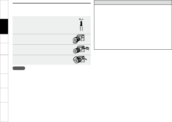
Connecting the Speaker Cables
Carefully check the left (L) and right (R) channels and + (red) and – (black) polarities on the speakers being connected to the AVR-3808, and be sure to interconnect the channels and polarities correctly.
1Peel off about 10 mm of sheathing from the tip of the speaker cable, then either twist the core wire tightly or terminate it.
Turn |
the |
speaker |
terminal |
2counterclockwise to loosen it. |
|
||
3Insert the speaker cable’s core wire to the hilt into the speaker terminal.
4Turn the speaker terminal clockwise to tighten it.
NOTE
•Use speakers with an impedance of 6 to 16 Ω/ohms. When using surround A and B speakers simultaneously, use speakers with an impedance of 8 to 16 Ω/ohms.
•Connect the speaker cables in such a way that they do not stick out of the speaker terminals. The protection circuit may be activated if the core wires touch the rear panel or if the + and – sides touch each other (v“Protection circuit”).
•Never touch the speaker terminals while the power supply is connected. Doing so could result in electric shock.
Protection circuit
If speakers with an impedance lower than specified (for example 4 Ω/ohms speakers) are used for an extended period of time with the volume turned up high, the temperature may rise, activating the protection circuit.
When the protection circuit is activated, the speaker output is shut off and the power indicator flashes red. If this happens, unplug the power cord, then check the speaker cable and input cable connections. If the set is extremely hot, wait for it to cool off and improve ventilation around it. Once this is done, plug the power cord back in and turn the set’s power back on.
If the protection circuit is activated again even though there are no problems in the ventilation around the set nor in the connections, the set may be damaged. Turn the power off, then contact a DENON service center.
10

Connecting Equipment with HDMI connectors
With HDMI connections, the video and audio signals can be transferred with a single cable.
|
|
|
DVD player |
Monitor |
|
)%.* |
|
)%.* |
065 |
|
*/ |
b The AVR-3808 is equipped for HDMI version 1.3a. This version is compatible with other versions, allowing connection to all components equipped with an HDMI connector.
b The AVR-3808 is compatible with 30and 36-bit Deep Color.
|
|
|
|
|
|
|
|
|
|
|
|
|
|
|
|
|
|
|
|
|
Compatible |
Details |
Discs |
|
|
|
|
|
|
|
|
|
|
|
|
|
|
|
|
|
|
|
|
||||
|
|
|
|
|
|
|
|
|
|
|
|
|
|
|
|
|
|
|
|
|
audio format |
(examples) |
|
|
|
|
|
|
|
|
|
|
|
|
|
|
|
|
|
|
|
|
|
|
|
||
|
|
|
|
|
|
|
|
|
|
|
|
|
|
|
|
|
|
|
|
|
|
|
|
|
|
|
|
|
|
|
|
|
|
|
|
|
|
|
|
|
|
|
|
|
2-channel linear |
2ch 32-192 kHz |
CD, DVD-Video, |
|
|
|
|
|
|
|
|
|
|
|
|
|
|
|
|
|
|
|
|
|
PCM |
16/20/24 bits |
DVD-Audio |
|
|
|
|
|
|
|
|
|
|
|
|
|
|
|
|
|
|
|
|
||||
|
|
|
|
|
|
|
|
|
|
|
|
|
|
|
|
|
|
|
|
|
|
|
|
|
|
|
|
|
|
|
|
|
|
|
|
|
|
|
|
|
|
|
|
|
Multi-channel |
8ch 32-192 kHz |
DVD-Audio |
|
|
|
|
|
|
|
|
|
|
|
|
|
|
|
|
|
|
|
|
||||
|
|
|
|
|
|
|
|
|
|
|
|
|
|
|
|
|
|
|
|
||||
|
|
|
|
|
|
|
|
|
|
|
|
|
|
|
|
|
|
|
|
|
linear PCM |
16/20/24 bits |
|
|
|
|
|
|
|
|
|
|
|
|
|
|
|
|
|
|
|
|
|
|
|
||
|
|
|
|
|
|
|
|
|
|
|
|
|
|
|
|
|
|
|
|
|
|
|
|
|
|
|
|
|
|
|
|
|
|
|
|
|
|
|
|
|
|
|
|
|
Dolby Digital, DTS |
Bitstream |
DVD-Video |
|
|
|
|
|
|
|
|
|
|
|
|
|
|
|
|
|
|
|
|
|
|
2/5.1ch |
|
|
|
|
|
|
|
|
|
|
|
|
|
|
|
|
|
|
|
|
|
|
DSD |
2.8224 MHz |
SACD |
|
|
|
|
|
|
|
|
|
|
|
|
|
|
|
|
|
|
|
|
||||
|
|
|
|
|
|
|
|
|
|
|
|
|
|
|
|
|
|
|
|
||||
|
|
|
|
|
|
|
|
|
|
|
|
|
|
|
|
|
|
|
|
|
|
1 bit |
|
|
|
|
|
|
|
|
|
|
|
|
|
|
|
|
|
|
|
|
|
|
|
|
|
|
|
|
|
|
|
|
|
|
|
|
|
|
|
|
|
|
|
|
|
|
|
|
|
|
|
|
|
|
|
|
|
|
|
|
|
|
|
|
|
|
|
|
|
|
|
|
|
|
|
|
|
|
|
|
|
|
|
|
|
|
|
|
|
|
|
|
|
|
Dolby Digital Plus, |
|
HD DVD, |
|
|
|
|
|
|
|
|
|
|
|
|
|
|
|
|
|
|
|
|
|
|||
|
|
|
|
|
|
|
|
|
|
|
|
|
|
|
|
|
|
|
|
|
Dolby TrueHD, |
Bitstream |
|
|
|
|
|
|
|
|
|
|
|
|
|
|
|
|
|
|
|
|
|
|
Blu-ray Disc |
||
|
|
|
|
|
|
|
|
|
|
|
|
|
|
|
|
|
|
|
|
|
DTS-HD |
|
|
|
|
|
|
|
|
|
|
|
|
|
|
|
|
|
|
|
|
|
|
|
|
|
|
|
|
|
|
|
|
|
|
|
|
|
|
|
|
|
|
|
|
|
|
|
|
|
|
Copyright protection system (HDCP)
In order to play the digital video and audio signals of a DVDVideo or DVD-Audio disc using HDMI/DVI connections, both the connected DVD player and monitor must be equipped for a copyright protection system called “HDCP” (Highbandwidth Digital Content Protection).
HDCP is a copy protection technology consisting of data encoding and mutual identification of the devices.
The AVR-3808 is HDCP-compatible. For details on the DVD player or monitor you are using, refer to its operating instructions.
• By default, the HDMI audio signals are output from the speakers connected to the AVR-3808.
• To output the sound from the TV, make the settings at GUI menu “Manual Setup” – “HDMI Setup”
– “Audio” – “TV” (vpage 30).
NOTE
•Use a CPPM-compatible DVD player to play DVD-Audio discs that are copyright-protected by CPPM.
•The AVR-3808 cannot be controlled from another device via the HDMI cable.
•The audio signals output from the HDMI connector (sampling frequency, bit rate, etc.) may be restricted by the connected device.
•Video signals are not output properly when using devices that are not HDCP-compatible.
•Video signals are not output if the input video signals do not match the monitor’s resolution. In this case, switch the DVD player’s resolution to a resolution with which the monitor is compatible.
•If the GUI menu “Manual Setup” – “HDMI Setup” – “Audio” setting (vpage 30) is set to “Amp”, the sound may be interrupted when the monitor’s power is turned off.
•Use a cable on which the HDMI logo is indicated (a certified HDMI product) for connection to the HDMI connector. Normal playback may not be possible when using a cable other than one on which the HDMI logo is indicated (a non-HDMI-certified product).
•If the monitor or DVD player does not support deep color, deep color signal transfer is not possible.
•If the monitor or DVD player does not support xvYCC, xvYCC signal transfer is not possible.
•If the monitor does not support “Auto Lipsync Correction” function, this function will not work.
•When the AVR-3808 and DVD player are connected using an HDMI cable, also connect the AVR-3808 and monitor using an HDMI cable.
•If the connected monitor or DVD player only has a DVI-D connector, use an HDMI/DVI converter cable. When using a DVI cable, no audio signals are transmitted.
•Use a Deep Color compatible cable for connection to Deep Color compatible devices.
When connecting with an HDMI/DVI converter cable (adapter)
•HDMI video signals are theoretically compatible with the DVI format.
When connecting to a monitor, etc., equipped with a DVI-D connector, connection is possible using an HDMI/DVI converter cable, but depending on the combination of components in some cases the video signals will not be output.
•When connecting using an HDMI/DVI converter adapter, the video signals may not be output properly due to poor connections with the connected cable, etc.
Troubleshooting Information Zone-Multi Control Remote Playback Setup Connections Started Getting
11

Troubleshooting Information Zone-Multi Control Remote Playback Setup Connections Started Getting
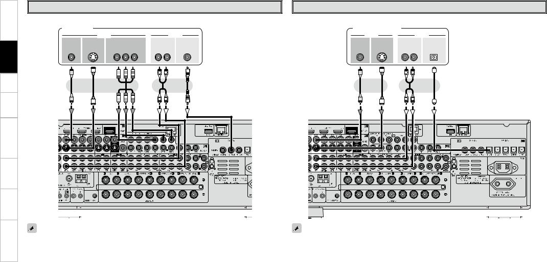
Connecting the Monitor
•Connect the cables to be used (vpage 8 “Video Conversion Function”).
•With HDMI connections, the video and audio signals can be transferred with a single cable.
•To output the audio signals to the monitor with HDMI connections, set GUI menu “Manual Setup”
– “HDMI Setup” – “Audio” to “TV” (vpage 30).
Monitor
|
|
|
|
|
|
|
|
|
|
|
7*%&0 |
|
|
|
|
|
|
|||
|
|
|
|
|
|
|
|
|
|
|
|
|
|
|
|
|
|
|||
)%.* |
7*%&0 |
|
4 7*%&0 |
|
$0.10/&/5 7*%&0 |
|||||||||||||||
*/ |
|
*/ |
|
|
*/ |
|
|
|
*/ |
|
|
|
||||||||
|
|
|
|
|
|
|
|
|
|
|
|
|
|
: 1# 13 |
||||||
|
|
|
|
|
|
|
|
|
|
|
|
|
|
|
|
|
|
|
|
|
|
|
|
|
|
|
|
|
|
|
|
|
|
|
|
|
|
|
|
|
|
|
|
|
|
|
|
|
|
|
|
|
|
|
|
|
|
|
|
|
|
|
|
|
|
|
|
|
|
|
|
|
|
|
|
|
|
|
|
|
|
|
|
|
|
|
|
|
|
|
|
|
|
|
|
|
|
|
|
|
|
|
|
|
|
|
|
|
|
|
|
|
|
|
|
|
|
|
|
|
|
|
|
|
|
|
|
|
|
|
|
|
|
|
|
|
|
|
|
|
|
|
|
|
|
|
Connecting the Playback Components
Carefully check the left (L) and right (R) channels and the inputs and outputs, and be sure to interconnect correctly.

 DVD Player
•Connect the cables to be used.
•With HDMI connections, the video and audio signals can be transferred with a single cable.
DVD player
|
|
7*%&0 |
|
|
"6%*0 |
|
)%.* |
7*%&0 |
4 7*%&0 |
$0.10/&/5 7*%&0 |
"6%*0 |
$0"9*"- |
|
065 |
065 |
065 |
065 |
065 |
065 |
|
|
|
|
: 1# 13 |
- |
3 |
|
|
|
|
|
L |
R |
|
L |
R |
NOTE
•The component video connectors may be indicated differently on your monitor. For details, see the monitor’s operating instructions.
•The audio signals output from the HDMI connectors are only the HDMI input signals.
Video-converted HDMI signals are not included in the audio signals. To play the sound by monitor, make analog or digital audio output connections to monitor’s audio input connectors.
•Connect an HDP (High-Definition Player) in the same way.
•When using an optical cable for the digital audio connection, make the settings at GUI menu “Source Select” – “DVD” – “Assign” – “Digital” (vpage 39).
12

Record Player |
CD Player |
|
Turntable (MM cartridge) |
Connect the cables to be used. |
|
CD player |
|
|
|
|
|
|
"6%*0 |
|
|
"6%*0 |
$0"9*"- |
|
065 |
065 |
|
- 3 |
|
"6%*0 |
(/% |
|
065 |
||
|
||
|
L R |
L 
 R
R
L |
R |
•When connecting a record player with an MC cartridge, use a commercially available MC head amplifier or a step-up transformer.
•Induction humming (a booming sound) may be produced from the speakers if the volume is raised with no record player connected.
•With some record players, noise may be generated when the ground wire is connected. If so, disconnect the ground wire.
NOTE
The AVR-3808’s SIGNAL GND terminal is meant to reduce noise when a record player is connected. This is not a safety ground terminal.
When using an optical cable for the digital audio connection, make the settings at GUI menu “Source Select” – “CD” – “Assign” – “Digital” (vpage 39).

 iPod®
iPod®
Use a DENON Control Dock for iPod (ASD-1R, sold separately) to connect the iPod to the AVR-3808. For instructions on the Control Dock for iPod settings, refer to the Control Dock for iPod’s operating instructions.
Example :
iPod
"4% 3
R |
L |
R |
L |
•With the default settings, the iPod can be used connected to the VCR (iPod) connector.
•To assign the iPod to a connector other than VCR (iPod), make the settings at GUI menu “Source Select” – “(input source to which iPod dock assigned)” – “Assign” – “iPod dock” (vpage 39).
Troubleshooting Information Zone-Multi Control Remote Playback Setup Connections Started Getting
13
Troubleshooting Information Zone-Multi Control Remote Playback Setup Connections Started Getting
TV/CABLE Tuner |
|
|
|
|
|
|
Satellite Receiver |
|
|
|
|
|
Connect the cables to be used. |
|
|
|
|
|
|
Connect the cables to be used. |
|
|
|
|
|
TV tuner |
|
|
|
|
|
|
DBS / BS tuner |
|
|
|
||
|
7*%&0 |
|
|
|
|
"6%*0 |
7*%&0 |
|
|
"6%*0 |
||
7*%&0 |
4 7*%&0 |
$0.10/&/5 7*%&0 |
"6%*0 |
$0"9*"- |
7*%&0 |
4 7*%&0 |
"6%*0 |
015*$"- |
||||
065 |
065 |
|
065 |
|
065 |
065 |
065 |
065 |
065 |
065 |
||
|
|
: |
1# |
13 |
- |
3 |
|
|
|
- |
3 |
|
|
|
|
|
|
L |
R |
|
|
|
L |
R |
|
|
|
|
|
|
L |
R |
|
|
|
L |
R |
|
|
|
|
|
|
|
|
|
|
|
|
|
|
|
|
|
|
|
|
|
|
|
|
|
|
|
|
|
|
|
|
|
|
|
|
|
|
|
|
|
|
|
|
|
|
|
|
|
|
|
|
|
|
|
|
|
|
|
|
|
|
|
|
|
|
|
|
|
|
|
|
|
|
|
|
|
|
|
|
|
|
|
|
|
|
|
|
|
|
|
|
|
|
|
|
|
|
|
|
|
|
|
|
|
|
|
|
|
|
|
|
|
|
|
|
|
|
|
|
|
|
|
|
|
|
|
|
|
|
|
|
|
|
|
|
|
|
|
|
|
|
|
|
|
|
|
|
|
|
|
|
|
|
|
|
|
|
|
|
|
|
|
|
|
|
|
|
|
|
|
|
|
|
|
|
|
|
|
|
|
|
|
|
|
|
|
|
|
|
|
|
|
|
|
|
|
|
|
|
|
|
|
|
|
|
|
|
|
|
|
|
|
|
|
|
|
|
|
|
|
|
|
|
|
|
|
|
|
|
|
|
|
|
|
|
|
|
|
|
|
|
|
|
|
|
|
|
|
|
|
|
|
|
|
|
|
|
|
|
|
|
|
|
|
|
|
|
|
|
|
|
|
|
|
|
|
|
|
|
|
|
|
|
|
|
|
|
|
|
|
|
|
|
|
|
|
|
|
|
|
|
|
|
|
|
|
|
|
|
|
|
|
|
|
|
|
|
|
|
|
|
|
|
|
|
|
|
|
|
|
|
|
|
|
|
|
|
|
|
|
|
|
|
|
|
|
|
|
|
|
|
|
|
|
|
|
|
|
|
|
|
|
|
|
|
|
|
|
|
|
|
|
|
|
|
|
|
|
|
|
|
|
|
|
|
|
|
|
|
|
|
|
|
|
|
|
|
|
|
|
|
|
|
|
|
|
|
|
|
|
|
|
|
|
|
|
|
|
|
|
|
|
|
|
|
|
|
|
|
|
|
|
|
|
|
|
|
|
|
|
|
|
|
|
|
|
|
|
|
|
|
|
|
|
|
|
|
|
|
|
|
|
|
|
|
|
|
|
|
|
|
|
|
|
|
|
|
|
|
|
|
|
|
|
|
|
|
|
|
|
|
|
|
|
|
|
|
|
|
|
|
|
|
|
|
|
|
|
|
|
|
|
|
|
|
|
|
|
|
|
|
|
|
|
|
|
|
|
|
|
|
|
|
|
|
|
|
|
|
|
|
|
|
|
|
|
|
|
|
|
|
|
|
|
|
|
|
|
|
|
|
|
|
|
|
|
|
|
|
|
|
|
|
|
|
|
|
|
|
|
|
|
|
|
|
|
|
|
|
|
|
|
|
|
|
|
|
|
|
|
|
|
|
|
|
|
|
|
|
|
|
|
|
|
|
|
|
|
|
|
|
|
|
|
|
|
|
|
|
|
|
|
|
|
|
|
|
|
|
|
|
|
|
|
|
|
|
|
|
|
|
|
|
|
|
|
|
|
|
|
|
|
|
|
|
|
|
|
|
|
|
|
|
|
|
|
|
|
|
|
|
|
|
|
|
|
|
|
|
|
|
|
|
|
|
|
|
|
|
|
|
|
|
|
|
|
|
|
|
|
|
|
|
|
|
|
|
|
|
|
|
|
|
|
|
|
|
|
|
|
|
|
|
|
|
|
|
|
|
|
|
|
|
|
|
|
|
|
|
|
|
|
|
|
|
|
|
|
|
|
|
|
|
|
|
|
|
|
|
|
|
|
|
|
|
|
|
|
|
|
|
|
|
|
|
|
|
|
|
|
|
|
|
|
|
|
|
|
|
|
|
|
|
|
|
|
|
|
|
|
|
|
|
|
|
|
|
|
|
|
|
|
|
|
|
|
|
|
|
|
|
|
|
|
|
|
|
|
|
|
|
|
|
|
|
|
|
|
|
|
|
|
|
|
|
|
|
|
|
|
|
|
|
|
|
|
|
|
|
|
|
|
|
|
|
|
|
|
|
|
|
|
|
|
|
|
|
|
|
|
|
|
|
|
|
|
|
|
|
|
|
|
|
|
|
|
|
|
|
|
|
|
|
|
|
|
|
|
|
|
|
|
|
|
|
|
|
|
|
|
|
|
|
|
|
|
|
|
|
|
|
|
|
|
|
|
|
|
|
|
|
|
|
|
|
|
|
|
|
|
|
|
|
|
|
|
|
|
|
|
|
|
|
|
|
|
|
|
|
|
|
|
|
|
|
|
|
|
|
|
|
|
|
|
|
|
|
|
|
|
|
|
|
|
|
|
|
|
|
|
|
|
|
|
|
|
|
|
|
|
|
|
|
|
|
|
|
|
|
|
|
|
|
|
|
|
|
|
|
|
|
|
|
|
|
|
|
|
|
|
|
|
|
|
|
|
|
|
|
|
|
|
|
|
|
|
|
|
|
|
|
|
|
|
|
|
|
|
|
|
|
|
|
|
|
|
|
|
|
|
|
|
|
|
|
|
|
|
|
|
|
|
|
|
|
|
|
|
|
|
|
|
|
|
|
|
|
|
|
|
|
|
|
|
|
|
|
|
|
|
|
|
|
|
|
|
|
|
|
|
|
|
|
|
|
|
|
|
|
|
|
|
|
|
|
|
|
|
|
|
|
|
|
|
|
|
|
|
|
|
|
|
|
|
|
|
|
|
|
|
|
|
|
|
|
|
|
|
|
|
|
|
|
|
|
|
|
|
|
|
|
|
|
|
|
|
|
|
|
|
|
|
|
|
|
|
|
|
|
|
|
|
|
|
|
|
|
|
|
|
|
|
|
|
|
|
|
|
|
|
|
|
|
|
|
|
|
|
|
|
|
|
|
|
|
|
|
|
|
|
|
|
|
|
|
|
|
|
|
|
|
|
|
|
|
|
|
|
|
|
|
|
|
|
|
|
|
|
|
|
|
|
|
|
|
|
|
|
|
|
|
|
|
|
|
|
|
|
|
|
|
|
|
|
|
|
|
|
|
|
|
|
|
|
|
|
|
|
|
|
|
|
|
|
|
|
|
|
|
|
|
|
|
|
|
|
|
|
|
|
|
|
|
|
|
|
|
|
|
|
|
|
|
|
|
|
|
|
|
|
|
|
|
|
|
|
|
|
|
|
|
|
|
|
|
|
|
|
|
|
|
|
|
|
|
|
|
|
|
|
|
|
|
|
|
|
|
|
|
|
|
|
|
|
|
|
|
|
|
|
|
|
|
|
|
|
|
|
|
|
|
|
|
|
|
|
|
|
|
|
|
|
|
|
|
|
|
|
|
|
|
|
|
|
|
|
|
|
|
|
|
|
|
|
|
|
|
|
|
|
When using an optical cable for the digital audio connection, make the settings at GUI menu “Source |
• When using a coaxial digital cable for the digital audio connection, make the settings at GUI menu “Source |
||||||||||||||||||||||||||||||||||||||||||||||||||||||||||||||||||||||||||||||||||||||||||||||||
Select” – “TV/CBL” – “Assign” – “Digital” (vpage 39). |
Select” – “SAT” – “Assign” – “Digital” (vpage 39). |
||||||||||||||||||||||||||||||||||||||||||||||||||||||||||||||||||||||||||||||||||||||||||||||||
|
|
|
|
|
|
|
|
|
|
|
|
|
|
|
|
|
|
|
|
|
|
|
|
|
|
|
|
|
|
|
|
|
|
|
|
|
|
|
|
• When using a component video cable for the video connection, make the settings at GUI menu “Source |
|||||||||||||||||||||||||||||||||||||||||||||||||||||||||
|
|
|
|
|
|
|
|
|
|
|
|
|
|
|
|
|
|
|
|
|
|
|
|
|
|
|
|
|
|
|
|
|
|
|
|
|
|
|
|
Select” – “SAT” – “Assign” – “Component” (vpage 39). |
|||||||||||||||||||||||||||||||||||||||||||||||||||||||||
14
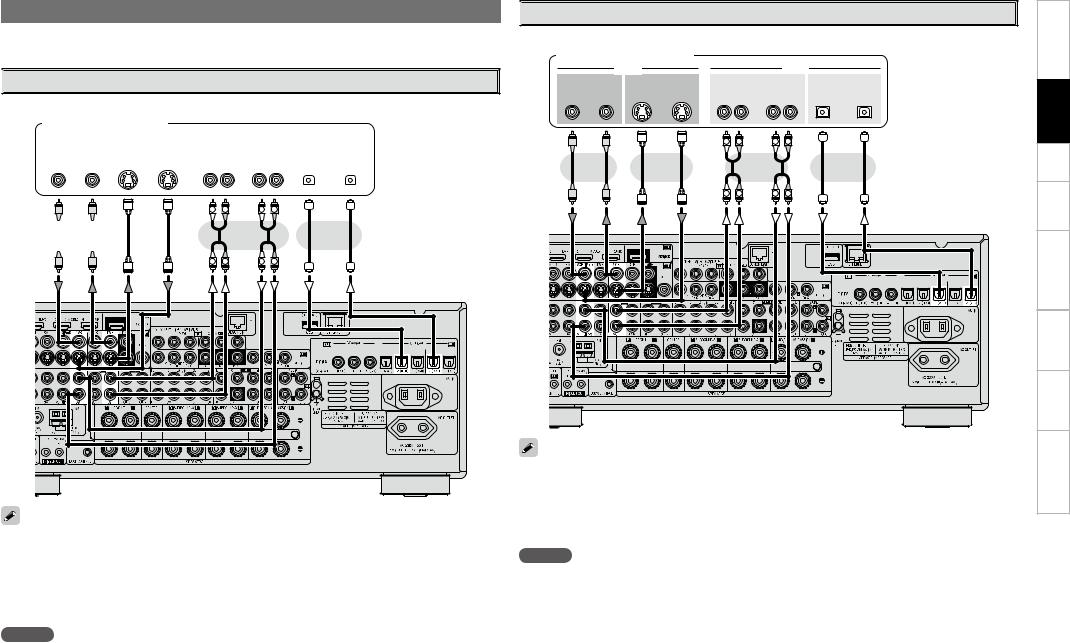
Connecting the Recording Components
Carefully check the left (L) and right (R) channels and the inputs and outputs, and be sure to interconnect correctly.

 Digital Video Recorder
Connect the cables to be used.
Digital video recorder
|
|
7*%&0 |
|
|
|
|
|
|
"6%*0 |
|
|
|
|
|
|||
|
|
|
|
|
|
|
|
|
|
|
|
|
|||||
7*%&0 |
|
|
|
|
|
4 7*%&0 |
|
|
|
"6%*0 |
|
|
|
|
015*$"- |
|
|
065 |
*/ |
|
|
*/ |
065 |
|
|
*/ |
065 |
|
065 |
*/ |
|
||||
|
|
|
|
|
|
|
|
- |
3 |
- 3 |
|
|
|
|
|
|
|
|
|
|
|
|
|
|
|
|
|
|
|
|
|
|
|
|
|
|
|
|
|
|
|
|
|
|
|
|
|
|
|
|
|
|
|
L 
 R
R
 or
or 
L |
R |
L 
 R
R
or
L 
 R
R
•Make analog connections if you wish to record analog audio signals.
•When recording via the AVR-3808, the playback device’s cable must be of the same type as the cable used to connect the AVR-3808’s DVR OUT connector.
Example: TV IN → S-Video cable : DVR OUT → S-Video cable TV IN →Video cable : DVR OUT →Video cable
•When using a component video cable for the video connection, make the settings at GUI menu “Source Select” – “DVR” – “Assign” – “Component” (vpage 39).
NOTE
Do not connect the output of the component connected to the AVR-3808’s OPTICAL2 output connector to any input connector other than OPTICAL2.

 Video Cassette Recorder
Connect the cables to be used.
Video cassette recorder
|
|
7*%&0 |
|
|
|
"6%*0 |
|
|
7*%&0 |
|
|
4 7*%&0 |
|
"6%*0 |
|
|
015*$"- |
065 |
*/ |
*/ |
065 |
*/ |
065 |
065 |
*/ |
|
|
|
|
- |
3 |
- |
3 |
|
|
|
|
|
L |
R |
L |
R |
|
|
|
|
or |
|
|
|
or |
|
|
|
|
|
L |
R |
L |
R |
|
|
•When recording via the AVR-3808, the playback device’s cable must be of the same type as the cable used to connect the AVR-3808’s VCR OUT connector.
Example: TV IN → S-Video cable : VCR OUT → S-Video cable TV IN →Video cable : VCR OUT →Video cable
•When using a component video cable for the video connection, make the settings at GUI menu “Source Select” – “VCR” – “Assign” – “Component” (vpage 39).
NOTE
Do not connect the output of the component connected to the AVR-3808’s OPTICAL3 output connector to any input connector other than OPTICAL3.
Troubleshooting Information Zone-Multi Control Remote Playback Setup Connections Started Getting
15

Troubleshooting Information Zone-Multi Control Remote Playback Setup Connections Started Getting

 CD Recorder / MD Recorder / Tape Deck
Make analog connections if you wish to record analog audio signals, or digital connections if you wish to record digital audio signals, depending on the types of connectors on the components being used.
CD recorder /
MD recorder / Tape deck
|
|
"6%*0 |
|
|
|
"6%*0 |
|
|
015*$"- |
065 |
*/ |
065 |
*/ |
|
- |
3 |
- |
3 |
|
L |
R |
L |
R |
|
or
L |
R |
L |
R |
NOTE
Do not connect the output of the component connected to the AVR-3808’s OPTICAL3 output connector to any input connector other than OPTICAL3.
Connections to Other Devices
Carefully check the left (L) and right (R) channels and the inputs and outputs, and be sure to interconnect correctly.
Components Equipped with a DENON LINK connector
Multi-channel playback is possible with DVD-Audio discs, Super Audio CD, etc.
DVD player
7*%&0
%&/0/ -*/,
To use with DENON LINK connections, make the settings at GUI menu “Source Select” – “Assign” – “Digital” – “DENON LINK” (vpage 39).
16


 Video Camera / Game Console
Video camera / Game console
|
7*%&0 |
|
|
|
|
"6%*0 |
|
|
|
|
|
||||
|
|
|
|
|
|
|
|
|
|
||||||
|
|
|
|
|
|
|
|
|
|
|
|
|
|
|
|
4 7*%&0 |
|
|
7*%&0 |
|
"6%*0 |
|
|
015*$"- |
|||||||
065 |
|
|
065 |
|
065 |
|
|
065 |
|||||||
|
|
|
|
|
|
|
- 3 |
|
|
|
|
|
|
|
|
|
|
|
|
|
|
|
|
|
|
|
|
|
|
|
|
|
|
|
|
|
|
|
|
|
|
|
|
|
|
|
|
|
|
|
|
|
|
|
|
|
|
|
|
|
|
|
|
|
|
|
|
|
|
|
|
|
|
|
|
|
|
|
|
L |
R |
L |
R |
Component with Multi-channel Output connectors
DVD player /
Super Audio CD player / External decoder
|
|
|
"6%*0 |
|
|
|
|
46# |
'30/5 |
$&/5&3 |
463306/% |
463306/% |
|||
800'&3 |
|
|
|
|
|
#"$, |
|
|
- |
3 |
|
- |
3 |
- |
3 |
|
L |
R |
|
L |
R |
L |
R |
|
L |
R |
|
L |
R |
L |
R |

 External Power Amplifier
Power amplifier
|
|
|
"6%*0 |
|
|
|
|
46# |
'30/5 |
$&/5&3 |
463306/% |
463306/% |
|||
800'&3 |
|
|
|
|
|
#"$, |
|
|
- |
3 |
|
- |
3 |
- |
3 |
|
L |
R |
|
L |
R |
L |
R |
|
L |
R |
|
L |
R |
L |
R |
•To play the analog input signals input to the EXT. IN connectors, press the INPUT MODE button on the main unit or INPUT button on the main remote control unit and select “EXT. IN” or make the settings at GUI menu “Source Select” – “(input source)” – “Input Mode” – “Input Mode” – “EXT. IN” (vpage 38).
•The video signal can be connected in the same way as a DVD player (vpage 12).
•To play copyright-protected discs, connect the AVR-3808’s EXT. IN connector with the DVD player’s analog multi-channel output connector.
When using just one surround back speaker, connect it to the left channel (SBL).
Troubleshooting Information Zone-Multi Control Remote Playback Setup Connections Started Getting
17
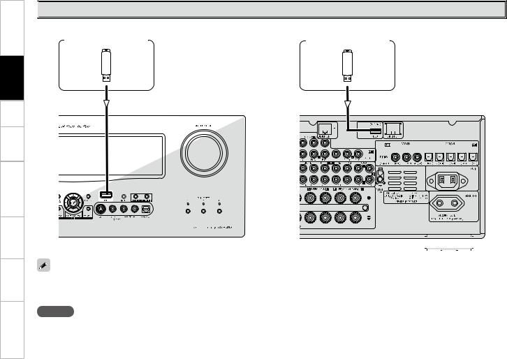
Troubleshooting Information Zone-Multi Control Remote Playback Setup Connections Started Getting

 USB Port
n Front panel |
|
|
|
|
|
|
n Rear panel |
|
|
|
|
|
|
|
|
|
|
|
|
|
|
|
|
|
|||||||||||||||||||||||||||||
|
|
|
|
|
|
|
|
|
|
|
|
|
|
|
|
|
|
|
|
|
|
|
|
|
|
|
|
|
|
|
|
|
|
|
|
|
|
|
|
|
|||||||||||||
|
|
USB memory device |
|
|
|
|
|
|
|
|
|
|
USB memory device |
|
|
|
|
|
|
|
|
|
|
|
|
|
|
|
|
|
|||||||||||||||||||||||
|
|
|
|
|
|
|
|
|
|
|
|
|
|
|
|
|
|
|
|
|
|
|
|
|
|
|
|
|
|
|
|
|
|
|
|
|
|
|
|
|
|
|
|
|
|
|
|
|
|
|
|
|
|
|
|
|
|
|
|
|
|
|
|
|
|
|
|
|
|
|
|
|
|
|
|
|
|
|
|
|
|
|
|
|
|
|
|
|
|
|
|
|
|
|
|
|
|
|
|
|
|
|
|
|
|
|
|
|
|
|
|
|
|
|
|
|
|
|
|
|
|
|
|
|
|
|
|
|
|
|
|
|
|
|
|
|
|
|
|
|
|
|
|
|
|
|
|
|
|
|
|
|
|
|
|
|
|
|
|
|
|
|
|
|
|
|
|
|
|
|
|
|
|
|
|
|
|
|
|
|
|
|
|
|
|
|
|
|
|
|
|
|
|
|
|
|
|
|
|
|
|
|
|
|
|
|
|
|
|
|
|
|
|
|
|
|
|
|
|
|
|
|
|
|
|
|
|
|
|
|
|
|
|
|
|
|
|
|
|
|
|
|
|
|
|
|
|
|
|
|
|
|
|
|
|
|
|
|
|
|
|
|
|
|
|
|
|
|
|
|
|
|
|
|
|
|
|
|
|
|
|
|
|
|
|
|
|
|
|
|
|
|
|
|
|
|
|
|
|
|
|
|
|
|
|
|
|
|
|
|
|
|
|
|
|
|
|
|
|
|
|
|
|
|
|
|
|
|
|
|
|
|
|
|
|
|
|
|
|
|
|
|
|
|
|
|
|
|
|
|
|
|
|
|
|
|
|
|
|
|
|
|
|
|
|
|
|
|
|
|
|
|
|
|
|
|
|
|
|
|
|
|
|
|
|
|
|
|
|
|
|
|
|
|
|
|
|
|
|
|
|
|
|
|
|
|
|
|
|
|
|
|
|
|
|
|
|
|
|
|
|
|
|
|
|
|
|
|
|
|
|
|
|
|
|
|
|
|
|
|
|
|
|
|
|
|
|
|
|
|
|
|
|
|
|
|
|
|
|
|
|
|
|
|
|
|
|
|
|
|
|
|
|
|
|
|
|
|
|
|
|
|
|
|
|
|
|
|
|
|
|
|
|
|
|
|
|
|
|
|
|
|
|
|
|
|
|
|
|
|
|
|
|
|
|
|
|
|
|
|
|
|
|
|
|
|
|
|
|
|
|
|
|
|
|
|
|
|
|
|
|
|
|
|
|
|
|
|
|
|
|
|
|
|
|
|
|
|
|
|
|
|
|
|
|
|
|
|
|
|
|
|
|
|
|
|
|
|
|
|
|
|
|
|
|
|
|
|
|
|
|
|
|
|
|
|
|
|
|
|
|
|
|
|
|
|
|
|
|
|
|
|
|
|
|
|
|
|
|
|
|
|
|
|
|
|
|
|
|
|
|
|
|
|
|
|
|
|
|
|
|
|
|
|
|
|
|
|
|
|
|
|
|
|
|
|
|
|
|
|
|
|
|
|
|
|
|
|
|
|
|
|
|
|
|
|
|
|
|
|
|
|
|
|
|
|
|
|
|
|
|
|
|
|
|
|
|
|
|
|
|
|
|
|
|
|
|
|
|
|
|
|
|
|
|
|
|
|
|
|
|
|
|
|
|
|
|
|
|
|
|
|
|
|
|
|
|
|
|
|
|
|
|
|
|
|
|
|
|
|
|
|
|
|
|
|
|
|
|
|
|
|
|
|
|
|
|
|
|
|
|
|
|
|
|
|
|
|
|
|
|
|
|
|
|
|
|
|
|
|
|
|
|
|
|
|
|
|
|
|
|
|
|
|
|
|
|
|
|
|
|
|
|
|
|
|
|
|
|
|
|
|
|
|
|
|
|
|
|
|
|
|
|
|
|
|
|
|
|
|
|
|
|
|
|
|
|
|
|
|
|
|
|
|
|
|
|
|
|
|
|
|
|
|
|
|
|
|
|
|
|
|
|
|
|
|
|
|
|
|
|
|
|
|
|
|
|
|
|
|
|
|
|
|
|
|
|
|
|
|
|
|
|
|
|
|
|
|
|
|
|
|
|
|
|
|
|
|
|
|
|
|
|
|
|
|
|
|
|
|
|
|
|
|
|
|
|
|
|
|
|
|
|
|
|
|
|
|
|
|
|
|
|
|
|
|
|
|
|
|
|
|
|
|
|
|
|
|
|
|
|
|
|
|
|
|
|
|
|
|
|
|
|
|
|
|
|
|
|
|
|
|
|
|
|
|
|
|
|
|
|
|
|
|
|
|
|
|
|
|
|
|
|
|
|
|
|
|
|
|
|
|
|
|
|
|
|
|
|
|
|
|
|
|
|
|
|
|
|
|
|
|
|
|
|
|
|
|
|
|
|
|
|
|
|
|
|
|
|
|
|
|
|
|
|
|
|
|
|
|
|
|
|
|
|
|
|
|
|
|
|
|
|
|
|
|
|
|
|
|
|
|
|
|
|
|
|
|
|
|
|
|
|
|
|
|
|
|
|
|
|
|
|
|
|
|
|
|
|
|
|
|
|
|
|
|
|
|
|
|
|
|
|
|
|
|
|
|
|
|
|
|
|
|
|
|
|
|
|
|
|
|
|
|
|
|
|
|
|
|
|
|
|
|
|
|
|
|
|
|
|
|
|
|
|
|
|
|
|
|
|
|
|
|
|
|
|
•In the initial status, USB memory devices can be used by connecting them to the USB port on the front panel.
•To change the port to be used, see “USB Select” on page 40.
•For instructions on playing the files on a USB memory device, see page 56.
NOTE
•Set to the USB port you want to use.
•The AVR-3808 is equipped with two USB ports, one each on the front and rear panels. It is not possible to use the set with USB memory devices connected to both the ports at the same time. Select the USB port you want to use at the GUI menu “Source Select” – “NET/USB” – “Playback Mode” – “USB Select”.
•Do not use the extension cable for connecting the USB memory deveice to the AVR-3808’s USB port. Use of the extension cable may cause harmful interference.
18

 Antenna terminals
An FM antenna cable plug can be connected directly.
Direction of broadcasting station
FM antenna |
AM loop antenna |
|
(supplied) |
||
|
||
75 Ω/ohms |
|
|
Coaxial cable |
|
|
FM indoor antenna |
|
|
(supplied) |
|
Ground |
AM outdoor antenna |
|
AM loop antenna assembly
Remove the vinyl tie and take out the connection line.
a.With the antenna on top of any stable surface.
Mount
Connect to the AM antenna terminals.
Bend in the reverse direction.
b.With the antenna attached to a wall.
Installation hole Mount on wall, etc.
Connection of AM antennas
1. Push the |
2. Insert the |
3. Return the |
||||||||
lever. |
conductor. |
lever. |
||||||||
|
|
|
|
|
|
|
|
|
|
|
|
|
|
|
|
|
|
|
|
|
|
NOTE
•Do not connect two FM antennas simultaneously.
•Even if an external AM antenna is used, do not disconnect the AM loop antenna.
•Make sure the AM loop antenna lead terminals do not touch metal parts of the panel.
Troubleshooting Information Zone-Multi Control Remote Playback Setup Connections Started Getting
19

Troubleshooting Information Zone-Multi Control Remote Playback Setup Connections Started Getting

 Network Audio
Computer
Modem
Internet |
|
|
To WAN side |
|
|
To LAN port |
|
|
To LAN port |
LAN port/ |
|
Ethernet |
||
|
||
|
connector |
|
Router |
|
Required system
n Broadband Internet connection
A broadband line connection to the Internet is required in order to use the AVR-3808’s Internet radio function and firmware update.
n Modem
This is a device that is connected to the broadband line to communicate with the Internet. Some are integrated with the router.
n Router
When using the AVR-3808, we recommend you use a router equipped with the following functions:
•Built-in DHCP (Dynamic Host Configuration Protocol) server This function automatically assigns IP addresses on the LAN.
•Built-in 100BASE-TX switch
When connecting multiple devices, we recommend a switching hub with a speed of 100 Mbps or greater.
nEthernet cable (CAT-5 or greater recommended)
•The AVR-3808 does not come with an Ethernet cable.
•Some flat type Ethernet cables are easily affected by noise. We recommend using a normal type cable.
•For the Ethernet cable, used a shielded twisted pair (STP) cable. Do not use an unshielded twisted pair (UTP) cable, as it may exceed noise standard limits.
n Computer
A computer with the following specifications is required to use a music server:
•OS
Windows® XP Service Pack2, Windows Vista
•Software (Prepare one of the following.)
·.NET Framework 1.1 and Windows Media Connect (Windows XP)
·Windows Media Player ver.11
·DLNA-compatible server software
•Internet browser
Microsoft Internet Explorer 5.01 or later
•LAN port
•300 MB or more free disk space
b Free disk space is required to store music files. The following sizes are approximate.
Format |
Bit rate |
Per minute |
Per hour |
|
|
|
|
MP3 / WMA |
128 kbps |
Approx. 1 MB |
Approx. 60 MB |
192 kbps |
Approx. 1.5 MB |
Approx. 90 MB |
|
MPEG-4 AAC |
256 kbps |
Approx. 2 MB |
Approx. 120 MB |
|
392 kbps |
Approx. 3 MB |
Approx. 180 MB |
WAV (LPCM) |
1400 kbps |
Approx. 10 MB |
Approx. 600 MB |
FLAC |
1080 kbps |
Approx. 7.7 MB |
Approx. 464 MB |
For connections to the Internet, contact an ISP (Internet Service Provider) or a computer shop.
NOTE
•A contract with an ISP is required to connect to the Internet.
No additional contract is needed if you already have a broadband connection to the Internet.
•The types of routers that can be used depend on the ISP. Contact an ISP or a computer shop for details.
•Depending on the server, video files may be displayed, but they cannot be played on the AVR-3808.
nOthers
•If you have an Internet provider contract for a line on which network settings are made manually, make the settings at GUI menu “Manual Setup” – “Network Setup” (vpage 32, 33).
•With the AVR-3808, it is possible to use the DHCP and Auto IP functions to make the network settings automatically.
•When using a broadband router (DHCP function), the AVR-3808 sets the IP address, etc., automatically.
When using the AVR-3808 connected to a network with no DHCP function, make the settings for the IP address, etc., at GUI menu “Manual Setup” – “Network Setup” (vpage 32, 33).
•The AVR-3808 is not compatible with PPPoE. A PPPoE-compatible router is required if you have a contract for a line of the type with which the PPPoE is set.
•Depending on the ISP with which you have your contract, it may be necessary to make proxy server settings to use the Internet radio function. If you made proxy server settings on the computer to connect to the Internet, make the proxy server settings on the AVR-3808 in the same way.
20

|
Multi-Zone |
|
External Controller |
ZONE2 or ZONE3 Pre-out Connections
•If another power amplifier or pre-main (integrated) amplifier is connected, the ZONE2 or ZONE3 pre-out
(variable or fixed level) connectors can be used to play a different program source in ZONE2 or ZONE3 the same time (vpage 69 ~ 72).
•When using an S-Video cable or a video cable for connection between the AVR-3808 and an input device, connect to the video connectors.
•The ZONE2 video out is only for ZONE2.
Monitor (ZONE2) |
Power amplifier |
|
(ZONE2 or ZONE3) |
||
7*%&0 |
"6%*0 |
|
7*%&0 |
"6%*0 |
|
*/ |
|
*/ |
|
- |
3 |
|
L |
R |
RS-232C connector
This connector is used for an external controller.
b If you wish to control the AVR-3808 from an external controller using the RS-232C connector, perform the operation below beforehand.
q Turn the AVR-3808’s power.
w Turn off the AVR-3808’s power from the external controller.
e Check that the AVR-3808 is in the standby mode.
L |
R |
"69 |
Input |
|
|
065 |
Output |
|
|
|
|
Extension jack for future use. |
|
Infrared |
|
Infrared |
|
retransmitter |
|
sensor |
|
NOTE
•For the audio output, use high quality pin-plug cords so that no induction humming or noise is produced.
•For instructions on installing and operating separately sold devices, refer to the respective devices’ operating instructions.
•To conduct multi-zone playback, see “Amp Assign / Multi-Zone Connections and Operations” (vpage 69 ~ 72).
•When using in combination with an RF Remote Controller (RC-7000CI, sold separately) or RF Remote Receiver (RC-7001RCI, sold separately) two-way communication with an RF Remote Controller is possible.
The AVR-3808’s status information as well as iPod and Internet audio music files can be browsed watching the RF Remote Controller’s display. For details, refer to the operating instructions of the respective devices.
•When used in combination with an RF Remote Controller or RF Remote Receiver, make the settings at GUI menu “Manual Setup” – “Option Setup” – “2Way Remote” – “Used” (vpage 35).
Trigger output jacks
The power of an external device equipped with a trigger input jack can be turned on and off in association with operations on the AVR-3808. For details, see GUI menu “Manual Setup” – “Option Setup” – “Trigger Out 1” or “Trigger Out 2” (vpage 35).
• Output level: 150 mA/12 V
Check the trigger input conditions of the connected device.
• If the trigger input level of the connected device is higher than 150 mA/12 V and depending on the short-circuiting conditions, the AVR-3808’s protection circuit may be activated, in which case “TRIGGER PROTECT” appears on the display. If this happens, turn off the AVR-3808’s power and disconnect the connected device.
Troubleshooting Information Zone-Multi Control Remote Playback Setup Connections Started Getting
21

Connecting the Power Cord
Wait until all connections have been completed before connecting the power cord.
|
To household |
|
Power cord |
power outlet |
|
(AC 230 V, 50 Hz) |
||
(included) |
||
|
GUI Menu Operations
With the AVR-3808, settings and operations for most functions can be performed by operating while looking at the GUI menus displayed on the monitor screen.
Connection to the AC outlet
• This outlet supply power to external audio 
 devices.
• The power supplied from these outlets turns on and off together with the set’s power switch.
• Audio equipment with a total power consumption of 100 W (0.43 A) can be connected.
NOTE
•Insert the AC plugs securely. Incomplete connections could cause noise.
•Only use the AC outlet to plug in audio devices. Do not use them as power supplies for hairdryers or anything other than audio equipment.
Once Connections are Completed
The GUI cannot be superimposed when xvYCC signals and component 1080p signal, computer’s resolution (e.g. VGA) are input.
Example of the Display of the GUI Mark at a Title
Auto Setup
Optimize settings for speakers in use. The appropriate settings for the speakers you are using will be performed automatically.
Operate as instructed on the GUI.
Example of Display of Default Values
[Selectable items] |
|
|
7.1 |
|
5.1 |

Examples of GUI Screen Displays
Some typical examples are described below.
n Icon
PHONO
CD
DVD
HDP
TV/CBL
 settings
|
|
|
|
|
|
|
|
|
|
|
n List |
|
|
|
|
|
|
|
|
|
|
|
Assign |
|
|
|
|
|
|
|
|
|
|
|
|
|
|
|
|
|
|
|
|
|
|
|
Input Mode |
|
|
|
|
|
|
|
|
|
|
|
|
|
|
|
|
|
|
|
|
|
|
|
|
|
|
|
|
|
|
|
|
|
|
|
Rename |
|
|
|
|
|
|
|
|
|
|
||
|
|
|
AUTO SETUP |
1 2 3 |
4 5 |
|
Other |
||||
|
|
|
|||||||||
|
STEP1 Speaker Detection |
|
|
||||||||
|
Please place the microphone at ear |
|
|
|
|
|
|||||
|
height at main listening position. |
|
|
|
|
|
|||||
|
|
|
Start |
|
|
|
|
|
|||
|
|
Config. 7.1(B) |
|
|
|
|
|
||||
|
|
Amp Assign |
|
|
|
|
|
||||
|
|
|
|
Enter |
|
Cancel |
|
|
|||
|
Start Auto Setup |
|
|
|
|
|
|||||
|
|
|
|
|
|
|
|
|
|
|
|
|
|
|
|
|
|
|
|
|
|
|
|
|
|
|
|
|
|
|
|
|
|
|
|
|
|
|
|
|
|
|
|
|
|
|
|
Operations
The same operation is possible on the main unit or remote control unit.
1Press the MENU button.
The GUI menu is displayed.
b To operate from the main remote control unit, be sure to set the remote control unit to the AMP mode.
2Press the u i pbutton to select the menu to be set or operated.
b To return to the previous item, press the o or RETURN button.
3Press the ENTER button to enter the setting.
4Press the MENU button to finish.
When “Screensaver” is set to “ON”, the screensaver is activated if no operation is performed for about 3 minutes.
b Switch the selected item using ui.

GUI Menu Map
nStatus
•MAIN ZONE
•ZONE2/3
n Audio Input Signal
n HDMI Information
n Auto Surround Mode
n Quick Select
n Preset Station
nAudio
•Surround Parameters
·Mode
·Cinema EQ
·DRC
·D.COMP
·LFE
·Center Image
·Panorama
·Dimension
·Center Width
·DelayTime
·Effect
·Effect Level
·Room Size
·AFDM
·SB CH Out
·Subwoofer Att.
·Subwoofer
·Default
•Tone
·Tone Defeat
·Bass
·Treble
•Room EQ
•RESTORER
•Night Mode
•Audio Delay
nPicture Adjust
•Contrast
•Brightness
•Chroma Level
•Hue
n TUNER (FM/AM)
•Play
•Auto Preset
•Preset Skip
•Preset Name
•Input Mode
•Rename
•Other
·Video Select
·Source Level
n STEREO n DIRECT
n STANDARD
n DOLBY PLIIx, DOLBY PLII or
DOLBY PL n DTS NEO:6
n 7CH STEREO n WIDE SCREEN
n SUPER STADIUM n ROCK ARENA
n JAZZ CLUB
n CLASSIC CONCERT n MONO MOVIE
n VIDEO GAME n MATRIX
n VIRTUAL
n PHONO |
n CD, DVD, HDP,TV/CBL, |
n NET/USB |
• Input Mode |
SAT,VCR, DVR,V.AUX |
• Play |
• Rename |
• Play (iPod) |
• Playback Mode |
• Other |
• Playback Mode (iPod) |
• Input Mode |
· Video Select |
• Assign |
• Rename |
· Source Level |
• Input Mode |
• Other |
|
• Rename |
· Video Select |
|
• Other |
· Source Level |
· Video Select
· Video Convert (Excluding CDs)
· Source Level
n Auto Setup |
n Option |
n Parameter |
• STEP1: Speaker Detect |
• Room EQ |
• Speaker Configuration Check |
• STEP2: Measurements |
• Direct Mode |
• Distance Check |
• STEP3: Calculation |
• Mic Select |
• Channel Level Check |
• STEP4: Check |
|
• Crossover Check |
• STEP5: Store |
|
• EQ Check |
|
|
• Restore |
n Speaker Setup (vpage 28, 29) |
n Network Setup (vpage 32, 33) |
n Option Setup (vpage 34 ~ 36) |
• Speaker Configuration |
• Network Setup |
• Amp Assign |
• Subwoofer Mode |
• Other |
• Volume Control |
• Distance |
· Power Saving |
· Volume Limit |
• Channel Level |
· Character |
· Power On Level |
• Crossover Frequency |
· PC Language |
· Mute Level |
• Surround Speaker |
• Network Information |
• Source Delete |
n HDMI Setup (vpage 30) |
n Zone Setup (vpage 33) |
• GUI |
• i/p Scaler |
• ZONE2 |
· Screensaver |
• Resolution |
· Bass |
· Wall Paper |
• Progressive Mode |
· Treble |
· Format |
• Aspect |
· HPF |
· Text |
• Color Space |
· Lch Level |
· Master Volume |
• RGB Range |
· Rch Level |
· NET/USB |
• Auto Lip Sync |
· Channel |
· iPod |
• Audio |
· Volume Level |
· Tuner |
n Audio Setup (vpage 30, 31) |
· Volume Limit |
• Quick Select Name |
• EXT. IN Setup |
· Power On Level |
• Trigger Out 1 |
· Surround Speaker |
· Mute Level |
• Trigger Out 2 |
· Subwoofer Level |
• ZONE3 |
• Remote ID |
• 2ch Direct/Stereo |
· Bass |
• 2Way Remote |
• Downmix Option |
· Treble |
• Dimmer |
• Auto Surround |
· HPF |
• Setup Lock |
• Manual EQ |
· Lch Level |
• Maintenance Mode |
|
· Rch Level |
• Firmware Update |
|
· Channel |
n Language (vpage 36) |
|
· Volume Level |
|
|
· Volume Limit |
|
|
· Power On Level |
|
|
· Mute Level |
|

|
Preparations |
|
Connect the included calibrated setup microphone to |
Auto Setup |
1the SETUP MIC jack on the main unit. |
The auto setup screen appears automatically. |
•Audyssey MultEQ® XT automatically measures the acoustical problems in the listening environment to create the best audio experience for your home theater.
•It optimizes a large listening area where one or more listeners are seated.
Measurements are performed by placing the calibrated microphone (DM-A405) successively at multiple positions throughout the listening area as shown in Example q. For best results, it is strongly recommended to measure 6 or more positions so that the measurements have the proper spatial weighting.
Even if the listening environment is small as shown in Example w, measuring at multiple points throughout the listening environment results in more effective correction.
Example q |
Example w |
( :Measuring positions) |
|
*M |
*M |
Sound 


 receptor

2Place the microphone at ear height on a tripod or stand with the microphone pointing directly up towards the ceiling.
Setup

 microphone

b It is not recommended to hold it in your hand. Be sure that the path from microphone to the speakers is not blocked by objects. Avoid placing the microphone close to a seat back or wall as sound reflections may give inaccurate results.
About the main listening position (*M)
The main listening position refers to the most central position where one would normally sit within the listening environment.
MultEQ XT uses the measurements from this position to calculate speaker distance, level, polarity, and the optimum crossover value for the subwoofer.
To make manual adjustments to the settings, see pages 28, 29.
When using a subwoofer, make the following settings before starting the auto setup procedure:
•Defeat the volume and crossover controls if possible
•If this is not possible then set
•Volume: “12 o’clock” position
•Crossover frequency: “Maximum/Highest Frequency”
•Low pass fi lter: “Off”
•Standby mode: “Off”
NOTE
•Do not disconnect the setup microphone until the auto setup procedure is completed.
•When using headphones, unplug the headphones before starting the auto setup procedure.
Auto Setup
Optimize settings for speakers in use.
F Menu tree F
Start
Start Auto Setup.
The Audyssey MultEQ XT Auto Setup process automatically calculates the size, level, distance, bass management crossover frequency, and optimal settings for each speaker and subwoofer. Audyssey MultEQ XT corrects acoustical distortions within the listening area.
Before starting, connect and position all your speakers.
Once started, MultEQ XT will play a series of test tones through each speaker.
If an error message appears during the measurements, check “Error Messages” (vpage 27), take the advised action, then start the measurements again.
Configuration
The speaker system to be measured can be selected ahead of time here.
[Selectable items] |
|
|
7.1 |
|
5.1 |
Setting the correct speaker confi guration can reduce the time required to measure during the auto setup procedure as the system will not have to look for speakers that are not connected.
Amp Assign
Advanced setting : changes power amplifier assignment.
NOTE
The items selectable at “Confi g.” differ according to the “Amp Assign” settings.
The speaker connection and polarity are detected at the fi rst measurement position. The following attributes are also determined at this time: “Speaker Size”, “Speaker Distance”, “Channel Level”, “Crossover Frequency”.
Once the measurements are completed, the results are displayed.
NOTE
•Loud test tone may be played during Audyssey MultEQ XT Automatic Speaker Setup.This is part of normal operation. If there is background noise in room, these test tones will increase in volume.
•Do not stand between the speakers and setup microphone or allow obstacles in the path while the measurements are being made. This will cause inaccurate readings.
•Quiet the listening environment before beginning measurements and refrain from talking. Turn off air conditioning units or other devices that emit noise if at all possible as measurements may be affected by these sounds.
•Operating the MASTER VOLUME knob on the main unit or the VOL +/– buttons on the remote control unit during the measurements will cancel the measurements.
•Do not change the speaker connections or subwoofer volume after “STEP1”.
After completing a measurement position, move the microphone to the next position.
Measure at least 6 positions (main listening position and at least 5 other surrounding positions). For best results it is recommend measuring 6 or more positions (with a maximum of 8 positions).
When “Calculate” is selected at “STEP2”, the measurements taken are analyzed automatically to determine how the speaker system interacts with the room.
The time required for this analysis depends on the number of speakers connected. The higher the number of speakers, the longer the time required for analysis.
Once the auto setup procedure is complete, a measuring result check screen appears.
Select any item whose results you want to check to review the results.
Values that are different from the actual distance may be set for speakers with built-in fi lters (subwoofers, etc.). This is because fi lters add electrical delay to the signal that should be compensated.
The auto setup measurement results are stored in the AVR-3808.
NOTE
Do not turn the power off while the settings are being stored.

|
|
|
Error messages (examples) |
Cause |
Measures |
No microphone or speaker |
• Included setup microphone is not connected. |
• Connect the included setup microphone to the SETUP MIC |
|
|
jack on the main unit. |
|
• Not all speakers could be detected. |
• Check the speaker connections. |
Ambient noise is too high |
• Too much noise in the room for accurate • Either turn off any device generating noise or move it |
|
or Level is too low |
measurements to be made. |
away. |
|
|
• Try again when the surroundings are quieter. |
|
• Speaker or subwoofer sound is too low |
for • Check the speaker installation and the direction in which |
|
accurate measurements to be made. |
the speakers are facing. |
|
|
• Adjust the subwoofer’s volume. |
None |
• Displayed speaker could not be detected. |
• Check the connections of the displayed speaker. |
·The front L and front R speakers were not properly detected.
·Only one channel of the surround (A) and surround (B) speakers was detected.
·Sound was output from the R channel when only one surround back speaker was connected.
·The surround back or the surround (B) speaker was detected, but the surround (A) speaker was not detected.
Phase |
• Displayed speaker connected with the polarities • Check the polarities of the displayed speaker. |
|
|
reversed. |
• For some speakers, this error message may be displayed |
|
|
even if the speaker is properly connected. If you are sure |
|
|
that the wiring is correct, select “Skip”. |
 Select “Retry” to make the measurements again.
NOTE Be sure to turn the power off before checking the speaker connections.
Room EQ
Select room EQ setting method.
[Selectable items]  Assign
Direct Mode
Select room EQ use for DIRECT or PURE DIRECT mode.
[Selectable items] ON
Mic Select
Select the microphone type if not using supplied mic. The microphone connected to V.AUX Lch is used.
[Selectable items]  V.AUX L
A professionally-calibrated microphone may be used by connecting it to the V.AUX L input on the front panel. This is not recommended as there is no calibration curve applied to the external mic input.
|
|
|
|
|
|
|
|
|
|
|
|
|
|
|
|
|
|
|
|
|
|
|
|
|
|
|
|
|
|
|
|
|
|
|
|
|
|
|
[Items to be checked] |
Spkr Config Check |
|
|
Distance Check |
|
|||||||
|
|
|
|
|
|
|
||||||
|
|
Ch. Level Check |
|
|
Crossover Check |
|
||||||
|
|
|
|
|
|
|
|
|
|
|||
|
|
EQ Check |
|
|
|
|
|
|
|
|
||
|
|
|
|
|
|
|
|
|
|
|
|
|
The auto setup results can be reset to what was originally calculated by MultEQ XT when “Restore” is selected.

Manual Setup
Make detail settings for various parameters.
Speaker Setup
Use this procedure to set the speakers manually or if you wish to change the settings made with the auto setup procedure.
F Menu tree F
Front
Select front speaker size.
[Selectable items]  Small
Small
Center
Select center speaker use and size.
[Selectable items] |
Large |
|
|
|
None |
Subwoofer
Select subwoofer use.
[Selectable items]  No
No
Surround A
Select surround speakers A use and size.
|
[Selectable items] |
Large |
|
|
|
None |
|
||||||
|
|
|
|
|
|
|
Surround B
Select surround speakers B use and size.
[Selectable items] |
Large |
|
|
|
None |
Surround Back
Select surround back speaker use and size.
[Selectable items] |
Large |
|
|
|
|
None |
|
|
|
|
|
|
|
|
|
|
|
1spkr |
|
|
|
|
|
|
|
|
|
Large : Select this for a large speaker with strong bass reproduction.
Small : Select this for a smaller speaker with weaker bass reproduction.
•Select “Large” or “Small” not according to the physical size of the speaker but according to the low frequency reproduction capabilities based on the frequency set at “Crossover Frequency” (vpage 29).
•When “Front” is set to “Small”, “Subwoofer” is automatically set to “Yes”.
•If “Subwoofer” is set to “No”, “Front” is automatically set to “Large”.
•If “Surround A” is set to “None”, “Surround B” and “Surround Back” are automatically set to “None”.
•When using just one surround back speaker, connect it to the left channel (SBL).
[Selectable items]  LFE+Main
•This can be set when GUI menu “Speaker Confi guration” – “Subwoofer” is set to “Yes”.
•Play music or a movie source and select the mode offering the strongest bass.
•Select “LFE+Main” if you want the bass signals to always be produced from the subwoofer.
Meters / Feet
Select unit for distance.
Step
Select step. (smallest distance)
[Selectable items]
0.01m : Can be selected when “Meters” is set.
0.1ft : Can be selected when “Feet” is set.
Default
Resets the settings to the default values.
Distance measurement
Select the speaker you want to set, then set the distance. Set the value closest to the measured distance.
[Variable range]
0.00m ~ 18.00m : Display when “Meters” is set.
0.0ft ~ 60.0ft : Display when “Feet” is set.
NOTE
Set the distance between the listening position and the various speakers to no more than 6.00 meters (20.0 ft).
 Loading...