


Dell™ Latitude™ E6510 Service Manual
Working on Your Computer
Removing and Replacing Parts
Specifications
Diagnostics
System Setup
Notes, Cautions, and Warnings
NOTE: A NOTE indicates important information that helps you make better use of your computer.
CAUTION: A CAUTION indicates potential damage to hardware or loss of data if instructions are not followed.
WARNING: A WARNING indicates a potential for property damage, personal injury, or death.
If you purchased a Dell™ n Series computer, any references in this document to Microsoft® Windows® operating systems are not applicable.
Information in this document is subject to change without notice.
© 2010 Dell Inc. All rights reserved.
Reproduction of this material in any manner whatsoever without the written permission of Dell Inc. is strictly forbidden.
Trademarks used in this text: Dell, the DELL logo, Latitude ON, Latitude, and Wi-Fi Catcher are trademarks of Dell Inc.; Intel, SpeedStep, TurboBoost, and Core are either trademarks or registered trademarks of Intel Corporation; Bluetooth is a registered trademark owned by Bluetooth SIG, Inc. and is used by Dell under license;
Blu-ray Disc is a trademark of the Blu-ray Disc Association; Microsoft, Windows, Windows Vista, and the Windows Vista start button are either trademarks or registered trademarks of Microsoft Corporation in the United States and/or other countries; Adobe, the Adobe logo, and Adobe Flash Player are trademarks of Adobe Systems Incorporated.
Other trademarks and trade names may be used in this document to refer to either the entities claiming the marks and names or their products. Dell Inc. disclaims any proprietary interest in trademarks and trade names other than its own.
June 2010 |
Rev. A00 |
Back to Contents Page
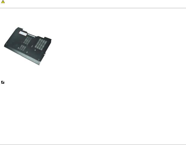
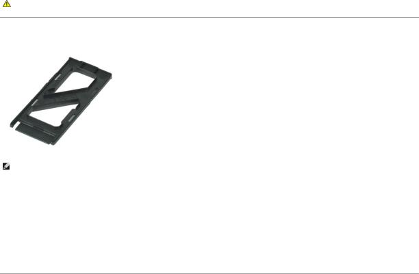
Access Panel
Dell™ Latitude™ E6510 Service Manual
WARNING: Before working inside your computer, read the safety information that shipped with your computer. For additional safety best practices information, see the Regulatory Compliance Homepage at www.dell.com/regulatory_compliance.
Removing the Access Panel
NOTE: You may need to install Adobe™ Flash Player™ from Adobe.com in order to view the illustrations below.
1.Follow the procedures in Before Working Inside Your Computer.
2.Loosen the captive screw that secures the access panel to the base of the computer.
3.Slide the access panel towards the front of the computer.
4.Lift the access panel up and away from the computer.
Replacing the Access Panel
To replace the access panel, perform the above steps in reverse order.
Back to Contents Page
Back to Contents Page
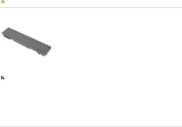
Battery
Dell™ Latitude™ E6510 Service Manual
WARNING: Before working inside your computer, read the safety information that shipped with your computer. For additional safety best practices information, see the Regulatory Compliance Homepage at www.dell.com/regulatory_compliance.
Removing the Battery
NOTE: You may need to install Adobe™ Flash Player™ from Adobe.com in order to view the illustrations below.
1.Follow the procedures in Before Working Inside Your Computer.
2.Slide the battery release latches to the unlock position.
3.Slide and remove the battery from the computer.
Replacing the Battery
To replace the battery, perform the above steps in reverse order.
Back to Contents Page
Back to Contents Page
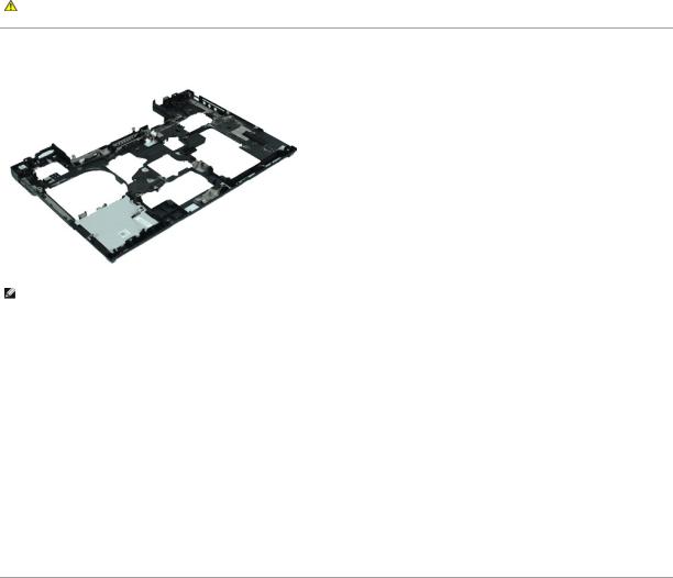
Bottom Chassis Assembly
Dell™ Latitude™ E6510 Service Manual
WARNING: Before working inside your computer, read the safety information that shipped with your computer. For additional safety best practices information, see the Regulatory Compliance Homepage at www.dell.com/regulatory_compliance.
Removing the Bottom Chassis Assembly
NOTE: You may need to install Adobe™ Flash Player™ from Adobe.com in order to view the illustrations below.
1.Follow the procedures in Before Working Inside Your Computer.
2.Remove the battery.
3.Remove the access panel.
4.Remove the subscriber identity module (SIM) card.
5.Remove the optical drive.
6.Remove the keyboard.
7.Remove the coin-cell battery.
8.Remove the hinge covers.
9.Remove the display Assembly.
10.Remove the hard drive.
11.Remove the Latitude ON™ Flash card.
12.Remove the wireless wide area network (WWAN) card.
13.Remove the wireless local area network (WLAN) card.
14.Remove the heat sink and fan assembly.
15.Remove the Processor.
16.Remove the palm rest assembly.
17.Remove the Bluetooth® card.
18.Remove the Express Card Board.
19.Remove the SD Media Board.
20.Remove the I/O Port Card.
Replacing the Bottom Chassis Assembly
To replace the bottom chassis assembly, perform the above steps in reverse order.
Back to Contents Page

Back to Contents Page
System Setup
Dell™ Latitude™ E6510 Service Manual
Overview
Entering System Setup
Boot Menu
Navigation Keystrokes
System Setup Menu Options
Overview
Use System Setup as follows:
•To change the system configuration information after you add, change, or remove any hardware in your computer
•To set or change a user-selectable option such as the user password
•To read the current amount of memory or set the type of hard drive installed
Before you use System Setup, it is recommended that you write down the System Setup screen information for future reference.
CAUTION: Unless you are an expert computer user, do not change the settings for this program. Certain changes can cause your computer to work incorrectly.
Entering System Setup
1.Turn on (or restart) your computer.
2.When the blue DELL™ logo is displayed, press <F2> immediately.
Boot Menu
The Boot menu lists all the valid boot devices for your computer. Use the Boot menu to:
•Run diagnostics on your computer
•Enter system setup
•Change the boot sequence without changing the boot sequence permanently in the system setup.
To access the Boot menu:
1.Turn on (or restart) your computer.
2.When the blue DELL™ logo is displayed, press <F12> immediately.
Navigation Keystrokes
Use the following keystrokes to navigate System Setup screens.
Navigation
Action |
Keystroke(s) |
Expand and collapse field |
<Enter>, leftor right-arrow key, or +/– |
Expand or collapse all fields |
< > |
Exit BIOS |
<Esc>—Remain in Setup, Save/Exit, Discard/Exit |
Change a setting |
Left or right-arrow key |
Select field to change |
<Enter> |
Cancel modification |
<Esc> |
Reset defaults |
<Alt><F> or Load Defaults menu option |
System Setup Menu Options
The following tables describe the menu options for the System Setup program.
General
Option |
Description |
|
|
This section lists the primary hardware features of your computer. There are no configurable options in this section. |
|
|
• |
System Information |
|
|
¡ BIOS Version |
|
|
¡ Service Tag |
|
|
¡ Asset Tag |
|
|
¡ Ownership Tag |
|
• |
Memory Information |
|
|
¡ Memory Installed |
|
|
|
¡ Memory Available |
|
|
|
¡ Memory Speed |
|
|
|
¡ Memory Channel Mode |
|
|
|
¡ Memory Technology |
|
|
|
¡ DIMM A Size |
|
|
|
¡ DIMM B Size |
|
|
• |
Processor Information |
|
|
|
¡ Processor Type |
|
|
|
¡ Core Count |
|
System Information |
|
¡ Processor ID |
|
|
¡ Current Clock Speed |
||
|
|
||
|
• |
Device Information |
|
|
|
¡ Primary Hard Drive |
|
|
|
¡ System eSATA Device |
|
|
|
¡ Dock eSATA Device |
|
|
|
¡ Video Controller |
|
|
|
¡ Video BIOS Version |
|
|
|
¡ Video Memory |
|
|
|
¡ Panel Type |
|
|
|
¡ Native Resolution |
|
|
|
¡ Audio Controller |
|
|
|
¡ Modem Controller |
|
|
|
¡ Wi-Fi Device |
|
|
|
¡ Cellular Device |
|
|
|
¡ Bluetooth Device |
|
|
|
||
Battery Information |
Displays the status of the battery and the type of AC adapter connected to the computer. |
||
|
Specifies the order in which the computer attempts to find an operating system. |
||
|
• |
Cardbus NIC |
|
|
• |
Diskette drive |
|
Boot Sequence |
• |
USB Storage Device |
|
• |
Internal HDD |
||
|
|||
|
• |
CD/DVD/CD-RW Drive |
|
|
• |
Built-in EFI shell |
|
|
• |
Onboard NIC |
|
|
|
||
Date/Time |
Displays current date and time settings. |
||
NOTE: System Configuration contains options and settings related to integrated system devices. Depending on your computer and installed devices, the items listed in this section may or may not appear.
Default setting: All enabled.
System Configuration
Option |
|
Description |
|
Integrated NIC |
|
Allows you to configure the integrated network controller. The options are: Disabled, Enabled, and Enabled w/PXE. |
|
Parallel Port |
|
Allows you to enable or disable the parallel ports on the docking station. The options are: Disabled, AT, PS2, and ECP. |
|
Serial Port |
|
Allows you to avoid resource conflicts between devices by disabling or remapping the address of the port. The options are: Disabled, |
|
|
COM1, COM2, COM3, and COM4. |
||
|
|
||
SATA Operation |
|
Allows you to configure the operating mode of the internal SATA hard drive controller. The options are: Disabled, ATA, and AHCI |
|
|
|
Allows you to enable or disable the following devices: |
|
|
|
• |
Internal Modem |
Miscellaneous |
|
• |
Module Bay |
|
• |
Express Card |
|
Devices |
|
• |
Hard Drive Free Fall Protection |
|
|
• |
External USB Port |
|
|
• |
Microphone |
|
|
• |
eSATA Ports |
|
|
• |
Media Card, PC Card and 1394 |
USB PowerShare |
|
Allows you to charge external devices using the stored system battery power through the USB PowerShare port on the notebook, |
|
|
even while the notebook is turned off. |
||
|
|
||
|
|
|
|
Video |
|
|
|
Option |
|
Description |
|
Ambient Light |
|
Allows your system to automatically change the brightness of your system's LCD panel based on the amount of light in the |
|
Sensor |
|
environment. |
|
LCD Brightness |
|
Allows you to set the display brightness depending up on the power source (On Battery and On AC). |
|
Security
Option Description
Allows you to set, change, or delete the administrator (admin) password. When set, the admin password enables several security features including:
|
• |
Restricts changes to the settings in Setup |
|
• |
Restricts the boot devices listed in the <F12> Boot Menu to those enabled in the "Boot Sequence" field |
Admin Password |
• |
Prohibits changes to the owner and asset tags |
|
• |
Substitutes for the system and hard drive password |
NOTE: You must set the admin password before you set the system or hard drive password.

|
NOTE: Successful password changes take effect immediately. |
|
|
NOTE: Deleting the admin password automatically deletes the system password as well. |
|
|
Allows you to set, change, or delete the system password. When set, your computer requests you to enter the system password every |
|
System |
time your computer turns on or restarts. |
|
Password |
|
|
|
NOTE: Successful password changes take effect immediately. |
|
Internal HDD |
This field lets you set, change, or delete the password on the system's internal hard disk drive (HDD). Successful changes take place |
|
immediately and require a system restart. The HDD password travels with the hard drive, so the HDD is protected even when installed in |
||
Password |
||
another system. |
||
|
||
|
Allows you to bypass the system and internal hard drive password prompts when your computer restarts or resumes from standby. |
|
Password |
You can set Password Bypass to: Disabled, Reboot Bypass, Resume Bypass, and Reboot & Resume Bypass. |
|
Bypass |
||
|
||
|
NOTE: You cannot bypass the system or hard drive password when you turn on your computer that has been shut down. |
|
Password |
Allows you to enable of disable changes to the System and hard drive passwords when the admin password is set. |
|
Change |
||
|
||
|
Allows you to enable or disable the Trusted Platform Module (TPM) on the computer. |
|
|
NOTE: Disabling this option does not change any settings you may have made to the TPM, or delete any information or keys you may |
|
|
have stored there. |
When TPM is enabled, the following options are available:
TPM Security
•Deactivate—Disables the TPM. The TPM restricts access to the stored owner information and does not execute any commands that use TPM resources.
•Activate—Enables and activates the TPM.
•Clear—Clears the owner information stored in the TPM.
|
Allows you to enable or disable the optional Computrace software. The options are Deactivate, Disable, and Activate. |
||||
Computrace® |
|
|
|
|
|
|
NOTE: The Activate and Disable options will permanently activate or disable the feature and no further changes will be allowed. |
||||
|
Allows you to enable or disable the Execute Disable mode of the processor. |
||||
CPU XD Support |
|
|
|
|
|
|
Default setting: Enabled |
||||
|
Determine whether changes to the setup option are permitted when an administrator password is set. If disabled the setup option is |
||||
|
locked by the admin password. It cannot be modified unless setup is unlocked. Setup is unlocked when there is no admin password, or |
||||
Non-Admin Setup when the admin password has been entered. When enabled, the device setting can be modified even when other setup options are |
|||||
Changes |
locked by the admin password. |
||||
|
Default setting: Disabled |
||||
|
|
|
|
|
|
Performance |
|
|
|
|
|
Option |
|
|
|
Description |
|
Multi Core Support |
|
Enables or disables multi-core support for the processor. |
|||
HDD Acoustic Mode |
|
Allows you to optimise the performance and acoustic noise level of the hard drive. |
|||
Intel® SpeedStep™ |
|
Enables or disables the Intel SpeedStep feature. |
|||
Intel® TurboBoost™ |
|
Enables or disables the Intel TurboBoost feature. |
|||
|
|
|
|
|
|
Power Management |
|
|
|||
|
|
|
|||
Option |
Description |
||||
Wake on AC |
Allows you to enable or disable the computer from turning on automatically when an AC adapter is connected. |
||||
|
Allows you to set the time at which the computer must turn on automatically. |
||||
Auto On Time |
You can set the of days, if any, when you would like the system to turn on automatically. The settings are Disabled, Everyday, or |
||||
Weekdays. |
|||||
|
|||||
|
Default setting: Off |
||||
|
Allows you to enable or disable the ability of USB devices to wake the computer from Standby. |
||||
USB Wake |
|
|
|
|
|
Support |
This feature is only functional when the AC power adapter is connected. If the AC power adapter is removed during Standby, the BIOS will |
||||
|
remove power from all of the USB ports to conserve battery power. |
||||
|
Allows the computer to turn on by a special LAN signal or from Hibernate state when triggered by a special wireless LAN signal. Wake-up |
||||
|
from the Standby state is unaffected by this setting and must be enabled in the operating system. |
||||
Wake on LAN |
|
• |
Disabled — Do not allow the system to power on when it receives a wake-up signal from the LAN or wireless LAN. |
||
|
|
• |
LAN Only — Allow the system to be powered on by special LAN signals. |
||
|
The factory default setting is Disabled. |
||||
ExpressCharge |
Allows you to enable or disable the ExpressCharge feature. |
||||
NOTE: ExpressCharge may not be available for all batteries. |
|||||
|
|||||
|
Allows you to enable or disable the battery charger. If disabled, the battery will not lose power when the system is connected to an AC |
||||
Charger |
adapter but it will not charge either. |
||||
Behaviour |
|
|
|
|
|
|
Default setting: Enabled |
||||
|
|
|
|
|
|
POST Behaviour |
|
|
|
|
|
|
|
|
|||
Option |
|
Description |
|||

Allows you to enable or disable the BIOS warning messages when you use certain power adapters. The BIOS displays these messages
if you attempt to use a power adapter that has too little capacity for your configuration.
Adapter Warnings
The factory default setting is Enabled.
Allows you to select one of two methods to enable the keypad that is embedded in the internal keyboard.
•Fn Key Only — The keypad is only enabled when you hold down the <Fn> key.
•By Num Lk — The keypad is enabled when (1) the Num Lock LED is on and (2) no external keyboard is attached. Note that the
Keypad |
|
system might not notice immediately when an external keyboard is detached. |
|
(Embedded) |
|
||
|
|
||
|
NOTE: When Setup is running, this field has no effect—Setup works in the Fn Key Only mode. |
||
|
Default setting: Fn Key Only. |
||
|
Determines how the system handles mouse and the touchpad input. |
||
Mouse/Touchpad |
|
|
|
|
Default setting: Touchpad/PS-2 Mouse. |
||
|
Allows you to enable or disable the Num Lock LED when the computer boots. |
||
Numlock LED |
|
|
|
|
Default setting: Enabled. |
||
|
Defines how the BIOS handles the USB devices. USB emulation is always enabled during POST. |
||
USB Emulation |
|
|
|
|
The factory default setting is Enabled. |
||
|
Allows you to use the <Scroll Lock> key on an external PS/2 keyboard the same way you use the <Fn> key on the computer's internal |
||
|
keyboard. |
||
Fn Key Emulation |
NOTE: USB keyboards cannot emulate the <Fn> key if you are running an ACPI operating system such as Microsoft® Windows® XP. |
||
|
USB keyboards will only emulate the <Fn> key in non-ACPI mode (e.g., when you are running a DOS). |
||
|
Default setting: Enabled. |
||
|
Allows you to enable or disable the Fast Boot feature. The following options are available: |
||
|
• |
Minimal — Boot quickly unless the BIOS has been updated, memory changed, or the previous POST did not complete. |
|
Fast Boot |
• |
Thorough — Do not skip any steps in the boot process. |
|
• |
Auto — Allow the operating system to control this setting (this works only when the operating system supports Simple Boot |
||
|
|||
|
|
Flag). |
|
|
Default setting: Minimal |
||
|
Used in conjunction with iAMT 4.0. Allows you to initiate contact with a management console while residing outside of the corporate |
||
Intel Fast Call for |
infrastructure (i.e. remote location, behind a firewall or NAT, etc.) Use the check box to enable / disable this feature. |
||
Help |
|
|
|
|
Default setting: Disabled |
||
Virtualization Support
Option Description
Specifies whether a Virtual Machine Monitor (VMM) can utilize the additional hardware capabilities provided by Intel Virtualization
Technology.
Virtualization
Default setting: Enabled.
Specifies whether a Virtual Machine Monitor (VMM) can utilize the additional hardware capabilities provided by Intel Virtualization
Technology for Direct I/O.
VT for Direct I/O
|
Default setting: Disabled. |
|
Specifies whether a Measured Virtual Machine Monitor(MVMM) can utilize the additional hardware capabilities provided by Intel Trusted |
Trusted |
Execution Technology. |
Execution |
|
|
Default setting: Disabled. |
|
|
Wireless |
|
Option |
Description |
Wireless Switch Allows you to choose the wireless devices that can be controlled by the wireless switch.
Wireless Devices
Allows you to enable or disable the following internal wireless devices: WWAN, WLAN, and Bluetooth.
Enable
Maintenance
Option Description
Displays your computer's Service Tag. If for some reason the Service Tag was not already set, you would be able to use this field to set it.
Service
Tag If a Service Tag has not been set for this computer, the computer will automatically bring up this screen when you enter the BIOS. You will be prompted to enter the Service Tag.
Asset Tag Allows you to create a system Asset Tag. The field can only be updated if the Asset Tag is not already set.
System Logs
Option |
Description |
|
BIOS Events |
Allows you to view and clear BIOS POST events. It includes the date and time of the event as well as the LED code. |
|
DellDiag Events |
Allows you to view the diagnostic results from Dell Diagnostics and PSA. It includes the time and date, the diagnostic and version which |
|
was run and the resulting code. |
||
|
||
|
|

Thermal Events Allows you to view and clear thermal events. It includes the date and time as well as the name of the event.
Power Events Allows you to view and clear power events. It includes the date and time of the event as well as the power state and reason.
BIOS Progress
Allows you to view and clear BIOS Progress events. It includes the date and time of the event as well as the power state.
Events
Back to Contents Page
Back to Contents Page
Bluetooth Card
Dell™ Latitude™ E6510 Service Manual
WARNING: Before working inside your computer, read the safety information that shipped with your computer. For additional safety best practices information, see the Regulatory Compliance Homepage at www.dell.com/regulatory_compliance.
Removing the Bluetooth Card
NOTE: You may need to install Adobe™ Flash Player™ from Adobe.com in order to view the illustrations below.
1.Follow the procedures in Before Working Inside Your Computer.
2.Remove the battery.
3.Remove the access panel.
4.Remove the optical drive.
5.Remove the keyboard.
6.Remove the hinge covers.
7.Remove the palm rest assembly.
8.Remove the display assembly.
9.Remove the screw that secures the Bluetooth® card to the system board.
10.Disconnect the Bluetooth cable from its connector on the system board and remove the Bluetooth card from the computer.
11.Disconnect the Bluetooth cable from the Bluetooth card.
Replacing the Bluetooth Card
To replace the Bluetooth card, perform the above steps in reverse order.
Back to Contents Page
Back to Contents Page
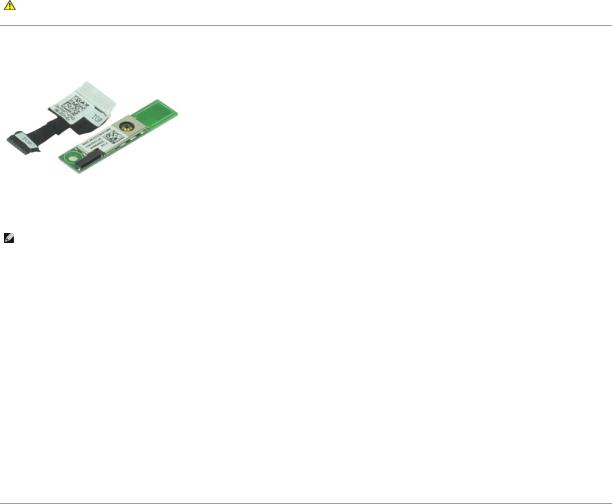
Camera and Microphone
Dell™ Latitude™ E6510 Service Manual
WARNING: Before working inside your computer, read the safety information that shipped with your computer. For additional safety best practices information, see the Regulatory Compliance Homepage at www.dell.com/regulatory_compliance.
Removing the Camera and Microphone
NOTE: You may need to install Adobe™ Flash Player™ from Adobe.com in order to view the illustrations below.
1.Follow the procedures in Before Working Inside Your Computer.
2.Remove the battery.
3.Remove the access panel.
4.Remove the hinge covers.
5.Remove the display assembly.
6.Remove the display bezel.
7.Loosen the captive screw that secures the camera and microphone to the display panel.
8.Disconnect the data cable from the camera and microphone and remove lift the camera and microphone up and away from the display panel.
Replacing the Camera and Microphone
To replace the camera and microphone, perform the above steps in reverse order.
Back to Contents Page
Back to Contents Page
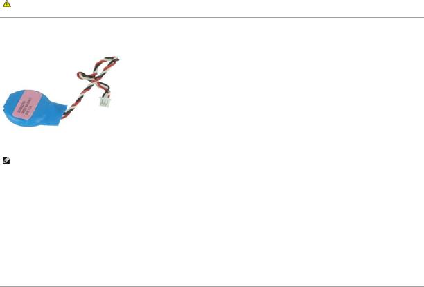
Coin-Cell Battery
Dell™ Latitude™ E6510 Service Manual
WARNING: Before working inside your computer, read the safety information that shipped with your computer. For additional safety best practices information, see the Regulatory Compliance Homepage at www.dell.com/regulatory_compliance.
Removing the Coin-Cell Battery
NOTE: You may need to install Adobe™ Flash Player™ from Adobe.com in order to view the illustrations below.
1.Follow the procedures in Before Working Inside Your Computer.
2.Remove the battery.
3.Remove the access panel.
4.Disconnect the coin-cell battery cable from its connector on the system board.
5.Lift the coin-cell battery up and away from the computer.
Replacing the Coin-Cell Battery
To replace the coin-cell battery, perform the above steps in reverse order.
Back to Contents Page
Back to Contents Page
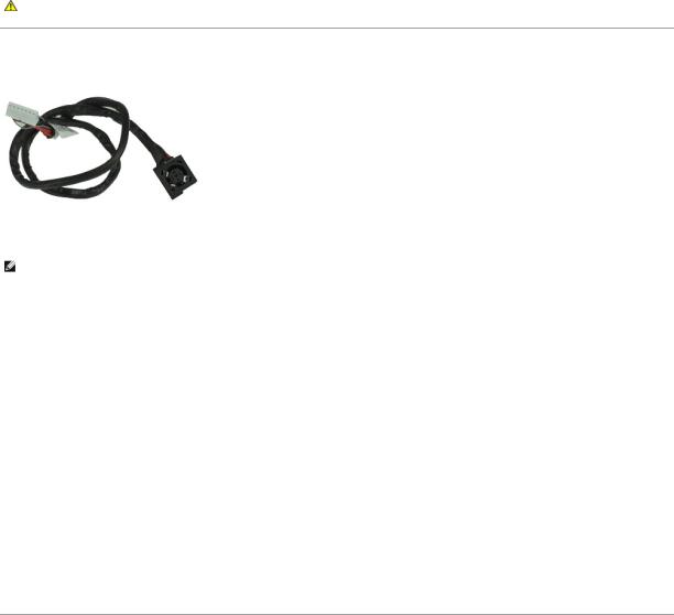
DC-In Port
Dell™ Latitude™ E6510 Service Manual
WARNING: Before working inside your computer, read the safety information that shipped with your computer. For additional safety best practices information, see the Regulatory Compliance Homepage at www.dell.com/regulatory_compliance.
Removing the DC-In Port
NOTE: You may need to install Adobe™ Flash Player™ from Adobe.com in order to view the illustrations below.
1.Follow the procedures in Before Working Inside Your Computer.
2.Remove the battery.
3.Remove the access panel.
4.Remove the subscriber identity module (SIM) card.
5.Remove the optical drive.
6.Remove the keyboard.
7.Remove the coin-cell battery.
8.Remove the hinge covers.
9.Remove the display assembly.
10.Remove the hard drive.
11.Remove the Latitude ON™ Flash card.
12.Remove the wireless wide area network (WWAN) card.
13.Remove the wireless local area network (WLAN) card.
14.Remove the heat sink and fan assembly.
15.Remove the processor.
16.Remove the palm rest assembly.
17.Remove the Bluetooth® card.
18.Remove the ExpressCard board.
19.Remove the SD card board.
20.Remove the system board.
21.Remove the I/O port card.
22.Release the DC-in port from its routing guides on the chassis.
23.Lift the DC-In port up and remove it from the chassis.
Replacing the DC-In Port
To replace the DC-In port, perform the above steps in reverse order.
Back to Contents Page
Back to Contents Page
Diagnostics
Dell™ Latitude™ E6510 Service Manual
Device Status Lights
Battery Status Lights
Battery Charge and Health
Keyboard Status Lights
LED Error Codes
Device Status Lights
Turns on when you turn on the computer and blinks when the computer is in a power management mode.
Turns on when the computer reads or writes data.
Turns on steadily or blinks to indicate battery charge status.
Turns on when wireless networking is enabled.
Turns on when a card with Bluetooth® wireless technology is enabled. To turn off only the Bluetooth wireless technology function, right-click the icon in the system tray and select Disable Bluetooth Radio.
Battery Status Lights
If the computer is connected to an electrical outlet, the battery light operates as follows:
•Alternately blinking amber light and blue light — An unauthenticated or unsupported, non-Dell AC adapter is attached to your laptop.
•Alternately blinking amber light with steady blue light — Temporary battery failure with AC adapter present.
•Constantly blinking amber light — Fatal battery failure with AC adapter present.
•Light off — Battery in full charge mode with AC adapter present.
•Blue light on — Battery in charge mode with AC adapter present.
Battery Charge and Health
To check the battery charge, press and release the status button on the battery charge gauge to illuminate the charge-level lights. Each light represents approximately 20 percent of the total battery charge. For example, if four lights are on, the battery has 80 percent of its charge remaining. If no lights appear, the battery has no charge.
To check battery health using the charge gauge, press and hold the status button on the battery charge gauge for at least 3 seconds. If no lights appear, the battery is in good condition and more than 80 percent of its original charge capacity remains. Each light represents incremental degradation. If five lights appear, less than 60 percent of the charge capacity remains, and you should consider replacing the battery.
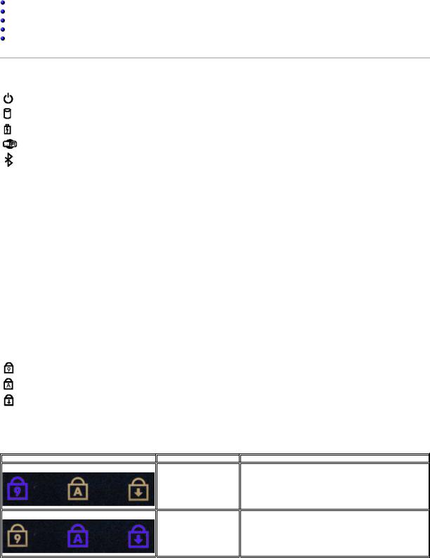
Keyboard Status Lights
The green lights located above the keyboard indicate the following:
Turns on when the numeric keypad is enabled.
Turns on when the Caps Lock function is enabled.
Turns on when the Scroll Lock function is enabled.
LED Error Codes
The following table shows the possible LED codes that may display in a no-POST situation.
Appearance
ON-FLASH-FLASH
FLASH-ON-ON
Description
No SODIMMs are installed
System board error
Next Step
1.Install supported memory modules.
2.If memory is already present, reseat the module(s) one at time in each slot.
3.Try known good memory from another computer or replace the memory.
4.Replace the system board.
1.Reseat the processor.
2.Replace the system board.
3.Replace the processor.

FLASH-ON-FLASH
OFF-FLASH-OFF
ON-FLASH-ON
OFF-FLASH-FLASH
FLASH-FLASH-FLASH
FLASH-FLASH-OFF
OFF-ON-OFF
FLASH-FLASH-ON
Display panel error
Memory compatibility error
Memory is detected but has errors
Modem error
System board error
Option ROM error
Storage device error
Video card error
1.Reseat the display cable.
2.Replace the display panel.
3.Replace the video card/system board.
1.Install compatible memory modules.
2.If two modules are installed remove one and test. Try the other module in the same slot and test. Test the other slot with both modules.
3.Replace the memory.
4.Replace the system board.
1.Reseat the memory.
2.If two modules are installed remove one and test. Try the other module in the same slot and test. Test the other slot with both modules.
3.Replace the memory.
4.Replace the system board.
1.Reseat the modem.
2.Replace the modem.
3.Replace the system board.
1. Replace the system board.
1.Reseat the device.
2.Replace the device.
3.Replace the system board.
1.Reseat the hard drive and optical drive.
2.Test the computer with just the hard drive and just the optical drive.
3.Replace the device that is causing the failure.
4.Replace the system board.
Replace the system board.
Back to Contents Page

Back to Contents Page
ExpressCard Board
Dell™ Latitude™ E6510 Service Manual
WARNING: Before working inside your computer, read the safety information that shipped with your computer. For additional safety best practices information, see the Regulatory Compliance Homepage at www.dell.com/regulatory_compliance.
Removing the ExpressCard Board
NOTE: You may need to install Adobe Flash Player from Adobe.com in order to view the illustrations below.
1.Follow the procedures in Before Working Inside Your Computer.
2.Remove the battery.
3.Remove the ExpressCard.
4.Remove the access panel.
5.Remove the optical drive.
6.Remove the keyboard.
7.Remove the hinge covers.
8.Remove the display assembly.
9.Remove the palm rest assembly.
10.Remove the screws that secure the ExpressCard board to the system board.
11.Disconnect the ExpressCard board from the system board and remove it from the computer.
Replacing the ExpressCard Board
To replace the ExpressCard board, perform the above steps in reverse order.
Back to Contents Page
Back to Contents Page
ExpressCard
Dell™ Latitude™ E6510 Service Manual
WARNING: Before working inside your computer, read the safety information that shipped with your computer. For additional safety best practices information, see the Regulatory Compliance Homepage at www.dell.com/regulatory_compliance.
Removing the ExpressCard
NOTE: You may need to install Adobe™ Flash Player™ from Adobe.com in order to view the illustrations below.
1.Press on the ExpressCard and release it from the computer.
2.Slide the ExpressCard out of the computer.
Replacing the ExpressCard
To replace the ExpressCard, perform the above steps in reverse order.
Back to Contents Page
 Loading...