


Danby DER202W User Manual

OWNER’S MANUAL
MANUAL DEL PROPIETARIO
COMPACT ELECTRIC RANGE
Owner’s Manual.............................1 - 18
ESTUFAS ELECTRICAS COMPACTAS
Manuel du propriétaire.................19 - 36
MODEL * MODELO
DER202W
DER202B
DER202BSS
www.Danby.com
DANBY PRODUCTS LIMITED, ONTARIO, CANADA N1H 6Z9
DANBY PRODUCTS INC., FINDLAY, OHIO, USA 45840
2019.02.25

Welcome
Welcome to the Danby family. We are proud of our quality products and we believe in
dependable service. We suggest that you read this owner’s manual before plugging in your new
appliance as it contains important operation information, safety information, troubleshooting and
maintenance tips to ensure the reliability and longevity of your appliance.
Visit www.Danby.com to access self service tools, FAQs and much more. For additional assistance
call 1-800-263-2629.
Note the information below; you will need this information to obtain service under warranty.
You must provide the original purchase receipt to validate your warranty and receive service.
Model Number: _________________________________________________
Serial Number: _________________________________________________
Date of Purchase: _______________________________________________
Need Help?
Before you call for service, here are a few things you can do to help us serve you better.
Read this owner’s manual:
It contains instructions to help you use and maintain your appliance properly.
If you receive a damaged appliance:
Immediately contact the retailer or builder that sold you the appliance.
Save time and money:
Check the troubleshooting section at the end of this manual before calling. This section
will help you solve common problems that may occur.
1-800-26- Danby
(1-800-263-2629)
1
Important Safety Information
READ AND FOLLOW ALL SAFETY INSTRUCTIONS
WARNING - TIP OVER HAZARD
• A child or adult can tip the appliance and be killed.
• Verify the anti-tip bracket has been properly installed and engaged to the fl oor or wall.
• Ensure the anti-tip bracket is re-engaged when the range is moved by sliding the anti-tip
arm under the bracket.
• Do not operate the range without the anti-tip bracket in place and engaged.
• Failure to follow these instructions can result in death or serious burns to children or adults.
ANTI-TIP BRACKET
To reduce the risk of the appliance tipping over, an anti-tip bracket is provided that must be installed before
operating the appliance. See installation instructions shipped with the bracket for complete details.
1. Anti-tip bracket
2. Right side panel
3. Rear wall
4. Anti-tip bracket
5. Anti-tip arm
1
2
3
4
5
To check if the bracket is installed and engaged properly, look underneath the range to see that the anti-tip
arm attached to the right side panel is engaged on the bracket. On some models, the storage drawer or
kick panel can be removed for easier inspection.
If visual inspection is not possible, slide the range forward, confi rm the anti-tip bracket is securely attached
to the fl oor or wall and slide the range back so the anti-tip arm slides under the anti-tip bracket. If the
range is pulled from the wall for any reason, always repeat this procedure to verify that the range is
properly secured by the anti-tip bracket.
SAVE THESE INSTRUCTIONS!
2

Important Safety Information
READ AND FOLLOW ALL SAFETY INSTRUCTIONS
GENERAL SAFETY REQUIREMENTS
Ensure the appliance is properly installed and
grounded by a qualifi ed technician.
Never use the appliance for warming or heating the
room.
Children should not be left alone or unattended in
the area where the appliance is in use. Children
should never be allowed to sit or stand on any part
of the appliance.
Do not store items of interest to children in cabinets
above a range or on the back guard of a range.
Children climbing on the range to reach items could
be seriously injured.
Loose fi tting or hanging garments should never be
worn while using the appliance.
Do not repair or replace any part of the appliance
unless specifi cally recommended in the manual. All
other servicing should be referred to a qualifi ed
technician.
Flammable materials should not be stored in or near
the appliance.
Do not use water on grease fi res. Smother fi re
or fl ame or use dry chemical or foam-type
extinguisher.
Use only dry pot holders. Moist or damp pot holders
on hot surfaces may result in burns from steam. Do
not let the pot holder touch hot heating elements. Do
not use a towel or other bulky cloth.
If power is lost to an electric cooktop while a surface
element is ON, the surface element will turn back on
as soon as power is restored. In the event of power
loss, failure to turn all surface element knobs to the
OFF position may result in ignition of items on or
near the cooktop, leading to serious injury or death.
To avoid the possibility of a burn or an electric
shock, always be certain that the controls for all
surface elements are at the OFF position, and that
all coils are cool before attempting to lift or remove
a coil cooking element.
COOK TOP SAFETY REQUIREMENTS
Use the proper pan size. This appliance is equipped
with four burners of different sizes. Select utensils
that have fl at bottoms large enough to cover
the surface of the heating element. The use of
undersized utensils will expose a portion of the
heating element to direct contact and may result in
ignition of clothing. Proper relationship of utensil to
burner will also improve effi ciency.
Never leave the appliance unattended while in use.
Boil over causes smoking and greasy spills can
ignite.
Never leave oil unattended while frying. If allowed
to heat beyond its smoking point, oil may ignite
resulting in fi re that may spread to surrounding
cabinets. Use a deep fat thermometer whenever
possible to monitor oil temperature.
To avoid oil spillover and fi re, use a minimum
amount of oil when shallow pan-frying and avoid
cooking frozen foods with excessive amounts of ice.
Ensure that refl ector pans or drip bowls are in
place. Absence of these pans or bowls during
cooking may subject wiring or components
underneath to damage.
Do not use aluminum foil to line drip bowls or
oven bottoms, except as suggested in the manual.
Improper installation of these liners may result in a
risk of electric shock or fi re.
Only certain types of glass, ceramic, earthenware
or other glazed utensils are suitable for range top
service without breaking due to sudden change in
temperature.
To reduce risk of burns, ignition of fl ammable
materials and spillage due to unintentional contact,
the handle of a utensil should be positioned so
that it is turned inward and does not extend over
adjacent burners.
Removable heating elements should never be
immersed in water.
SAVE THESE INSTRUCTIONS!
3

Important Safety Information
READ AND FOLLOW ALL SAFETY INSTRUCTIONS
OVEN SAFETY REQUIREMENTS
Use care when opening the door. Allow hot air or
steam to escape before removing or replacing food.
Do not heat unopened food containers. Build up of
pressure may cause the container to burst and result
in injury.
Keep oven vents unobstructed.
Always place oven racks in the desired location
while the oven is cool. If the rack must be moved
while the oven is hot, do not let the pot holder
contact the hot heating element in the oven.
Pull the oven rack to the stop-lock position when
loading and unloading food from the oven. This
helps prevent burns from touching hot surfaces of
the door and oven walls.
Do not use the oven if a heating element develops
a glowing spot during use or shows other signs
of damage. A glowing spot indicates the heating
element may fail and present a potential burn, fi re,
or shock hazard. Turn the oven off immediately and
have the heating element replaced by a qualifi ed
service technician.
WARNING - IN CASE OF FIRE
In the event of a fi re, never pick up a fl aming pot
or pan. Turn the burner off if it is safe to do so.
Extinguish the fi re with a dry chemical or foam-type
extinguisher.
Do not use water on grease fi res. Water will spread
the grease and will not extinguish the fi re. Smother
the fi re with a tight fi tting pot lid, cookie sheet or fl at
tray or use dry chemical or foam-type extinguisher.
If there is a fi re in the oven during baking, smother
the fi re by closing the oven door and turning
the oven off or use dry chemical or foam-type
extinguisher.
WARNING
To reduce the risk of burns, do not move this
appliance while it is hot. To reduce the risk of
injury due to tipping of the appliance, verify
the re-installation of this appliance into the antitipping device provided and lock the casters after
returning the appliance to the original installed
position.
DO NOT TOUCH HEATING ELEMENTS OR
AREAS NEAR THEM
Heating elements on the surface or in the interior
of the appliance may be hot even though they are
dark in colour. Areas near the heating elements
may become hot enough to cause burns. During
and after use do not touch or let clothing or other
fl ammable materials contact the heating elements
or areas near them until they have had suffi cient
time to cool. Surfaces of the appliance may
become hot enough to cause burns, among them
are the oven vent openings and surfaces near
these openings, oven doors and oven windows.
SAVE THESE INSTRUCTIONS!
4

INSTALLATION INSTRUCTIONS
BEFORE BEGINNING
Keep these instructions for future reference.
Installation of this appliance requires basic
mechanical skills and roughly 1 to 3 hours of time.
Proper installation is the responsibility of the
installer. Product failure due to improper installation
is nor covered under the warranty.
Before beginning the installation, switch power
off at the service panel and lock the service
disconnecting means to prevent power from being
switched on accidentally. If the service disconnecting
means cannot be locked, securely fasten a warning
device such as a tag to the service panel.
Make sure the appliance and the outlet it will use
is properly installed and grounded by a qualifi ed
technician.
WARNING - Improper use of the grounding
plug can result in a risk of electric shock.
Consult a qualifi ed electrician or service agent
if the grounding instructions are not completely
understood, or if doubt exists as to whether the
appliance is properly grounded.
REQUIRED TOOLS
1. Drill with a 1/8” bit
2. Adjustable wrench
3. Pliers
4. 1/4” nut driver
5. Phillips screwdriver
6. Safety glasses
7. Tape measure
8. Pencil
9. Level
10. Flat blade screwdriver
1
2
3
4
5
6
7
8
9
10
Do not connect your appliance to extension
cords or together with another appliance in the
same wall outlet. Do not splice the power cord.
Do not under any circumstances cut or remove the
third ground prong from the power cord. Do not
use extension cords or ungrounded (two prongs)
adapters.
If the power supply cord is damaged, it must be
replaced by the manufacturer, its service agent or
similar qualifi ed person in order to avoid hazard.
Remove all packing materials before installation.
LEVEL THE APPLIANCE
Make sure that the appliance is properly leveled to
ensure even cooking. Leveling legs are located at
each corner of the appliance.
1. Turn the legs counterclockwise as far as they
will go until they are touching the bottom of the
cabinet.
2. Slowly turn the legs clockwise until the appliance
is level.
3. Use a spirit level or a measuring cup half fi lled
with water to check if the appliance is level.
PARTS INCLUDED
1. Anti-tip bracket
MATERIALS REQUIRED
1. UL approved, 4’ long, 40 AMP power cord (4
wire or 3 wire)
2. Squeeze connector (for conduit installations
only)
1
2
5

INSTALLATION INSTRUCTIONS
PREPARE THE OPENING
All rough-in and spacing dimensions must be met
for safe use of the appliance. Electricity to the range
can be disconnected at the outlet without moving the
range by removing the lower drawer if the outlet is
in the preferred location.
To reduce the risk of burns or fi re when reaching
over hot surface elements, cabinet storage space
above the cooktop should be avoided. If cabinetry
is present above the range, risk can be reduced
by installing a range hood that sticks out at least 5
inches beyond the front of the cabinets. Cabinets
installed above a cook top must be no deeper than
13 inches.
Make sure the cabinets and wall coverings around
the range can withstand temperatures generated by
the range.
Allow 2 inches of space from the range to the
adjacent vertical walls above the cooktop surface.
Allow 30 inches minimum clearance between the
surface elements and the bottom of unprotected
wood or metal top cabinets and 15 inches minimum
between the counter top and the adjacent cabinet
bottom.
The range is heavy and can settle into soft fl oor
coverings such as vinyl or carpeting. When
installing the range on this type of fl ooring, it should
be installed on a 1/4 inch thick sheet of plywood or
similar material.
B
13”
30” min.
36” max.
max.
2½”
5”
2”
15” min.
A
C
41¾”
ELECTRICAL REQUIREMENTS
This appliance must be supplied with the proper
voltage and frequency, and connected to an
individual properly grounded branch circuit,
protected by a circuit breaker or fuse having
amperage as specifi ed on the rating plate. The
rating plate is located under the cooktop.
We recommend you have the electrical wiring and
hookup of your range connected by a qualifi ed
electrician. After installation, have the electrician
show you where your main range disconnect is
located.
Check with your local utilities for electrical codes
which apply in your area. Failure to wire your
oven according to governing codes could result in
a hazardous condition. If there are no local codes,
your range must be wired and fused to meet the
requirements of the National Electrical Code, ANSI/
NFPA No. 70 - Latest Edition.
You can get a copy from: National Fire Protection
Association, Batterymarch Park, Quincy, MA 02269
Effective January 1, 1996, the National Electrical
Code requires that new construction (not existing)
utilize a 4-conductor connection to an electric
range.
You must use a 3-wire, single-phase A.C.
208Y/120 Volt or 240/120 Volt, 60 hertz
electrical system. If you connect to aluminum wiring,
properly installed connectors approved for use with
aluminum wiring must be used.
If the electrical service provided does not meet the
above specifi cations, have a licensed electrician
install an approved outlet.
NOTE: Use of automatic, wireless, or wired external
switches that shut off power to the appliance is not
recommended for this product.
2¼”
36” ¾ ± ¼”
D
A: 19 3/4”
B: 19 3/4”
C: 2”
D: 44 3/8”
6

INSTALLATION INSTRUCTIONS
ELECTRICAL REQUIREMENTS
ALL NEW BRANCH CIRCUIT INSTALLATIONS,
MOBILE HOMES, RECREATIONAL VEHICLES AND
INSTALLATIONS WHERE LOCAL CODES DO NOT
ALLOW GROUNDING THROUGH NEUTRAL,
REQUIRE A 4-CONDUCTOR CORD OR CONDUIT
Use only a 3-conductor or a 4-conductor UL-listed
range cord. These cords may be provided with ring
terminals on wire and a strain relief device.
A range cord rated at 40 amps with 125/250
minimum volt range is required. A 50 amp range
cord is not recommended but if used, it should
be marked for use with nominal 1 3/8” diameter
connection openings. Care should be taken to
center the cable and strain relief within the knockout
hole to keep the edge from damaging the cable.
Because range terminals are not accessible after
the range is in position, a fl exible service conduit or
cord must be used.
On some models, a fi lter capacitor may be
connected between the black and white leads on the
junction block.
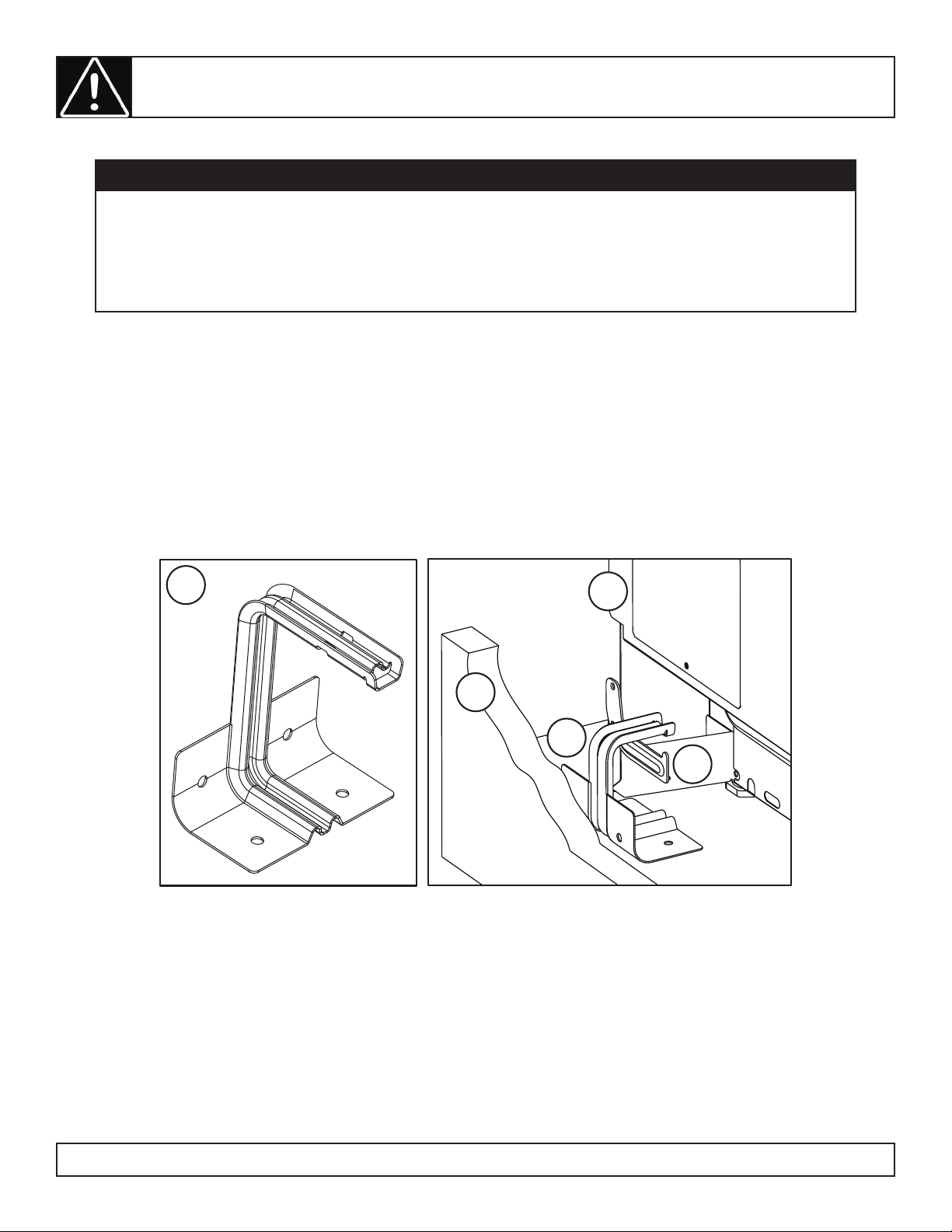
ANTI-TIP BRACKET INSTALLATION
1. Anti-tip arm on the back of the appliance
2. Anti-tip bracket
3. Screw must enter wood or concrete
4. Wall sill plate
5. Screw must enter wood
2
1
3
To reduce the risk of the appliance tipping, the antitip bracket must be installed before operation.
Note: The installation of the anti-tip bracket must
meet all local codes for securing the appliance.
The anti-tip bracket must be secured to either the
rear wall or the fl oor and must be positioned in such
a way that it will overhang the anti-tip arm on the
rear of the appliance.
4
5
Rear wall installation
Use the two screws provided to secure the bracket
to the rear wall. The screws must enter a wood sill
plate. If the wall contains any metal studs or similar
materials, or if the back of the appliance cannot
reach the rear wall, the fl oor installation should be
used.
Floor installation
Wood fl oor: Use the two screws provided to secure
the bracket to the fl oor.
Concrete fl oor:
1. Mark the location where the screws need to be
installed.
2. Use a power drill and a concrete bit to drill a
5/32” pilot hole 2” deep into the concrete at the
center of each of the marked locations.
3. Use the two screws provided to secure the
bracket to the fl oor.
Double check the installation
After installing the bracket, slide the appliance into
its fi nal location. Look underneath the appliance
and ensure that the anti-tip arm attached to the side
panel of the appliance is engaging the bracket.
7

INSTALLATION INSTRUCTIONS
POWER CORD AND STRAIN RELIEF INSTALLATION
Remove the wire cover on the lower back of the
range by removing its top center screw. Do not
discard this screw.
Remove the knockout ring located on the bracket
directly below the terminal block. To remove the
knockout, use a pair of pliers to bend the knockout
ring away from the bracket and twist until the ring is
removed.
For power cord installations
Assemble the strain relief in the hole of the bracket.
If tabs are present at the end of the winged strain
relief they can be removed for a better fi t.
Insert the power cord through the strain relief and
tighten. Allow enough slack to easily attach the cord
terminals to the terminal block.
Do not install the power cord without a strain relief.
The strain relief bracket should be installed before
reinstalling the rear range wiring cover.
1. Terminal block
2. Strain relief
3. Bracket
4. Power cord
1. Terminal block
2. Knockout ring in bracket
3. Knockout ring removed
1
3
2
For conduit installations
Purchase a squeeze connector matching the
diameter of your conduit and assemble it in the
hole of the bracket. Insert the conduit through the
squeeze connector and tighten. Allow enough slack
to easily attach the wires to the terminal block.
Do not install the conduit without a squeeze
connector. The squeeze connector should be
installed before reinstalling the rear range wiring
cover.
1. Terminal block
2. Squeeze connector
3. Bracket
4. Conduit
2
4
1
3
1
2
3
4
8

INSTALLATION INSTRUCTIONS
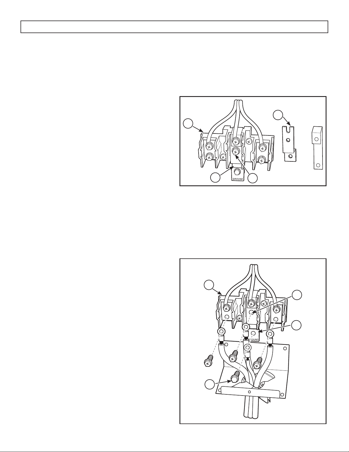
3 WIRE POWER CORD INSTALLATION
The neutral or ground wire of the power cord must
be connected to the neutral terminal located in the
center of the terminal block. The power leads must
be connected to the lower left and the lower right
terminals of the terminal block.
1. Remove the three lower terminal screws from the
terminal block.
2. Insert the three terminal screws through each
power cord terminal ring and into the lower
terminals of the terminal block.
3. Be certain that the center wire is connected to
the center lower position of the terminal block.
4. Tighten screws securely into the terminal block.
5. Do not remove the ground strap connection.
1. Terminal block
2. Neutral terminal
3. Ground strap
4. Power cord
5. Ground plate
1
2
5
3
4
9
INSTALLATION INSTRUCTIONS
4 WIRE POWER CORD INSTALLATION
The neutral wire of the supply circuit must be
connected to the neutral terminal located in the
lower center of the terminal block. The power
leads must be connected to the lower left and the
lower right terminals of the terminal block. The 4th
grounding lead must be connected to the frame of
the range with the ground plate and the ground
screw.
1. Remove the three lower terminal screws from the
terminal block.
2. Remove the ground screw and ground plate and
retain them.
3. Cut and discard the ground strap. Do not
discard any screws.
4. Insert the one ground screw into the power cord
ground wire terminal ring, through the ground
plate and into the frame of the range.
5. Insert the three terminal screws that were
removed earlier through each power cord
terminal right and into the lower terminals of the
terminal block.
6. Be certain that the center wire is connected to
the center lower position of the terminal block.
Before
1. Terminal block
2. Ground strap
3. Neutral terminal
4. Cut and discard the ground strap
2
1
4
After
1. Terminal block
2. Neutral terminal
3. Ground plate (grounding to range)
4. Ground screw
3
or
7. Tighten the screws securely into the terminal
block.
1
2
3
4
10
OPERATING INSTRUCTIONS
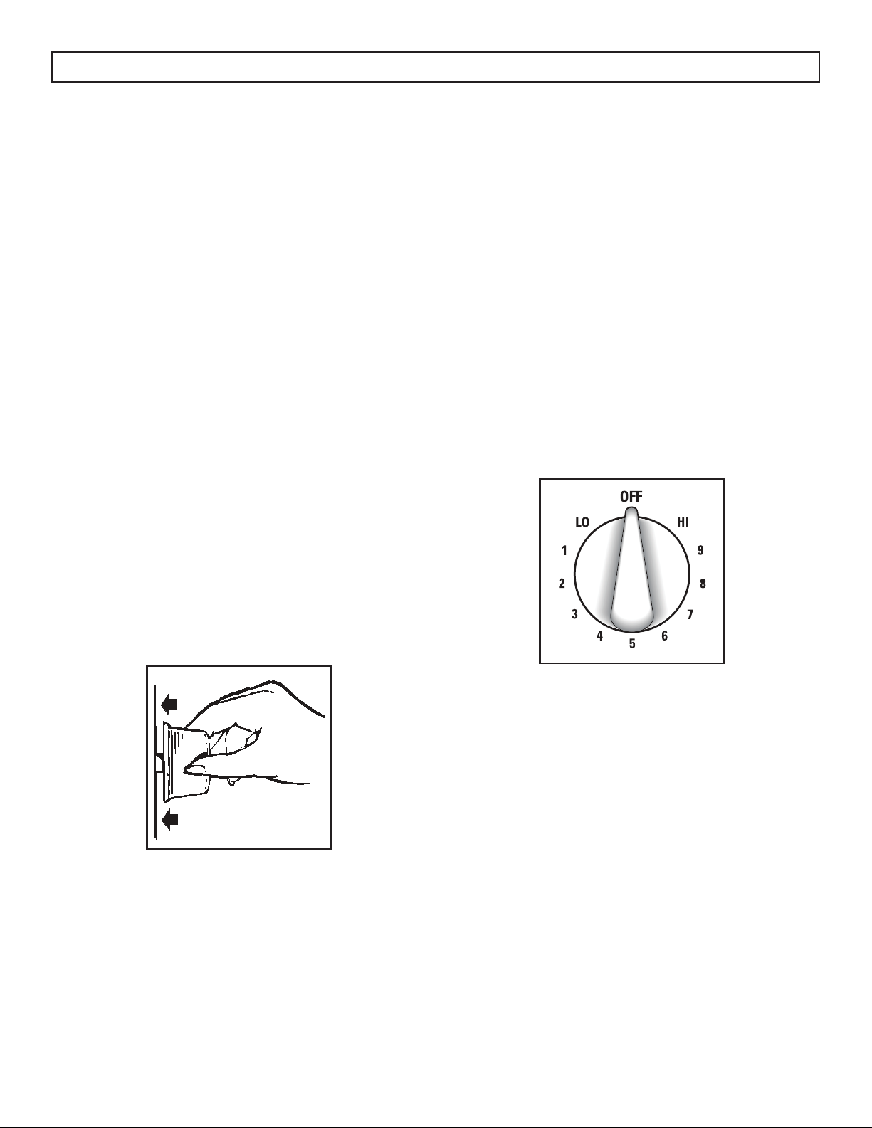
SURFACE COOKING CONTROLS
The surface heating elements of the appliance are
designed for a variety of heat settings.
At both the HI and LO positions, there are slight
indents and the knob will click into place in these
positions. HI indicates the highest setting. LO
indicates the lowest setting.
A sound of clicking may be heard from the
appliance during use. This is normal and indicates
that the heat setting selected is being maintained.
Changing to a higher heat setting will happen faster
than changing to a lower heat setting as it will take
time for the heat to dissipate.
SETTING THE CONTROLS
1. Push the control knob in.
2. Turn to the desired heat setting.
The knob only needs to be pushed in when moving
out of the “OFF” position. When the knob is in any
position other than “OFF”, it can be turned without
pushing in.
HEAT SETTING GUIDE
• HI - quick start for cooking; bringing water to a
boil
• MEDIUM HIGH - Fast fry; pan broil; maintain a
fast boil on a large amount of food
• MED - Sauté and brown; maintain a slow boil
on a large amount of food
• MEDIUM LOW - Cereal; maintain the serving
temperature of most foods
• LO - Cook after starting at HI; cook with little
water in a covered pan; use to steam rice; melt
chocolate or butter
Never leave food unattended while cooking. Boil
overs cause smoking. Greasy spill overs may catch
fi re.
Ensure that the element is turned off when cooking
is fi nished. An indicator light will glow when any
heating element is turned on.
SURFACE COOKING TIPS
Use medium or heavyweight cookware. Aluminum
cookware conducts heat faster than other metals.
Cast-iron and coated cast-iron cookware is slow to
absorb heat, but generally cooks evenly at low or
medium heat settings. Steel pans may cook unevenly
if not combined with other metals.
Do not overfi ll cookware with fat that may spill over
when adding food. Frosty foods bubble vigorously.
Watch foods frying at high temperatures. Keep
range and hood clean from accumulated grease.
To conserve the most cooking energy, pans should
be fl at on the bottom, have straight sides and tightfi tting lids. Match the size of the saucepan to the
size of the surface element. A pan that extends more
than an inch beyond the edge of the drip pan traps
heat, which causes “crazing” (fi ne hairline cracks)
on porcelain, and discoloration ranging from blue
to dark gray on chrome drip pans.
11
 Loading...