


DAC8011E

Danby Products Limited, Ontario, Canada N1H 6Z9
Danby Products Inc., Findlay, Ohio, USA 45840
Model • Modèle • Modelo
• Owner’s Use and Care Guide
• Guide d’utilisation et soins de Propriètaire
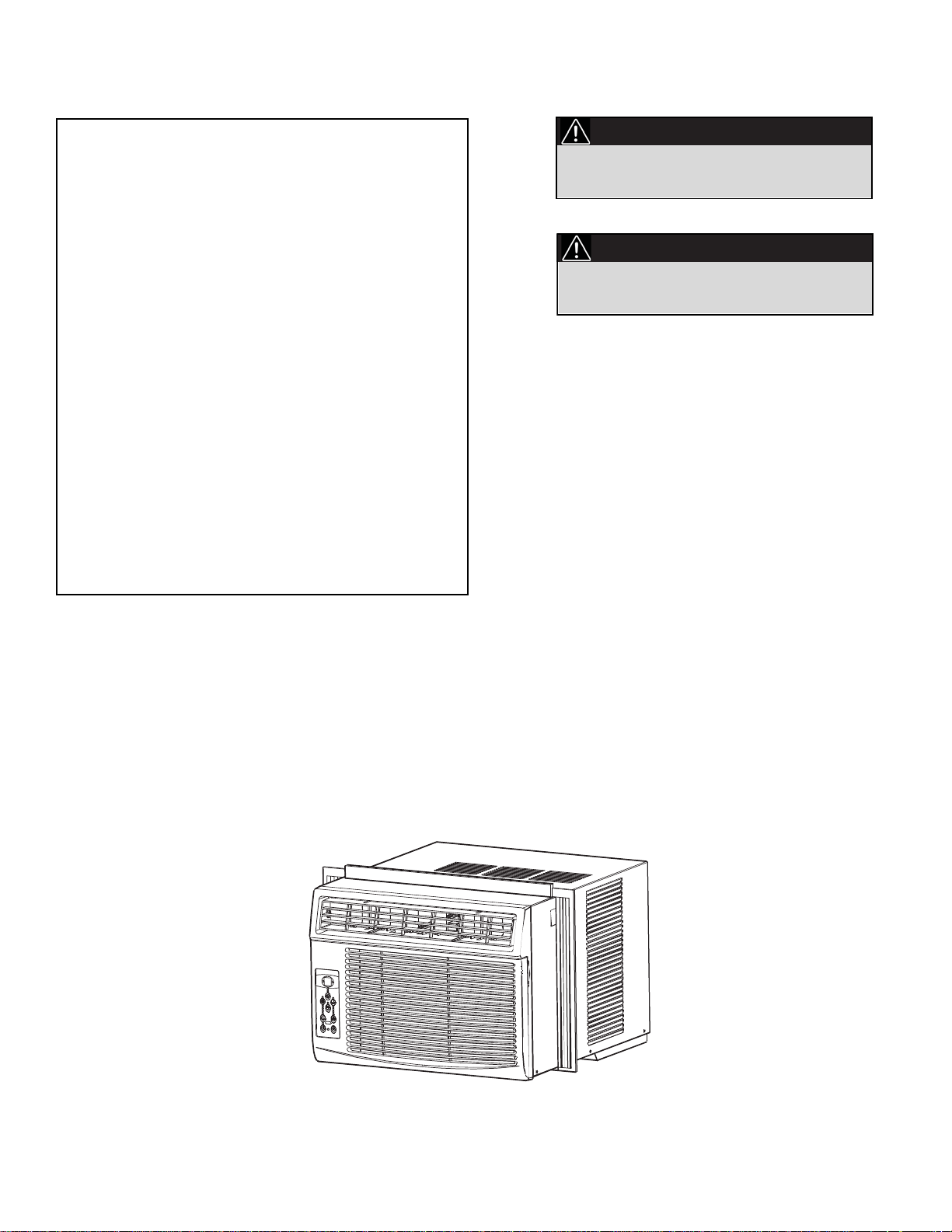
AIR CONDITIONER
CLIMATISEUR
V1 11.10 DM
DAC8010E / DAC8011E
Contents
CAUTION:
PRECAUTION:
Read and follow all safety rules and operating instructions before first use of this product.
Veuillez lire attentivement les consignes de
sécurité et les instructions d’utilisation avant
l’utilisation initiale de ce produit.
CLIMATISEUR
Guide d'utilisation et d'entretien ........................
• Bienvenue
• Consignes de Sécurité Importantes
• Caractéristiques
• Installation
• Consignes d’utilisation
• Soins et Entretien
• Dépannage
• Garantie
2-17
AIR CONDITIONER
Owner’s Use and Care Guide .............................
• Welcome
• Important Safety Information
• Features
• Installation
• Operation Instructions
• Care and Maintenance
• Troubleshooting
• Warranty
Model • Modèle DAC8010E / DAC8011E
18-33
Welcome
Thank you for choosing a Danby appliance to provide you and your family with all of the “Home Comfort” requirements
of your home, cottage, or office. This Owner’s Use and Care Guide will provide you with valuable information necessary
for the proper care and maintenance of your new appliance. If properly maintained, your Danby appliance will give you
many years of trouble free operation. Please take a few moments to read the instructions thoroughly and familiarize
yourself with all of the operational aspects of this appliance.
For easy reference, may we suggest you attach a copy of your sales slip/receipt to this page, along with the following
information, located on the manufacturers nameplate on the side of the unit.
NOTE: THIS UNIT IS NOT DESIGNED FOR “THROUGH-THE-WALL” INSTALLATION.
Model Number:
Serial Number:
Date of Purchase:
This information will be necessary if your unit requires servicing and/or for general inquiries. To contact a Customer
Service Representative, call Danby TOLL FREE: 1-800-263-2629
2
WARNING
Improper connection of the grounding plug can result in risk of
Fire, Electric Shock and/or injury to Persons associated with the
appliance. Check with a qualified service representative if in doubt
that the appliance is proplery grounded.
Important Safety Information
READ AND FOLLOW ALL SAFETY INSTRUCTIONS
ELECTRICAL
SPECIFICATIONS
FOR YOUR SAFETY: Read these instructions carefully before operating the unit.
1) All wiring must comply with local and national electrical codes and must
be installed by a qualified electrician. If you have any questions
regarding the following instructions, contact a qualified electrician.
2) Check available power supply and resolve any wiring problems
BEFORE installing and operating this unit.
3) This 115V air conditioner uses 7 or less nameplate amps and may be
used in any properly wired, general purpose household receptacle. See
Table 1 for specifications for individual branch circuit.
4) For your safety and protection, this unit is grounded through the power
cord plug when plugged into a matching wall outlet. If you are not sure
whether your wall outlet is properly grounded, please consult a qualified
electrician.
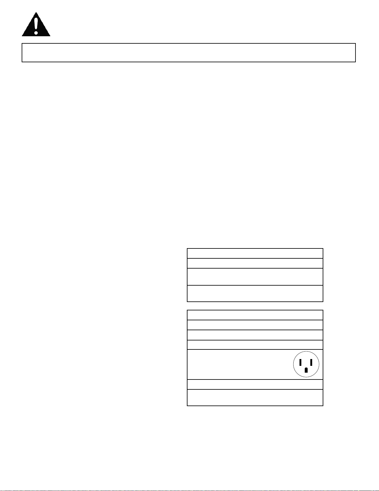
5) The wall outlet must match the 3-prong plug on the service cord
supplied with the unit. DO NOT use plug adapters. See Table 2 for
receptacle and fuse information. If it is necessary to use an extension
cord to connect your air conditioner, use an approved “air
conditioner” extension cord only (available at most local hardware
stores).
6) The rating plate on the unit contains electrical and other technical data.
The rating plate is located on the right side of the unit, above the power
cord.
3
TABLE 1
Suggested Individual Branch Circuit
Nameplate Amps *AWG Wire Size
716
AWG- American Wire Gauge
*Based on copper wire at 60°C temperature rating.
TABLE 2
Receptacle and Fuse Types
Rated Volts 125
Amps 15
Wall Outlet
Fuse Size 15
Time Delay Fuse Plug Type
(or Circuit Breaker)
Important Safety Information
READ AND FOLLOW ALL SAFETY INSTRUCTIONS
ENERGY SAVING TIPS
FOR YOUR SAFETY: Read these instructions carefully before operating the unit.
Your Danby appliance is designed to be highly efficient in energy
savings. Follow these recommendations for greater efficiency.
1) Select a thermostat setting that suits your comfort needs and leave at
that chosen setting.
2) The air filter is very efficient in removing airborne particles. Keep the air
filter clean at all times. (usually cleaned every 2 weeks depending on
indoor air quality).
3) Use drapes, curtains or shades to keep direct sunlight from penetrating
and heating the room, but do not allow drapes or curtains to obstruct
the air flow around the unit.
4) Start your air conditioner before the outdoor air becomes hot and
uncomfortable, to avoid an initial period of discomfort while the unit is
cooling off the room.
5) When outdoor temperatures are cool enough, use HIGH or LOW FAN
only. This circulates indoor air, providing some cooling comfort, and
utilizes less electricity than when operating on a cooling setting.
4
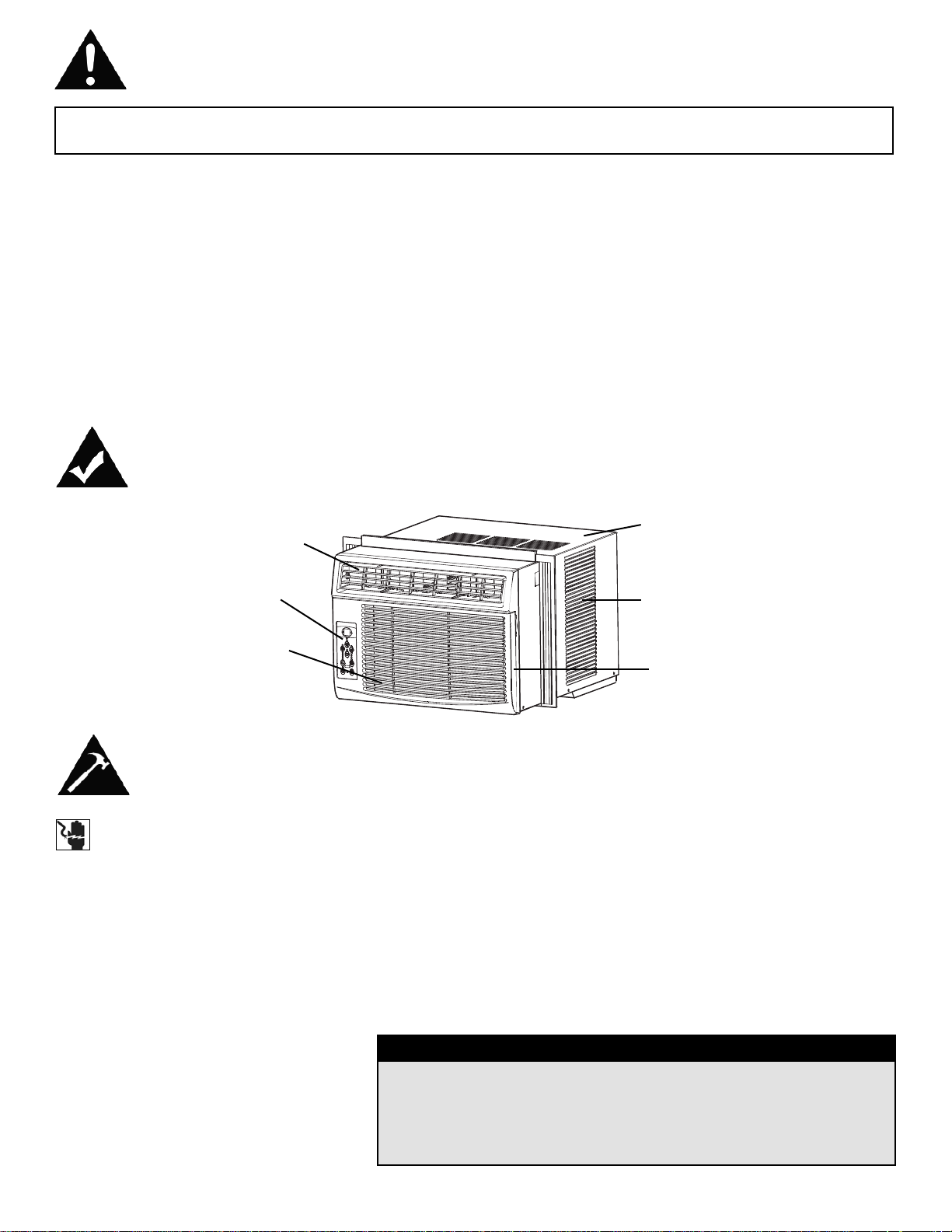
Features
Air FIlter
Exterior
Air Inlet
Cabinet
Interior Air Inlet
Control Panel
Interior Air Outlet
Installation Instructions
CAUTION
Because the compressor is located on the controls side of the unit
(left side), this side will be heavier and more awkward to manipulate. Inadequate support on control side of the unit can result in
personal injury and damage to your unit and property. Therefore, it
is recommended that you have someone assist you during the
installation of this unit.
TOOLS NEEDED FOR INSTALLATION:
• Screw Drivers: Phillips and flat head.
• Power Drill: 1/8” (3.2mm) diameter drill bit.
• Pencil
• Measuring Tape
• Scissors
• Carpenters Level
NOTE: Save the shipping carton and packing materials for future storage
or transportation. From carton, remove the plastic bag containing the
installation hardware kit necessary for the installation of your air
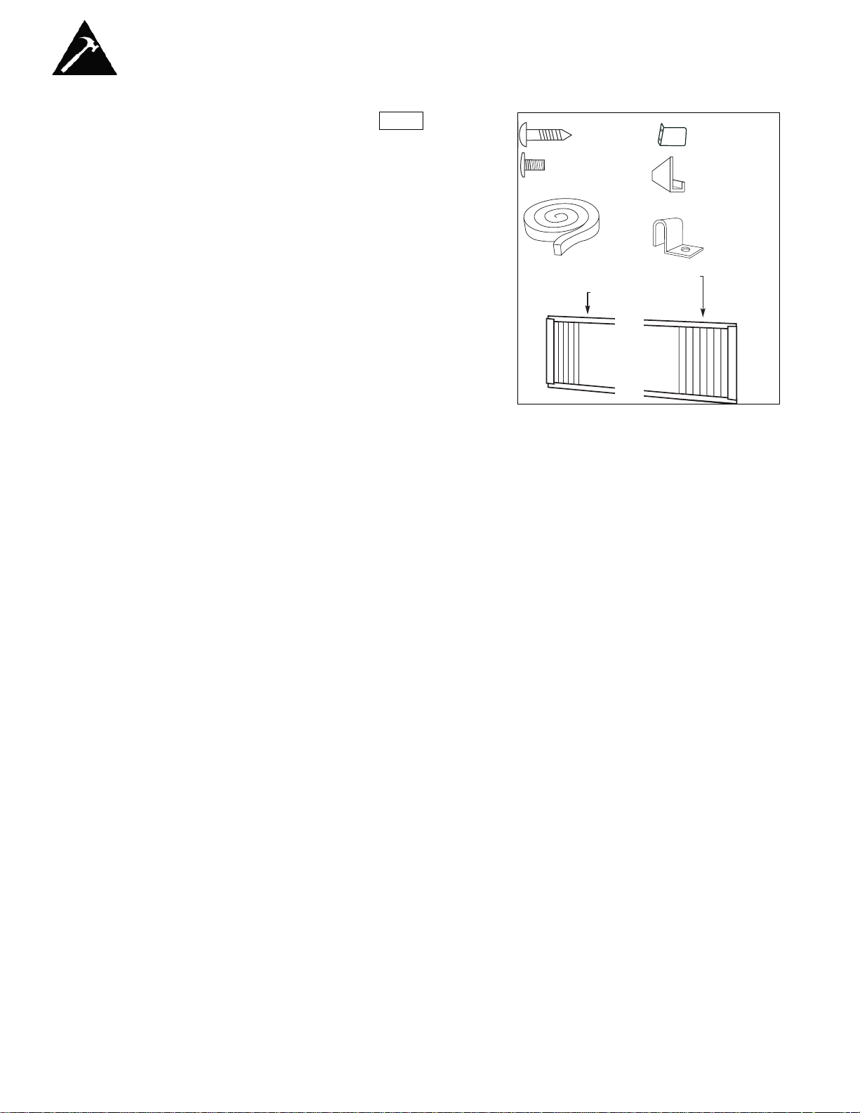
conditioner. Please check the contents of hardware kit against the corresponding model check list, prior to installation of the unit. See Fig. 1.
ELECTRIC SHOCK HAZARD
To avoid the possibility of personal
injury, disconnect power to the unit
before installing or servicing.
NOTE: Your Room Air Conditioner is
designed for easy installtion in a single or
double-hung window. This unit is NOT
designed for vertical (slider type) windows
and/or through-the-wall applications.
Installation Instructions
Fig. 1
INSTALLATION
HARDWARE
LOCATION
A) This room air conditioner is designed to fit easily into a single or double
hung window. However, since window designs vary, it may be
necessary to make some modifications for safe, proper installation.
B) Make sure window and frame are structurally sound and free from dry
and rotted wood.
C) For maximum efficiency, install the air conditioner on a side of the
house or building which favours more shade than sunlight. If the unit is
in direct sunlight, it is advisable to provide an awning over the unit.
D) Provide sufficient clearance around the cabinet to allow for ample air
circulation through the unit (See Fig. 2). The rear of the unit should be
outdoors and not in a garage nor inside a building. Keep unit as far
away as possible from obstacles/obstructions and at least 30” above
the floor or ground. Curtains and other objects within a room should be
prevented from blocking the air flow.
E) Be certain the proper electrical outlet is within reach of the installation.
Use only a single outlet circuit rated at 15 amps. All wiring should be in
accordance with local and national electrical codes.
F) DO NOT install unit where leakage of combustible gas is suspected.
Your air conditioner may fail to operate in air containing oils (including
machine oils), sulfide gas, near hot springs, etc.
NOTE: Your unit is designed to evaporate condensation under normal
conditions. However, under extreme humidity conditions, excess condensation may cause basepan to overflow to the outside. The unit should be
installed where condensation run-off cannot drip on pedestrains or neighboring properties.
5
3/4in. (19.1mm)
screws (7)
Safety Lock (1)
3/8in. (9.5mm) screws
(4) *Factory installed
on some models
“L” Shaped
mounting
bracket (1)
* Factory installed
on some models
Sash bracket (2)
Adhesive
Foam Seal(1)
Side Curtain LH (1)
Side Curtain RH (1)
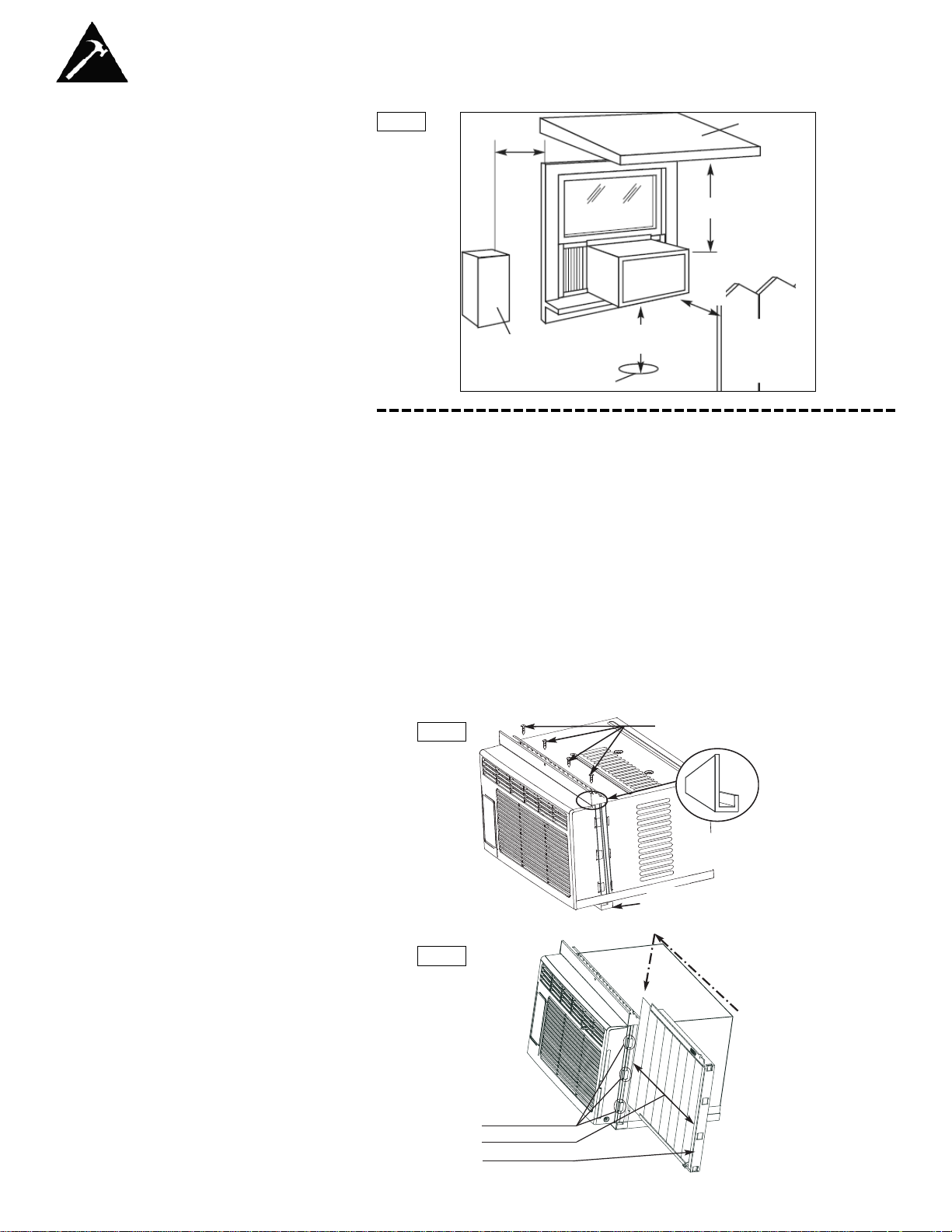
LOCATION
Installation Instructions
Awning
Fence,
wall, or
other
obstacle
Ground
Side
Obstruction
20”
Min
30”
Min
20”
Min
12” Min
Fig. 2
1) Assembly of the Upper Channel to Cabinet.
(Factory installed on some units)
• “L” Shaped Top Channel: Install the “L” shaped channel to the top of the
cabinet as shown in Fig. 3, using four (4) 3/8” screws.
2) Assembly of the Side Curtains to Cabinet.
• Extend the shutter from the shutter frame and slide it into the shutter tabs
on the side channel of the air conditioner, as shown in Fig. 4.
• Slide the shutters into the top (“L” Shaped) and bottom (“U” Shaped)
channels. The shutters are identified (on frame) as left and right.
3) Completing the Installation
• Cut the foam (non adhesive) sealing strip to fit the area of the window sill
that the air conditioner will rest on.
3/8” screws
“L” shaped mounting
bracket
“U” shaped Channel
(Factory Installed)
Slide down into tabs
Shutter tabs
Shutter
Shutter frame
Fig. 3
Fig. 4
6
7
Installation Instructions
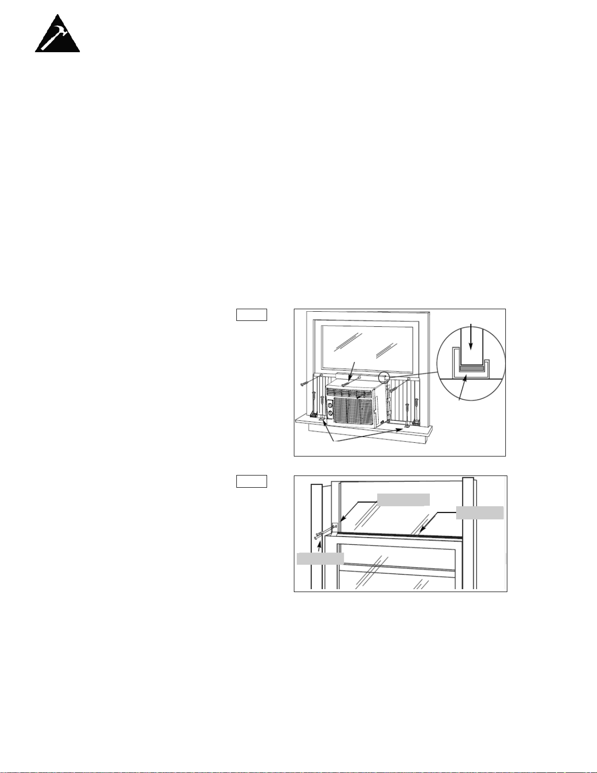
3) Completing the Installation (cont)
• Carefully place the air conditioner into the window with the “L” shaped
mounting bracket (on top) positioned in front of the upper window sash.
The bottom of the cabinet should be positioned on the “recessed” portion
of the window frame. Pull the window down until it rests just behind the
front flange of the (top) “L” shaped mounting bracket (See Fig. 5).
• Expand the shutter frames (fully) on each side and secure the top of the
frames to the window sash using one 3/4” screw on each side and one in
the “L” shaped mounting bracket (Fig. 5).
• Secure the shutter clamp on each side of the (lower) shutter and secure
to window sill using one 3/4” screw on each side (Fig. 5).
• Place the second foam sealing strip to fit the opening between the inside
and outside windows, then attach the safety lock to the outside window
frame using one 3/4” screw (See Fig. 6).
PLEASE NOTE: Window applications come in a variety of different styles.
Therefore, it may be necessary to modify or improvise your particular
installation.
Window sash
“L” Shaped
Mounting
Bracket
Shutter clamps
3/4” screws
Fig. 5
Safety Lock
3/4” screw
Foam Seal
Fig. 6
Operating Instructions
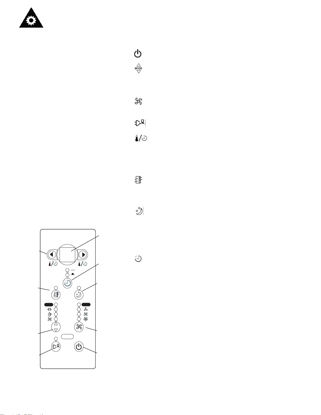
KEY PAD FEATURES
8
LED DISPLAY: Displays the following information independently;Set
Temperature, Ambient RoomTemperature and Auto Timer On/Off settings.
POWER: Turns unit On/Off.
MODE: Allows you to scroll through and select the desired operating
mode; Cool , Dry , Fan Only and *Auto .The selected mode will be denoted by the adjacent indicator light.*‘Auto’is a pre-set factory program that
automatically defines the mode (Cool or Dry) and fan speed based on the
set temperature.
FAN SPEED: Select from four different fan settings;Low , Medium ,
High and Auto during Cool and Fan Only mode. Please note: During ‘Dry’
mode the fan speed is automatically defined .
ENERGY SAVER: Automatically cycles the fan on and off while the
compressor is not in use.
TEMP / TIMER CONTROL: Used to increase or decrease
the Temperature setting in 1°C / °F increments, and Auto-Timer On/Off settings in 30min./1hr. increments. Note: This appliance allows you select the
temperature scale to be displayed in either “Celsius” or Fahrenheit”
according to your preference.To change the temperature scale displayed
on the electronic display, press both the “Temp/Timer”adjust arrows simultaneously to alternate between “Celsius” & “Fahrenheit”.
CHECK FILTER: The adjacent indicator light will illuminate as a
reminder to clean the air conditioner filter (see page 9) Once the filter has
been cleaned and replaced, depress the Check Filter button in order to
resume operation.
SLEEP MODE: When activated, the current set temperature is gradu-
ally increased over a one (1) hour period then maintained for seven (7)
hours. Once the program is complete, the air conditioner will resume to its
previous set temperature (before sleep mode was activated). This feature
is mean to be used during the night time hours to prevent the room from
getting too cold (while you sleep) and results in less compressor running
time and reduced energy consumption. Sleep mode may be cancelled by
depressing the Sleep Mode button while the program is running.
AUTO-TIMER: Used to initiate the Auto On/ Auto Off timer.
While the Air Conditioner is off (Auto-On):
1) Press the Auto-Timer button once and the adjacent Auto-On indicator
light will illuminate.
2) Use the Temp/Timer control cursors to select a delayed On time of
up to 24 hours.
3) Select the appropriate mode under which you want the unit to operate
(Auto-Cool-Dry-Fan Only)
4) Select the fan speed setting.
5) The time you selected will appear in the LED display.
While the Air Conditioner is on (Auto-Off):
1) Press the Auto-Timer button twice and the adjacent Auto-Off indicator
light will illuminate.
2) Use the Temp/Timer control cursors to select a delayed Off time of up
to 24 hours.
3) The time you selected will appear in the LED display. The Auto On and
Auto Off timer can operate during the same program by defining the
Auto-Off parameters immediately after the Auto On parameters.The
Auto-Timer may be cancelled at any time by turning the unit On/Off.
MODE
Auto
Auto
68
Temp / Timer
Control
Check
Filter
Mode
Selector
Energy
Saver
LED
Display
Auto
Timer
Sleep
Mode
Fan
Speed
Power
Button
Operating Instructions
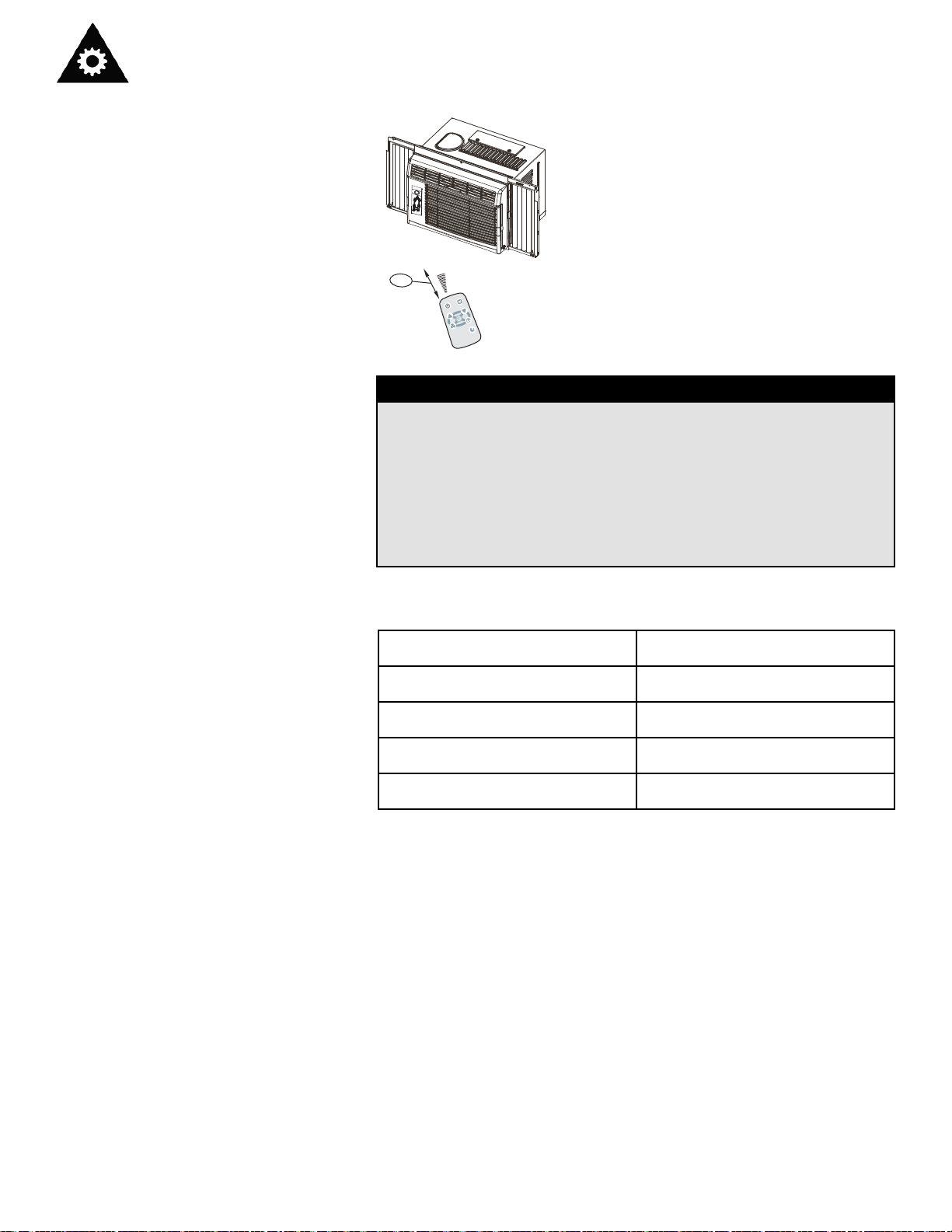
USING THE REMOTE
CONTROL
Location of the remote controller.
• Use the remote controller within a distance of 5
meters from the appliance, pointing it towards
the receiver. Reception is confirmed by a beep.
CAUTION
• The air conditioner will not operate if curtains, doors or other
materials block the signals from the remote controller to the
indoor unit.
• Prevent any liquid from falling into the remote controller. Do not
expose the remote controller to direct sunlight or heat.
• If the infrared signal receiver on the indoor unit is exposed to
direct sunlight, the air conditioner may not function properly. Use
curtains to prevent the sunlight from falling on the receiver.
• If other electrical appliances react to the remote controller, either
move these appliances or call the service depot.
REMOTE CONTROLLER
SPECIFICATIONS
Model
Rated Voltage
Lowest Voltage of
CPU Emitting Signal
Signal Receiving Range
Environment
R15A, R15B, R15C
3.0V(Button cell: CR2025)
2.0V
5m
-5°C ~ 60°C
9
5m
E
D
O
M
F
F
O
/
N
O
P
M
E
N
T
W
O
D
P
M
TE
P
U
G
N
I
W
S
R
E
M
I
T
N
A
F
EEP
L
S
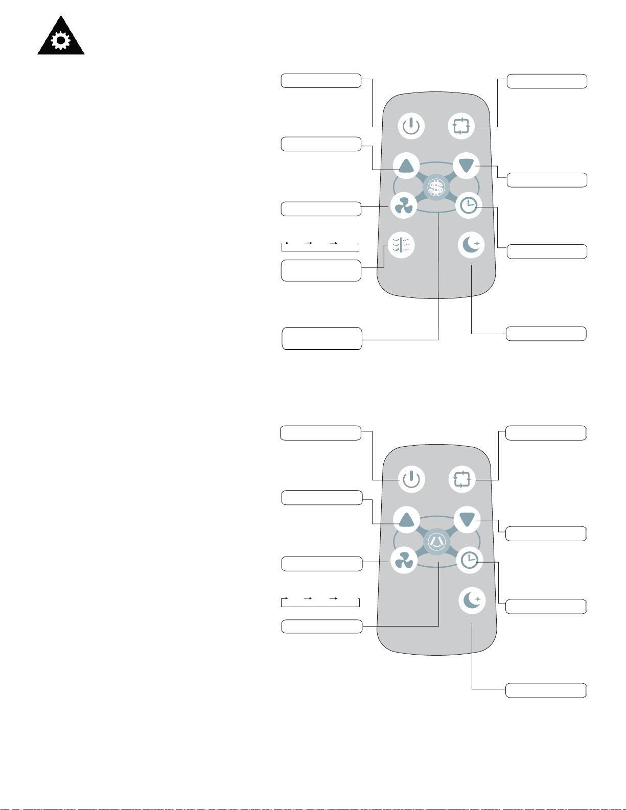
Operating Instructions
ON/OFF button
TEMP UP button
FAN button
CLEAN AIR button
(on some models)
ENERGY SAVER
button
MODE button
TEMP DOWN button
TIMER button
SLEEP button
Operation starts when
this button is pressed
and stops when the
button is pressed again.
Push this button to
increase the temperature setting in 1°C
increments to 30°C.
Used to select the fan
speed in three steps:
LOW
MED
HIGH
When this button is
pressed, the ion generator is energized and will
help remove pollen and
impurities from the air.
Press this button to
activate the Energy saving mode. Press it again
to stop the funtion.
Each time you press
this button, a mode is
selected in a sequence
that goes from AUTO,
HEAT (cooling and heating models only) COOL,
DRY, FAN and back to
AUTO.
Push this button to
decrease the indoor
temperature setting in
1°C increments to 17°C.
Push this button to
activate the “Auto
Start” or “Auto Stop”
program from 0-12
hours (1 hour increments)
Press this button to
activate the Sleep
mode. This function is
available on COOL,
HEAT or AUTO mode
only and maintain the
most comfortable
temperature for you.
REMOTE
CONTROLLER
BUTTONS
ON/OFF button
TEMP UP button
FAN button
SWING button
MODE button
TEMP DOWN button
TIMER button
SLEEP button
Operation starts when
this button is pressed
and stops when the
button is pressed again.
Push this button to
increase the temperature setting in 1°C
increments to 30°C.
Used to select the fan
speed in three steps:
LOW
MED
HIGH
When this button is
pressed, the vertical louvres will swing automatically from side to side.
Press it again to deactivate the "SWING" feature.
Each time you press
the button, a mode is
selected in a sequence
that goes from AUTO,
HEAT (cooling and heating models only) COOL,
DRY, FAN and back to
AUTO.
Push this button to
decrease the indoor
temperature setting in
1°C increments to 17°C.
Push this button to
activate the “Auto
Start” or “Auto Stop”
program from 0-12
hours (1 hour increments)
Press this button to
activate the Sleep
mode. Press again to
stop the function. This
function is available on
COOL, HEAT or AUTO
mode only and maintain
the most comfortable
temperature for you.
Models:
R15A
R15B
Models:
R15C
NOTE: Modle R15B does not have
CLEAN AIR feature.
10
ON/OFF
TEMP
UP
FAN
CLEAN
AIR
S
ENERGY
SAVER
MODE
TEMP
DOWN
TIMER
SLEEP
ON/OFF
TEMP
UP
FAN
SWING
MODE
TEMP
DOWN
TIMER
SLEEP
 Loading...