


OWNER’S USE AND CARE GUIDE
GUIDE D’UTILISATION ET SOINS DE PROPRIÈTAIRE
AIR CONDITIONER
CLIMATISEUR
MODEL MODÈLE
Model Modèle Modelo
DAC080EB2GDB / DAC100EB2GDB
DAC120EB2GDB
DANBY PRODUCTS LIMITED, ONTARIO, CANADA N1H 6Z9
DANBY PRODUCTS INC., FINDLAY, OHIO, USA 45840
03.01.14

TO OBTAIN WARRANTY SERVICE YOU MUST PROVIDE A VALID PROOF OF
PURCHASE. PLEASE STAPLE YOUR RECEIPT TO THIS PAGE FOR FUTURE
REFERENCE.
------------------------------------------------------------------------------------------------------------------POUR OBTENIR LE SERVICE SUR GARANTIE VOUS DEVEZ FOURNIR UNE
PREUVE D’ACHAT VALIDE. VEUILLEZ AGRAFER VOTRE REÇU À CETTE PAGE
POUR RÉFÉRENCE FUTURE.
-------------------------------------------------------------------------------------------------------------------
IMPORTANT - GROUNDING METHOD
This product is factory equipped with a power supply cord that has a three-pronged grounded plug. It must
be plugged into a mating grounding type receptacle in accordance with the National Electrical Code and
applicable local codes and ordinances. If the circuit does not have a grounding type receptacle, it is the
responsibility and obligation of the customer to exchange the existing receptacle in accordance with the
National Electrical Code and applicable local codes and ordinances. The third ground prong should not,
under any circumstances, be cut or removed.
IMPORTANT - MÉTHODE POUR LA MISE À LA TERRE
Ce produit arrive d’origine avec un cordon d’alimentation équipé d’une prise à trois fi ches. Il doit être
branché dans une prise avec une fi che de mise à la terre en conformité avec le Code National de l’Électricité
et les codes et règles locales applicables. Si le prise murale n’a pas de mise à la de terre, il est de la
responsabilité et l’obligation du client de changer la prise existante pour la rendre conforme aux Codes
Nationaux de l’Électricité, aux codes et règles locaux applicables. La fi che de la mise à la terre ne doit pas,
en aucune circonstance, être coupée ou retirée.
CONTENTS
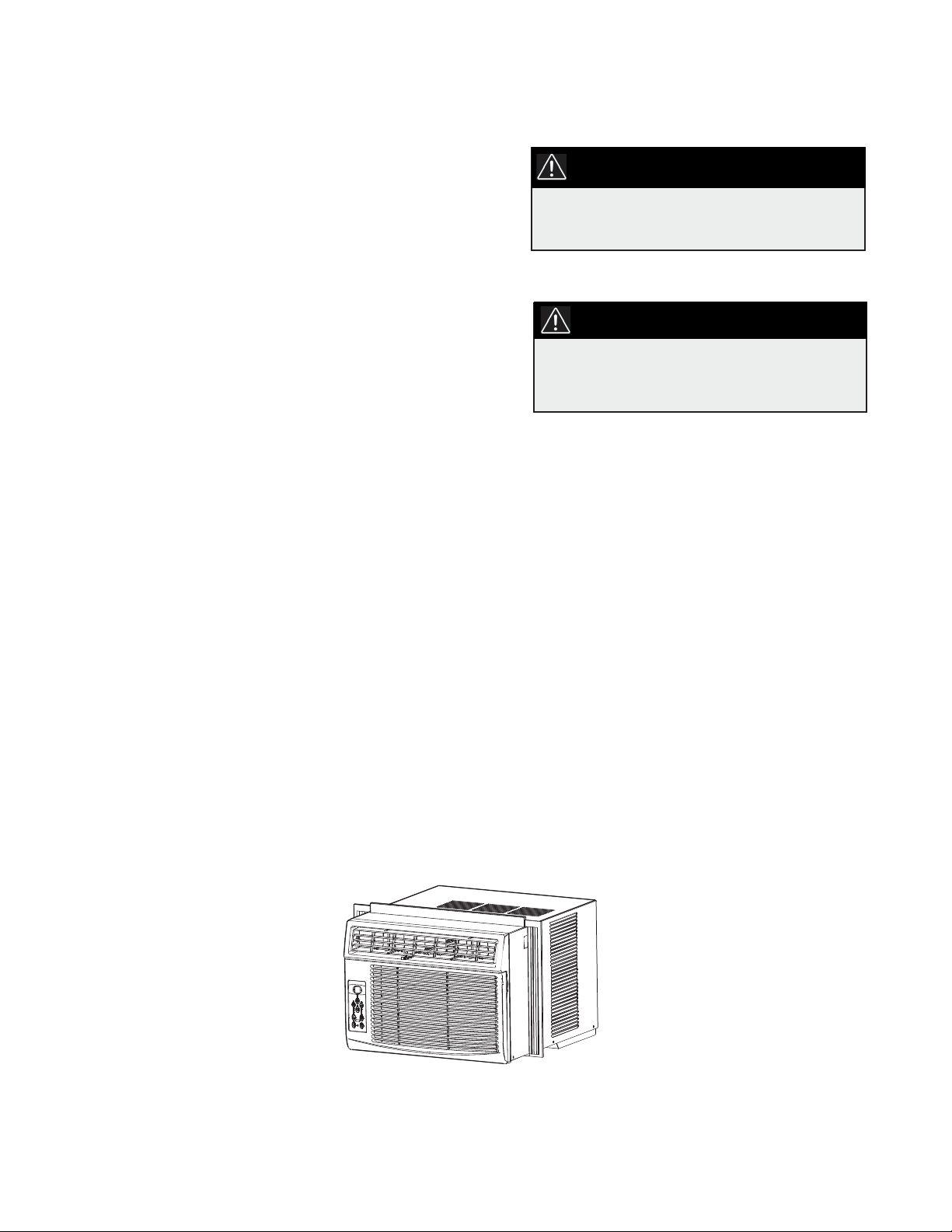
AIR CONDITIONER
Owner’s Use and Care Guide ................................1-16
• Welcome
• Important Safety Information
• Features
• Installation Instructions
• Operation Instructions
• Care and Maintenance
• Troubleshooting
• Warranty
CLIMATISEUR
Guide d’utilisation et d’entretien du propriétaire...17-32
• Bienvenue
• Consignes de sécurité importantes
• Caractéristiques
• Consignes d’installation
• Consignes d’utilisation
• Soins et entretien
• Dépannage
• Garantie
CAUTION:
Read and follow all safety rules and operating
instructions before ¿ rst use of this product.
PRÉCAUTION:
Veuillez lire attentivement les consignes de
sécurité et les instructions d’utilisation avant
l’utilisation initiale de ce produit.
Model • Modèle DAC080EB2GDB / DAC100EB2GDB
DAC120EB2GDB
WELCOME
Welcome to the Danby family. We are proud of our quality products, and we believe in dependable service, like you will
fi nd in this Owner’s Use and Care Guide, and like you will receive from our friendly customer service department. Best of
all, you will experience these values each and every time you use your Danby appliance. That is important, because your
new appliance will be a part of your family for a long time.
For easy reference, we suggest you attach a copy of your sales slip/receipt to this page, along with the following
information, located on the manufacturer’s nameplate on the right side of the unit above the powercord.
Note the information below; you will need this information to obtain service under warranty.
To receive service, you must provide the original receipt.
NOTE: THIS UNIT IS NOT DESIGNED FOR “THROUGH-THE-WALL” INSTALLATION
Model No:
Serial No:
Date Purchased:
NEED HELP?
Before you call for service, here are a few things you can do to
help us serve you better:
Read this Owner’s Use and Care Guide:
It contains instructions to help you use and maintain your
appliance properly.
If you received a damaged appliance:
Immediately contact the retailer (or builder) that sold you the
appliance.
Save time and money:
Check the Troubleshooting section at the end of the guide
before calling. This section helps you solve common problems
that may occur.
If you do need service, you can relax, knowing help is only a
phone call away.
Tel: 1-800-26-
(1-800-263-2629)
WARNING
Improper connection of the grounding plug can result in risk of
fi re, electric shock and/or injury to persons associated with the
appliance. Check with a qualifi ed service representative if in doubt
that the appliance is properly grounded.
1
Important Safety Information
READ AND FOLLOW ALL SAFETY INSTRUCTIONS
FOR YOUR SAFETY: Read these instructions carefully before operating the unit.
ELECTRICAL
SPECIFICATIONS
1) All wiring must comply with local and national electrical codes and must
be installed by a qualified electrician. If you have any questions
regarding the following instructions, contact a qualified electrician.
2) Check available power supply and resolve any wiring problems
BEFORE installing and operating this unit.
3) This 115V air conditioner uses 9.5 or less nameplate amps and may
be used in any properly wired, general purpose household receptacle.
See Table 1 for the specifications for the individual branch circuit.
4) For your safety and protection, this unit is grounded through the power
cord plug when plugged into a matching wall outlet. If you are not sure
whether your wall outlet is properly grounded, please consult a qualified
electrician.
5) The wall outlet must match the 3-prong plug on the service cord
supplied with the unit. DO NOT use plug adapters. See Table 2 for
receptacle and fuse information. If it is necessary to use an extension
cord to connect your air conditioner, use an approved “air
conditioner” extension cord only (available at most local hardware
stores).
6) The rating plate on the unit contains electrical and other technical data.
The rating plate is located on the right side of the unit, above the power
cord.
TABLE 1 DAC080EB2GDB
Suggested Individual Branch Circuit
Nameplate Amps *AWG Wire Size
616.2
AWG- American Wire Gauge
*Based on copper wire at 60°C temperature rating.
TABLE 1 DAC100EB2GDB
DAC120EB2GDB
Suggested Individual Branch Circuit
Nameplate Amps *AWG Wire Size
41 o 9.5t 7.7
AWG- American Wire Gauge
*Based on copper wire at 60°C temperature rating.
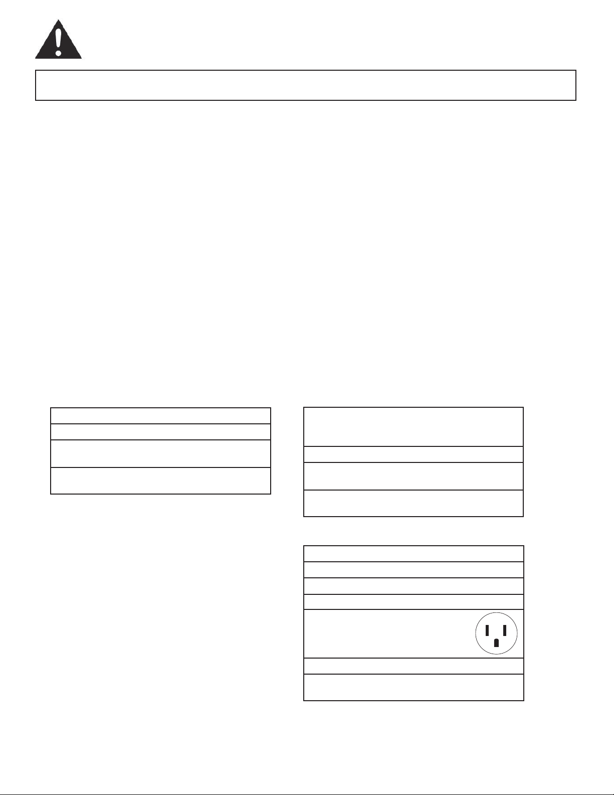
TABLE 2
Receptacle and Fuse Types
521stloV detaR
51spmA
Wall Outlet
51eziS esuF
epyT gulPesuF yaleD emiT
(or Circuit Breaker)
2
Important Safety Information
READ AND FOLLOW ALL SAFETY INSTRUCTIONS
FOR YOUR SAFETY: Read these instructions carefully before operating the unit.
ENERGY SAVING TIPS
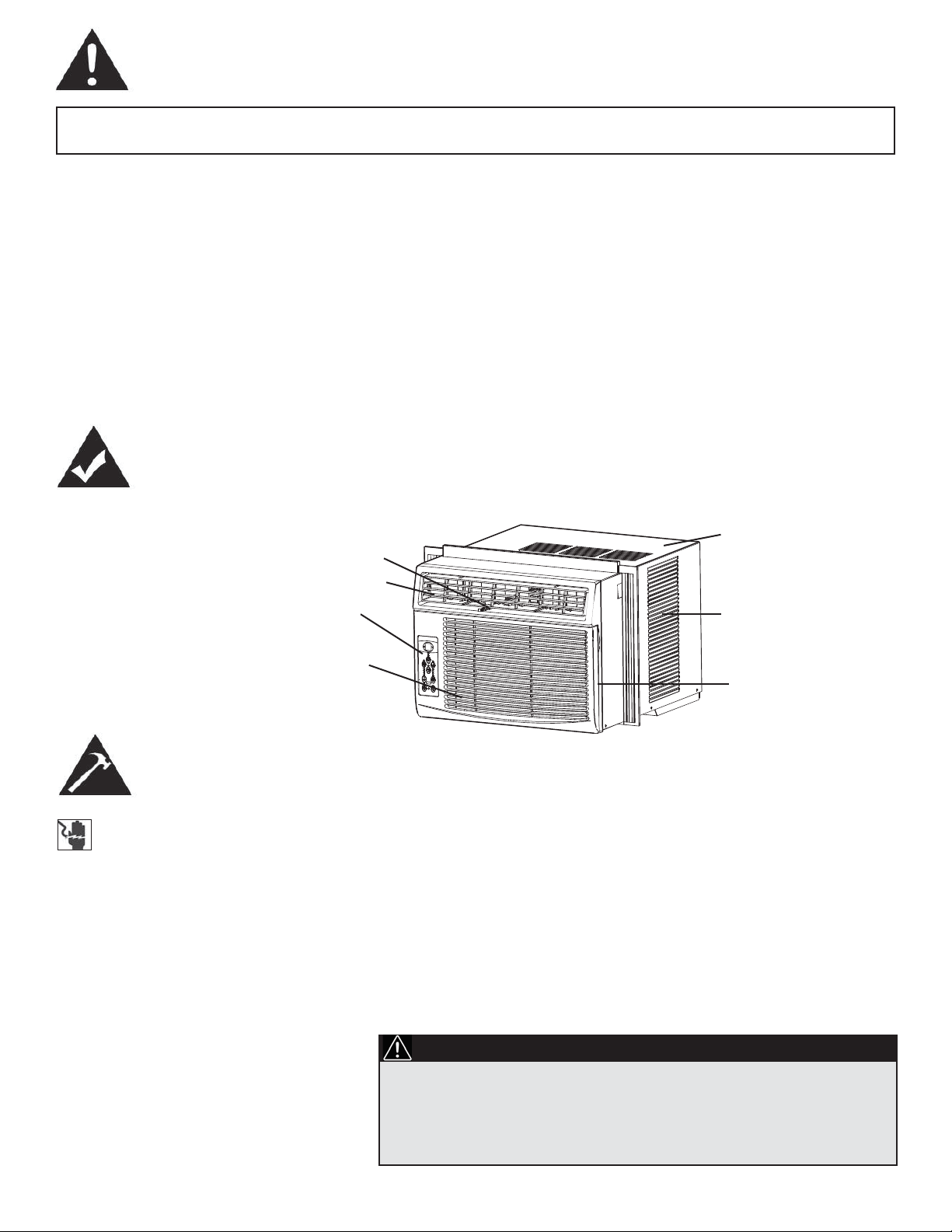
Features
Fresh Air Ventilation Switch
(open for Fan only operation,
available in DAC100EB2GDB
and DAC120EB2GDB only)
Interior Air Outlet
Control Panel
Your Danby appliance is designed to be highly efficient in energy
savings. Follow these recommendations for greater efficiency.
1) Select a thermostat setting that suits your comfort needs and leave at
that chosen setting.
2) The air filter is very efficient in removing airborne particles. Keep the air
filter clean at all times. (usually cleaned every 2 weeks depending on
indoor air quality).
3) Use drapes, curtains or shades to keep direct sunlight from penetrating
and heating the room, but do not allow drapes or curtains to obstruct
the air flow around the unit.
4) Start your air conditioner before the outdoor air becomes hot and
uncomfortable, to avoid an initial period of discomfort while the unit is
cooling off the room.
5) When outdoor temperatures are cool enough, use the FAN MODE only,
on HIGH, MED., or LOW setting. This circulates indoor air, providing some
cooling comfort, and utilizes less electricity than when operating on a cooling
setting.
Cabinet
Exterior
Air Inlet
Interior Air Inlet
Installation Instructions
ELECTRIC SHOCK HAZARD
To avoid the possibility of personal
injury, disconnect power to the unit
before installing or servicing.
NOTE: Your Room Air Conditioner is
designed for easy installtion in a single or
double-hung window. This unit is NOT
designed for vertical (slider type) windows
and/or through-the-wall applications.
Air FIlter
TOOLS NEEDED FOR INSTALLATION:
Screwdrivers: Phillips and flat head.
Power Drill: 1/8” (3.2mm) diameter drill bit.
Pencil
Measuring Tape
Scissors
Carpenter’s Level
NOTE: Save the shipping carton and packing materials for future storage
or transportation. From carton, remove the plastic bag containing the
installation hardware kit necessary for the installation of your air
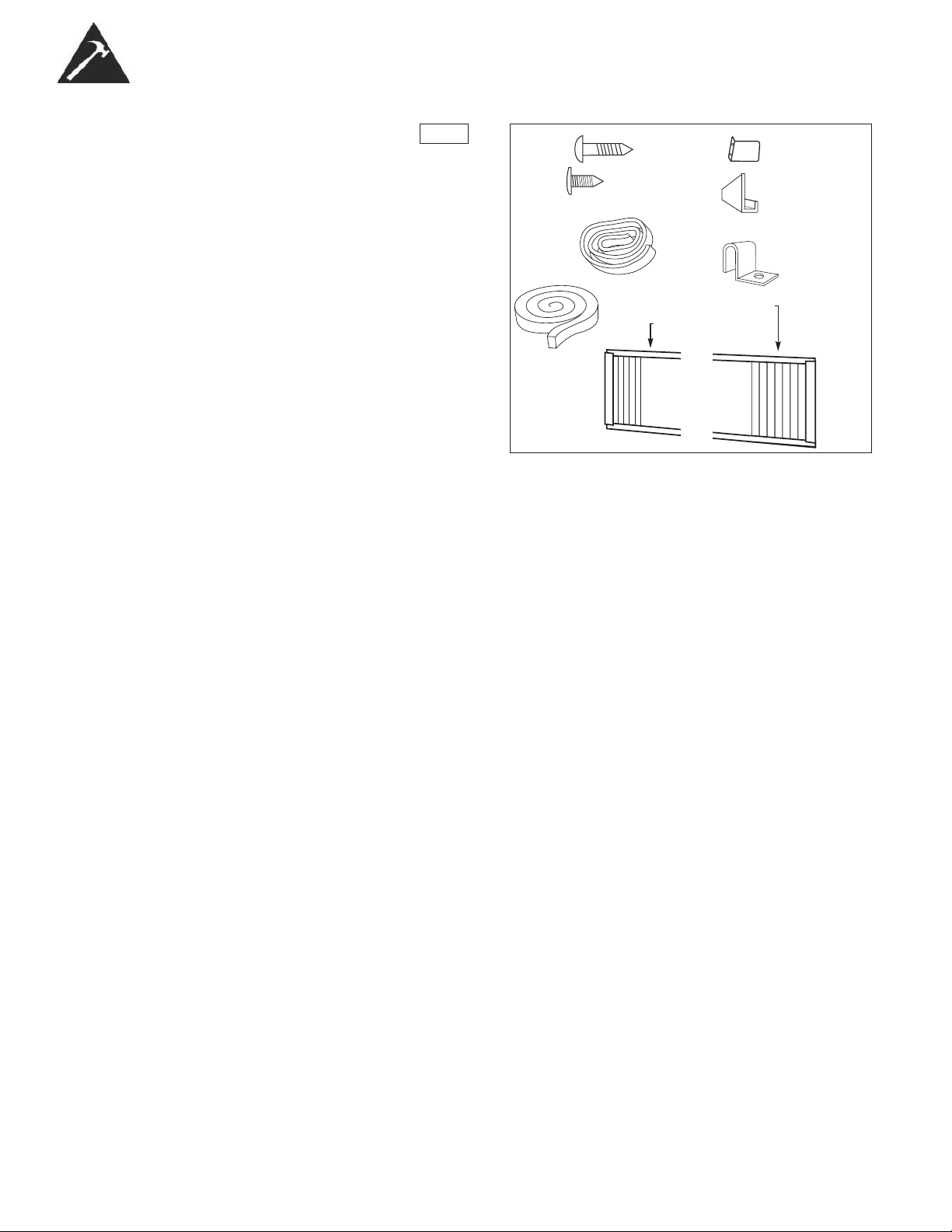
conditioner. Please check the contents of hardware kit against the corresponding model check list, prior to installation of the unit. See Fig. 1.
CAUTION
Because the compressor is located on the controls side of the unit
(left side), this side will be heavier and more awkward to manipulate. Inadequate support on control side of the unit can result in
personal injury and damage to your unit and property. Therefore, it
is recommended that you have someone assist you during the
installation of this unit.
3
Installation Instructions
INSTALLATION
HARDWARE
LOCATION
Fig. 1
Regular
Foam Seal(1)
1/2in. (13mm)
screws (7)
3/8in. (9.5mm) screws
(4) *Factory installed
on some models
Adhesive
Foam Seal(1)
Side Curtain RH (1)
Side Curtain LH (1)
Safety Lock (1)
“L” Shaped
mounting
bracket (1)
* Factory installed
on some models
Sash bracket (2)
A) This room air conditioner is designed to fit easily into a single or double
hung window. However, since window designs vary, it may be
necessary to make some modifications for safe, proper installation.
B) Make sure window and frame are structurally sound and free from dry
and rotted wood.
C) For maximum efficiency, install the air conditioner on a side of the
house or building which favours more shade than sunlight. If the unit is
in direct sunlight, it is advisable to provide an awning over the unit.
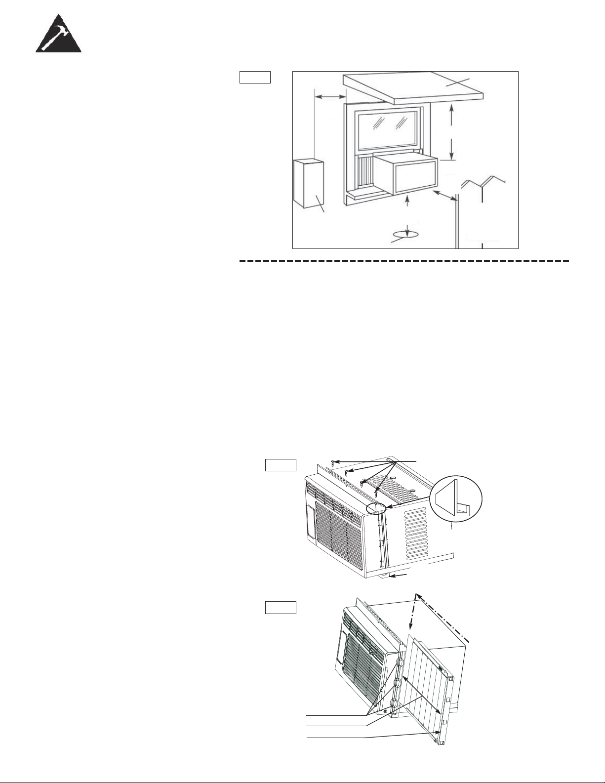
D) Provide sufficient clearance around the cabinet to allow for ample air
circulation through the unit (See Fig. 2). The rear of the unit should be
outdoors and not in a garage nor inside a building. Keep unit as far
away as possible from obstacles/obstructions and at least 30” above
the floor or ground. Curtains and other objects within a room should be
prevented from blocking the air flow.
E) Be certain the proper electrical outlet is within reach of the installation.
Use only a single outlet circuit rated at 15 amps. All wiring should be in
accordance with local and national electrical codes.
F) DO NOT install unit where leakage of combustible gas is suspected.
Your air conditioner may fail to operate in air containing oils (including
machine oils), sulfide gas, near hot springs, etc.
NOTE: Your unit is designed to evaporate condensation under normal
conditions. However, under extreme humidity conditions, excess condensation may cause the basepan to overflow to the outside. The unit should
be installed where condensation run-off cannot drip on pedestrians or
neighboring properties.
4
Installation Instructions
LOCATION
Fig. 2
20”
Min
12” Min
Side
Obstruction
Ground
30”
Min
1) Assembly of the Upper Channel to Cabinet.
Awning
20”
Min
Fence,
wall, or
other
obstacle
)DFWRU\LQVWDOOHGRQVRPH
units.)
“L” ShapedTRSChannel: InstDOOWKH“L” shapedchannelWRWKHWRSRIthe
cabinetDVshownLQFig. 3usingIRXU´screws.
2) Assembly of the Side Curtains to Cabinet.
([WHQGWKHVKXWWHUIURPWKHVKXWWHUIUDPHDQGslideLWLQWRWKHVKXWWHUtabs
RQWKHVLGHchannelRIWKHDLUconditionerDVshownLQFig. 4.
SlideWKHVKXWWHUVLQWRWKHWRS(“L” Shaped)DQGERWWRP(“U” Shaped)
channels.7KHVKXWWHUVDUHidentifiedRQIUDPHDVlefWDQGULJKW
3) Completing the Installation
&XWWKHIRDPQRQadhesive)sealingVWULSWRILWWKHDUHDRIWKHwindowsill
WKDWWKHDLUconditionerwillUHVWRQ
Fig. 3
3/8” screws
“L” shaped mounting
bracket
“U” shaped Channel
(Factory Installed)
Slide down into tabs
Fig. 4
Shutter tabs
Shutter
Shutter frame
5
Installation Instructions
3) Completing the Installation (cont)
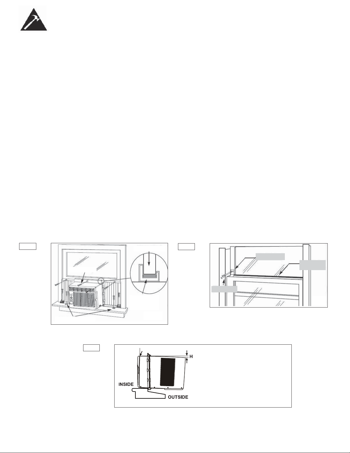
CarefullySODFHWKHDLUconditionerLQWRWKHwindowZLWKWKH“L” shaped
mountingEUDFNHWRQWRSpositionedLQIURQWRIWKHupperwindowsash.
7KHERWWRPRIWKHcabinetshouldEHpositionedRQWKH“recessed”portion
RIWKHwindowIUDPH3XOOWKHwindowdownXQWLOLWrestVMXVWbehindthe
IURQWflangeRIWKH(top) “L” shapedmountingEUDFNHW(See Fig. 5).
ExpDQGWKHVKXWWHUIUDPHVIXOO\RQHDFKVLGHDQGVHFXUHWKHWRSRIthe
IUDPHVWRWKHwindowVDVKusingRQH´VFUHZRQHDFKVLGHDQGRQHin
WKH“L” shapedmountingEUDFNHW(Fig. 5).
6HFXUHWKHVKXWWHUFODPSRQHDFKVLGHRIWKHORZHUSDUWRIWKHVKXWWHUDQG
VHFXUHWRWKHZLQGRZVLOOXVLQJRQH´VFUHZRQHDFKVLGH(Fig. 5)
3ODFHWKHsecondIRDPsealingVWULSWRILWWKHopeningbetweenWKHinside
DQGoutVLGHZLQGRZVWKHQattDFKWKHVDIHW\ORFNWRWKHoutVLGHwindow
IUDPHusingRQH´VFUHZ(See Fig. 6).
PLEASE NOTE: Window applications come in a variety of different styles. Therefore, it may
be necessary to modify or improvise your particular installation.
Fig. 5
1/2” screws
6KXWWHU clamps
&KHFNWKDWWKHDLUFRQGLWLRQHU
LVWLOWHGGRZQZDUGVWRWKHRXWsLGHDERXWWRDVVKRZQLQ
Fig. 7.
$IWHUSURSHULQVWDOODWLRQFRQGHQVHGZDWHUVKRXOGQRWdUDLQIURPWKHRYHUIORZGUDLQKROHGXULQJ
QRUPDOXVH,I\RXQRWLFHZDWHUOHDNLQJRXWFKHFNWKHDQJOHRIWLOWDQGPDNHDQ\QHFHVVDU\
DGMXVWPHQWV+RZHYHURQDYHU\KXPLGGDyZDWHUOHDNDJHFDQRFFXU±WKLVLVQRUPDO
0HDVXUHWKHWLOWDQJOHIURPWKHFDELQHW¶VHGJH7KHGLVWDQFH+VKRXOGEHDSSUR[LPDWHO\
´WR´IRU'$&(%*'%7KHGLVWDQFH+VKRXOGEHDSSUR[LPDWHO\´WR´IRU
'$&(%*'%DQG'$&2(%*'%
WLQGRZ sash
³/´ Shaped
Mounting
%UDFNHW
Fig. 6
´ screw
6DIHW\ Lock
)RDP
Seal
(adhesive)
Fig. 7 Measure the tilt angle from the cabinet’s edge
: approximately 3/4” to 1” for DAC080EB2GDB
H: approximately 1” to 1 3/8” for DAC100EB2GDB
WINDOW
6
DAC120EB2GDB
Operating Instructions
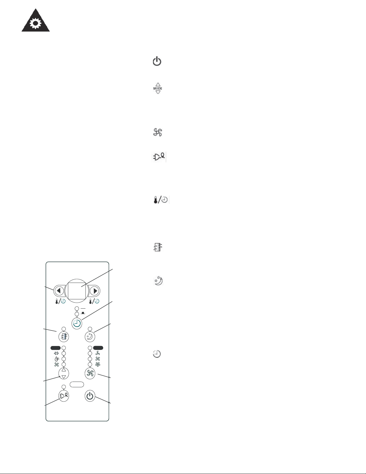
KEY PAD FEATURES
LED DISPLAY : Displays the following information independently - Set
Temperature, Ambient RoomTemperature and Auto Timer On/Off settings.
POWER: Turns unit On/Off.
NOTE: The unit will automatically launch the Energy Saver function when it is
in Cool, Dry, and Auto modes (only Auto-Cool and Auto-Fan modes).
MODE: Allows you to scroll through and select the desired operating
mode:
Cool , Dry , Fan Only and *Auto. The selected mode will be denoted by the adjacent indicator light. * ‘Auto’ is a pre-set factory program that
automatically defines the mode (Cool or Dry) and fan speed, based on the
set temperature. The unit will automatically launch the Energy Saver function
FAN SPEED: Select from four different fan settings: Low , Medium,
High and Auto during Cool and Fan Only mode. Please note, during ‘Dry’
mode the fan speed is automatically defined.
ENERGY SAVER: Automatically cycles the fan on and off while the
compressor is not in use. This function is available in Cool, Dry, and Auto
modes (only Auto-Cool and Auto-Fan modes). The fan will continue to run for
3 minutes after the compressor shuts off. The fan then cycles on for 2
minutes at 10 minute intervals, until the room temperature is above the set
temperature. At this point, the compressor turns back on and cooling starts.
TEMP / TIMER CONTROL: Used to increase or decrease
the Temperature setting in 1°C / °F increments, and Auto-Timer On/Off settings in 30min./1hr. increments. Note: This appliance allows you select the
temperature scale to be displayed in either “Celsius” or “Fahrenheit”
according to your preference.To change the temperature scale displayed
on the electronic display, press both the “Temp/Timer”adjust arrows simultaneously to alternate between “Celsius” & “Fahrenheit”.
Temp / Timer
Control
Check
Filter
Mode
Selector
Energy
Saver
Auto
MODE
68
Auto
LED
Display
Auto
Timer
Sleep
Mode
Fan
Speed
Power
Button
CHECK FILTER: The adjacent indicator light will illuminate as a
reminder to clean the air conditioner filter (see page 14). Once the filter has
been cleaned and replaced, depress the Check Filter button in order to
resume operation.
SLEEP MODE:
In this mode, the selected temperature
will increase
(when in cooling mode) by 2°F one half-hour after Sleep mode has been
selected. The temperature will then increase by another 2°F after an additional half hour. This new temperature will be maintained for 6 hours before
returning to the originally selected temperature. This ends the Sleep mode
and the unit will continue to operate as originally programmed. The Sleep
mode program can be cancelled at any time during operation by pressing the
Sleep button again.
AUTO-TIMER: Used to initiate the Auto On/ Auto Off timer.
While the Air Conditioner is off (Auto-On):
1) Press the Auto-Timer button once and the adjacent Auto-On indicator
light will illuminate.
2) Use the Temp/Timer control cursors to select a delayed On time of
up to 24 hours.
3) Select the appropriate mode under which you want the unit to operate
(Auto-Cool-Dry-Fan Only)
4) Select the fan speed setting.
5) The time you selected will appear in the LED display.
7
Operating Instructions
While the Air Conditioner is on (Auto-Off):
1) Press the Auto-Timer button twice and the adjacent Auto-Off indicator
light will illuminate.
2) Use the Temp/Timer control cursors to select a delayed Off time of up
to 24 hours.
3) The time you selected will appear in the LED display. The Auto On and
Auto Off timer can operate during the same program by defining the
Auto-Off parameters immediately after the Auto On parameters.The
Auto-Timer may be cancelled at any time by turning the unit On/Off.
For example,if you want to let the machine on one hour later and last
for one hour and then stop,set auto on “1” and auto off “2”.
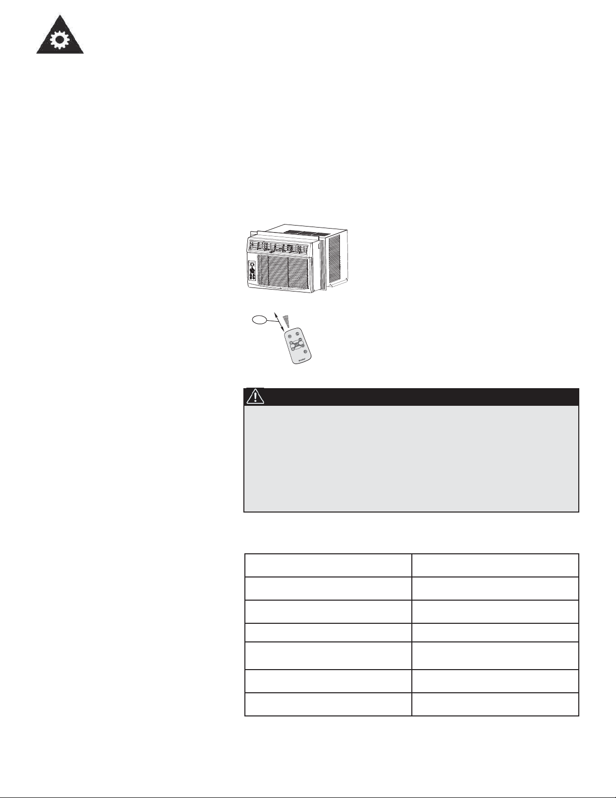
USING THE REMOTE
CONTROL
Location of the remote controller.
• Use the remote controller within a distance of 8
meters from the appliance, pointing it towards
the receiver. Reception is confirmed by a beep.
8m
ab
l
j
c
c
l
L
k
l
jm
b
k
q
t
l
a
m
j
b
q
m
r
d
k
f
t
p
o
b
j
f
q
k
^
c
m
b
b
i
p
CAUTION
• The air conditioner will not operate if curtains,doors or other
materials block the signals from the remotecontroller to the
indoor unit.
• Prevent any liquid from falling into the remote controller. Do not
expose the remote controller to direct sunlight or heat.
• If the infrared signal receiver on the indoor unit is exposed to
direct sunlight, the air conditioner may not function properly. Use
curtains to prevent the sunlight from falling on the receiver.
• If other electrical appliances react to the remote controller, either
move theseappliances or call the service depot.
REMOTE CONTROLLER
SPECIFICATIONS
Model
Rated Voltage
Battery Type
Battery Quantity
Lowest Voltage of
CPU Emitting Signal
Signal Receiving Range
Environment
8
R15B
3.0V
Button cell: CR2025
1pcs
2.0V
8m
-5°C to 60°C

Operating Instructions
REMOTE
CONTROLLER
BUTTONS
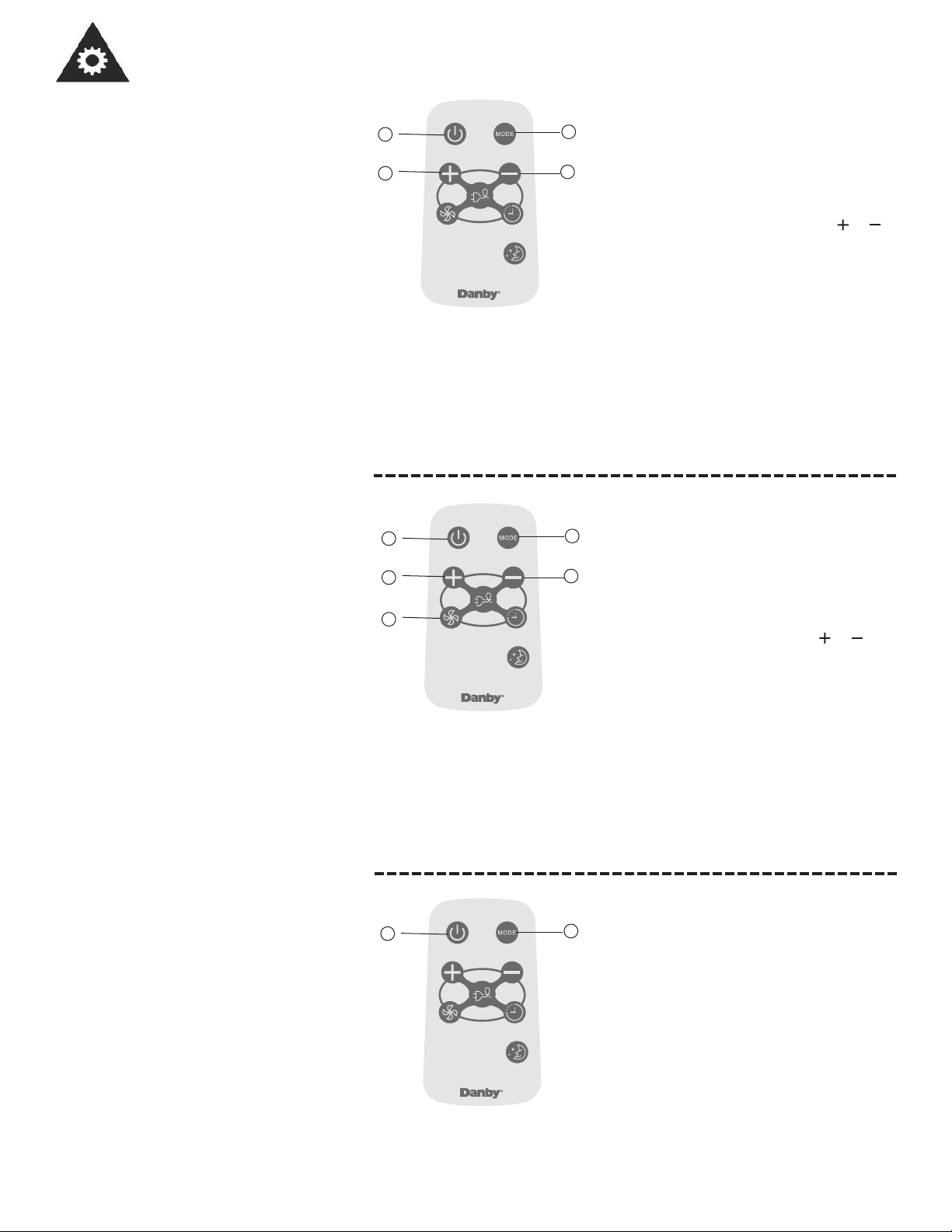
ON/OFF button
Operation starts when
this button is pressed
and stops when the
button
NOTE:The unit will automa-
tically launch the Energy
Saver function when it is in
Cool, Dry, and Auto modes
(Auto-Cool and Auto-Fan
modes).
is pressed again.
TEMP UP button
Push this button to
increase the temperature setting in 1°C
increments to 30°C.
FAN button
Used to select the fan
speed in four steps:
LOW
MED
HIGH AUTO
MODE button
Each time you press
this button, a mode is
selected in a sequence
that consists of Auto,
Cool, Dry, Fan, and
back to Auto.
TEMP DOWN button
Push this button to
decrease the indoor
temperature setting in
1°C increments to 17°C.
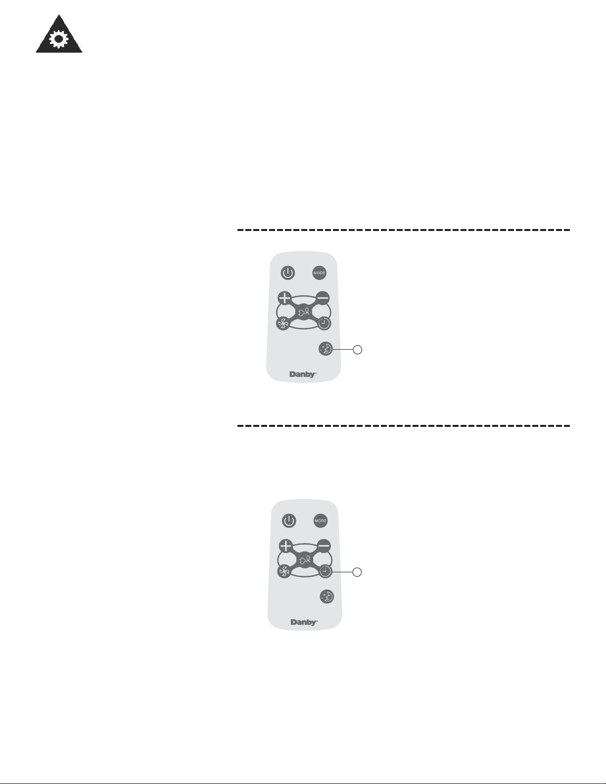
TIMER button
Push this button to
activate the “Auto
Start” or “Auto Stop”
program from 0-24
(0.5/1 hour increments)
hours
ENERGY SAVER
button
Press this button to
activate the Energy saving mode. Press it again
to
stop the function.
This function is available in
Cool, Dry, and Auto modes
(only Auto-Cool and AutoFan modes).
Model:
R15B
SLEEP button
Press this button to
activate the Sleep
mode. This function is
available in Cool, and
Auto modes only, and
maintains the most
comfortable temperature
for you.
9

Operating Instructions
USING THE REMOTE
CONTROLLER
BUTTONS
AUTO OPERATION
Ensure the unit is plugged in and power is
2
1
3
available.
1) Press the ON/OFF button to start the air
3
conditioner.
2) Press the mode button and select
AUTO.
3) Press the TEMP / button to
set the desired temperature. The
temperature can be set within a range of
17°C to 30°C in 1°C increments.
NOTE
1. In the Auto mode, the air conditioner can logically choose the mode of
Cool, Fan, Dehumidifying by sensing the difference between the
actual ambient room temperature and the set temperature on the
remote controller.
2. In the Auto mode, you cannotchangethe fan speed. It has already been
automatically controlled.
3. If the Auto mode is not comfortable for you, the desired mode can be
selected manually.
COOLING/ FAN OPERATION
Ensure the unit is plugged in and power is
1
2
available.
1) Press the ON/OFF button to start the air
3
3
conditioner.
2) Press the MODE button to select Cool mode.
4
3) Press the TEMP / button to
set the desired temperature. The
temperature can be set within a range of
17°C to30°C in 1°C increments.
4) Press the FAN button to select the fan
speed
in four steps-Low, Med, High,or
AUTO.
NOTE:
In the Fan mode, the setting temperature is not displayed in the remote
controller and you are not able to control the room temperature either. In
this case, only step 1, 2 and 4 may be performed.
DEHUMIDIFYING OPERATION
Ensure the unit is plugged in and power is
1
2
available.
1) Press the ON/OFF button to start the air
conditioner.
2) Press the MODE button to select
Dehumidifying mode.
NOTE:
In the Dehumidifying mode, you cannotchangethe fan speed. It has
already been automatically controlled.
10
Operating Instructions
USING THE REMOTE
CONTROLLER
BUTTONS
SLEEP OPERATION
In this mode, the selected temperature will
increase (when in cooling mode) by 2°F one
half-hour after sleep mode has been selected.
The temperature will then increase by another
2°F after an additional half-hour.
This new temperature will be maintained for 6
hours before returning to the originally selected
temperature. This ends the Sleep mode and the
unit will continue to operate as originally prog-
1
rammed.
The Sleep mode program can be cancelled at
any time during operation by pressing the Sleep
button again.
TIMER OPERATION
Pressing the TIMER button can set the
Auto-start and Auto-stop time of the unit.
NOTE:
To set Auto-start time, the unit must be in
the OFF position.
To set Auto-stop time, the unit must be in
the ON postion.
To set the Auto-start time.
1. Push the TIMER button when the unit is
1
off; only the Auto-start feature can be set.
2. Keep pressing the TIMER button. Each
press will increase the selected time by
0.5 hour increments. When the selected time
has added up to 10 hours,each press will
increase the selected time by 1 hour
increments, up to 24 hours.
3. The time can be set in the range of 0 - 24
hours.
4. After the desired time has been selected, wait
for about 10 seconds, until the setting temperature reappears in the display window
of the air conditioner. This indicates that
the program has been set.
11

Operating Instructions
USING THE REMOTE
CONTROLLER
BUTTONS
TIMER OPERATION
To set the Auto-start time.
1) Push the TIMER button when the unit is
operational; only the Auto-stop feature
can be set.
2) Keep pressing the TIMER button. Each
1
NOTE:
To cancel the TIMER setting, push the TIMER button until “0 hours” is
displayed on the LCD window of the air conditioner.
1
press will increase the selected time by
1 hour increments, up to 24 hours.
3) The time can be set in a range of 0 - 24
hours.
4) After the desired time has been selected,
wait for about 10 seconds, until the setting
temperature reappears in the display window
of the air conditioner. This indicates that
the program has been set.
ENERGY SAVER OPERATION
This function is available in Cool, Dry, and Auto
modes (only Auto-Cool and Auto-Fan modes).
The fan will continue to run for 3 minutes after
the compressor has shut off. The fan then cycles
on for 2 minutes at 10 minute intervals, until the
room temperature is above the set temperature.
At this point, the compressor turns back on and
cooling starts.
12

Operating
Instructions
CHANGING THE
BATTERIES ON THE
REMOTE
Protect the remote control from high
temperatures, and keep it away from
radiation exposure.
Keep the control panel receiver out of
direct sunlight.
The remote controller is powered by
one button cell housed in the rear part
and protected by a cover. Remove the
button cell according to the arrow
marked at the back of the remote
controller.
1
1. Slightly press “A” position
according to the number 1
arrow direction by your
`oOMOR
oOMO R
`
1
2
2
+
1
1
A
forefinger.
2
2. Press “B” position and pull it
according to the number 2
arrow direction by your
thumb.
2
3. The above step 1 and 2
+
should be done simultaneously
to slide the button cell out.
B
If the remote control will not be used for
extended periods of time (vacations etc.),
batteries should be removed.
The remote operates within a range of 8
meters (26 ft.) from the receiver located
inside the main unit.Any obstruction between
the receiver and remote may cause signal
This Class B digital apparatus complies with
the Canadian ICES-003 standard. CAN ICES-3 (B)
interference, limiting the ability to program
the main unit.
NOTE: This equipment has been tested and found to comply with the limits for a Class B digital
device, pursuant to Part 15 of the FCC Rules. These limits are designed to provide reasonable
protection against harmful interference in a residential installation. This equipment generates, uses
and can radiate radio frequency energy and, if not installed and used in accordance with the
instructions, may cause harmful interference to radio communications. However, there is no
guarantee that interference will not occur in a particular installation. If this equipment does cause
harmful interference to radio or television reception, which can be determined by turning the
equipment off and on, the user is encouraged to try to correct the interference by one or more of the
following measures:
--Reorient or relocate the receiving antenna
--Increase the separation between the equipment and receiver
--Connect the equipment into an outlet on a circuit different from that to which the receiver is
connected
--Consult the dealer or an experienced radio/TV technician for help
Changes or modifications not approved by the party responsible for FCC compliance could void the
user’s authority to operate the equipment.
This appliance complies with Part 15 of the FCC Rules. Operation is subject to the following two
conditions:
1) This device may not cause harmful interference.
2) This device must accept any interference received, including interference that may cause
undesired operation.
13

Care and Maintenance
NOTE: In order to avoid electric shock, please turn
off the A/C and unplug the plug before mainte-
CLEANING
When cleaning the air conditioner be sure to disconnect the power cord from the electrical outlet.
1. DO NOT use gasoline, benzene, thinner, or any other chemicals to clean this unit, as these substances may cause
damage to the ¿ nish and deformation of plastic parts.
2. Never attempt to clean the unit by pouring water directly over any of the surface areas, as this will cause deterioration
of electrical components and wiring insulation.
AIR FILTER
If the air ¿ lter becomes clogged with dust, air À ow is obstructed and reduces ef¿ ciency. The air ¿ lter should be cleaned
every 2 weeks.
AIR FILTER REMOVAL:
The air ¿ lter is located behind the air intake front grill. To remove the air ¿ lter, grasp the ¿ lter handle on the front of the grill
and slide it out to the right.
To reinstall the air ¿ lter, reverse the above procedures. The air ¿ lter must be vacuumed or washed by hand in warm water.
Dry thoroughly before re-installing.
nance or repair.
CLEANING AIR FILTER:
1. Use a vacuum cleaner with soft brush attachment.
2. Wash the ¿ lter in lukewarm water below 40°C (104°F). To get best results, wash with soapy water or a neutral clean-
ing agent.
3. Rinse the ¿ lter with clean water and dry thoroughly before re-installing.
IMPORTANT
DO NOT forget to install the air ¿ lter. If the air conditioner is left to operate without the air
¿ lter, dust is not removed from the room air and may result in machine failure. When the
air inlet grill and cabinet are dirty, wipe with lukewarm water (below 40°C). Use of a mild
detergent is recommended.
END OF SEASON CARE
1. Operate the fan alone for half a day to dry out the inside of the unit.
2. Turn off power and remove plug from wall socket.
3. Clean ¿ lter.
4. Store (covered) air conditioner in a dry location.
CAUTION
When installing and/or removing the air conditioner from the window, ensure that caution
is taken to prevent it from falling backward. It is recommended that installation or removal
of the air conditioner is done with assistance, to prevent injury to persons or damage to the
unit or property.
DISPOSAL
Check for local regulatory compliance regarding the approved and safe disposal of this appliance.
14

Troubleshooting
Occasionally a problem may arise that is minor in nature, and a service call may not be neccessary. Use this troubleshooting guide for a possible solution. If the unit continues to operate improperly, call an authorized service depot or
Danby`s Toll Free Number 1-800-263-2629 for assistance.
NOITULOSESUAC ELBISSOPMELBORP
Air conditioner will
not operate
• No power to the unit • Check connection of power cord to power
source.
• Check fuse or circuit breaker.
• The power cord “RESET” button must
always be pushed in (engaged) for correct operation.
Inef¿ cient or no
cooling
Odors • Formation of mold, mildew, or algae
Water dripping
outside
Water dripping inside • Unit is not properly angled to allow
Ice or frost build-up • Low outside temperature • When outdoor temperature is approximately
• Dirty air ¿ ria ecalper/naelC •retl ¿ lter
• Unit size inappropriate for application • Check with dealer to determine proper unit capacity for application
• Blocked air À servuol roodtuo ro llirg m
• Power interruption, settings changed
too quickly, or compressor overload
tripped
• Inadequate support • Provide additional support to unit
on wet surfaces
• Hot and humid weather • Condensation run-off is normal under these
water to drain outside
• It is an extremely humid day • On an extremely humid day, this effect is expect-
• Unit air ¿ lter is dirty • Remove and clean ¿ lter
• Turn the unit off and wait 5 minutes before attempting to restart
• Clean unit thoroughly
• Place algaecide tablet in base pan
conditions.
• Unit must be installed on an angle for proper
condensation run-off. Check the unit and make
any adjustments.
ed. No action required.
18.3°C (65°F) or below, frost may form when
unit is in cooling mode. Switch unit to FAN (only)
operation until frost melts.
orf noitcurtsbo evomeR •wo
strap esool nethgiT •strap esooL •tinu ysioN
NOTES:
1. If circuit breaker is tripped repeatedly, or fuse is blown more than once, contact a quali¿ ed technician.
2. When the unit is installed using proper installation steps, the unit is properly tipped toward the outdoors to allow for
condensation run-off.
15

LIMITED IN-HOME APPLIANCE WARRANTY
LIMITED IN-HOME APPLIANCE WARRANTY
This quality product is warranted to be free from manufacturer’s defects in material and workmanship, provided that the unit is used under the normal operating
This quality product is warranted to be free from manufacturer’s defects in material and workmanship, provided that the unit is
conditions intended by the manufacturer.
used under the normal operating conditions intended by the manufacturer.
This warranty is available only to the person to whom the unit was originally sold by Danby Products Limited (Canada) or Danby Products Inc. (U.S.A.) (hereafter
This warranty is available only to the person to whom the unit was originally sold by Danby Products Limited (Canada) or
“Danby”) or by an authorized distributor of Danby, and is non-transferable.
Danby Products Inc. (U.S.A.) (hereafter “Danby”) or by an authorized distributor of Danby, and is non-transferable.
TERMS OF WARRANTY
Plastic parts, are warranted for thirty (30) days only from purchase date, with no extensions provided.
Plastic parts, are warranted for thirty (30) days only from purchase date, with no extensions provided.
First Year
First Year
To obtain
Service
To obtain
Service
Boundaries of
Boundaries of
In Home Service
In Home Service
During the first twelve (12) months, any functional parts of this product found to be defective, will be
repaired or replaced, at warrantor’s option, at no charge to the ORIGINAL purchaser.
During the rst twelve (12) months, any functional parts of this product found to be defective, will be repaired or replaced, at warrantor’s
option, at no charge to the ORIGINAL purchaser.
Danby reserves the right to limit the boundaries of “In Home Service” to the proximity of an Authorized
Service Depot. Any appliance requiring service outside the limited boundaries of “In Home Service” ,it
Danby reserves the right to limit the boundaries of “In Home Service” to the proximity of an Authorized Service Depot. Any app liance
will be the consumer’s responsibility to transport the appliance (at their own expense) to the original
requiring service outside the limited boundaries of “In Home Service” , it will be the consumer’s responsibility to transport the appliance (at
retailer (point of purchase) or a service depot for repair. See “Boundaries of In Home Service” below.
their own expense) to the original retailer (point of purchase) or a service depot for repair. See “Boundaries of In Home Serv ice” below.
Contact your dealer from whom your unit was purchased, or contact your nearest authorized Danby
Contact your dealer from whom your unit was purchased, or contact your nearest authorized Danby service depot, where service
service depot, where service must be performed by a qualified service technician. If service is performed
must be performed by a qualied service technician.
on the units by anyone other than an authorized service depot, or the unit is used for commercial
If service is performed on the units by anyone other than an authorized service depot, or the unit is used for commercial appli cation, all
application, all obligations of Danby under this warranty shall be void.
obligations of Danby under this warranty shall be void.
If the appliance is installed in a location that is 100 kilometers (62 miles) or more from the nearest
If the appliance is installed in a location that is 100 kilometers (62 miles) or more from the nearest service center your unit must be
service center your unit must be delivered to the nearest authorized Danby Service Depot, as service
delivered to the nearest authorized Danby Service Depot, as service must only be performed by a technician qualied and certif ied for
must only be performed by a technician qualified and certified for warranty service by Danby. Transpor-
warranty service by Danby. Transportation charges to and from the service location are not protected by this warranty and are t he
tation charges to and from the service location are not protected by this warranty and are the responsi-
responsibility of the purchaser.
bility of the purchaser.
TERMS OF WARRANTY
Nothing within this warranty shall imply that Danby will be responsible or liable for any spoilage or damage to food or other c ontents of this appliance, whether due
Nothing within this warranty shall imply that Danby will be responsible or liable for any spoilage or damage to food or other
to any defect of the appliance, or its use, whether proper or improper.
contents of this appliance, whether due to any defect of the appliance, or its use, whether proper or improper.
EXCLUSIONS
EXCLUSIONS
Save as herein provided, by Danby, there are no other warranties, conditions, representations or guarantees, express or
Save as herein provided, Danby, there are no other warranties, conditions, representations or guarantees, express or implied, m ade or intended by Danby or its
implied, made or intended by Danby or its authorized distributors and all other warranties, conditions, representations or
authorized distributors and all other warranties, conditions, representations or guarantees, including any warranties, conditio ns, representations or guarantees
guarantees, including any warranties, conditions, representations or guarantees under any Sale of Goods Act or like legislation
under any Sale of Goods Act or like legislation or statue is hereby expressly excluded. Save as herein provided, Danby shall no t be responsible for any damages
or statute is hereby expressly excluded. Save as herein provided, Danby shall not be responsible for any damages to persons
to persons or property, including the unit itself, howsoever caused or any consequential damages arising from the malfunction o f the unit and by the purchase of
or property, including the unit itself, howsoever caused or any consequential damages arising from the malfunction of the unit
the unit, the purchaser does hereby agree to indemnify and hold harmless Danby from any claim for damages to persons or propert y caused by the unit.
and by the purchase of the unit, the purchaser does hereby agree to indemnify and hold harmless Danby from any claim for
damages to persons or property caused by the unit.
No warranty or insurance herein contained or set out shall apply when damage or repair is caused by any of the following:
1) Power failure.
No warranty or insurance herein contained or set out shall apply when damage or repair is caused by any of the following:
1) Power failure.
2) Damage in transit or when moving the appliance.
2) Damage in transit or when moving the appliance.
3) Improper power supply such as low voltage, defective house wiring or inadequate fuses.
3) Improper power supply such as low voltage, defective house wiring or inadequate fuses.
4) Accident, alteration, abuse or misuse of the appliance such as inadequate air circulation in the room or abnormal operating con ditions
4) Accident, alteration, abuse or misuse of the appliance such as inadequate air circulation in the room or abnormal operating
conditions (extremely high or low room temperature).
5) Use for commercial or industrial purposes (ie. If the appliance is not installed in a domestic residence).
6) Fire, water damage, theft, war, riot, hostility, acts of God such as hurricanes, floods etc.
7) Service calls resulting in customer education.
8) Improper Installation (ie. Building-in of a free standing appliance or using an appliance outdoors that is not approved for
outdoor application). Proof of purchase date will be required for warranty claims; so, please retain bills of sale. In the event
Proof of purchase date will be required for warranty claims; so, please retain bills of sale. In the event warranty service is required, present this document to our
warranty service is required, present this document to our AUTHORIZED SERVICE DEPOT.
AUTHORIZED SERVICE DEPOT.
(extremely high or low room temperature).
5) Use for commercial or industrial purposes (ie. If the appliance is not installed in a domestic residence).
6) Fire, water damage, theft, war, riot, hostility, acts of God such as hurricanes, oods etc.
7) Service calls resulting in customer education.
8) Improper Installation (ie. Building-in of a free standing appliance or using an appliance outdoors that is not approved for out door application).
GENERAL PROVISIONS
GENERAL PROVISIONS
Danby Products Limited
Danby Products Limited
PO Box 1778, Guelph, Ontario, Canada N1H 6Z9
PO Box 1778, Guelph, Ontario, Canada N1H 6Z9
Telephone: (519) 837-0920 FAX: (519) 837-0449
Telephone: (519) 837-0920 FAX: (519) 837-0449
Warranty Service
Warranty Service
In-home
In-home
1-800-263-2629
1-800-263-2629
07/13
04/09
Danby Products Inc.
PO Box 669, Findlay, Ohio, U.S.A. 45840
Telephone: (419) 425-8627 FAX: (419) 425-8629
PO Box 669, Findlay, Ohio, U.S.A. 45840
Telephone: (419) 425-8627 FAX: (419) 425-8629
Danby Products Inc.

BIENVENUE
Bienvenue dans la famille Danby. Nous sommes fi ers de la qualité de nos produits et nous croyons fermement au service
par une assistance fi able. Vous découvrirez au travers de ce quide, facile d’utilisation et vous en aurez la confi rmation par
notre service d’assistance à la clientèle. Mais ce qui est encore mieux, vous pourrez bénéfi cier de ces valeurs à chaque
utilisation de votre appareil. Ceci est important parce que votre nouvel appareil fera partie de votre famille pour longtemps.
À titre de référence, vous pouvez agrafer à cette page une copie de votre fi che d’achat de l’appareil. Inscrivez les rensei-
gnements suivants fournis (sur la plaque signalétique du fabricant sur le côté droit de l’appareil au-dessus du cordon
d’alimentation). Vous aurez besoin de ces renseignements si vous contactez un représentant du service à la clientèle.
S’il vous plaît écrivez informations ci-dessous; ces renseignements seront nécessaires si votre appareil a besoin
d’entretien ou pour les demandes de renseignements généraux. Pour bénéfi cier d’une opération de maintenance
ou dépannage, le reçu original sera exigé.
REMARQUE: CET APPAREIL N’A PAS ÉTÉ CONÇU POUR UNE INSTALLATION À TRAVERS UNE PAROI.
Numéro de modèle :
Numéro de série :
Date d’achat :
BESOIN D’ASSISTANCE ?
Veuillez trouver quelques conseils avant de faire appel à nos
services, cela nous aidera à mieux vous servir:
Lisez ce guide:
Il comprend des instructions pour l’utilisation et l’entretien
adapté de votre unité.
Si votre nouvel appareil est endommagé :
Contactez immédiatement le revendeur (ou le fabricant).
Gagnez du temps et de l’argent :
Avant de faire appel à nos services, consultez à nouveau
la section « “Dépannage ». Cette section vous aidera à
solutionner des problèmes courants.
Si une réparation est nécessaire, ne vous inquiétez pas, la
solution est au bout de l’appel téléphonique.
Tel: 1-800-26-
(1-800-263-2629)
AVERTISSEMENT :
Une fi che de mise à la terre mal branchée peut entraîner un risque d’incendie, de
choc électrique ou de blessures aux personnes qui utilisent l’appareil. Si vous
n’êtes pas certain que l’appareil est correctement mis à la terre, consultez un
préposé du service qualifi é.
17

Consignes de sécurité importantes
LISEZ TOUTE L'INFORMATION DE SÉCURITÉ AVANT UTILISATION
POUR VOTRE SÉCURITÉ: Lire attentivement ces instructions avant d'utiliser l'appareil.
SPECIFICATIONS
ELECTRIQUES
1) Tous les câblages doivent être conformes aux codes électriques locaux
et nationaux et doivent être installés par un électricien qualifié. Si vous
avez la moindre question au sujet des instructions ci-dessous,
contactez un électricien qualifié.
2) Vérifiez la fourniture d’alimentation électrique disponible et résolvez
tout problème de câblage AVANT d’installer et de faire fonctionner cet
appareil.
3) Ce climatiseur à 115V utilise 5 ampères ou moins de puissance
nominale et peut être utilisé dans toute prise de courant domestique de
but général adéquatement câblée. Reportez-vous au Tableau 1 pour
les spécifications concernant le circuit de dérivation individuel.
4) Pour votre sécurité et votre protection, cet appareil est mis à la masse
par la fiche du cordon d’alimentation lorsqu’elle est branchée dans une
prise murale qui lui correspond. Si vous n’êtes pas certain que votre
prise de courant murale est mise à la masse adéquatement, veuillez
consulter un électricien qualifié.
5) La prise murale doit correspondre à la fiche à 3 broches sur le cordon
de service fourni avec l’appareil. N’utilisez PAS de fiches d’adaptation.
Voir Tableau 2 pour les renseignements sur les prises de courant et les
fusibles. S’il est nécessaire d’utiliser une rallonge électrique pour
brancher votre climatiseur, utilisez une rallonge électrique approuvée
pour «climatiseur», exclusivement (disponible dans la plupart des
magasins locaux de quincaillerie).
6) La plaque signalétique sur l’appareil contient des données électriques
et techniques; elle se trouve sur le côté droit de l’appareil, au-dessus du
cordon d’alimentation.
TABLEAU 1 DAC080EB2GDB
Circuit de distribution individuel suggéré
Ampères de plaque d’identification Calibre de fil A WG*
6.2 16
AWG – American Wire Gauge (Calibre de fil américain)
*Basé sur le fil en cuivre à une température nominale de 60°C
TABLEAU 1 DAC100EB2GDB
DAC120EB2GDB
Circuit de distribution individuel suggéré
Ampères de plaque d’identification Calibre de fil A WG*
7.7 à 9.5 14
AWG – American Wire Gauge (Calibre de fil américain)
*Basé sur le fil en cuivre à une température nominale de 60°C
TABLEAU 2
Types de fusibles et de réceptacles
521elanimon noisneT
51serèpmA
Prise de courant
51elbisuf ed étisnetnI
Fusible temporisé Type fiche
(ou disjoncteur de circuit)
18

Consignes de sécurité importantes
LISEZ TOUTE L'INFORMATION DE SÉCURITÉ AVANT UTILISATION
POUR VOTRE SÉCURITÉ: Lire attentivement ces instructions avant d'utiliser l'appareil.
L’ÉCONOMIE DE
L’ÉNERGIE
Caractéristiques
Commutateur pour ventilation d’air frais
(seulement disponible sur les modèles
DAC100EB2GDB et
DAC120EB2GDB)
Sortie d’air
intérieure
Votre appareil ménager Danby est conçu pour l’efficacité en
économie de l’énergie. Pour le rendement maximal, observer les recom-
mandations qui suivent.
1) Choisir un réglage du thermostat qui répond à vos besoins de confort et le
laisser au réglage choisi.
2) Le filtre à air est très efficace pour éliminer les particules qui flottent dans
l’air. Conserver le filtre à air propre en tout temps. (Habituellement, il faut
nettoyer le filtre tous les 2 semaines. Cela peut varier selon la qualité d’air.)
3) Utiliser des draperies, des rideaux ou des stores pour prévenir la
pénétration et le réchauffement de la pièce par les rayons directs du soleil,
mais ne pas permettre la restriction de la circulation d’air autour de l’unité
par les draperies ou les rideaux.
4) Activer votre climatiseur avant que la température de l’air extérieur ne soit
très chaude. Ceci préviendra une période initiale d’inconfort avant que
l’unité ne puisse refroidir la pièce.
5) Quand les températures externes sont suffisamment froides, placer le
climatiseur hors de service et utiliser le MODE DE VENTILATEUR à la
position HAUTE, MOYENNE ou BASSE. Ceci fait circuler l’air à l’intérieurde la
pièce pour fournir un certain confort de climatisation en utilisant moins
d’électricité.
Caisson
Tableau de
commande
Entrée d’air
intérieure
Installation
RISQUE DE CHOC ÉLECTRIQUE
Pour éviter la possibilité de
blessures corporelles, débrancher
l’alimentation de courant à l’unité
avant d’entreprendre l’installation
ou le service.
REMARQUE: Votre climatiseur de
chambre a été conçu pour une installation facile dans une fenêtre à châssis à
guillotine simple ou double. Cet appareil
n’a pas été conçu pour des fenêtres verticales (de type coulissant) ou pour être
installé à travers une paroi.
Entrée d’air
extérieure
Filtre à air
OUTILS NÉCESSAIRES POUR INSTALLATION
Tournevis à tête Phillips et plate
Perceuse électrique Mèche de 1/8 po de diam.
Crayon
Ruban à mesure
Ciseaux
Clé réglable
REMARQUE: Conservez le carton d’expédition et le matériel d’emballage pour
futur entreposage ou transport de l’appareil. Ôtez l’appareil du carton, le sac en
plastique qui contient la trousse de quincaillerie nécessaire pour l’installation de
votre climatiseur. Veuillez vérifier le contenu de la trousse de quincaillerie d’installation en le comparant à la liste de vérification du modèle correspondant, et
ce, avant l’installation de l’appareil. Voir Fig. 1.
19

Installation
OUTILS NÉCESSAIRES
POUR INSTALLATION
MISE EN GARDE
Comme le compresseur se trouve du côté des commandes de l’unité
. Un
soutien inapproprié du côté des commandes de l’appareil peut causer
des blessures et endommager l’appareil et d’autres biens mobiliers.
C’est pourquoi il est recommandé que quelqu’un vous aide au cours de
l’installation de cet appareil.
Fig. 1
Scellement
mousse
(1)
régulière
Vis de 1/2po
(13mm) (7)
Vis de 3/8po (9.5mm)
(4) *Préinstallé sur
certain modèles
Scellement
mousse (1)
adhésif
Rideau latéral droit (1)
Rideau latéral
gauche (1)
Serrure de
Sûreté (1)
Canal supérieur
(1) *Préinstallé
sur certain
modèles
Support de
fermeture (2)
ENDROIT
A) Ce climatiseur pour chambre a été conçu pour être installé facilement dans
une fenêtre à châssis à guillotine simple ou double. Cependant, comme le
design de la fenêtre peut varier, it peut être nécessaire d’y faire quelques
modifications pour une installation sécuritaire et appropriée.
B) Assurez-vous que la fenêtre et son châssis sont structurellement solides et
exempts de bois sec et pourri.
C) Pour un maximum d’efficacité, installez le climatiseur sur le côté de la
maison ou de l’immeuble qui se trouve plus souvent à l’ombre qu’au soleil.
Si l’appareil est directement sous les rayons du soleil, installer un auvent
pour protéger l’unité.
D) Laissez suffisamment d’espace libre autour du caisson pour permettre une
ample circulation d’air à travers l’appareil. Voir Fig. 2. L’arrière de l’appareil
doit donner sur l’extérieur de la maison et non pas dans un garage ou à
l’intérieur d’un immeuble. T enez l’appareil aussi loin que possible de tout
obstacle ou obstruction et à au moins 30 po au-dessus du plancher ou du
sol. Il ne faut pas que les rideaux ou d’autres objets à l’intérieur de la pièce
puissent bloquer le flux d’air.
E) Assurez-vous que la prise électrique appropriée se trouve à la portée de
l’installation. N’utilisez qu’un circuit à prise unique calculé à 15 ampères. Tout
le câblage doit être conforme aux codes électriques locaux et nationaux.
F) N’insallez PASl’app areil à un endroit où on soupçonne une fuite de gaz
combustibles. Votre climatiseur peut tomber en panne dans une atmosphère
qui contient des huiles (y compris des huiles pour machines), des gaz
sulfurés, ou s’il est près de sources d’eau chaude, etc.
20

Installation
ENDROIT
VREMARQUE: otre appareil a été conçu pour que la condensation s’évapore
dans des conditions normales. Cependant, en présence d’une humidité
extrême, un surplus de condensation peut provoquer un débordement de la
cuvette de base vers l’exterieur. L’appareil doit être installé de telle sorte que
l’écoule-ment de la condensation ne se déverse pas sur des passants ou sur
des propriètés avoisinantes.
Fig. 2
20 po
Min
Obstacle
latéral
12 po Min
30 po
Min
Sol
Auvent
20 po
Min
Clôture,
mur ou
autre
obstacle
INSTRUCTIONS
D'INSTALLATION
Fig. 3
1) Montage de canaux supérieur sur le caisson. (Préinstallé sur certains
modèles.)
Canal supérieur en forme de “L”: Installez le canal en forme de “L”
au-dessus du caisson tel que montré à la Fig. 3, un utilisant quatre (4)
vis de 3/8 po.
2) Montage des rideaux latéraux au caisson.
Étendez les volets et glissez-le dans les support de volets sur le canal
latéral du climatiseur comme montré dans Fig. 4.
Faites glisser les cadre des volets dans les canaux supérieur (en forme
de “L”) et inférieur (en forme de “U”) Ces volets sont identifiés (sur le
cadre) en tant que volets gauches et droits.
Vis de 3/8 po
Canal en form de
“L”
Fig. 4
Glissez vers le bas
Canal en forme de “U”
21
Support
de volets
Volets
Cadre des volets

Installation
INSTRUCTIONS
D'INSTALLATION
3) Pour compléter l’installation
• Coupez la lisière à calfeutrer en mousse (non adhésif) pour qu’elle se
fixe adéquatement au dessous du bas du cadre de la fenêtre.
• Placez le climatiseur dans la fenêtre avec le canal de montage en
forme de “L” (en haut) positionné à l’avant du cadre supérieur de la
fenêtre. Le bas du caisson doit être positionné dans le bas du cadre de
la fenêtre. Tirez la fenêtre vers le bas jusqu’à ce qu’elle repose juste
derrière le rebord frontal du canal de montage en forme de “L”
(supérieur). Voir Fig. 5.
•
Étendez les cadres des volets (complètement) de chaque côté, et fixez le
haut des structures au cadre de la fenêtre en utilisant une vis de 1/2 po, et
une autre vis de 1/2 po sur le canal supérieur en forme de « L » ( Fig. 5).
•
Fixez les supports de fermeture de chaque côté du bas des volets, et
fixez-lez au rebord de la fenêtre en utilisant une vis de 1/2 po, sur chaque
côté (Voir Fig.5).
•
Coupez la bande adhésive afin qu’elle s’ajuste adéquatement à l’ouverture
entre les fenêtres intérieure et extérieure. Puis, fixez la serrure de sureté au
cadre de fenêtre extérieure, en utilisant une vis de 1/2 po (Voir Fig. 6).
REMARQUE SPÉCIALE: Les aplications à une fenêtre présentent toute une
variété de styles différents. C’est pourquoi il peut être nécessaire de mo difier
ou d’improviser votre installation particulière.
Fig. 5
Vis de 1/2 po
Support de fermeture
Assurez-vous que le climatiseur est incliné vers l'extérieur de 3 ou 4 degrés,
tel que montré sur Fig. 7. Lors de l'usage normal, il ne devrait jamais y avoir
d'eau condensée qui s'échappe par le trou de drainage, si l'installation est bien
faite. Si vous remarquez un égouttement d'eau, vérifiez l'angle d'inclinaison du
climatiseur et faites les ajustements nécessaires. Par contre, il est normal
d'avoir un égouttement d'eau pendant les journées très humides.
Mesurez l’angle d’inclinaison du bord du caisson. L’intervalle H devrait être
d’environ 3/4 à 1 pouce pour le modèle DAC080EB2GDB. H devrait être
d’environ 1 à 1 3/8 pouces pour les modèles DAC100EB2GDB et
DAC120EB2GDB.
Cadre de la
fenêtre
Canal supérieur
en forme de “L”
Fig. 6
Fig. 7
INTÉRIEUR
Serrure de sûreté
Scellement
mousse
(adhésif)
Vis de 1/2 po
Mesurez l’angle d’inclinaison du bord du caisson.
: environ 3/4 à 1 po pour
DAC080EB2GDB
H: environ 1 à 1 3/8 po pour
DAC100EB2GDB et DAC120EB2GDB
22
EXTÉRIEUR
FENÊTRE

Consignes d’utilisation
FONCTIONNEMENT
Réglage du
Te mp. et
Minuterie
68
Verifiez
le Filtre
Affichage
DEL
Minuterie
Mode
Sommeil
AFFICHAGE DEL: Affiche l’information suivante indépendamment:
Réglage de la température, température ambiante et le programme de
minuterie.
Commutateur de courant: En Marche/Arrêt. Remarque: L’appareil
initiera la fonction d’Économiseur d’Énergie automatiquement, lorsque
l’appareil est en modes Frais, Sec, Auto (Auto-Frais et Auto-Ventilateur
modes seulement).
MODE: Vous permet de choisir le mode d'opération désiré; Frais ,
Sec, Ventilateur Seulement et *Auto. Le mode choisi sera dénoté par l’afficheur au-dessus du bouton. *‘Auto’est un programme préréglé qui choisit automatiquement le mode (Frais ou Sec) et la vitesse du ventilateur
selon le réglage de la température. L’appareil initiera la fonctionne
d’Économiseur d’Énergie automatiquement, lorsque l’appareil est en modes
Frais, Sec, Auto (Auto-Frais et Auto-Ventilateur modes seulement).
Ventilateur: Choisissez entre quatre réglages de ventilateur différents:
Bas, Moyen, Haut et Auto, lorsque l’appareil est en modes ‘Frais’ et ‘Ventilateur’. Remarque: Lorsque l’appareil est en mode Sec, la vitesse du ventilateur est reglée automatiquement.
Économiseur d'Énergie: Ajuste le ventilateur automatiquement (en
marche et en arrêt) quand le compresseur n'est pas en service. Cette
fonction est disponible lorsque l’appareil est en modes Frais, Sec, et
Auto (Auto-Frais et Auto-Ventilateur modes seulement). Le ventilateur
continuera à fonctionner pendant 3 minutes après que le compresseur
s’est étendu. Après cela, le ventilateur se met en marche pendant 2
minutes, avec des intervalles de 10 minutes jusqu’à ce que la température
ambiante de la chambre est plus élevée que la température choisie/réglée.
À ce point-là, le compresseur se remet en marche et le refroidissement
recommence.
Réglage de la Température/ Minuterie: Utilisé pour augmenter ou
réduire la température par incréments de 1°C/ °F, et la minuterie par incréments de 0.5hr jusqu’à 10 heures et incréments de 1 hr jusqu’a 24 heures.
REMARQUE: Cet appareil ménager offre une caractéristique qui vous
permettra l’option de régler les températures soit en degrés Celsius, soit
Fahrenheit. Pour changer l’affichage de la température sur l’unité principale, appuyez sur les deux touches “flèches” (Réglage de température / de
minuterie) simultanément pour alterner entre l’échelle C et F.
Selecteur
Mode
Économiseur
d’énergie
Auto
MODE
Auto
Vitesse de
ventilateiur
Commutateur
de courant
Vérifiez le Filtre: L’afficheur au-dessus du bouton s’allume pour indiquer que le filtre à air doit être nettoyé (voir la page 30). Une fois que le filtre
a été nettoyé et remplacé, appuyez sur le bouton sous l ’ a f f i c h e ur pour r e commencer une opération normale.
Sommeil:
mode refroidissement) de 2 °F une demi-heure après la sélection du mode.
La température augmentera ensuite de 2 °F supplémentaires au bout d’une
autre demi-heure. Cette nouvelle température sera maintenue pendant 6
heures avant le retour à la température initialement sélectionnée. Cela met fin
au mode Sommeil et l’appareil continuera de fonctionner conformément à sa
programmation initiale. Le programme du mode Sommeil peut être annulé
à tout moment pendant son fonctionnement en appuyant à nouveau sur le
bouton Sommeil.
Dans ce mode, la température sélectionnée
augmente (en
Minuterie: Utilisée pour activer le programme En Marche Auto et/ou
Arrêt Auto.
23

Consignes d’utilisation
FONCTIONNEMENT
Quand le Climatiseur est hors de service (En Marche Auto):
1) Appuyer sur la touche Minuterie une fois et l’afficheur du
En Marche Auto s’illuminera.
2) Appuyer sur les touches “flèchées” pour choisir l’heure de
mise en marche, entre 0.5h et 24h.
3) Choisir le mode approprié de fonctionnement désiré de
l’unité (Auto– Frais–Sec–Ventilateur).
4) Choisir le réglage de la vitesse du ventilateur.
5) L’heure réglée apparaîtra sur l’affichage.
UTILISATION DE LA
TÉLÉCOMMANDE
8m
O
M
F
F
O
/
N
O
P
M
E
T
UP
N
I
W
S
N
FA
Quand le Climatiseur est en service (Arrêt Auto);
1) Appuyer sur la touche Minuterie deux fois et l’afficheur du
Arrêt Auto s’illuminera.
2) Appuyer sur les touches “flèchées” pour choisir l’heure de mise
hors de service, entre 0.5 h et 24 h.
3) L’heure réglée apparaîtra sur l’affichage. EN MARCHE
AUTO et ARRÊT AUTO peuvent fonctionner pendant le même
programme si v o u s choisissez les paramètres ARRÊT AUTO
juste après les paramètres EN MARCHE. Pour annuler le
programme EN MARCHE AUTO ou ARRÊTAUTO appuyer
sur le Commutateur de courant.
(Exemple: Si vous voudriez que l’appareil se met en marche
dans une heure, et s’arrêt apres avoir marché pendant une
heure, faites le réglage En Marche Auto “1” et Arrêt Auto “2”.)
Emplacement de la télécommande.
• Utilisez la télécommande à une distance maximale de 8 mètres de l’appareil, en l’orientant
dans la direction du récepteur. La réception est
confirmée par un bip sonore.
E
D
P
M
E
N
T
W
O
D
G
R
E
M
I
T
P
E
E
L
S
CARACTÉRISTIQUES
DE LA
TÉLÉCOMMANDE
MISE EN GARDE
• Le climatiseur ne fonctionne pas si le signal envoyé par la télécommande
à l’unité intérieure est bloqué par des rideaux, des portes ou d’autres
matériaux.
• Ne laissez pas de liquides tomber sur la télécommande. N’exposez pas la
télécommande à la chaleur ou à la lumière directe du soleil.
• Si le récepteur du signal infrarouge qui se trouve sur l’unité intérieure est
exposé à la lumière directe du soleil, il est possible que le climatiseur ne
fonctionne pas correctement. Tirez les rideaux pour empêcher que la
lumière ne tombe sur le récepteur.
• Si d’autres appareils électriques réagissent à la télécommande, déplacez-
les ou communiquez avec l’atelier de réparation.
Modèle
Tension nominale
Batterie type
Batterie quantité
Tension la moins élevée du CPU
émetteur de signal
Portée de réception du signal
R15B
3V
pile bouton : CR2025
1 pcs
2V
8m
Environnement
24
De -5 °C à 60 °C

Consignes d’utilisation
UTILISATION
DE LA
TÉLÉCOMMANDE
Bouton
(MARCHE/ARRÊT)
Appuyez sur ce bouton pour
mettre en marche le climatiseur.
Appuyer encore une fois pour
arrêter l’appareil. Remarque:
L’appareil initiera la fonction
d’Économiseur d’Énergie automatiquement, lorsque l’appareil
est en modes Frais, Sec, Auto
(Auto-Frais et Auto-Ventilateur
modes seulement).
Bouton
LA TEMPÉRATURE
Appuyez sur ce bouton pour
augmenter le réglage de la
température par intervalles
de 1° C jusqu’à 30 °C.
Bouton VENTILATEUR
Utilisé pour sélectionner
la vitesse du ventilateur en
quatre étapes :
AUGMENTER
BASSE
MOYENNE
ÉLEVÉE AUTO
Bouton MODE
Chaque fois que vous
appuyez sur ce bouton, un
mode est sélectionné dans la
séquence Automatique.
Refroidissement,
Déshumidification et
Ventilateur, pour ensuite
revenir à AUTO.
Bouton BAISSER
LA TEMPÉRATURE
Appuyez sur ce bouton pour
baisser la température
intérieure par intervalles de 1
°C, jusqu’à 17 °C.
Bouton MINUTERIE
Bouton ÉCONOMISEUR
D’ÉNERGIE
Appuyez sur ce bouton pour
activer le mode Économiseur
d’énergie. Appuyez-le encore
une fois pour
fonction. Cette fonction est
disponible lorsque l’appareil
est en modes Frais, Sec, et
Auto (Auto-Frais et AutoVentilateur modes seulement).
désactiver
la
Modèle:
R15B
Appuyez sur ce bouton pour
activer les programmes «
mise en marche automatique
» ou « arrêt automatique »
dans 0 à 24 heures (intervalles 0.5-1 heure)
Bouton SOMMEIL
Appuyez sur ce bouton pour
activer le mode Sommeil.
Cette fonction est disponible
en modes Frais et Auto seule-
ment et maintient la température
la plus agréable
pour vous.
25
Consignes d’utilisation
UTILISATION DES
BOUTONS DE LA
TÉLÉCOMMANDE
FONCTIONNEMENT AUTOMATIQUE
Assurez-vous que l’appareil est branché et
2
1
3
sous tension.
1) Appuyez sur le bouton MARCHE/ARRÊT pour
3
mettre le climatiseur en marche.
2) Appuyez sur le bouton Mode et sélectionnez AUTO.
3) Appuyez sur les boutons TEMP /
pour régler la température au niveau
souhaité. La température peut être
réglée entre 17 °C et 30 °C, par
intervalles de 1 °C.
REMARQUE
1. En mode Auto, le climatiseur peut choisir de façon logique le mode
Refroidisssement, Ventilateur, Chauffage et Déshumidfication en détectant la différence entre la température réelle de la pièce et la température réglée au moyen de la télécommande.
2. En mode Auto, vous ne pouvez pas changer la vitesse du ventilateur.
Elle est déjà contrôlée automatiquement.
3. Si le mode Auto ne vous convient pas, vous pouvez choisir manuellement le mode souhaité.
FONCTIONNEMENT DU REFROIDISSEMENT//VENTILATEUR
Assurez-vous que l’appareil est branché et
1
2
sous tension.
1) Appuyez sur le bouton MARCHE/ARRÊT pour
3
4
REMARQUE :
En mode Ventilateur, la température réglée ne s’affiche pas sur la télécommande et il n’est pas non plus possible de contrôler la température de la pièce.
Dans ce cas, seules les étapes 1, 2 et 4 peuvent être effectuées.
3
mettre le climatiseur en marche.
2) Appuyez sur le bouton MODE pour choisir
le mode Refroidissement.
3) Appuyez sur les boutons TEMP /
pour régler la température au niveau
souhaité. La température peut être réglée
entre 17 °C et 30 °C, par intervalles
de 1 °C.
4) Appuyez sur le bouton VENTILATEUR pour choisir
la
vitesse du ventilateur en trois étapes :
basse, moyenne et élevée.
DÉSHUMIDIFICATION
Assurez-vous que l’appareil est branché et
sous tension.
1
2
1) Appuyez sur le bouton MARCHE/ARRÊT pour
mettre le climatiseur en marche.
2) Appuyez sur le bouton Mode et sélectionnez Déshumidification.
REMARQUE :
En mode Déshumidification, vous ne pouvez pas changer la vitesse du
ventilateur. Elle est déjà contrôlée automatiquement.
26

Consignes d’utilisation
UTILISATION DES
BOUTONS DE LA
TÉLÉCOMMANDE
Mode Sommeil
Dans ce mode, la température sélectionnée
augmente (en mode refroidissement)
une demi-heure après la sélection du mode.
La température augmentera ensuite de 2 °F
supplémentaires au bout d’une autre demiheure.
Cette nouvelle température sera maintenue
pendant 6 heures avant le retour à la température initialement sélectionnée. Cela met
fin au mode Sommeil et l’appareil contin-
1
uera de fonctionner conformément à sa programmation initiale.
Le programme du mode Sommeil peut être
annulé à tout moment pendant son fonctionnement en appuyant à nouveau sur le
bouton Sommeil.
de 2 °F
MINUTERIE
Appuyez sur le bouton MINUTERIE pourrégler
l’heure de mise en marche automatique et
d’arrêt automatique de l’appareil.
REMARQUE :
Pour régler l’heure de mise en marche
automatique, l’appareil doit être sur la position OFF (ARRÊT).
Pour régler l’heure d’arrêt automatique, l’ap-
pareil doit être sur la position ON (MISE EN
1
MARCHE).
Pour régler l’heure de mise en marche
automatique.
1. Appuyez sur le bouton MINUTERIE lorsquel’ap-
pareil est éteint; seule la fonction de mise
en marche automatique peut être réglée.
2. Continuez à appuyer sur le bouton MINUTERIE;
chaque pression fait augmenter l’heure
sélectionnée d’une heure à la fois, jusqu’à
un maximum de 24heures.
3. L’heure sélectionnée peut aller de 0 à 24.
4. Après la sélection de l’heure souhaitée,
attendez environ 10 secondes, jusqu’à ce
que la température réglée réapparaisse
sur l’afficheur du climatiseur. Cela indique
que le programme est réglé.
27

Consignes d’utilisation
UTILISATION DES
BOUTONS DE LA
TÉLÉCOMMANDE
MINUTERIE
Pour régler l’heure de mise en marche
automatique.
1) Appuyez sur le bouton MINUTERIE lorsque
l’appareil est en marche; seule la fonction d’arrêt automatique peut être
1
REMARQUE :
Pour annuler le réglage du minuteur, appuyez sur le bouton MINUTERIE jusqu’à
ce que 0 apparaisse sur l’afficheur ACL du climatiseur.
1
réglée.
2) Continuez à appuyer sur le bouton MINU-
TERIE; chaque pression fait augmenter
l’heure sélectionnée d’une heure à la
.serueh 42 ed mumixam nu à’uqsuj ,siof
3) L’heure sélectionnée peut aller de 0 à
. 42
4) Après la sélection de l’heure souhaitée,
attendez environ 10 secondes, jusqu’à
ce que la température réglée réapparaisse sur l’afficheur du climatiseur.
Cela indique que le programme est
réglé.
ÉCONOMISEUR D’ÉNERGIE
Cette fonction est disponible lorsque
l’appareil est en modes Frais, Sec, et Auto
(Auto-Frais et Auto-Ventilateur modes seulement).
Le ventilateur continuera à fonctionner pendant
3 minutes après que le compresseur s’est étendu.
Après cela, le ventilateur se met en marche
pendant 2 minutes, avec des intervalles de
10 minutes jusqu’à ce que la température
ambiante de la chambre est plus élevée
que la température choisie/réglée. À ce point-là,
le compresseur se remet en marche et le
refroidissement recommence.
28

Consignes d’utilisation
CHANGEMENT DES
PILES DE LA
TÉLÉCOMMANDE
Protéger la télécommande contre les
températures élevées et éviter l’exposition
à la radiation.
Protéger le récepteur du panneau de
contrôle contre les rayons directs du soleil.
La télécommande est alimentée par
une pile bouton installée dans la partie
arrière et protégée par un couvercle.
Enlevez la pile bouton dans la direction
indiquée par les flèches sur l’arrière de
la télécommande.
1. Appuyez légèrement sur la
1
position « A » avec l’index, dans
o
l
j
l
}ç
}çl
1
A
jlo
2
2
+
1
la direction indiquée par la flèche 1.
2
2. Appuyez sur la position « B »
avec le pouce et tirez dessus
dans la direction indiquée par la
flèche 2.
3. Les étapes 1 et 2 doivent être
1
2
+
effectuées simultanément afin de
pouvoir glisser la pile bouton hors
du compartiment.
B
Si la télécommande ne sera pas utilisée
pour des périodes prolongées (vacances,
etc.), les piles devraient être retirées de la
télécommande
La télécommande fonctionnera en dedans
d’une distance de 8 mètres (26 pi.) du
récepteur situé à l’intérieur de l’unité principale.
Toute obstruction entre le récepteur et la
Cet appareil numérique de la classe B est
conforme á la norme canadienne NMB-003.
NMB-3(B)
télécommande pourrait causer une interférence
au signal, ce qui limiterait la capacité de
programmation de l’unité principale.
Remarque : Cet appareil a été testé et déclaré conforme aux limites imposées aux appareils numériques
de classe B, en vertu de l’alinéa 15 du règlement de la FCC. Ces limites sont destinées à assurer une
protection raisonnable contre les interférences nuisibles dans un environnement résidentiel. Cet appareil
génère, utilise et peut émettre de l’énergie radiofréquence et, s’il n’est pas installé et utilisé conformément
aux instructions, risque de provoquer des interférences nuisibles lors de la réception d’émissions de radio
ou de télévision (il suffit, pour le vérifier, d’allumer et d’éteindre successivement l’appareil); s’il constate de
telles interférences, l’utilisateur devra prendre les mesures nécessaires pour les éliminer. À cette fin, il
devra :
1) Réorienter ou déplacer l’antenne réceptrice.
2) Accroître la distance entre l’appareil et le récepteur.
3) Brancher l’appareil sur une prise de courant appartenant à un autre circuit que celui du récepteur.
4) Chercher de l’aide auprès du détaillant ou d’un technicien en radio ou en télévision expérimenté.
Des changements ou modifications non approuvés par l'autorité ayant confirmé la conformité de
l’appareil aux règlements de la FCC pourraient faire retirer l'autorisation d'utilisation de l'appareil.
Cet appareil est conforme à la Section 15 des réglementations de la FCC.
Son utilisation est soumise aux deux conditions suivantes:
1) Cet appareil ne doit pas causer d'interférences nuisibles, et
2) Cet appareil doit accepter toute interférence reçue, y compris les interférences
qui pourraient causer un fonctionnement non souhaité.
29

SOINS ET ENTRETIEN
NOTE : A¿ n d’éviter tout choc électrique, éteindre
et débrancher le climatiseur avant entretien ou
NETTOYAGE
Avant de procéder à l’entretien du climatiseur débranchez le cordon d’alimentation de la prise électrique.
1. N’utilisez PAS de l’essence, un produit chimique, diluant ou autre sur un climatiseur, car ces substances peuvent
endommager la ¿ nition de la peinture et déformer des pièces en plastique.
2. N’essayez jamais de verser de l’eau directement sur le climatiseur, car cela provoque une détérioration de l’isolation
électrique.
FILTRE À AIR
Si le ¿ ltre à air est bouché par de la poussière, la circulation d’air est obstruée et perd de son ef¿ cacité. Le ¿ ltre à air doit
être nettoyé toutes les 2 semaines.
ENLEVER LE FILTRE À AIR :
Le ¿ ltre à air du modèle ci-dessus se trouve derrière la grille frontale de la prise d’air. Pour enlever le ¿ ltre à air, saisissez
la poignée du ¿ ltre sur l’avant de la grille et glissez-le (vers l’extérieur) à droite.
Pour réinstaller le ¿ ltre à air, faites l’inverse des procédures ci-dessus. Le ¿ ltre à air peut être passé à l’aspirateur ou lavé
à la main dans de l’eau chaude. Séchez-le bien avant de l’installer.
réparation.
NETT
OYAGE DU FILTRE À AIR:
1. Utilisez un aspirateur de poussière muni d’une brosse douce.
2. Lavez le ¿ ltre dans de l’eau tiède de moins de 40°C (104°F). Pour obtenir de meilleurs résultants, lavez avec une eau
savonneuse ou un agent neutre de nettoyage.
3. Rincez le ¿ ltre avec de l’eau propre et séchez-le à fond avant de le réinstaller.
MISE EN GARDE
N’oubliez PAS d’installer le ¿ ltre à air. Si on fait fonctionner le climatiseur sans ¿ ltre à air, la
poussière n’est pas éliminée de l’atmosphère de la pièce et peut entraîner une défaillance de
la machine. Quand la grille de l’entrée d’air et le caisson sont sales, essuyez les avec de l’eau
tiède (au-dessous de 40°C). On recommande l’utilisation d’un détersif doux.
ENTRETIEN HORS SAISON
1. Faites fonctionner uniquement le ventilateur pendant une demijournée pour sécher l’intérieur du climatiseur.
2. Coupez le courant et enlevez la ¿ che de la prise murale.
3. Nettoyez le ¿ ltre.
4. Rangez le climatiseur (couvert) dans un endroit sec.
ATTENTION
Durant installation et/ou en enlevant le climatiseur de la fenêtre, assurez-vous que l’attention
est prise pour empêcher de tomber hors de la fenêtre. On recommande que l’installation ou
le déplacement du climatiseur soit fait avec l’assistance pour empêcher des dommages aux
personnes ou des dommages à l’appareil ou à la propriété.
MISE AU REBUT
Véri¿ ez le respect des réglementations locales concernant la mise au rebut approuvée et sécurisée de cet appareil.
30

DÉPANNAGE
De temps en temps, un problème peut se poser qui est mineur, et une intervention peut ne pas être nécessaire. Employez
ce guide de dépannage pour une solution possible. Si l’unité continue à fonctionner incorrectement, demandez un dépôt
autorisé de service ou le numéro de appel sans frais Danby pour l’aide à: (1-800-263-2629).
PROBLEME CAUSE PROBABLE SOLUTION
Climatiseur ne veut
pas fonctionner
• Aucun courant branché à l’appareil • Véri¿ ez le branchement du cordon d’alimentation
à la source de courant
• Véri¿ ez le fusible ou le disjoncteur
• Le bouton RESET (du cordon d’alimentation) doit toujours être enfoncé pour un bon
fonctionnement.
Inef¿ cace ou aucun
refroidissement
Appareil bruyant • Pièces desserrées • Serrez les pièces qui sont desserrées ou ont de
Odors • Formation de moisissure ou d’algues
De l’eau s’égoutte à
l’extérieur.
De l’eau s’égoutte à
l’intérieur.
Formation de glace
ou de givre.
• Les dimensions de l’appareil ne conviennent pas à son application
• Circulation d’air bloquée • Enlevez l’objet qui obstrue la grille ou les volets
• Interruption du courant, réglages
changés trop rapidement, ou compresseur déclenché par surcharge.
• Support inadéquat • Fournissez un support supplémentaire à l’appa-
sur les surfaces mouillées.
• L’écoulement de la condensation est
normal, quand le temps est chaud et
humide.
• L’appareil n’est pas incliné adéquatement pour permettre à l’eau de
s’écouler à l’extérieur.
• C’est une journée très humide • Lorsqu’il fait très humide, ce phénomène est
• Température très froide à l’extérieur. • Lorsque la température extérieur est d’environ
• Le ¿ ltre à air de l’appareil est sale. • Enlevez et nettoyez le ¿ ltre à air.
• Veri¿ ez avec le concessionnaire si la capacité de
l’appareil est appropriée à son application
extérieurs.
• Arrêtez le climatiseur et attendez 5 minutes
avant de le remettre en marche.
jeu
reil
• Nettoyez à fond l’appareil.
• Mettez une tablette anti-algues dans la cuvette
de base.
• Ajoutez un tube À exible pour réacheminer
l’écoulement de l’eau.
• L’appareil doit être installé à un certain angle
pour permettre un écoulement adéquat de la
condensation. Véri¿ ez l’appareil et exécutez tout
ajustement.
attendu. Aucune action requise.
18.3°C (65°F) ou moins, du givre peut se former
quand l’appareil est en mode refroidissement.
Réglez l’appareil en mode VENTILATEUR
(seulement) jusqu’à ce que le givre fonde.
el zecalpmer uo zeyotteN •elas ria à ertliF • ¿ lre à air
REMARQUES:
1. Si le disjoncteur se déclenche à maintes reprises, ou si le fusible a grillé plus d’une fois, contactez un technicien quali¿ é.
2. Quand l’appareil est installé en suivant les étapes d’installation adéquates, l’appareil est incliné de façon appropriée
vers l’extérieur pour permettre l’écoulement de la condensation.
31

LIMITED IN-HOME APPLIANCE WARRANTY
This quality product is warranted to be free from manufacturer’s defects in material and workmanship, provided that the unit is used under the normal operating
conditions intended by the manufacturer.
Cet appareil de qualité est garantie exempt de tout vice de matière première et de fabrication, s’il est utilisé dans les conditions
This warranty is available only to the person to whom the unit was originally sold by Danby Products Limited (Canada) or Danby Products Inc. (U.S.A.) (hereafter
normales recommandées par le fabricant.
“Danby”) or by an authorized distributor of Danby, and is non-transferable.
Cette garantie n’est offerte qu’à l’acheteur initial de l’appareil vendu par Danby Products Limited (Canada) ou Danby Products
Inc. (E.- U. d’A) (ci-après “Danby”) ou par l’un des ses distributeurs agréés et elle ne peut être transférée.
Plastic parts, are warranted for thirty (30) days only from purchase date, with no extensions provided.
Les pièces en plastique sont garanties pour trente (30) jours seulement à partir de la date de l’achat, sans aucune prolongation
prévue.
First Year
Premiers 12 mois
To obtain
Pour bénéficier
Service
du service
Limites de
Boundaries of
l’entretien à
In Home Service
domicile
APPAREIL ÉLECTROMÉNAGER À DOMICILE
During the rst twelve (12) months, any functional parts of this product found to be defective, will be repaired or replaced, at warrantor’s
Pendant les premiers douze (12) mois, toutes pièces fonctionnelles de ce produit s’avèrent
option, at no charge to the ORIGINAL purchaser.
défectueuses, seront réparées ou remplacées, selon le choix du garant, sans frais à l’acheteur INITIAL.
Danby reserves the right to limit the boundaries of “In Home Service” to the proximity of an Authorized Service Depot. Any app liance
Le client sera responsable pour le transport et tous les frais d’expédition de tout appareil exigeant le
requiring service outside the limited boundaries of “In Home Service” , it will be the consumer’s responsibility to transport the appliance (at
service au dépot de service autorisé le plus proche. S’adresser au détaillant qui a vendu l’appareil, ou à
their own expense) to the original retailer (point of purchase) or a service depot for repair. See “Boundaries of In Home Serv ice” below.
la station technique agréée de service la plus proche, où les réparations doivent être effectuées par un
Contact your dealer from whom your unit was purchased, or contact your nearest authorized Danby service depot, where service
technicien qualifié. Si les réparations sont effectuées par quiconque autre que la station de service
must be performed by a qualied service technician.
agréée où à des fins commerciales, toutes les obligations de Danby en vertu de cette garantie seront
If service is performed on the units by anyone other than an authorized service depot, or the unit is used for commercial appli cation, all
annulées.
obligations of Danby under this warranty shall be void.
Si l'appareil est installé à plus de 100 kilomètres (62 milles) du centre de service le plus proche, il doit
If the appliance is installed in a location that is 100 kilometers (62 miles) or more from the nearest service center your unit must be
être livré à l'atelier de réparation autorisé par Danby le plus proche, car l'entretien doit uniquement être
delivered to the nearest authorized Danby Service Depot, as service must only be performed by a technician qualied and certif ied for
réalisé par un technicien qualifié et certifié pour effectuer un entretien couvert par la garantie de Danby.
warranty service by Danby. Transportation charges to and from the service location are not protected by this warranty and are t he
Les frais de transport entre votre domicile et le lieu de l'entretien ne sont pas couverts par la présente
responsibility of the purchaser.
garantie et doivent être acquittés par l'acheteur.
GARANTIE LIMITÉE SUR
TERMS OF WARRANTY
CONDITIONS
Cette garantie indique en aucun temps la responsabilité de Danby de l’avarie ou dommage de la vin ou autre contenu, soit par
Nothing within this warranty shall imply that Danby will be responsible or liable for any spoilage or damage to food or other c ontents of this appliance, whether due
les vices de l’appareil, ou soit parl’utilisation convenable ou inexacte.
to any defect of the appliance, or its use, whether proper or improper.
EXCLUSIONS
En vertu de la présente, il n’existe aucune autre garantie, condition ou représentation, qu’elle soit exprimée ou tacite, de façon
Save as herein provided, Danby, there are no other warranties, conditions, representations or guarantees, express or implied, m ade or intended by Danby or its
manifeste ou intentionnelle, par Danby ou ses distributeurs agréés. De même, sont exclues toutes les autres garanties,
authorized distributors and all other warranties, conditions, representations or guarantees, including any warranties, conditio ns, representations or guarantees
conditions ou représentations, y compris les garanties, conditions ou représentations en vertu de toute loi régissant la vente
under any Sale of Goods Act or like legislation or statue is hereby expressly excluded. Save as herein provided, Danby shall no t be responsible for any damages
de produits ou de toute autre législation ou règlement semblables.En vertu de la présente, Danby ne peut être tenue respon-
to persons or property, including the unit itself, howsoever caused or any consequential damages arising from the malfunction o f the unit and by the purchase of
sable en cas de blessures corporelles ou des dégâts matériels, y compris à l’appareil, quelle qu’en soit les causes. Danby ne
the unit, the purchaser does hereby agree to indemnify and hold harmless Danby from any claim for damages to persons or propert y caused by the unit.
peut pas être tenue responsable des dommages indirects dus au fonctionnement défectueux de l’appareil. En achetant
l’appareil, l’acheteur accepte de mettre à couvert et de dégager Danby de toute responsabilité en cas de réclamation pour
toute blessure corporelle ou tout dégât matériel causé par cet appareil.
EXCLUSIONS
GENERAL PROVISIONS
No warranty or insurance herein contained or set out shall apply when damage or repair is caused by any of the following:
CONDITIONS GÉNÉRALES
1) Power failure.
La garantie ou assurance ci-dessus ne s’applique pas si les dégâts ou réparations sont dus aux cas suivants:
2) Damage in transit or when moving the appliance.
1) Panne de courant.
3) Improper power supply such as low voltage, defective house wiring or inadequate fuses.
2) Dommage subis pendant le transport ou le déplacement de l’appareil.
4) Accident, alteration, abuse or misuse of the appliance such as inadequate air circulation in the room or abnormal operating con ditions
3) Alimentation électrique incorrecte (tension faible, câblage défectueux, fusibles incorrects).
4) Accident, modification, emploi abusif ou incorrect de l’appareil tel qu'une circulation d'air inadéquate dans la pièce ou des
conditions de fonctionnement anormales (température extrêmement élevée ou basse).
5) Utilisation dans un but commercial ou industriel (à savoir, si l'appareil n'est pas installé dans un domicile résidentiel).
6) Incendie, dommage causés par l’eau, vol, guerre, émeute, hostilités, cas de force majeure (ouragan, inondation, etc.).
7) Visites d’un technicien pour expliquer le fonctionnement de l’appareil au propriétaire.
8) Installation inappropriée (par exemple, encastrement d'un appareil autoportant, ou utilisation extérieure d'un appareil non
Proof of purchase date will be required for warranty claims; so, please retain bills of sale. In the event warranty service is required, present this document to our
conçu à cet effet). Une preuve d’achat doit être présentée pour toute demande de réparation sous garantie. Prière de garder
AUTHORIZED SERVICE DEPOT.
le reçu. Pour faire honorer la garantie, présenter ce document à la station technique agréée ou s’adresser à:
(extremely high or low room temperature).
5) Use for commercial or industrial purposes (ie. If the appliance is not installed in a domestic residence).
6) Fire, water damage, theft, war, riot, hostility, acts of God such as hurricanes, oods etc.
7) Service calls resulting in customer education.
8) Improper Installation (ie. Building-in of a free standing appliance or using an appliance outdoors that is not approved for out door application).
Danby Products Limited
Danby Products Limited
PO Box 1778, Guelph, Ontario, Canada N1H 6Z9
PO Box 1778, Guelph, Ontario, Canada N1H 6Z9
Telephone: (519) 837-0920 FAX: (519) 837-0449
Telephone: (519) 837-0920 FAX: (519) 837-0449
Warranty Service
Service sous-garantie
In-home
Service au domicile
1-800-263-2629
1-800-263-2629
07/13
04/09
Danby Products Inc.
PO Box 669, Findlay, Ohio, U.S.A. 45840
Telephone: (419) 425-8627 FAX: (419) 425-8629
PO Box 669, Findlay, Ohio, U.S.A. 45840
Telephone: (419) 425-8627 FAX: (419) 425-8629
Danby Products Inc.

All repair parts are available for purchase or special
order when you visit your nearest service depot. To
request service and/or the location of the service depot
nearest you, call the TOLL FREE number.
When requesting service or ordering parts, always provide the following information:
• Product Type
• Model Number
• Part Number
• Part Description
RUESITAMILCRENOITIDNOC RIA
Toutes les pièces de rechange ou commandes spéciales sont disponibles à votre centre de service régional
autorisé. Pour obtenir le service et/ou la localité de
votre centre de service régional, signalez le NUMÉRO
D’APPEL SANS FRAIS.
Ayez les renseignements suivants à la portée de la main
lors de la commande de pièce ou service:
• Type de produit
• Numéro de modèle
• Numéro de pièce
• Description de la pièce
Printed in China
Impreso en China
República Popular de China
Tel: 1-800-26-
(1-800-263-2629)
MODEL • MODÈLE
DAC080EB2GDB / DAC100EB2GDB/ DAC120EB2GDB
 Loading...