


 Loading...
Cisco Nexus 9336C-FX2 ACI-Mode Switch Hardware Installation Guide
First Published: 2017-10-31
Last Modified: 2018-03-01
Americas Headquarters
Cisco Systems, Inc. 170 West Tasman Drive
San Jose, CA 95134-1706 USA http://www.cisco.com Tel: 408 526-4000
800 553-NETS (6387) Fax: 408 527-0883
© 2017 Cisco Systems, Inc. All rights reserved.

P R E F A C E
C H A P T E R 1
C H A P T E R 2
C H A P T E R 3
C O N T E N T S
Preface vii
Audience vii
Documentation Conventions vii
Documentation Feedback viii
Obtaining Documentation and Submitting a Service Request viii
Overview |
1 |
|
|
|
Overview 1 |
|
|
|
|
Preparing the Site 5 |
|
|
|
|
Temperature Requirements |
5 |
|
||
Humidity Requirements |
5 |
|
|
|
Altitude Requirements |
5 |
|
|
|
Dust and Particulate Requirements |
6 |
|||
Minimizing Electromagnetic and Radio Frequency Interference 6 |
||||
Shock and Vibration Requirements |
7 |
|||
Grounding Requirements |
7 |
|
||
Planning for Power Requirements |
7 |
|||
Airflow Requirements |
8 |
|
|
|
Rack and Cabinet Requirements 9 |
|
|||
Clearance Requirements |
10 |
|
||
Installing the Switch Chassis |
11 |
|
||
Safety |
11 |
|
|
|
Installation Options with Racks and Cabinets 12 |
||||
Airflow Considerations |
12 |
|
||
Cisco Nexus 9336C-FX2 ACI-Mode Switch Hardware Installation Guide
iii

Contents
C H A P T E R 4
C H A P T E R 5
A P P E N D I X A
A P P E N D I X B
Installation Guidelines |
12 |
|
|
|
|
|
Unpacking and Inspecting the Switch |
13 |
|
||||
Installing the Switch |
|
14 |
|
|
|
|
Grounding the Chassis |
18 |
|
|
|
|
|
Starting the Switch |
20 |
|
|
|
|
|
Connecting the Switch to the ACI Fabric |
23 |
|
||||
ACI Fabric Topology |
23 |
|
|
|
|
|
Preparing to Connect to Other Devices 24 |
|
|||||
Connecting Leaf Switches to APICs |
25 |
|
||||
Connecting Leaf Switches to Spine Switches |
26 |
|||||
Setting Up an Optional Console Interface 29 |
|
|||||
Setting Up an Optional Management Connection 30 |
||||||
Maintaining Transceivers and Optical Cables |
30 |
|||||
Replacing Components |
33 |
|
|
|
|
|
Replacing a Fan Module 33 |
|
|
|
|||
Removing a Fan Module |
33 |
|
|
|
||
Installing a Fan Module |
34 |
|
|
|
||
Replacing a Power Supply Module |
|
35 |
|
|||
Replacing an AC Power Supply |
35 |
|
||||
Replacing a High Voltage (HVAC/HVDC) Power Supply 36 |
||||||
Replacing a DC Power Supply |
38 |
|
||||
Rack Specifications 41 |
|
|
|
|
|
|
Overview of Racks |
41 |
|
|
|
|
|
General Requirements for Cabinets and Racks |
41 |
Requirements Specific to Standard Open Racks |
42 |
Requirements Specific to Perforated Cabinets |
42 |
Cable Management Guidelines 42 |
|
System Specifications 43
Environmental Specifications 43
Switch Dimensions 43
Cisco Nexus 9336C-FX2 ACI-Mode Switch Hardware Installation Guide
iv

A P P E N D I X C
A P P E N D I X D
A P P E N D I X E
Contents
Switch and Module Weights and Quantities |
44 |
Transceiver and Cable Specifications 44 |
|
Switch Power Input Requirements 44 |
|
Power Specifications 45 |
|
1100-W AC Power Supply Specifications |
45 |
Power Cable Specifications 46 |
|
Power Cable Specifications for AC Power Supplies 46
HVAC/HVDC Power Cables Supported by ACI-Mode and NX-OS Mode Switches 47
Regulatory Standards Compliance Specifications 47
LEDs 49 |
|
|
Switch Chassis LEDs |
49 |
|
Lane Link LEDs |
50 |
|
Fan Module LEDs |
50 |
|
Power Supply LEDs |
50 |
|
Additional Kits 53
Accessory Kit 53
Site Preparation and Maintenance Records 55
Site Preparation Checklist 55
Contact and Site Information 56
Chassis and Module Information 57
Cisco Nexus 9336C-FX2 ACI-Mode Switch Hardware Installation Guide
v

Contents
Cisco Nexus 9336C-FX2 ACI-Mode Switch Hardware Installation Guide
vi

Preface
•Audience, on page vii
•Documentation Conventions, on page vii
•Documentation Feedback, on page viii
•Obtaining Documentation and Submitting a Service Request, on page viii
Audience
This publication is for network administrators who install, configure, and maintain Cisco Nexus switches.
Documentation Conventions
Command descriptions use the following conventions:
Convention |
Description |
bold |
Bold text indicates the commands and keywords that you enter literally |
|
as shown. |
Italic |
Italic text indicates arguments for which the user supplies the values. |
[x] |
Square brackets enclose an optional element (keyword or argument). |
[x | y] |
Squarebracketsenclosingkeywordsorargumentsseparatedbyavertical |
|
bar indicate an optional choice. |
{x | y} |
Braces enclosing keywords or arguments separated by a vertical bar |
|
indicate a required choice. |
[x {y | z}] |
Nested set of square brackets or braces indicate optional or required |
|
choices within optional or required elements. Braces and a vertical bar |
|
within square brackets indicate a required choice within an optional |
|
element. |
variable |
Indicatesavariableforwhichyousupplyvalues,incontextwhereitalics |
|
cannot be used. |
Cisco Nexus 9336C-FX2 ACI-Mode Switch Hardware Installation Guide
vii

Preface
Documentation Feedback
Convention |
Description |
string |
A nonquoted set of characters. Do not use quotation marks around the |
|
string or the string will include the quotation marks. |
Examples use the following conventions: |
|
Convention |
Description |
screen font |
Terminalsessionsandinformationtheswitchdisplaysareinscreenfont. |
boldface screen font |
Information you must enter is in boldface screen font. |
italic screen font |
Arguments for which you supply values are in italic screen font. |
< > |
Nonprinting characters, such as passwords, are in angle brackets. |
[ ] |
Default responses to system prompts are in square brackets. |
!, # |
An exclamation point (!) or a pound sign (#) at the beginning of a line |
|
of code indicates a comment line. |
Documentation Feedback
Toprovidetechnicalfeedbackonthisdocument,ortoreportanerrororomission,pleasesendyourcomments to . We appreciate your feedback.
Obtaining Documentation and Submitting a Service Request
For information on obtaining documentation, using the Cisco Bug Search Tool (BST), submitting a service request, and gathering additional information, see What's New in Cisco Product Documentation at: http://www.cisco.com/c/en/us/td/docs/general/whatsnew/whatsnew.html
Subscribe to What’s New in Cisco Product Documentation, which lists all new and revised Cisco technical documentation as an RSS feed and delivers content directly to your desktop using a reader application. The RSS feeds are a free service.
Cisco Nexus 9336C-FX2 ACI-Mode Switch Hardware Installation Guide
viii

C H A P T E R 1
Overview
• Overview, on page 1
Overview
The Cisco Nexus 9336C-FX2 switch (N9K-C9336C-FX2) is a 1-RU, fixed-port switch designed for spine-leaf-APIC deployment in data centers. This switch has 36 40/100-Gigabit QSFP28 ports. Ports 31-36 support uplink (2 ports needed for minimum uplink, use ports 35-36). All ports support 10-Gigabit with a QSA adapter (CVR-QSF-SFP10G). Ports 1-30 support 40/100-Gigabit Breakout.
Todeterminewhichtransceivers,adapters,andcablesthisswitchsupports,seethe CiscoTransceiverModules Compatibility Information document.
This switch includes the following user-replaceable components:
•Fan modules (three) with the following airflow choices:
•Port-side exhaust airflow with blue coloring (NXA-FAN-65CFM-PE)
•Port-side intake airflow with burgundy coloring (NXA-FAN-65CFM-PI)
•Power supply modules (two—one for operations and one for redundancy [1+1]) with the following choices:
•1100-W AC power supply with port-side exhaust airflow (blue coloring) (NXA-PAC-1100W-PE2)
•1100-WACpowersupplywithport-sideintakeairflow(burgundycoloring)(NXA-PAC-1100W-PI2)
•1100-W HVAC/HVDC power supply with port-side exhaust airflow (blue coloring) (NXA-PHV-1100W-PE)
•1100-W HVAC/HVDC power supply with port-side intake airflow (burgundy coloring) (NXA-PHV-1100W-PI)
Note Both power supplies should use the same type of power source. Do not mix AC and DC power sources.
Cisco Nexus 9336C-FX2 ACI-Mode Switch Hardware Installation Guide
1

Overview
Overview
Note All fan modules and power supplies must use the same airflow direction during operations.
The following figure shows the hardware features seen from the port side of the chassis.
Figure 1: Port Side View of the Cisco Nexus 9336C-FX2 Switch
1 |
ChassisLEDs(Beacon[BCN],Status[STS],andEnvironment |
4 |
36 ports that can be |
|
[ENV]) |
|
configured differently for |
|
|
|
APIC and spine switch |
|
|
|
connections |
2 |
Lane selector LEDs |
5 |
Screw holes (6) for attaching |
|
|
|
rack mounting brackets. |
3 |
Lane selection button |
6 |
Screw holes (2) for attaching |
|
|
|
grounding lug. |
The following figure shows the hardware features seen from the power supply side of the chassis.
Figure 2: Power Supply Side View of the Cisco Nexus 9336C-FX2 Switch
1 Out-of-band management port (SFP port)
6Three fan modules with fan slot 1 on the left and fan slot 3 on the right
2 Console port (RS232 port) |
7 Chassis LEDs (Beacon [BCN] and Status [STS]) |
Cisco Nexus 9336C-FX2 ACI-Mode Switch Hardware Installation Guide
2
Overview
Overview
3 |
Out-of-band management port (RJ-45 port) |
8 |
Screw holes (6) for attaching rack mounting |
|
|
|
brackets |
4 |
USB port used for saving or copying functions |
9 |
Screw holes (2) for attaching grounding lug. |
5Twopowersupplies(oneusedforoperationsand one used for redundancy) (AC power supplies shown) with power supply slot 1 on the left and slot 2 on the right
Note USBsupportislimitedtoUSB2.0devicesthatuselessthan2.5W(lessthan0.5Ainclusiveofsurgecurrent). Devices, such as external hard drives, that instantaneously draw more than 0.5 A are not supported.
Depending on whether you plan to position the ports in a hot or cold aisle, you can order the fan and power supply modules with port-side intake (burgundy colored) or port-side exhaust (blue colored) airflow. All of the power supply and fan modules must have the same coloring.
The fan and power supply modules are field replaceable and you can replace one fan module or one power supply module during operations so long as the other modules are installed and operating. If you have only one power supply installed, you can install the replacement power supply in the open slot before removing the original power supply.
Note All of the fan and power supply modules must have the same direction of airflow. Otherwise, the switch can overheat and shut down.
Caution If the switch has port-side intake airflow (burgundy coloring for fan modules), you must locate the ports in the cold aisle. If the switch has port-side exhaust airflow (blue coloring for fan modules), you must locate the ports in the hot aisle. If you locate the air intake in a hot aisle, the switch can overheat and shut down.
Cisco Nexus 9336C-FX2 ACI-Mode Switch Hardware Installation Guide
3

Overview
Overview
Cisco Nexus 9336C-FX2 ACI-Mode Switch Hardware Installation Guide
4

C H A P T E R 2
Preparing the Site
•Temperature Requirements, on page 5
•Humidity Requirements, on page 5
•Altitude Requirements, on page 5
•Dust and Particulate Requirements, on page 6
•Minimizing Electromagnetic and Radio Frequency Interference, on page 6
•Shock and Vibration Requirements, on page 7
•Grounding Requirements, on page 7
•Planning for Power Requirements, on page 7
•Airflow Requirements, on page 8
•Rack and Cabinet Requirements, on page 9
•Clearance Requirements, on page 10
Temperature Requirements
The switch requires an operating temperature of 32 to 104 degrees Fahrenheit (0 to 40 degrees Celsius). If theswitchisnotoperating,thetemperaturemustbebetween –40to158degreesFahrenheit(–40to70degrees Celsius).
Humidity Requirements
High humidity can cause moisture to enter the switch. Moisture can cause corrosion of internal components and degradation of properties such as electrical resistance, thermal conductivity, physical strength, and size. The switch is rated to withstand from 5- to 95-percent (non-condensing) relative humidity.
Buildings in which the climate is controlled by air-conditioning in the warmer months and by heat during the colder months usually maintain an acceptable level of humidity for the switch equipment. However, if the switch is located in an unusually humid location, you should use a dehumidifier to maintain the humidity within an acceptable range.
Altitude Requirements
The following table lists the maximum altitude that this switch is tested to operate. This switch is rated to operate at altitudes from 0 to 10,000 feet (0 to 3,048 meters). If you operate this switch at a higher altitude
Cisco Nexus 9336C-FX2 ACI-Mode Switch Hardware Installation Guide
5

Preparing the Site
Dust and Particulate Requirements
(lowpressure),theefficiencyofforcedandconvectioncoolingisreducedandcanresultinelectricalproblems that are related to arcing and corona effects. This condition can also cause sealed components with internal pressure, such as electrolytic capacitors, to fail or to perform at a reduced efficiency.
Dust and Particulate Requirements
Exhaust fans cool power supplies and system fans cool switches by drawing in air and exhausting air out throughvariousopeningsinthechassis. However,fansalsoingestdustandotherparticles,causingcontaminant buildup in the switch and increased internal chassis temperature. A clean operating environment can greatly reducethenegativeeffectsofdustandotherparticles,whichactasinsulatorsandinterferewiththemechanical components in the switch.
In addition to regular cleaning, follow these precautions to avoid contamination of your switch:
•Do not permit smoking near the switch.
•Do not permit food or drink near the switch.
Minimizing Electromagnetic and Radio Frequency Interference
Electromagnetic interference (EMI) and radio frequency interference (RFI) from the switch can adversely affect other devices, such as radio and television (TV) receivers, operating near the switch. Radio frequencies that emanate from the switch can also interfere with cordless and low-power telephones. Conversely, RFI from high-power telephones can cause spurious characters to appear on the switch monitor.
RFIisdefinedasanyEMIwithafrequencyabove10kHz. Thistypeofinterferencecantravelfromtheswitch to other devices through the power cable and power source or through the air as transmitted radio waves. The Federal Communications Commission (FCC) publishes specific regulations to limit the amount of EMI and RFI that can be emitted by computing equipment. Each switch meets these FCC regulations.
To reduce the possibility of EMI and RFI, follow these guidelines:
•Cover all open expansion slots with a blank filler plate.
•Always use shielded cables with metal connector shells for attaching peripherals to the switch.
When wires are run for any significant distance in an electromagnetic field, interference can occur between the field and the signals on the wires with the following implications:
•Bad wiring can result in radio interference emanating from the plant wiring.
•StrongEMI,especiallywhenitiscausedbylightningorradiotransmitters,candestroythesignaldrivers and receivers in the chassis and even create an electrical hazard by conducting power surges through lines into equipment.
Note To predict and prevent strong EMI, you might need to consult experts in radio frequency interference (RFI).
The wiring is unlikely to emit radio interference if you use twisted-pair cable with a good distribution of grounding conductors. If you exceed the recommended distances, use a high-quality twisted-pair cable with one ground conductor for each data signal when applicable.
Cisco Nexus 9336C-FX2 ACI-Mode Switch Hardware Installation Guide
6
Preparing the Site
Shock and Vibration Requirements
Caution Ifthewiresexceedtherecommendeddistances,orifwirespassbetweenbuildings,givespecialconsideration to the effect of a lightning strike in your vicinity. The electromagnetic pulse caused by lightning or other high-energy phenomena can easily couple enough energy into unshielded conductors to destroy electronic switches. You might want to consult experts in electrical surge suppression and shielding if you had similar problems in the past.
Shock and Vibration Requirements
The switch has been shockand vibration-tested for operating ranges, handling, and earthquake standards.
Grounding Requirements
The switch is sensitive to variations in voltage supplied by the power sources. Overvoltage, undervoltage, and transients (or spikes) can erase data from memory or cause components to fail. To protect against these typesofproblems,ensurethatthereisanearth-groundconnectionfortheswitch.Youcanconnectthegrounding pad on the switch either directly to the earth-ground connection or to a fully bonded and grounded rack.
Whenyouproperlyinstallthechassisinagroundedrack,theswitchisgroundedbecauseithasametal-to-metal connection to the rack. Alternatively, you can ground the chassis by using a customer-supplied grounding cable that meets your local and national installation requirements (we recommend 6-AWG wire for U.S. installations) connected to the chassis with a grounding lug (provided in the switch accessory kit) and to the facility ground.
Note You automatically ground AC power supplies when you connect them to AC power sources. For DC power supplies, you must connect a grounding wire when wiring the power supply to the DC power source.
Planning for Power Requirements
The switch includes two power supplies (1-to-1 redundancy with current sharing) in one of the following combinations:
•Two 1100-W AC power supplies
•Two 1100-W HVAC/HVDC power supplies
Note Both power supplies must be the same type. Do not mix AC and DC power supplies in the same chassis.
Note For n+1 redundancy, you can use one or two power sources for the two power supplies. For n+n redundancy, you must use two power sources and connect each power supply to a separate power source.
Cisco Nexus 9336C-FX2 ACI-Mode Switch Hardware Installation Guide
7
Preparing the Site
Airflow Requirements
Thepowersuppliesareratedtooutputupto1100W,buttheswitchrequireslessthanthoseamountsofpower from the power supply. To operate the switch you must provision enough power from the power source to cover the requirements of both the switch and a power supply. Typically, this switch and a power supply require about 367 W of power input from the power source, but you must provision as much as 777 W power input from the power source to cover peak demand.
Note Some of the power supply modules have Underwriter Labs (UL) rating capabilities that exceed the switch requirements. When calculating power requirements, use the switch requirements to determine the amount of power required for the power supplies.
To minimize the possibility of circuit failure, make sure that each power-source circuit used by the switch is dedicated to the switch.
Note For AC input application, please refer to the statement below:
Warning Statement 1005—Circuit Breaker
Note
Warning
Note
This product relies on the building's installation for short-circuit (overcurrent) protection. Ensure that the protective devices are rated not greater than 20A (North America), 16A (Europe), and 13A (UK).
For DC input application, please refer to the statement below:
Statement 1005—Circuit Breaker
This product relies on the building's installation for short-circuit (overcurrent) protection.
•Ensurethattheprotectivedevicesareratednotgreaterthan40Awhentheswitchispoweredwithregular DC power supplies (rated 48-60VDC).
•Ensurethattheprotectivedevicesareratednotgreaterthan10AwhentheswitchispoweredwithHVDC power supplies (rated 240-350VDC).
For the power cables to use with the power supplies, see Power Cable Specifications, on page 46.
Airflow Requirements
The switch is designed to be positioned with its ports in either the front or the rear of the rack depending on your cabling and maintenance requirements. Depending on which side of the switch faces the cold aisle, you
Cisco Nexus 9336C-FX2 ACI-Mode Switch Hardware Installation Guide
8

Preparing the Site
Rack and Cabinet Requirements
must have fan and power supply modules that move the coolant air from the cold aisle to the hot aisle in one of the following ways:
•Port-side exhaust airflow—Coolant air enters the chassis through the fan and power supply modules in the cold aisle and exhausts through the port end of the chassis in the hot aisle.
•Port-sideintakeairflow—Coolantairentersthechassisthroughtheportendinthecoldaisleandexhausts through the fan and power supply modules in the hot aisle.
You can identify the airflow direction of each fan and power supply module by its coloring as follows:
•Blue coloring indicates port-side exhaust airflow.
•Burgundy coloring indicates port-side intake airflow.
Note To prevent the switch from overheating and shutting down, you must position the air intake for the switch in a cold aisle, and all of the fan and power supply modules must have the same direction of airflow (even if their coloring is different). If you must change the airflow direction for the switch, you must shutdown the switch before changing the modules.
Rack and Cabinet Requirements
You can install the following types of racks or cabinets for your switch:
•Standard perforated cabinets
•Solid-walled cabinets with a roof fan tray (bottom-to-top cooling)
•Standard open four-post Telco racks
Work with your cabinet vendors to determine which of their cabinets meet the following requirements or see the Cisco Technical Assistance Center (TAC) for recommendations:
•Use a standard 19-inch (48.3-cm), four-post Electronic Industries Alliance (EIA) cabinet or rack with mountingrailsthatconformtoEnglishuniversalholespacingpersection1oftheANSI/EIA-310-D-1992 standard.
•The depth of a four-post rack must be 24 to 32 inches (61.0 to 81.3 cm) between the front and rear mounting rails (for proper mounting of the bottom-support brackets or other mounting hardware).
Additionally, you must have power receptacles located within reach of the power cords used with the switch.
Warning Statement 1048—Rack Stabilization
Stability hazard. The rack stabilizing mechanism must be in place, or the rack must be bolted to the floor before you slide the unit out for servicing. Failure to stabilize the rack can cause the rack to tip over.
Cisco Nexus 9336C-FX2 ACI-Mode Switch Hardware Installation Guide
9
Preparing the Site
Clearance Requirements
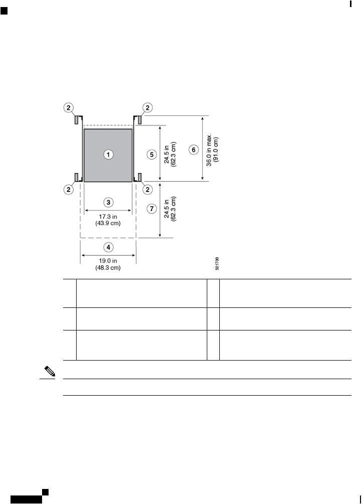
Clearance Requirements
You must provide the chassis with adequate clearance between the chassis and any other rack, device, or structure so that you can properly install the chassis, route cables, provide airflow, and maintain the switch. For the clearances required for an installation of this chassis in a four-post rack, see the following figure.
1 |
Chassis |
5 |
Depth of the chassis |
2 |
Vertical rack-mount posts and rails |
6 |
Maximum extension of the bottom-support rails |
3 |
Chassis width |
7 |
Depth of the front clearance area (this equals the |
|
|
|
depth of the chassis) |
4Widthofthefrontclearancearea(thisequalsthe width of the chassis with two rack-mount brackets attached to it)
Note Both the front and rear of the chassis must be open to both aisles for airflow.
Cisco Nexus 9336C-FX2 ACI-Mode Switch Hardware Installation Guide
10
C H A P T E R 3
Installing the Switch Chassis
•Safety, on page 11
•Installation Options with Racks and Cabinets, on page 12
•Airflow Considerations, on page 12
•Installation Guidelines, on page 12
•Unpacking and Inspecting the Switch, on page 13
•Installing the Switch, on page 14
•Grounding the Chassis, on page 18
•Starting the Switch, on page 20
Safety
Before you install, operate, or service the switch, see the Regulatory,Compliance,andSafetyInformationfor the Cisco Nexus 3000 and 9000 Series for important Safety Information.
Warning Statement 1071—Warning Definition
IMPORTANT SAFETY INSTRUCTIONS
This warning symbol means danger. You are in a situation that could cause bodily injury. Before you work on any equipment, be aware of the hazards involved with electrical circuitry and be familiar with standard practices for preventing accidents. Use the statement number provided at the end of each warning to locate its translation in the translated safety warnings that accompanied this device.
SAVE THESE INSTRUCTIONS
Warning Statement 1017—Restricted Area
This unit is intended for installation in restricted access areas. A restricted access area can be accessed only through the use of a special tool, lock and key, or other means of security.
Cisco Nexus 9336C-FX2 ACI-Mode Switch Hardware Installation Guide
11

Installing the Switch Chassis
Installation Options with Racks and Cabinets
Warning Statement 1030—Equipment Installation
Only trained and qualified personnel should be allowed to install, replace, or service this equipment.
Installation Options with Racks and Cabinets
You can install the switch in the following types of racks using the rack-mount kit shipped with the switch:
•Open EIA rack
•Perforated EIA cabinet
The rack or cabinet that you use must meet the requirements listed in General Requirements for Cabinets and Racks, on page 41.
The rack-mount kit enables you to install the switch into racks of varying depths. You can use the rack-mount kit parts to position the switch with easy access to either the port connections end of the chassis or the end of the chassis with the fan and power supply modules. For instructions on how to install the rack-mount kit, see the Installing the Switch, on page 14.
Airflow Considerations
The switch comes with fan and power supply modules that have either port-side intake or port-side exhaust airflow for cooling the switch. If you are positioning the port end of the switch in a cold aisle, make sure that the switch has port-side intake fan modules with burgundy coloring. If you are positioning the fan and power supplymodulesinacoldaisle,makesurethattheswitchhasport-sideexhaustfanmoduleswithbluecolorings. All fan modules must have the same direction of airflow.
Installation Guidelines
When installing the switch, follow these guidelines:
•Recordequipmentandinstallationinformationintheformspresentedin ChassisandModuleInformation as you install and configure the switch.
•Ensure that there is adequate clearance space around the switch to allow for servicing the switch and for adequate airflow.
•Ensure that the chassis can be adequately grounded. If the switch is not mounted in a grounded rack, we recommend connecting both the system ground on the chassis directly to an earth ground.
•Ensure that the site power meets the power requirements for the switch. If available, you can use an uninterruptible power supply (UPS) to protect against power failures.
Cisco Nexus 9336C-FX2 ACI-Mode Switch Hardware Installation Guide
12
Loading...