


 Loading...
Catalyst 2940 Switch
Hardware Installation Guide
November 2004
Corporate Headquarters
Cisco Systems, Inc. 170 West Tasman Drive
San Jose, CA 95134-1706 USA http://www.cisco.com Tel: 408 526-4000
800 553-NETS (6387) Fax: 408 526-4100
Text Part Number: OL-6157-01
THE SPECIFICATIONS AND INFORMATION REGARDING THE PRODUCTS IN THIS MANUAL ARE SUBJECT TO CHANGE WITHOUT NOTICE. ALL STATEMENTS, INFORMATION, AND RECOMMENDATIONS IN THIS MANUAL ARE BELIEVED TO BE ACCURATE BUT ARE PRESENTED WITHOUT WARRANTY OF ANY KIND, EXPRESS OR IMPLIED. USERS MUST TAKE FULL RESPONSIBILITY FOR THEIR APPLICATION OF ANY PRODUCTS.
THE SOFTWARE LICENSE AND LIMITED WARRANTY FOR THE ACCOMPANYING PRODUCT ARE SET FORTH IN THE INFORMATION PACKET THAT SHIPPED WITH THE PRODUCT AND ARE INCORPORATED HEREIN BY THIS REFERENCE. IF YOU ARE UNABLE TO LOCATE THE SOFTWARE LICENSE OR LIMITED WARRANTY, CONTACT YOUR CISCO REPRESENTATIVE FOR A COPY.
The following information is for FCC compliance of Class A devices: This equipment has been tested and found to comply with the limits for a Class A digital device, pursuant to part 15 of the FCC rules. These limits are designed to provide reasonable protection against harmful interference when the equipment is operated in a commercial environment. This equipment generates, uses, and can radiate radio-frequency energy and, if not installed and used in accordance with the instruction manual, may cause harmful interference to radio communications. Operation of this equipment in a residential area is likely to cause harmful interference, in which case users will be required to correct the interference at their own expense.
The following information is for FCC compliance of Class B devices: The equipment described in this manual generates and may radiate radio-frequency energy. If it is not installed in accordance with Cisco’s installation instructions, it may cause interference with radio and television reception. This equipment has been tested and found to comply with the limits for a Class B digital device in accordance with the specifications in part 15 of the FCC rules. These specifications are designed to provide reasonable protection against such interference in a residential installation. However, there is no guarantee that interference will not occur in a particular installation.
Modifying the equipment without Cisco’s written authorization may result in the equipment no longer complying with FCC requirements for Class A or Class B digital devices. In that event, your right to use the equipment may be limited by FCC regulations, and you may be required to correct any interference to radio or television communications at your own expense.
You can determine whether your equipment is causing interference by turning it off. If the interference stops, it was probably caused by the Cisco equipment or one of its peripheral devices. If the equipment causes interference to radio or television reception, try to correct the interference by using one or more of the following measures:
•Turn the television or radio antenna until the interference stops.
•Move the equipment to one side or the other of the television or radio.
•Move the equipment farther away from the television or radio.
•Plug the equipment into an outlet that is on a different circuit from the television or radio. (That is, make certain the equipment and the television or radio are on circuits controlled by different circuit breakers or fuses.)
Modifications to this product not authorized by Cisco Systems, Inc. could void the FCC approval and negate your authority to operate the product.
The Cisco implementation of TCP header compression is an adaptation of a program developed by the University of California, Berkeley (UCB) as part of UCB’s public domain version of the UNIX operating system. All rights reserved. Copyright © 1981, Regents of the University of California.
NOTWITHSTANDING ANY OTHER WARRANTY HEREIN, ALL DOCUMENT FILES AND SOFTWARE OF THESE SUPPLIERS ARE PROVIDED “AS IS” WITH ALL FAULTS. CISCO AND THE ABOVE-NAMED SUPPLIERS DISCLAIM ALL WARRANTIES, EXPRESSED OR IMPLIED, INCLUDING, WITHOUT LIMITATION, THOSE OF MERCHANTABILITY, FITNESS FOR A PARTICULAR PURPOSE AND NONINFRINGEMENT OR ARISING FROM A COURSE OF DEALING, USAGE, OR TRADE PRACTICE.
IN NO EVENT SHALL CISCO OR ITS SUPPLIERS BE LIABLE FOR ANY INDIRECT, SPECIAL, CONSEQUENTIAL, OR INCIDENTAL DAMAGES, INCLUDING, WITHOUT LIMITATION, LOST PROFITS OR LOSS OR DAMAGE TO DATA ARISING OUT OF THE USE OR INABILITY TO USE THIS MANUAL, EVEN IF CISCO OR ITS SUPPLIERS HAVE BEEN ADVISED OF THE POSSIBILITY OF SUCH DAMAGES.
CCSP, the Cisco Square Bridge logo, Cisco Unity, Follow Me Browsing, FormShare, and StackWise are trademarks of Cisco Systems, Inc.; Changing the Way We Work, Live, Play, and Learn, and iQuick Study are service marks of Cisco Systems, Inc.; and Aironet, ASIST, BPX, Catalyst, CCDA, CCDP, CCIE, CCIP, CCNA, CCNP, Cisco, the Cisco Certified Internetwork Expert logo, Cisco IOS, Cisco Press, Cisco Systems, Cisco Systems Capital, the Cisco Systems logo, Empowering the Internet Generation, Enterprise/Solver, EtherChannel, EtherFast, EtherSwitch, Fast Step, GigaDrive, GigaStack, HomeLink, Internet Quotient, IOS, IP/TV, iQ Expertise, the iQ logo, iQ Net Readiness Scorecard, LightStream, Linksys, MeetingPlace, MGX, the Networkers logo, Networking Academy, Network Registrar, Packet, PIX, Post-Routing, Pre-Routing, ProConnect, RateMUX, Registrar, ScriptShare, SlideCast, SMARTnet, StrataView Plus, SwitchProbe, TeleRouter, The Fastest Way to Increase Your Internet Quotient, TransPath, and VCO are registered trademarks of Cisco Systems, Inc. and/or its affiliates in the United States and certain other countries.
All other trademarks mentioned in this document or Website are the property of their respective owners. The use of the word partner does not imply a partnership relationship between Cisco and any other company. (0406R)
Catalyst 2940 Switch Hardware Installation Guide
Copyright © 2004 Cisco Systems, Inc. All rights reserved.

C O N T E N T S
|
Preface |
vii |
|
|
|
|
|
|
|
Audience |
vii |
|
|
|
|
|
|
|
Purpose |
vii |
|
|
|
|
|
|
|
Conventions vii |
|
|
|
|
|
||
|
Related Publications |
xiii |
|
|
||||
|
Obtaining Documentation |
xiv |
|
|||||
|
Cisco.com |
xiv |
|
|
|
|
||
|
Documentation CD-ROM |
xiv |
||||||
|
Ordering Documentation |
xiv |
||||||
|
Documentation Feedback |
xv |
||||||
|
Obtaining Technical Assistance |
xv |
||||||
|
Cisco TAC Website |
xv |
|
|||||
|
Opening a TAC Case |
xv |
|
|||||
|
TAC Case Priority Definitions xvi |
|||||||
|
Obtaining Additional Publications and Information xvi |
|||||||
|
Overview |
|
|
|
|
|
|
|
C H A P T E R 1 |
2-1 |
|
|
|
|
|
||
|
Setting up the Switch |
2-1 |
|
|
||||
|
Features |
2-1 |
|
|
|
|
|
|
|
Front-Panel Description |
2-2 |
|
|||||
|
Port Numbering |
2-3 |
|
|
||||
|
10/100 Ports |
2-3 |
|
|
|
|||
|
10/100/1000 Port |
2-3 |
|
|
||||
|
100BASE-FX Port |
2-4 |
|
|
||||
|
SFP Module Slot |
2-4 |
|
|
||||
|
SFP Modules |
|
2-5 |
|
|
|
||
|
Cable Guard |
2-6 |
|
|
|
|||
|
LEDs |
2-6 |
|
|
|
|
|
|
|
|
SYST LED |
2-7 |
|
|
|||
|
|
STAT, DPLX, SPD, and Port LEDs 2-7 |
||||||
Catalyst 2940 Hardware Installation Guide
|
OL-6157-01 |
iii |
|

Contents
|
Rear-Panel Description |
2-9 |
||
|
Power Connector |
2-9 |
|
|
|
Console Port |
2-10 |
|
|
|
Security Slots |
2-10 |
|
|
|
Management Options |
2-11 |
||
|
Installation 3-1 |
|
|
|
C H A P T E R 2 |
|
|
|
|
|
Preparing for Installation |
3-1 |
||
|
Warnings 3-1 |
|
|
|
|
Installation Guidelines |
3-3 |
||
|
Verifying Package Contents 3-3 |
|||
|
Verifying Switch Operation |
3-4 |
||
|
Installing the Switch |
3-5 |
|
|
|
Installing the Switch on a Desk (Without Mounting Screws) 3-5 |
|||
|
Installing the Switch on a Desk (With Mounting Screws) 3-5 |
|||
|
Installing the Switch Under a Desk |
3-7 |
||
|
Installing the Switch on a Wall |
3-9 |
|
|
|
Installing the Switch (Magnet Mount) |
3-12 |
||
|
Connecting to an SFP Module |
3-12 |
|
|
|
Connecting to 10/100 Ports and the 10/100/1000 Port 3-14 |
|||
|
Connecting to the 100BASE-FX Port |
3-15 |
|
|
|
Connecting to an SFP Module |
3-16 |
|
|
|
Where to Go Next 3-17 |
|
|
|
|
Troubleshooting 4-1 |
|
|
|
C H A P T E R 3 |
|
|
|
|
Understanding POST Results
Diagnosing Common Problems
A P P E N D I X |
A |
Technical Specifications |
A-1 |
|
|
Connectors and Cables |
|
A P P E N D I X |
B |
B-1 |
|
|
|
Connector Specifications B-1 |
|
|
|
10/100 Ports B-1 |
|
|
|
10/100/1000 Ports |
B-3 |
Connecting to 10BASE-T and 100BASE-TX Devices B-3
Connecting to 1000BASE-T Devices B-3
Catalyst 2940 Hardware Installation Guide
|
iv |
OL-6157-01 |
|
|
|

Contents
100BASE-FX Port |
B-4 |
SFP Module Slot |
B-4 |
Console Port B-5 |
|
Cable and Adapter Specifications |
B-5 |
Two Twisted-Pair Cable Pinouts |
B-5 |
Four Twisted-Pair Cable Pinouts for 10/100 Ports B-6 |
|
Four Twisted-Pair Cable Pinouts for 1000BASE-T Ports B-7 |
|
Cable and Adapter Pinouts B-8 |
|
Connecting to a PC B-8 |
|
Connecting to a Terminal |
B-8 |
Identifying a Rollover Cable |
B-9 |
A P P E N D I X C |
Configuring the Switch with the CLI-Based Setup Program D-1 |
||
|
Methods for Accessing the CLI |
D-1 |
|
|
Accessing the CLI Through Express Setup (Unconfigured Switch Only) D-1 |
||
|
Accessing the CLI Through the Console Port D-2 |
||
|
Taking Out What You Need D-2 |
|
|
|
Connecting to a Power Source |
D-3 |
|
|
Connecting to the Console Port |
D-3 |
|
|
Starting the Terminal Emulation Software |
D-4 |
|
|
Entering the Initial Configuration Information |
D-5 |
|
|
IP Settings D-5 |
|
|
|
Completing the Setup Program |
D-6 |
|
|
Where to Go Next D-8 |
|
|
I N D E X
Catalyst 2940 Hardware Installation Guide
|
OL-6157-01 |
v |
|

Contents
Catalyst 2940 Hardware Installation Guide
|
vi |
OL-6157-01 |
|
|
|

Preface
Audience
This guide is for the networking or computer technician responsible for installing a Catalyst 2940 switch, hereafter referred to as the switch. We assume that you are familiar with the concepts and terminology of Ethernet and local area networking.
Purpose
This guide describes the hardware features of Catalyst 2940 switch. It describes the physical and performance characteristics of the switch, explains how to install a switch, and provides troubleshooting information.
This guide does not describe how to configure software features on your switch or describe the Catalyst 2940-specific system messages that you might encounter. It also does not provide information about command-line interface (CLI) commands that have been created or changed for use by the switch. For more information, see the switch software configuration guide, the switch system message guide, and the switch command reference.
Conventions
Notes, cautions, and warnings use these conventions and symbols:
Note Means reader take note. Notes contain helpful suggestions or references to materials not contained in this manual.
Caution Means reader be careful. In this situation, you might do something that could result in equipment damage or loss of data.
Catalyst 2940 Switch Hardware Installation Guide
|
OL-6157-01 |
vii |
|

Preface
Conventions
Warning IMPORTANT SAFETY INSTRUCTIONS
This warning symbol means danger. You are in a situation that could cause bodily injury. Before you work on any equipment, be aware of the hazards involved with electrical circuitry and be familiar with standard practices for preventing accidents. Use the statement number provided at the end of each warning to locate its translation in the translated safety warnings that accompanied this device. Statement 1071
SAVE THESE INSTRUCTIONS
Waarschuwing BELANGRIJKE VEILIGHEIDSINSTRUCTIES
Dit waarschuwingssymbool betekent gevaar. U verkeert in een situatie die lichamelijk letsel kan veroorzaken. Voordat u aan enige apparatuur gaat werken, dient u zich bewust te zijn van de bij elektrische schakelingen betrokken risico's en dient u op de hoogte te zijn van de standaard praktijken om ongelukken te voorkomen. Gebruik het nummer van de verklaring onderaan de waarschuwing als u een vertaling van de waarschuwing die bij het apparaat wordt geleverd, wilt raadplegen.
BEWAAR DEZE INSTRUCTIES
Varoitus TÄRKEITÄ TURVALLISUUSOHJEITA
Tämä varoitusmerkki merkitsee vaaraa. Tilanne voi aiheuttaa ruumiillisia vammoja. Ennen kuin käsittelet laitteistoa, huomioi sähköpiirien käsittelemiseen liittyvät riskit ja tutustu onnettomuuksien yleisiin ehkäisytapoihin. Turvallisuusvaroitusten käännökset löytyvät laitteen mukana toimitettujen käännettyjen turvallisuusvaroitusten joukosta varoitusten lopussa näkyvien lausuntonumeroiden avulla.
SÄILYTÄ NÄMÄ OHJEET
Attention IMPORTANTES INFORMATIONS DE SÉCURITÉ
Ce symbole d'avertissement indique un danger. Vous vous trouvez dans une situation pouvant entraîner des blessures ou des dommages corporels. Avant de travailler sur un équipement, soyez conscient des dangers liés aux circuits électriques et familiarisez-vous avec les procédures couramment utilisées pour éviter les accidents. Pour prendre connaissance des traductions des avertissements figurant dans les consignes de sécurité traduites qui accompagnent cet appareil, référez-vous au numéro de l'instruction situé à la fin de chaque avertissement.
CONSERVEZ CES INFORMATIONS
Warnung WICHTIGE SICHERHEITSHINWEISE
Dieses Warnsymbol bedeutet Gefahr. Sie befinden sich in einer Situation, die zu Verletzungen führen kann. Machen Sie sich vor der Arbeit mit Geräten mit den Gefahren elektrischer Schaltungen und den üblichen Verfahren zur Vorbeugung vor Unfällen vertraut. Suchen Sie mit der am Ende jeder Warnung angegebenen Anweisungsnummer nach der jeweiligen Übersetzung in den übersetzten Sicherheitshinweisen, die zusammen mit diesem Gerät ausgeliefert wurden.
BEWAHREN SIE DIESE HINWEISE GUT AUF.
Catalyst 2940 Switch Hardware Installation Guide
|
viii |
OL-6157-01 |
|
|
|

Preface
Conventions
Avvertenza IMPORTANTI ISTRUZIONI SULLA SICUREZZA
Questo simbolo di avvertenza indica un pericolo. La situazione potrebbe causare infortuni alle persone. Prima di intervenire su qualsiasi apparecchiatura, occorre essere al corrente dei pericoli relativi ai circuiti elettrici e conoscere le procedure standard per la prevenzione di incidenti. Utilizzare il numero di istruzione presente alla fine di ciascuna avvertenza per individuare le traduzioni delle avvertenze riportate in questo documento.
CONSERVARE QUESTE ISTRUZIONI
Advarsel VIKTIGE SIKKERHETSINSTRUKSJONER
Dette advarselssymbolet betyr fare. Du er i en situasjon som kan føre til skade på person. Før du begynner å arbeide med noe av utstyret, må du være oppmerksom på farene forbundet med elektriske kretser, og kjenne til standardprosedyrer for å forhindre ulykker. Bruk nummeret i slutten av hver advarsel for å finne oversettelsen i de oversatte sikkerhetsadvarslene som fulgte med denne enheten.
TA VARE PÅ DISSE INSTRUKSJONENE
Aviso INSTRUÇÕES IMPORTANTES DE SEGURANÇA
Este símbolo de aviso significa perigo. Você está em uma situação que poderá ser causadora de lesões corporais. Antes de iniciar a utilização de qualquer equipamento, tenha conhecimento dos perigos envolvidos no manuseio de circuitos elétricos e familiarize-se com as práticas habituais de prevenção de acidentes. Utilize o número da instrução fornecido ao final de cada aviso para localizar sua tradução nos avisos de segurança traduzidos que acompanham este dispositivo.
GUARDE ESTAS INSTRUÇÕES
¡Advertencia! INSTRUCCIONES IMPORTANTES DE SEGURIDAD
Este símbolo de aviso indica peligro. Existe riesgo para su integridad física. Antes de manipular cualquier equipo, considere los riesgos de la corriente eléctrica y familiarícese con los procedimientos estándar de prevención de accidentes. Al final de cada advertencia encontrará el número que le ayudará a encontrar el texto traducido en el apartado de traducciones que acompaña a este dispositivo.
GUARDE ESTAS INSTRUCCIONES
Varning! VIKTIGA SÄKERHETSANVISNINGAR
Denna varningssignal signalerar fara. Du befinner dig i en situation som kan leda till personskada. Innan du utför arbete på någon utrustning måste du vara medveten om farorna med elkretsar och känna till vanliga förfaranden för att förebygga olyckor. Använd det nummer som finns i slutet av varje varning för att hitta dess översättning i de översatta säkerhetsvarningar som medföljer denna anordning.
SPARA DESSA ANVISNINGAR
Catalyst 2940 Switch Hardware Installation Guide
|
OL-6157-01 |
ix |
|
Preface
Conventions
Catalyst 2940 Switch Hardware Installation Guide
|
x |
OL-6157-01 |
|
|
|
Preface
Conventions
Aviso INSTRUÇÕES IMPORTANTES DE SEGURANÇA
Este símbolo de aviso significa perigo. Você se encontra em uma situação em que há risco de lesões corporais. Antes de trabalhar com qualquer equipamento, esteja ciente dos riscos que envolvem os circuitos elétricos e familiarize-se com as práticas padrão de prevenção de acidentes. Use o número da declaração fornecido ao final de cada aviso para localizar sua tradução nos avisos de segurança traduzidos que acompanham o dispositivo.
GUARDE ESTAS INSTRUÇÕES
Advarsel VIGTIGE SIKKERHEDSANVISNINGER
Dette advarselssymbol betyder fare. Du befinder dig i en situation med risiko for legemesbeskadigelse. Før du begynder arbejde på udstyr, skal du være opmærksom på de involverede risici, der er ved elektriske kredsløb, og du skal sætte dig ind i standardprocedurer til undgåelse af ulykker. Brug erklæringsnummeret efter hver advarsel for at finde oversættelsen i de oversatte advarsler, der fulgte med denne enhed.
GEM DISSE ANVISNINGER
Catalyst 2940 Switch Hardware Installation Guide
|
OL-6157-01 |
xi |
|

Preface
Conventions
Catalyst 2940 Switch Hardware Installation Guide
|
xii |
OL-6157-01 |
|
|
|

Preface
Related Publications
Related Publications
These documents provide complete information about the switch and are available from this URL:
http://www.cisco.com/univercd/cc/td/doc/product/lan/cat2940/index.htm
You can order printed copies of documents with a DOC-xxxxxx= number from the Cisco.com sites and from the telephone numbers listed in the “Ordering Documentation” section on page xiv.
• Release Notes for the Catalyst 2940 Switch (not orderable but available on Cisco.com)
Note Switch requirements and procedures for initial configurations and software upgrades tend to change and therefore appear only in the release notes. Before installing, configuring, or upgrading the switch, see the release notes on Cisco.com for the latest information.
For hardware information about the switch, see these documents:
•Catalyst 2940 Switch Hardware Installation Guide (not orderable but available on Cisco.com)
•Catalyst 2940 Switch Getting Started Guide (order number DOC-7816576=)
•Regulatory Compliance and Safety Information for the Catalyst 2940 Switch
(order number DOC-7816656=)
For software information for the Catalyst 2940 switches, see these documents:
•Catalyst 2940 Switch Software Configuration Guide (order number DOC-7815507=)
•Catalyst 2940 Switch Command Reference (order number DOC-785505=)
•Catalyst 2940 Switch System Message Guide (order number DOC-7815504=)
•Release Notes for the Catalyst 2940 Switch (not orderable but is available on Cisco.com)
•Installation Notes for the Catalyst 2940 Switch Cable Guard (order number DOC-7815689=)
•Device manager online help (available on the switch)
•Getting Started with Cisco Network Assistant (not orderable but available on Cisco.com) For information about small form-factor (SFP) modules, see these documents:
•Cisco Small Form-Factor Pluggable Modules Installation Notes (order number DOC-7815160=)
•Compatibility Matrix for the Small Form-Factor Pluggable Modules (not orderable but is available on Cisco.com)
Catalyst 2940 Switch Hardware Installation Guide
|
OL-6157-01 |
xiii |
|

Preface
Obtaining Documentation
Obtaining Documentation
Cisco provides several ways to obtain documentation, technical assistance, and other technical resources. These sections explain how to obtain technical information from Cisco Systems.
Cisco.com
You can access the most current Cisco documentation on the World Wide Web at this URL:
http://www.cisco.com/univercd/home/home.htm
You can access the Cisco website at this URL:
http://www.cisco.com
International Cisco websites can be accessed from this URL:
http://www.cisco.com/public/countries_languages.shtml
Documentation CD-ROM
Cisco documentation and additional literature are available in a Cisco Documentation CD-ROM package, which may have shipped with your product. The Documentation CD-ROM is updated regularly and may be more current than printed documentation. The CD-ROM package is available as a single unit or through an annual or quarterly subscription.
Registered Cisco.com users can order a single Documentation CD-ROM (product number
DOC-CONDOCCD=) through the Cisco Ordering tool:
http://www.cisco.com/en/US/partner/ordering/ordering_place_order_ordering_tool_launch.html
All users can order annual or quarterly subscriptions through the online Subscription Store:
http://www.cisco.com/go/subscription
Ordering Documentation
You can find instructions for ordering documentation at this URL:
http://www.cisco.com/univercd/cc/td/doc/es_inpck/pdi.htm
You can order Cisco documentation in these ways:
•Registered Cisco.com users (Cisco direct customers) can order Cisco product documentation from the Networking Products MarketPlace:
http://www.cisco.com/en/US/partner/ordering/index.shtml
•Nonregistered Cisco.com users can order documentation through a local account representative by calling Cisco Systems Corporate Headquarters (California, USA.) at 408 526-7208 or, elsewhere in North America, by calling 800 553-NETS (6387).
Catalyst 2940 Switch Hardware Installation Guide
|
xiv |
OL-6157-01 |
|
|
|

Preface
Obtaining Technical Assistance
Documentation Feedback
You can submit comments electronically on Cisco.com. On the Cisco Documentation home page, click Feedback at the top of the page.
You can send your comments in e-mail to bug-doc@cisco.com.
You can submit comments by using the response card (if present) behind the front cover of your document or by writing to the following address:
Cisco Systems
Attn: Customer Document Ordering
170 West Tasman Drive
San Jose, CA 95134-9883
We appreciate your comments.
Obtaining Technical Assistance
For all customers, partners, resellers, and distributors who hold valid Cisco service contracts, the Cisco Technical Assistance Center (TAC) provides 24-hour, award-winning technical support services, online and over the phone. Cisco.com features the Cisco TAC website as an online starting point for technical assistance.
Cisco TAC Website
The Cisco TAC website (http://www.cisco.com/tac) provides online documents and tools for troubleshooting and resolving technical issues with Cisco products and technologies. The Cisco TAC website is available 24 hours a day, 365 days a year.
Accessing all the tools on the Cisco TAC website requires a Cisco.com user ID and password. If you have a valid service contract but do not have a login ID or password, register at this URL:
http://tools.cisco.com/RPF/register/register.do
Opening a TAC Case
The online TAC Case Open Tool (http://www.cisco.com/tac/caseopen) is the fastest way to open P3 and P4 cases. (Your network is minimally impaired or you require product information). After you describe your situation, the TAC Case Open Tool automatically recommends resources for an immediate solution. If your issue is not resolved using these recommendations, your case will be assigned to a Cisco TAC engineer.
For P1 or P2 cases (your production network is down or severely degraded) or if you do not have Internet access, contact Cisco TAC by telephone. Cisco TAC engineers are assigned immediately to P1 and P2 cases to help keep your business operations running smoothly.
Catalyst 2940 Switch Hardware Installation Guide
|
OL-6157-01 |
xv |
|

Preface
Obtaining Additional Publications and Information
To open a case by telephone, use one of the following numbers:
Asia-Pacific: +61 2 8446 7411 (Australia: 1 800 805 227)
EMEA: +32 2 704 55 55
USA: 1 800 553-2447
For a complete listing of Cisco TAC contacts, go to this URL:
http://www.cisco.com/warp/public/687/Directory/DirTAC.shtml
TAC Case Priority Definitions
To ensure that all cases are reported in a standard format, Cisco has established case priority definitions.
Priority 1 (P1)—Your network is “down” or there is a critical impact to your business operations. You and Cisco will commit all necessary resources around the clock to resolve the situation.
Priority 2 (P2)—Operation of an existing network is severely degraded, or significant aspects of your business operation are negatively affected by inadequate performance of Cisco products. You and Cisco will commit full-time resources during normal business hours to resolve the situation.
Priority 3 (P3)—Operational performance of your network is impaired, but most business operations remain functional. You and Cisco will commit resources during normal business hours to restore service to satisfactory levels.
Priority 4 (P4)—You require information or assistance with Cisco product capabilities, installation, or configuration. There is little or no effect on your business operations.
Obtaining Additional Publications and Information
Information about Cisco products, technologies, and network solutions is available from various online and printed sources.
•The Cisco Product Catalog describes the networking products offered by Cisco Systems, as well as ordering and customer support services. Access the Cisco Product Catalog at this URL:
http://www.cisco.com/en/US/products/products_catalog_links_launch.html
•Cisco Press publishes a wide range of networking publications. Cisco suggests these titles for new and experienced users: Internetworking Terms and Acronyms Dictionary, Internetworking Technology Handbook, Internetworking Troubleshooting Guide, and the Internetworking Design Guide. For current Cisco Press titles and other information, go to Cisco Press online at this URL:
http://www.ciscopress.com
•Packet magazine is the Cisco quarterly publication that provides the latest networking trends, technology breakthroughs, and Cisco products and solutions to help industry professionals get the most from their networking investment. Included are networking deployment and troubleshooting tips, configuration examples, customer case studies, tutorials and training, certification information, and links to numerous in-depth online resources. You can access Packet magazine at this URL:
http://www.cisco.com/go/packet
•iQ Magazine is the Cisco bimonthly publication that delivers the latest information about Internet business strategies for executives. You can access iQ Magazine at this URL:
http://www.cisco.com/go/iqmagazine
Catalyst 2940 Switch Hardware Installation Guide
|
xvi |
OL-6157-01 |
|
|
|

Preface
Obtaining Additional Publications and Information
•Internet Protocol Journal is a quarterly journal published by Cisco Systems for engineering professionals involved in designing, developing, and operating public and private internets and intranets. You can access the Internet Protocol Journal at this URL:
http://www.cisco.com/en/US/about/ac123/ac147/about_cisco_the_internet_protocol_journal.html
•Training—Cisco offers world-class networking training. Current offerings in network training are listed at this URL:
http://www.cisco.com/en/US/learning/index.html
Catalyst 2940 Switch Hardware Installation Guide
|
OL-6157-01 |
xvii |
|

Preface
Obtaining Additional Publications and Information
Catalyst 2940 Switch Hardware Installation Guide
|
xviii |
OL-6157-01 |
|
|
|

C H A P T E R 1
Overview
This chapter provides information about these topics:
•Setting up the Switch, page 1-1
•Features, page 1-1
•Front-Panel Description, page 1-2
•Rear-Panel Description, page 1-9
•Management Options, page 1-11
Setting up the Switch
See the Catalyst 2940 Switch Getting Started Guide for instructions on initially configuring your Catalyst switch by using the Express Setup. Also covered in the getting started guide are switch management options, basic rack-mounting procedures, port and module connections, power connection procedures, and troubleshooting help. For instructions on setting up your switch by using the command-line interface (CLI), see Appendix C, “Configuring the Switch with the CLI-Based
Setup Program.”
Features
The Catalyst 2940 switches are a family of Ethernet switches that you can use to connect workstations and other network devices, such as servers, routers, and other switches. All models of the switch are cluster-capable.
See the switch software configuration guide for examples that show how you might deploy the switches in your network.
These are the switch features:
•Hardware
–Catalyst 2940-8TT-S switch—Eight 10/100 Ethernet ports and one Gigabit Ethernet 10/100/1000 port.
–Catalyst 2940-8TF-S switch—Eight 10/100 Ethernet ports, one 100BASE-FX port, and one small-form-factor pluggable (SFP) module slot. The Cisco SFP modules that are supported by this switch include the1000BASE-LX, 1000BASE-SX, Coarse Wavelength Division Multiplexing (CDWM) fiber-optic modules, and the 1000BASE-T copper module.
Catalyst 2940 Switch Hardware Installation Guide
|
OL-6157-01 |
1-1 |
|
|
|
Chapter 1 Overview
Front-Panel Description
•Configuration
–Supports manual and autoconfiguration for 10/100 ports
–Supports manual configuration at 10 or 100 Mbps for 10/100/1000 port (full duplex only at 1000 Mbps)
–Supports only 100 Mbps and full duplex for 100BASE-FX port
–Supports 8192 MAC addresses
–Checks for errors on a received packet, determines the destination port, stores the packet in shared memory, and then forwards the packet to the destination port
Front-Panel Description
The switch front panel contains the ports, the LEDs, and the Mode button.
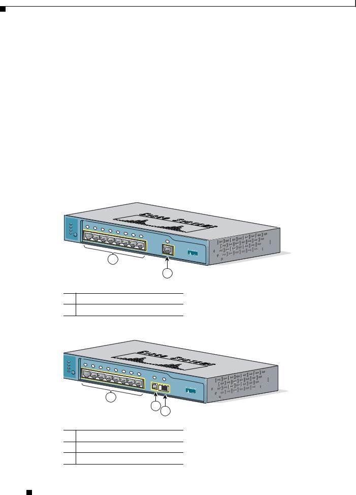
Figure 1-1 and Figure 1-2 show the switches.
Figure 1-1 Catalyst 2940-8TT-S Switch
SYST |
|
|
|
|
|
|
|
|
|
|
|
STAT |
|
1x |
2x |
|
|
|
|
|
|
|
|
DPLX |
|
|
3x |
|
|
|
|
|
|
|
|
|
|
|
4x |
|
|
|
|
|
|
||
SPD |
|
|
|
|
5x |
|
|
|
|
|
|
|
|
|
|
|
6x |
7x |
|
|
|
||
|
|
|
|
|
|
|
|
|
|
||
|
|
|
|
|
|
|
|
8x |
|
|
|
|
MODE |
|
|
|
|
|
|
|
Catalyst |
|
|
|
|
|
|
|
|
|
|
|
|
||
|
|
|
|
|
|
|
|
|
|
|
|
|
|
|
|
|
|
|
|
|
1 |
2940 |
SERIES |
|
|
|
|
|
|
|
|
|
|
1
2
1 10/100 Ethernet ports
2 10/100/1000 Gigabit Ethernet port
Figure 1-2 Catalyst 2940-8TF-S Switch
89451
SERIES
2
3
110/100 Ethernet ports
2100BASE-FX port
3SFP module slot
89452
Catalyst 2940 Switch Hardware Installation Guide
1-2 |
OL-6157-01 |
|
|
Chapter 1 Overview
Front-Panel Description
Port Numbering
Table 1-1 lists the port and slot numbering for the Catalyst 2940 switches.
Table 1-1 Port and Slot Numbering
Port or Slot type |
Catalyst 2940-8TT-S |
Catalyst 2940-8TF-S |
|
|
|
10/100 Ethernet |
1 through 8 |
1 through 8 |
|
|
|
Gigabit Ethernet |
1 |
— |
10/100/1000 |
|
|
|
|
|
100BASE-FX |
— |
9 |
|
|
|
SFP module |
— |
1 |
|
|
|
10/100 Ports
The 10/100 ports use RJ-45 connectors and twisted-pair cabling. The ports can connect to these devices:
•10BASE-T devices, such as workstations and hubs, through standard RJ-45 connectors and two twisted-pair cabling. You can use Category 3, 4, or 5 cabling.
•100BASE-TX devices, such as high-speed workstations, servers, hubs, routers, and other switches, through standard RJ-45 connectors and two or four twisted-pair, Category 5 cabling.
Note When connecting the switch to workstations, servers, and routers, be sure that the cable is a twisted-pair straight-through cable. When connecting the switch to hubs or other switches, use a twisted-pair crossover cable. Pinouts for the cables are described in Appendix B, “Connectors and Cables.”
The 10/100 ports can be explicitly set to operate in any combination of half duplex, full duplex, 10 Mbps, or 100 Mbps. They can also be set for speed and duplex autonegotiation, compliant with IEEE 802.3U. In all cases, the cable length from a switch to an attached device cannot exceed 328 feet (100 meters).
When set for autonegotiation, a port senses the speed and duplex settings of the attached device and advertises its own capabilities. If the attached device supports autonegotiation, the port negotiates the best connection (that is, the fastest line speed that both devices support and full-duplex transmission, if the attached device supports it) and configures itself accordingly.
10/100/1000 Port
The 10/100/1000 port on the Catalyst 2940-8TT-S switch uses RJ-45 connectors and twisted-pair cabling. The port can connect to these devices:
•10BASE-T devices, such as workstations and hubs, through standard RJ-45 connectors and two or four twisted-pair, Category 5 cabling.
•100BASE-TX devices, such as high-speed workstations, servers, hubs, routers, and other switches, through standard RJ-45 connectors and two or four twisted-pair, Category 5 cabling.
•1000BASE-T devices, such as high-speed workstations, servers, hubs, routers, and other switches, through standard RJ-45 connectors and four twisted-pair, Category 5 cabling.
Catalyst 2940 Switch Hardware Installation Guide
|
OL-6157-01 |
1-3 |
|
|
|

Chapter 1 Overview
Front-Panel Description
Note When connecting the switch to a 1000BASE-T device, be sure to use a four twisted-pair, Category 5 cable.
Note When connecting the switch to workstations, servers, and routers, be sure to use a twisted-pair straight-through cable. When connecting the switch to hubs or other switches, use a twisted-pair crossover cable. Pinouts for the cables are described in Appendix B, “Connectors and Cables.”
The 10/100/1000 port on the Catalyst 2940-8TT-S switch can be explicitly set to operate at fullor half-duplex at 10 or 100 Mbps. The port is restricted to full-duplex mode when it is set at 1000 Mbps.
The port can also be set for speed autonegotiation, compliant with IEEE 802.3AB. In all cases, the cable length from a switch to an attached device cannot exceed 328 feet (100 meters).
100BASE-FX Port
The 100BASE-FX port on the Catalyst 2940-8TF-S switch can use either 50/125or 62.5/125-micron multimode fiber-optic cabling. The 100BASE-FX port operates only at 100 Mbps in full-duplex mode.
In full-duplex mode, the cable length from the 100BASE-FX port to an attached device cannot exceed 6562 feet (2 kilometers).
You can use only the 100BASE-FX port or the SFP module slot at one time. When the switch is first powered on, the 100BASE-FX port is enabled by default. However, if an SFP module is already installed in the switch, the SFP module slot is enabled.
You can connect the 100BASE-FX port to an SC port on a target device by using one of the MT-RJ fiber-optic patch cables listed in Table 1-2. Use the Cisco part numbers in Table 1-2 to order the patch cables that you need.
Table 1-2 MT-RJ Patch Cables for 100BASE-FX Connections
Type |
Cisco Part Number |
|
|
1-meter, MT-RJ-to-SC multimode cable |
CAB-MTRJ-SC-MM-1M= |
|
|
3-meter, MT-RJ-to-SC multimode cable |
CAB-MTRJ-SC-MM-3M= |
|
|
5-meter, MT-RJ-to-SC multimode cable |
CAB-MTRJ-SC-MM-5M= |
|
|
SFP Module Slot
The SFP module slot supports copper or fiber-optic SFP modules. The SFP module slot is numbered as port 1.
Note You can use only the SFP module slot or the 100BASE-FX port at one time. When the switch is first powered on, the 100BASE-FX port is enabled by default. However, if an SFP module is already installed in the switch, the SFP module slot is enabled.
If you install an SFP module after the switch has powered on, you must reload the switch to enable the SFP module.
Catalyst 2940 Switch Hardware Installation Guide
1-4 |
OL-6157-01 |
|
|

Chapter 1 Overview
Front-Panel Description
SFP Modules
The Catalyst 2940-8TF-S switch uses a field-replaceable SFP module to establish Gigabit connections. You insert an SFP module into the SFP module slot on the front of the switch.
The Cisco SFP modules that are supported by the Catalyst 2940-8TF-S switch include:
•1000BASE-LX, fiber-optic
•1000BASE-SX, fiber-optic
•1000BASE-T, copper
•Coarse Wavelength-Division Multiplexing (CDWM), fiber-optic
Note The Catalyst 2940-8TF-S switch only supports 1000 Mbps and full-duplex modes on SFP modules.
The 1000BASE-LX and 1000BASE-SX SFP modules are used to establish fiber-optic connections. You use fiber-optic cables with LC connectors to connect to an SFP module. The SFP modules support 850 to 1550 nm nominal wavelengths. These field-replaceable modules provide the uplink optical interfaces, laser send (TX), and laser receive (RX).
The restrictions are that each port must match the wave-length specifications on the other end of the cable, and the cable must not exceed the stipulated cable length for reliable communications. Table 1-3 lists these stipulations.
Table 1-3 Cabling Stipulations for Fiber-Optic SFP Modules
|
|
|
|
|
|
8 micron |
|
62.5/125 micron |
50/125 micron |
62.5/125 micron |
50/125 micron |
9/125 micron |
Single-mode |
SFP |
Multimode |
Multimode |
Multimode |
Multimode |
Single-mode |
Dispersion |
Module |
850 nm1 Fiber |
850 nm Fiber |
1310 nm Fiber |
1310 nm Fiber |
1310 nm Fiber |
Shifted Fiber |
SX |
275 m2 at |
550 m at |
|
|
|
— |
|
200 Mhz-km |
500 Mhz-km |
|
|
|
|
|
|
|
|
|
|
|
LX |
— |
— |
550 m at |
550 m at |
10 km |
— |
|
|
|
500 Mhz-km |
400 Mhz-km |
|
|
|
|
|
|
|
|
|
CWDM3 |
1470, 1490, 1510, |
SMF |
9/125 |
— |
62 miles (100 |
1470, 1490, |
|
1530, 1550, 1570, |
|
|
|
km) |
1510, 1530, |
|
1590, 1610 |
|
|
|
|
1550, 1570, |
|
|
|
|
|
|
1590, 1610 |
|
|
|
|
|
|
|
1.nm = nanometer
2.m = meter
3.CWDM = Coarse Wavelength-Division Multiplexing
The 1000BASE-T SFP module is used to establish a Gigabit Ethernet connection through a Category 5 (copper) cable. This module can provide a Gigabit Ethernet connection of up to 100 meters through a Category 5 cable.
Use only Cisco SFP modules on the Catalyst 2940-8TF-S switch. Each SFP module has an internal serial EEPROM that is encoded with security information. This encoding provides a way for Cisco to identify and validate that the SFP module meets the requirements for the switch.
Catalyst 2940 Switch Hardware Installation Guide
|
OL-6157-01 |
1-5 |
|
|
|
Chapter 1 Overview
Front-Panel Description
The Cisco CWDM SFPs operate on single-mode fiber. The SFPs support both Gigabit Ethernet as well as fiber channel (1 Gigabit and 2 Gigabit) links. For more information about Cisco CWDM SFPs, see the Cisco CWDM SFP Compatibility Matrix at this URL: http://www.cisco.com/issg/tmg/cwdm.shtml#matrix
Also see your SFP module documentation and the Cisco Small Form-Factor Pluggable Modules Installation Notes (not orderable but is available on Cisco.com).
For the latest information about SFP modules supported by the switch, see the release notes.
Cable Guard
You can order an optional cable guard to secure cables to the front of the switch and prevent them from being accidentally removed. To order a cable guard, contact your Cisco representative.
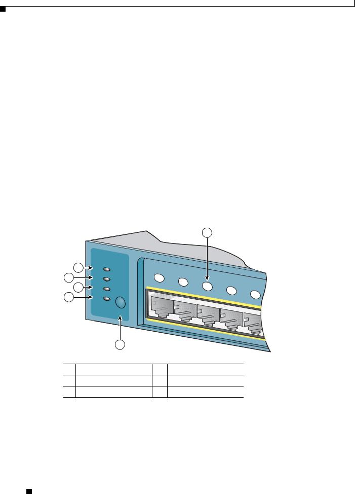
LEDs
There are four LEDs on the left panel of the switch, and there are port status LEDs above all the switch ports, as shown in Figure 1-3.
Figure 1-3 LEDs on Catalyst 2940 Switches
1
|
3 |
SYST |
|
|
|
|
|
|
4 |
|
STAT |
|
1x |
2x |
|
|
|
|
5 |
DPLX |
|
|
3x |
|
|
|
|
|
|
|
4x |
|
|||
|
|
|
|
|
5x |
|||
6 |
|
SPD |
|
|
|
|
||
|
|
|
|
|
|
|||
|
|
|
|
|
|
|
||
|
|
MODE |
|
|
|
|
|
|
|
|
2 |
|
|
|
|
|
|
1 |
Port status LED |
4 |
|
STAT LED |
|
|
|
|
2 |
Mode button |
5 |
|
DPLX LED |
|
|
|
|
3 |
SYST LED |
6 |
|
SPD LED |
|
|
|
|
You can use these LEDs to monitor switch activity and performance:
89453
•The system (SYST) continually displays the system status. The SYST LED color shows the switch status.
•The status (STAT), duplex (DPLX), and speed (SPD) LEDs show the information that is being displayed by the port status LEDs. Pressing the Mode button cycles the LEDs through the STAT, DPLX, and SPD displays.
Catalyst 2940 Switch Hardware Installation Guide
1-6 |
OL-6157-01 |
|
|

Chapter 1 Overview
Front-Panel Description
All of the LEDs described in this section are visible through the GUI management applications—the Network Assistant application for multiple switches and the device manager for a single switch. The switch software configuration guide describes how to use the CLI to configure and to monitor individual switches and switch clusters.
SYST LED
The SYST LED shows whether the system is receiving power and functioning properly. Table 1-4 lists the LED colors and meanings.
Table 1-4 System LED
Color |
System Status |
|
|
Off |
System is not powered on. |
|
|
Green |
System is operating normally. |
|
|
Amber |
System is receiving power but is not functioning properly. |
|
|
For information about the system LED colors during the power-on self-test (POST), see the “Understanding POST Results” section on page 3-1.
STAT, DPLX, SPD, and Port LEDs
Press the Mode button to cycle through the STAT, DPLX, and SPD LED displays. When the LED is highlighted for the mode that you want, release the button to enable that highlighted mode.
Table 1-5 lists the mode meanings.
Table 1-5 Port Mode LEDs
Mode LED |
Port Mode |
Description |
|
|
|
STAT |
Port status |
Port status. This is the default mode. |
|
|
|
DPLX |
Port duplex mode |
Port duplex mode: half duplex or full duplex. |
|
|
|
SPD |
Port speed |
Port operating speed: 10 or 100 Mbps for 10/100 ports and |
|
|
10, 100, or 1000 Mbps for 10/100/1000 ports. |
|
|
|
Each port has a port status LED, also called a port LED. These LEDs display information about the individual ports. When you change the port mode, the meanings of the port LED colors change. Table 1-6 explains how to interpret these colors.
Catalyst 2940 Switch Hardware Installation Guide
|
OL-6157-01 |
1-7 |
|
|
|
Loading...