


 Loading...
Cisco IE 3000 Switch Hardware
Installation Guide
First Published: March 2013
Last Updated: December 23, 2014
Cisco Systems, Inc.
www.cisco.com
Cisco has more than 200 offices worldwide. Addresses, phone numbers, and fax numbers are listed on the Cisco website at www.cisco.com/go/offices.
THE SPECIFICATIONS AND INFORMATION REGARDING THE PRODUCTS IN THIS MANUAL ARE SUBJECT TO CHANGE WITHOUT NOTICE. ALL STATEMENTS, INFORMATION, AND RECOMMENDATIONS IN THIS MANUAL ARE BELIEVED TO BE ACCURATE BUT ARE PRESENTED WITHOUT WARRANTY OF ANY KIND, EXPRESS OR IMPLIED. USERS MUST TAKE FULL RESPONSIBILITY FOR THEIR APPLICATION OF ANY PRODUCTS.
THE SOFTWARE LICENSE AND LIMITED WARRANTY FOR THE ACCOMPANYING PRODUCT ARE SET FORTH IN THE INFORMATION PACKET THAT SHIPPED WITH THE PRODUCT AND ARE INCORPORATED HEREIN BY THIS REFERENCE. IF YOU ARE UNABLE TO LOCATE THE SOFTWARE LICENSE OR LIMITED WARRANTY, CONTACT YOUR CISCO REPRESENTATIVE FOR A COPY.
The following information is for FCC compliance of Class A devices: This equipment has been tested and found to comply with the limits for a Class A digital device, pursuant to part 15 of the FCC rules. These limits are designed to provide reasonable protection against harmful interference when the equipment is operated in a commercial environment. This equipment generates, uses, and can radiate radio-frequency energy and, if not installed and used in accordance with the instruction manual, may cause harmful interference to radio communications. Operation of this equipment in a residential area is likely to cause harmful interference, in which case users will be required to correct the interference at their own expense.
The following information is for FCC compliance of Class B devices: The equipment described in this manual generates and may radiate radio-frequency energy. If it is not installed in accordance with Cisco’s installation instructions, it may cause interference with radio and television reception. This equipment has been tested and found to comply with the limits for a Class B digital device in accordance with the specifications in part 15 of the FCC rules. These specifications are designed to provide reasonable protection against such interference in a residential installation. However, there is no guarantee that interference will not occur in a particular installation.
Modifying the equipment without Cisco’s written authorization may result in the equipment no longer complying with FCC requirements for Class A or Class B digital devices. In that event, your right to use the equipment may be limited by FCC regulations, and you may be required to correct any interference to radio or television communications at your own expense.
You can determine whether your equipment is causing interference by turning it off. If the interference stops, it was probably caused by the Cisco equipment or one of its peripheral devices. If the equipment causes interference to radio or television reception, try to correct the interference by using one or more of the following measures:
•Turn the television or radio antenna until the interference stops.
•Move the equipment to one side or the other of the television or radio.
•Move the equipment farther away from the television or radio.
•Plug the equipment into an outlet that is on a different circuit from the television or radio. (That is, make certain the equipment and the television or radio are on circuits controlled by different circuit breakers or fuses.)
Modifications to this product not authorized by Cisco Systems, Inc. could void the FCC approval and negate your authority to operate the product.
The Cisco implementation of TCP header compression is an adaptation of a program developed by the University of California, Berkeley (UCB) as part of UCB’s public domain version of the UNIX operating system. All rights reserved. Copyright © 1981, Regents of the University of California.
NOTWITHSTANDING ANY OTHER WARRANTY HEREIN, ALL DOCUMENT FILES AND SOFTWARE OF THESE SUPPLIERS ARE PROVIDED “AS IS” WITH ALL FAULTS. CISCO AND THE ABOVE-NAMED SUPPLIERS DISCLAIM ALL WARRANTIES, EXPRESSED OR IMPLIED, INCLUDING, WITHOUT LIMITATION, THOSE OF MERCHANTABILITY, FITNESS FOR A PARTICULAR PURPOSE AND NONINFRINGEMENT OR ARISING FROM A COURSE OF DEALING, USAGE, OR TRADE PRACTICE.
IN NO EVENT SHALL CISCO OR ITS SUPPLIERS BE LIABLE FOR ANY INDIRECT, SPECIAL, CONSEQUENTIAL, OR INCIDENTAL DAMAGES, INCLUDING, WITHOUT LIMITATION, LOST PROFITS OR LOSS OR DAMAGE TO DATA ARISING OUT OF THE USE OR INABILITY TO USE THIS MANUAL, EVEN IF CISCO OR ITS SUPPLIERS HAVE BEEN ADVISED OF THE POSSIBILITY OF SUCH DAMAGES.
Cisco and the Cisco logo are trademarks or registered trademarks of Cisco and/or its affiliates in the U.S. and other countries. To view a list of Cisco trademarks, go to this URL: www.cisco.com/go/trademarks. Third-party trademarks mentioned are the property of their respective owners. The use of the word partner does not imply a partnership relationship between Cisco and any other company. (1110R)
No combinations are authorized or intended under this document.
Any Internet Protocol (IP) addresses used in this document are not intended to be actual addresses. Any examples, command display output, and figures included in the document are shown for illustrative purposes only. Any use of actual IP addresses in illustrative content is unintentional and coincidental.
Cisco IE 3000 Switch Hardware Installation Guide
© 2008–2014 Cisco Systems, Inc. All rights reserved.

C O N T E N T S
|
Preface vii |
|
|
|
|
|
|
|
|
|
Audience |
vii |
|
|
|
|
|
|
|
|
Purpose |
vii |
|
|
|
|
|
|
|
|
Conventions |
|
vii |
|
|
|
|
|
|
|
Related Publications |
viii |
|
|
|||||
|
Obtaining Documentation, Obtaining Support, and Security Guidelines viii |
||||||||
|
Overview |
|
|
|
|
|
|
|
|
C H A P T E R 1 |
1-1 |
|
|
|
|
|
|
|
|
|
Overview |
1-1 |
|
|
|
|
|
|
|
|
Switch Models |
1-2 |
|
|
|
|
|||
|
Front-Panel Description |
|
1-2 |
|
|
||||
|
10/100 Ports |
1-8 |
|
|
|
|
|||
|
Dual-Purpose Ports |
1-8 |
|
|
|||||
|
SFP Modules |
1-8 |
|
|
|
|
|||
|
100BASE-FX Ports |
|
1-10 |
|
|
||||
|
100BASE-X Ports |
|
1-10 |
|
|
||||
|
PoE Ports |
1-10 |
|
|
|
|
|||
|
Power and Relay Connector |
1-10 |
|||||||
|
Console Port |
1-11 |
|
|
|
||||
|
LEDs |
1-11 |
|
|
|
|
|
||
|
|
Setup LED |
1-14 |
|
|
||||
|
|
System LED |
1-14 |
|
|
||||
|
|
Alarm LED |
1-14 |
|
|
||||
|
|
Power Status LED |
1-15 |
|
|||||
|
|
10/100 Port Status LEDs |
1-15 |
||||||
|
|
100Base-FX Port Status LEDs 1-16 |
|||||||
|
|
Dual-Purpose Port LEDs |
1-16 |
||||||
|
|
100BASE-X SFP Port LEDs |
1-17 |
||||||
|
|
PoE Status LED |
1-17 |
|
|||||
|
|
10/100BASE-T PoE and Non-PoE Port LEDs 1-17 |
|||||||
|
Compact Flash Memory Card |
1-18 |
|||||||
|
Rear-Panel Description |
|
1-19 |
|
|
||||
|
Power Converter (Optional) |
1-20 |
|
||||||
Cisco IE 3000 Switch Hardware Installation Guide
i

Contents
|
AC-Input Power Supply (Optional) |
1-21 |
|
|
|
|
||||
|
Management Options |
1-22 |
|
|
|
|
|
|
||
|
Network Configurations 1-23 |
|
|
|
|
|
|
|||
|
Switch Installation |
|
|
|
|
|
|
|
|
|
C H A P T E R 2 |
2-1 |
|
|
|
|
|
|
|
||
|
Preparing for Installation |
2-1 |
|
|
|
|
|
|
||
|
Warnings |
2-2 |
|
|
|
|
|
|
|
|
|
Installation Guidelines |
2-3 |
|
|
|
|
|
|||
|
Environment and Enclosure Guidelines: |
2-3 |
|
|
||||||
|
Other Guidelines |
2-3 |
|
|
|
|
|
|
||
|
Verifying Package Contents |
2-5 |
|
|
|
|
||||
|
Adding Modules to the Switch |
2-5 |
|
|
|
|
|
|||
|
Expansion Module Configurations |
2-5 |
|
|
|
|||||
|
Connecting Modules |
2-10 |
|
|
|
|
|
|
||
|
Installing or Removing the Compact Flash Memory Card |
2-12 |
|
|||||||
|
Verifying Switch Operation |
2-13 |
|
|
|
|
|
|||
|
Connecting a PC or a Terminal to the Console Port |
2-14 |
|
|||||||
|
Connecting the Protective Ground and DC Power |
2-15 |
|
|||||||
|
Grounding the Switch |
2-15 |
|
|
|
|
||||
|
Wiring the DC Power Source |
2-18 |
|
|
|
|||||
|
Attach the Power and Relay Connector to the Switch |
2-23 |
||||||||
|
Attaching DC Power to the PoE Expansion Modules |
2-23 |
||||||||
|
Running POST |
2-25 |
|
|
|
|
|
|
|
|
|
Applying Power to the Switch |
2-25 |
|
|
|
|||||
|
Verify POST Results |
2-25 |
|
|
|
|
|
|||
|
Disconnect Power |
2-26 |
|
|
|
|
|
|||
|
Installing the Switch |
2-26 |
|
|
|
|
|
|
|
|
|
Installing the Switch on a DIN Rail |
2-27 |
|
|
|
|||||
|
Installing the Switch on the Wall |
2-31 |
|
|
|
|||||
|
Installing the Switch in a Rack |
2-33 |
|
|
|
|||||
|
Removing the Switch from a DIN Rail or a Rack 2-35 |
|
||||||||
|
Connecting Power and Alarm Circuits |
2-36 |
|
|
|
|||||
|
Wiring the Protective Ground and DC Power |
2-36 |
|
|
||||||
|
Wiring the External Alarms |
2-37 |
|
|
|
|
||||
|
Connecting Destination Ports |
2-40 |
|
|
|
|
|
|||
|
Connecting to 10/100 and 10/100/1000 Ports |
2-40 |
|
|||||||
|
Installing and Removing SFP Transceivers 2-41 |
|
|
|||||||
Installing SFP Transceivers into Module Ports
Removing SFP Transceivers from Module Ports
Cisco IE 3000 Switch Hardware Installation Guide
ii

Contents
Connecting to SFP Transceivers |
2-44 |
Connecting to a Dual-Purpose Port |
2-45 |
Connecting to 100BASE-FX Ports |
2-47 |
Connecting to a PoE Port 2-48 |
|
Connecting the Switch to the Power Converter |
2-48 |
Attaching the Power Converter to the Switch |
2-49 |
Installing the Power Converter on a DIN Rail, Wall, or Rack Adapter 2-50 |
|
Connecting the DC Power Clip 2-50 |
|
|
Connecting the Power Converter to an AC Power Source |
2-51 |
|||||||
|
Preparing the AC Power Cord |
2-51 |
|
|
|
||||
|
Connecting the AC Power Cord to the Power Converter 2-52 |
||||||||
|
Connecting the Power Converter to a DC Power Source |
2-54 |
|||||||
|
Applying Power to the Power Converter |
2-56 |
|
|
|||||
|
Connecting the Switch to the AC-Input Power Supply |
2-56 |
|
||||||
|
Attaching the Power Supply to the Switch |
2-56 |
|
|
|||||
|
Installing the AC-input Power Supply on a DIN Rail, Wall, or Rack Adapter 2-56 |
||||||||
|
Connecting the DC Power Clip |
2-57 |
|
|
|
||||
|
Connecting the AC-Input Power Supply to an AC Power Source 2-57 |
||||||||
|
Connecting the AC Power Cord to the Power Supply |
2-58 |
|||||||
|
Where to Go Next |
2-58 |
|
|
|
|
|
|
|
|
Troubleshooting 3-1 |
|
|
|
|
|
|
|
|
C H A P T E R 3 |
|
|
|
|
|
|
|
|
|
|
Diagnosing Problems |
3-1 |
|
|
|
|
|
|
|
|
Verify Switch POST Results |
|
3-1 |
|
|
|
|
||
|
Verify Switch LEDs 3-2 |
|
|
|
|
|
|
||
|
Verify Switch Connections |
3-2 |
|
|
|
|
|||
|
Bad or Damaged Cable |
|
3-2 |
|
|
|
|
||
|
Ethernet and Fiber Cables |
3-2 |
|
|
|
||||
|
Link Status |
3-3 |
|
|
|
|
|
|
|
|
Transceiver Issues |
3-3 |
|
|
|
|
|
||
|
Port and Interface Settings |
3-3 |
|
|
|
||||
|
Ping End Device |
3-3 |
|
|
|
|
|
|
|
|
Spanning Tree Loops |
3-4 |
|
|
|
|
|||
|
Verify Switch Performance |
3-4 |
|
|
|
|
|||
|
Speed, Duplex, and Autonegotiation |
3-4 |
|
|
|||||
|
Autonegotiation and NIC |
3-4 |
|
|
|
||||
|
Cabling Distance |
3-5 |
|
|
|
|
|
|
|
|
How to Clear the Switch IP Address and Configuration |
3-5 |
|
||||||
|
How to Recover Passwords |
3-5 |
|
|
|
|
|
|
|
Cisco IE 3000 Switch Hardware Installation Guide
iii

Contents
|
Finding the Switch Serial Number 3-6 |
|
|
|
|
||
|
Technical Specifications A-1 |
|
|
|
|
|
|
A P P E N D I X A |
|
|
|
|
|
||
|
Installation In a Hazardous Environment |
|
|
|
|
||
A P P E N D I X B |
B-1 |
|
|
|
|||
|
Preparing for Installation |
B-1 |
|
|
|
|
|
|
Warnings B-2 |
|
|
|
|
|
|
|
North American Hazardous Location Approval |
B-4 |
|
|
|||
|
EMC Environmental Conditions for Products Installed in the European Union B-5 |
||||||
|
Installation Guidelines |
B-5 |
|
|
|
|
|
|
Environment and Enclosure Guidelines: |
B-5 |
|
|
|||
|
Other Guidelines |
B-5 |
|
|
|
|
|
|
Verifying Package Contents |
B-7 |
|
|
|
|
|
|
Adding Modules to the Switch |
B-7 |
|
|
|
|
|
|
Expansion Module Configurations |
B-8 |
|
|
|
||
|
Connecting Modules |
B-12 |
|
|
|
|
|
|
Installing or Removing the Compact Flash Memory Card |
B-14 |
|
||||
|
Verifying Switch Operation |
B-15 |
|
|
|
|
|
|
Connecting a PC or a Terminal to the Console Port |
B-16 |
|
||||
|
Connecting the Protective Ground and DC Power |
B-17 |
|
||||
|
Grounding the Switch |
B-18 |
|
|
|
|
|
|
Wiring the DC Power Source |
B-20 |
|
|
|
||
|
Attach the Power and Relay Connector to the Switch |
B-25 |
|||||
|
Attaching DC Power to the PoE Expansion Modules |
B-26 |
|||||
|
Running POST B-27 |
|
|
|
|
|
|
|
Applying Power to the Switch |
B-27 |
|
|
|
||
|
Verify POST Results |
B-28 |
|
|
|
|
|
|
Disconnect Power |
B-29 |
|
|
|
|
|
Installing the Switch B-29 |
|
|
|
Installing the Switch on a DIN Rail B-30 |
|
||
Installing the Switch on a Wall |
B-34 |
|
|
Installing the Switch in a Rack |
B-36 |
|
|
Removing the Switch from a DIN Rail or a Rack B-38 |
|||
Connecting Power and Alarm Circuits |
B-39 |
|
|
Information about the Sealed Relay Device |
B-40 |
||
Wiring the Protective Ground and DC Power |
B-40 |
||
Wiring the External Alarms |
B-41 |
|
|
Connecting Destination Ports |
B-44 |
|
|
Connecting to 10/100 and 10/100/1000 Ports
Cisco IE 3000 Switch Hardware Installation Guide
iv

Contents
|
Installing and Removing SFP Transceivers |
B-45 |
|
|
|
|
||||
|
Installing SFP Transceivers into Module Ports |
B-46 |
|
|
|
|||||
|
Removing SFP Transceivers from Module Ports |
B-47 |
|
|
||||||
|
Connecting to SFP Transceivers |
B-48 |
|
|
|
|
|
|||
|
Connecting to a Dual-Purpose Port |
B-49 |
|
|
|
|
|
|||
|
Connecting to 100BASE-FX Ports |
B-51 |
|
|
|
|
|
|||
|
Connecting to a PoE Port B-52 |
|
|
|
|
|
|
|
||
|
Connecting the Switch to the Power Converter |
B-52 |
|
|
|
|
||||
|
Attaching the Power Converter to the Switch B-52 |
|
|
|
||||||
|
Installing the Power Converter on a DIN Rail, Wall, or Rack Adapter |
B-55 |
|
|||||||
|
Connecting the DC Power Clip |
B-55 |
|
|
|
|
|
|
||
|
Connecting the Power Converter to an AC Power Source |
B-56 |
|
|
||||||
|
Preparing the AC Power Cord B-56 |
|
|
|
|
|
||||
|
Connecting the AC Power Cord to the Power Converter B-57 |
|
|
|||||||
|
Connecting the Power Converter to a DC Power Source |
B-59 |
|
|
||||||
|
Applying Power to the Power Converter |
B-61 |
|
|
|
|
||||
|
Connecting the Switch to the AC-Input Power Supply |
B-61 |
|
|
|
|||||
|
Attaching the Power Supply to the Switch |
B-61 |
|
|
|
|
||||
|
Installing the AC-input Power Supply on a DIN Rail, Wall, or Rack Adapter |
B-62 |
||||||||
|
Connecting the DC Power Clip |
B-62 |
|
|
|
|
|
|
||
|
Connecting the AC-Input Power Supply to an AC Power Source B-63 |
|
|
|||||||
|
Connecting the AC Power Cord to the Power Supply |
B-63 |
|
|
||||||
|
Where to Go Next |
B-64 |
|
|
|
|
|
|
|
|
|
Cable and Connectors |
|
|
|
|
|
|
|
|
|
A P P E N D I X C |
C-1 |
|
|
|
|
|
|
|
|
|
|
Connector Specifications |
C-1 |
|
|
|
|
|
|
|
|
|
10/100 Ports |
C-1 |
|
|
|
|
|
|
|
|
|
Connecting to 10BASE-T- and 100BASE-TX-Compatible Devices |
C-1 |
|
|||||||
|
Connecting to 1000BASE-T Devices |
C-2 |
|
|
|
|
||||
|
100BASE-FX Ports C-3 |
|
|
|
|
|
|
|
||
|
PoE Expansion Module Ports (IEM-3000-4PC and IEM-3000-4PC-4TC Only) |
C-3 |
||||||||
|
SFP Transceiver Ports |
C-4 |
|
|
|
|
|
|
|
|
|
Dual-Purpose Ports |
C-5 |
|
|
|
|
|
|
|
|
|
Console Port |
C-5 |
|
|
|
|
|
|
|
|
|
Cable and Adapter Specifications C-5 |
|
|
|
|
|
|
|||
|
SFP Transceiver Cable Specifications |
C-5 |
|
|
|
|
||||
|
Two Twisted-Pair Cable Pinouts |
C-8 |
|
|
|
|
|
|||
|
Four Twisted-Pair Cable Pinouts for 1000BASE-T Ports |
C-9 |
|
|
||||||
|
Crossover Cable and Adapter Pinouts |
C-10 |
|
|
|
|
||||
Cisco IE 3000 Switch Hardware Installation Guide
v

Contents
|
Identifying a Crossover Cable |
C-10 |
|
Adapter Pinouts C-10 |
|
|
Configuring the Switch with the CLI-Based Setup Program D-1 |
|
A P P E N D I X D |
||
|
Accessing the CLI from the Console Port |
D-1 |
|
Entering the Initial Configuration Information D-2 |
|
|
IP Settings D-2 |
|
|
Completing the Setup Program D-2 |
|
Cisco IE 3000 Switch Hardware Installation Guide
vi

Preface
Audience
This guide is for the networking or computer technician responsible for installing Cisco IE 3000 series switches. We assume that you are familiar with the concepts and terminology of Ethernet and local area networking.
Purpose
This guide documents the hardware features of the Cisco IE 3000 switches. It describes the physical and performance characteristics of each switch, explains how to install a switch, and provides troubleshooting information.
This guide does not describe system messages that you might receive or how to configure your switch. For more information, see the switch getting started guide, the switch software configuration guide, the switch command reference, and the switch system message guide on the Cisco.comTechnical Support and Documentation home page. For information about the standard Cisco IOS Release 12.1 or 12.2 commands, see the Cisco IOS documentation set from the Cisco.com home page at
Technical Support and Documentation > Documentation. On the Cisco Documentation home page, select Release 12.1 or 12.2 from the Cisco IOS Software drop-down list.
Conventions
This document uses the following conventions and symbols for notes, cautions, and warnings.
Note Means reader take note. Notes contain helpful suggestions or references to materials not contained in this manual.
Caution Means reader be careful. In this situation, you might do something that could result in equipment damage or loss of data.
Cisco IE 3000 Switch Hardware Installation Guide
vii

Warning This warning symbol means danger. You are in a situation that could cause bodily injury. Before you work on any equipment, be aware of the hazards involved with electrical circuitry and be familiar with standard practices for preventing accidents. Use the statement number provided at the end of each warning to locate its translation in the translated safety warnings that accompanied this device. Statement 1071
The safety warnings for this product are translated into several languages in the Regulatory Compliance and Safety Information for the Cisco IE 3000 Switch that ships with the product. The EMC regulatory statements are also included in that guide.
Related Publications
Before installing, configuring, or upgrading the switch, see the release notes on Cisco.com for the latest information.
These documents provide complete information about the switch and are available on Cisco.com:
•Cisco IE 3000 Switch Getting Started Guide
•Regulatory Compliance and Safety Information for the Cisco IE 3000 Switch
•Release Notes for the Cisco IE 3000 Switch
•Cisco IE 3000 Switch Software Configuration Guide
•Cisco IE 3000 Switch Command Reference
•Cisco IE 3000 Switch System Message Guide
•Device manager online help (available on the switch)
•Cisco Small Form-Factor Pluggable Modules Installation Notes
These compatibility matrix documents are available from this Cisco.com site:
http://www.cisco.com/en/US/products/hw/modules/ps5455/products_device_support_tables_list.html
•Cisco Gigabit Ethernet Transceiver Modules Compatibility Matrix (not orderable but available on Cisco.com)
•Cisco Small Form-Factor Pluggable Modules Compatibility Matrix (not orderable but available on Cisco.com)
Obtaining Documentation, Obtaining Support, and Security
Guidelines
For information on obtaining documentation, obtaining support, providing documentation feedback, security guidelines, and also recommended aliases and general Cisco documents, see the monthly What’s New in Cisco Product Documentation, which also lists all new and revised Cisco technical documentation, at:
http://www.cisco.com/en/US/docs/general/whatsnew/whatsnew.html
Cisco IE 3000 Switch Hardware Installation Guide
viii
C H A P T E R 1
Overview
This chapter describes the Cisco Industrial Ethernet (IE) 3000 switch, hereafter referred to as the switch, and covers these topics:
•Overview, page 1-1
•Switch Models, page 1-2
•Front-Panel Description, page 1-2
•Compact Flash Memory Card, page 1-18
•Rear-Panel Description, page 1-19
•Power Converter (Optional), page 1-20
•Management Options, page 1-22
•Network Configurations, page 1-23
Overview
The Cisco IE 3000 switch provides a rugged and secure switching infrastructure for harsh environments. It is suitable for industrial Ethernet applications, including factory automation, intelligent transportation systems (ITSs), substations, and other deployments in harsh environments.
You can connect these switches to office networking devices like Cisco IP Phones, Cisco Wireless Access Points workstations, and other devices such as servers, routers, and other switches. In industrial environments, you can connect any Ethernet-enabled industrial communication devices, including programmable logic controllers (PLCs), human-machine interfaces (HMIs), drives, sensors, traffic signal controllers, and intelligent electronic devices (IEDs).
You can mount the switch on a DIN rail in an industrial enclosure, on a wall or panel, and with some restrictions, in a standard 19-inch rack. Its components are designed to withstand extremes in temperature, vibration, and shock that are common in an industrial environment.
Note The switch does not have cooling fans.
Cisco IE 3000 Switch Hardware Installation Guide
1-1

Chapter 1 Overview
Switch Models
Switch Models
Table 1-1 describes the switch and the expansion modules. The Cisco IE-3000-4TC and the Cisco IE-3000-8TC are the switch models, and the Cisco IEM-3000-8TM and the
Cisco IEM-3000-8FM are expansion modules that you can connect to increase the number of ports. For instructions on how to connect the expansion modules to the switch, see the “Adding Modules to the Switch” section on page 2-5.
.
Table 1-1 Cisco IE 3000 Switch Models and Expansion Modules
Switch Model |
Description |
|
|
Cisco IE-3000-4TC |
4 10/100BASE-T Ethernet ports and 2 dual-purpose ports, each with |
|
a 10/100/1000BASE-T copper port and an SFP (small form-factor |
|
pluggable) module slot |
|
|
Cisco IE-3000-8TC |
8 10/100BASE-T Ethernet ports and 2 dual-purpose ports |
|
|
Cisco IE-3000-4TC-E |
4 10/100BASE-T Ethernet ports and 2 dual-purpose ports (supports |
|
the IP services software feature set) |
|
|
Cisco IE-3000-8TC-E |
8 10/100BASE-T Ethernet ports and 2 dual-purpose ports (supports |
|
the |
|
IP services software feature set) |
|
|
Expansion Modules |
|
|
|
Cisco IEM-3000-8TM |
Expansion module with 8 10/100BASE-T copper Ethernet ports |
|
|
Cisco IEM-3000-8FM |
Expansion module with 8 100BASE-FX fiber-optic Ethernet ports |
|
|
Cisco IEM-3000-4SM |
Expansion module with 4 100BASE-X SFP Ethernet ports |
|
|
Cisco IEM-3000-8SM |
Expansion module with 8 100BASE-X SFP Ethernet ports |
|
|
Cisco IEM-3000-4PC1 |
Expansion module with 4 PoE ports |
Cisco IEM-3000-4PC-4TC |
Expansion module with 4 PoE ports and 4 non-PoE FE ports |
|
|
1.The IEM-3000-4PC expansion module and the IEM-3000-4PC-4TC expansion module require a separate DC power source. This source can be either the PWR-IE65W-PC-DC DC-input power supply or the PWR-IE65W-PC-AC AC-input power suppl or you can use site source DC power.
Front-Panel Description
This section describes the front panel and includes these sections:
•10/100 Ports, page 1-8
•Dual-Purpose Ports, page 1-8
•100BASE-FX Ports, page 1-10
•Power and Relay Connector, page 1-10
•Console Port, page 1-11
•LEDs, page 1-11
The switch front panel contains the ports, the LEDs, and the power and relay connectors. Figure 1-1 to Figure 1-6 show the switch and expansion module front panels.
Cisco IE 3000 Switch Hardware Installation Guide
1-2
Chapter 1 Overview
Front-Panel Description
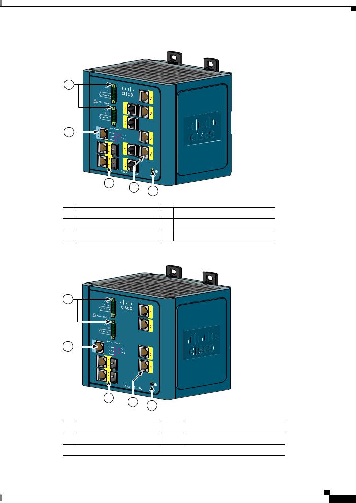
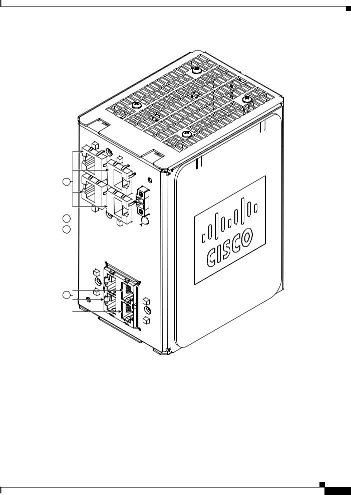
Figure 1-1 Cisco IE-3000-8TC Switch
1 |
2
|
|
|
|
|
|
201699 |
|
|
3 |
4 |
5 |
|
|
|
|
|
|
|
||
|
|
|
|
|
|
|
1 |
Power and relay connectors |
4 |
10/100 ports |
|||
2 |
Console port |
|
|
5 |
Protective ground connection |
|
3 |
Dual-purpose ports |
|
|
|
|
|
Figure 1-2 |
Cisco IE-3000-4TC Switch |
|||||
1 |
2
|
|
|
|
|
201700 |
|
3 |
4 |
5 |
|
|
|
|
|
|
||
|
|
|
|
|
|
1 |
Power and relay connectors |
4 |
10/100 ports |
||
2 |
Console port |
|
|
5 |
Protective ground connection |
3 |
Dual-purpose ports |
|
|
|
|
Cisco IE 3000 Switch Hardware Installation Guide
1-3
Chapter 1 Overview
Front-Panel Description
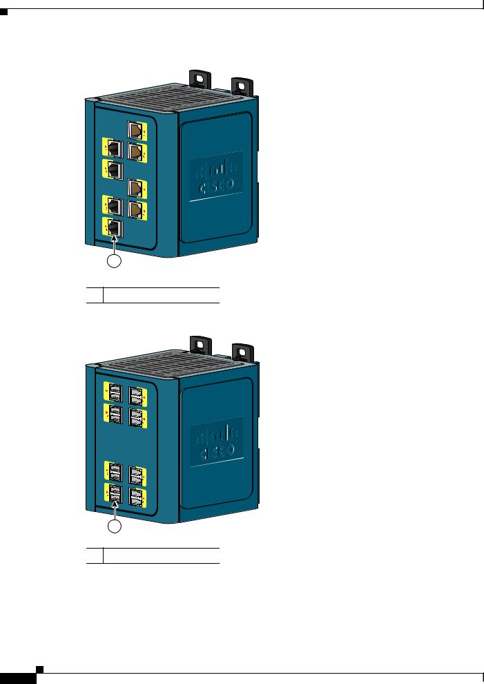
Figure 1-3 Cisco IEM-3000-8TM Expansion Module
201702
1
1 10/100 ports
Figure 1-4 Cisco IEM-3000-8FM Expansion Module
201701
1
1 100BASE-FX ports
Cisco IE 3000 Switch Hardware Installation Guide
1-4
Chapter 1 Overview
Front-Panel Description
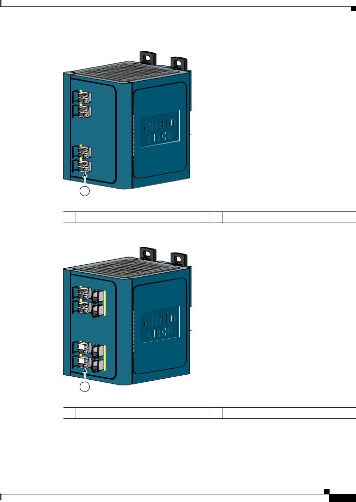
Figure 1-5 Cisco IEM-3000-4SM Expansion Module
1
2
3
4
1
 345668
1 100BASE-X SFP ports
Figure 1-6 Cisco IEM-3000-8SM Expansion Module
1 
 5
5
 6
6
3 

 7
7
4 

 8
8
1
 345667
1 100BASE-X SFP ports
Cisco IE 3000 Switch Hardware Installation Guide
1-5
Chapter 1 Overview
Front-Panel Description
Figure 1-7 Cisco IEM-3000-4PC PoE Expansion Module
1
2

 346705 3
1 DC Input terminal block |
3 PoE ports |
2 POE STATUS LED
Cisco IE 3000 Switch Hardware Installation Guide
1-6
Chapter 1 Overview
Front-Panel Description
Figure 1-8 Cisco IEM-3000-4PC-4TC PoE Expansion Module
1 |
2
3

 346704 4
1 |
10/100 Non-PoE ports |
3 |
POE STATUS LED |
|
|
|
|
2 |
DC-Input terminal block |
4 |
PoE ports |
|
|
|
|
Cisco IE 3000 Switch Hardware Installation Guide
1-7

Chapter 1 Overview
Front-Panel Description
10/100 Ports
You can set the 10/100 ports to operate at 10 or 100 Mb/s in full-duplex or half-duplex mode. You can also set these ports for speed and duplex autonegotiation in compliance with IEEE 802.3AB. (The default setting is autonegotiate.) When set for autonegotiation, the port senses the speed and duplex settings of the attached device and advertises its own capabilities. If the connected device also supports autonegotiation, the switch port negotiates the best connection (that is, the fastest line speed that both devices support and full-duplex transmission if the attached device supports it) and configures itself accordingly. In all cases, the attached device must be within 328 feet (100 meters). 100BASE-TX traffic requires Category 5 cable. 10BASE-T traffic can use Category 3 or Category 4 cables.
When connecting the switch to workstations, servers, routers, and Cisco IP Phones, be sure that the cable is a straight-through cable.
For copper ports, you can use the mdix auto interface configuration command in the command-line interface (CLI) to enable the automatic medium-dependent interface crossover (auto-MDIX) feature. When the auto-MDIX feature is enabled, the switch detects the required cable type for copper Ethernet connections and configures the interfaces accordingly. For configuration information for this feature, see the switch software configuration guide or the switch command reference.
Dual-Purpose Ports
A dual-purpose port can be configured as either a 10/100/1000 port or as an SFP module port. Only one port can be active at a time. If both ports are connected, the SFP module port has priority.
You can set the 10/100/1000 ports to operate at 10, 100, or 1000 Mb/s in full-duplex or half-duplex mode. You can configure them as fixed 10, 100, or 1000 Mb/s (Gigabit) Ethernet ports and can configure the duplex setting. (See the switch software configuration for more information.)
You can use Gigabit Ethernet SFP modules to establish fiber-optic connections to other switches. These transceiver modules are field-replaceable, providing the uplink interfaces when inserted in an SFP module slot. You use fiber-optic cables with LC connectors to connect to a fiber-optic SFP module.
For more information about these SFP modules, see the “SFP Modules” section on page 1-8, your SFP module documentation or the release note for your switch software.
SFP Modules
The switch Ethernet SFP modules provide connections to other devices. These field-replaceable transceiver modules provide the uplink interfaces.The modules have LC connectors for fiber-optic connections or RJ-45 connectors for copper connections. You can use any combination of the supported SFP modules listed in Table 1-2.
Cisco IE 3000 Switch Hardware Installation Guide
1-8

Chapter 1 Overview
Front-Panel Description
Table 1-2 |
Maximum Operating Temperature |
|
|
|
|
||
Type of SFP Module |
Model |
||
|
|
|
|
Rugged and Industrial SFPs |
• |
GLC-SX-MM-RGD |
|
–40 to 140°F (–40 to 60°C) |
• |
GLC-LX-SM-RGD |
|
|
|
||
|
|
• |
GLC-FE-100LX-RGD |
|
|
• |
GLC-FE-100FX-RGD |
|
|
• GLC-ZX-SM-RGD |
|
|
|
• GLC-BX40-D-I with digital optical monitoring |
|
|
|
|
(DOM) support |
|
|
• GLC-BX40-DA-I with DOM support |
|
|
|
• GLC-BX80-D-I with DOM support |
|
|
|
• GLC-BX40-U-I with DOM support |
|
|
|
• GLC-BX80-U-I with DOM support |
|
|
|
|
|
Commercial SFPs |
• |
GLC-BX-D with DOM support |
|
32 to 113°F (0 to 45°C) |
• |
GLC-BX-U with DOM support |
|
|
|
||
|
|
• |
GLC-FE-100LX |
|
|
• |
GLC-FE-100BX-D |
|
|
• |
GLC-FE-100BX-U |
|
|
• |
GLC-FE-100FX |
|
|
• |
GLC-FE-100EX |
|
|
• |
GLC-FE-100ZX |
|
|
• CWDM SFP with DOM support |
|
|
|
• DWDM SFP with DOM support |
|
|
|
• |
GLC-T |
|
|
|
|
Extended temperature SFPs |
• |
SFP-GE-L with DOM support |
|
23 to 140°F (–5 to 60°C) |
• |
SFP-GE-S with DOM support |
|
|
|
||
|
|
• SFP-GE-Z with DOM support |
|
|
|
• GLC-SX-MMD with DOM support |
|
|
|
• GLC-EX-SMD with DOM support |
|
|
|
• GLC-LH-MMD with DOM support |
|
|
|
• GLC-ZX-SMD with DOM support |
|
|
|
|
|
For the most up-to-date list of supported SFP models for Cisco Industrial Ethernet switches, see http://www.cisco.com/en/US/docs/interfaces_modules/transceiver_modules/compatibility/matrix/OL_ 6981.html#wp138176
For information about SFP modules, see your SFP module documentation and the “Installing and Removing SFP Transceivers” section on page 2-41. For cable specifications, see Appendix C, “Cable and Connectors.”
Cisco IE 3000 Switch Hardware Installation Guide
1-9
Chapter 1 Overview
Front-Panel Description
100BASE-FX Ports
The IEEE 802.3u 100BASE-FX ports provide full-duplex 100 Mb/s connectivity over multimode fiber (MMF) cables. These ports use a small-form-factor fixed (SFF) fiber-optic transceiver module that accepts a dual LC connector. The cable can be up to 1.24 miles (2 km) in length.
100BASE-X Ports
The IEEE 802.3u 100BASE-X ports provide full-duplex 100 Mb/s connectivity over both single-mode (SMF) and multimode fiber (MMF) cables. These ports use a small-form-factor pluggable (SFP) fiber-optic transceiver module that accepts a dual LC connector (except in the case of the GLC-FE-100BX-U and GLC-FE-100BX-D SFP transceivers). With the GLC-FE-100ZX SFP transceiver installed, cable runs of up to 49.6 miles (80 km) are supported.
PoE Ports
The IEM-3000-4PC and the IEM-3000-4PC-4TC expansion modules provide 10/100BASE-T PoE capability to the IE3000 base switch. Both expansion modules support up to 4 PoE (802.3af) or 4 PoE+ (802.3at) devices. The PoE expansion modules require a dedicated power supply for PoE power.
Power and Relay Connector
You connect the DC power and alarm signals to the switch through two front panel connectors. One connector provides primary DC power (supply A) and the major alarm signal, and a second connector (supply B) provides secondary power and the minor alarm signal. The two connectors are physically identical and are in the upper left side of the front panel. See Figure 1-2.
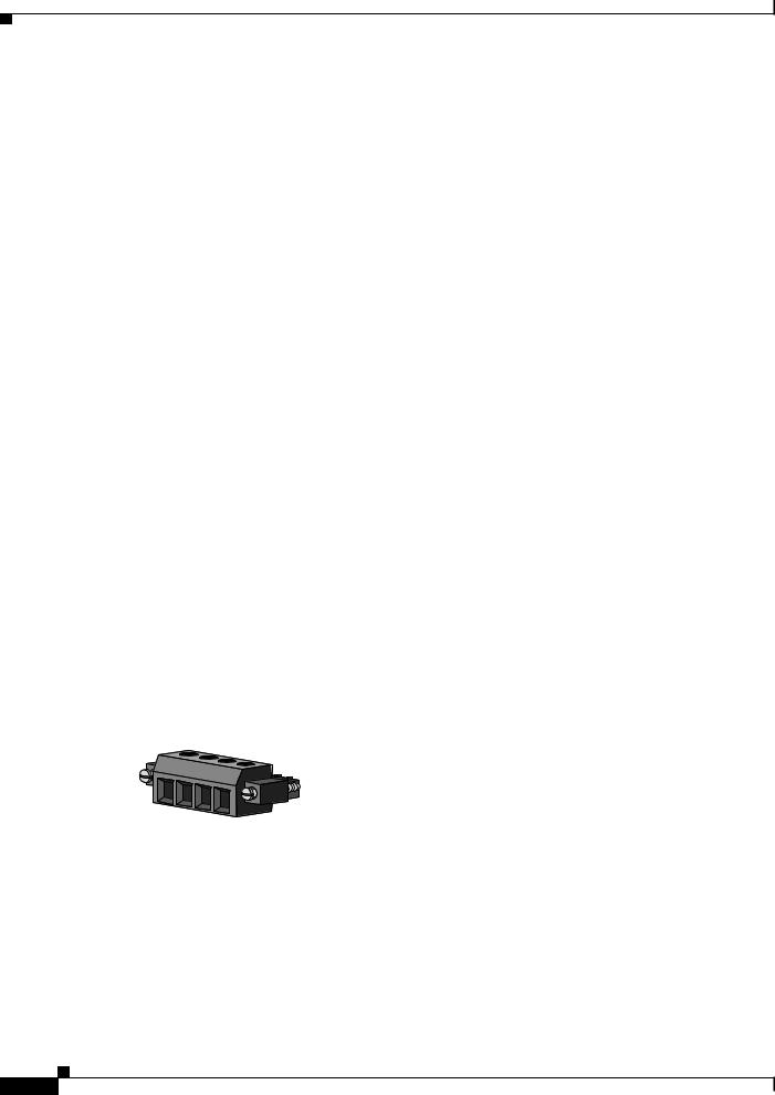
The switch accessory pack includes the mating power and relay connectors. These connectors provide screw terminals for terminating the DC power and alarm wire and the connector plugs into the power and relay receptacles on the front panel. The positive DC power connection is labeled V, and the return connection is labeled RT (see Figure 1-9).
Figure 1-9 Power and Relay Connector
V |
RT |
A |
A |
|
|||
|
|
||
|
|
|
201815
The switch can operate with a single power source or with dual power sources. When both power sources are operational, the switch draws power from the DC source with the higher voltage. If one of the two power sources fail, the other continues to power the switch.
The power and relay connectors also provide an interface for two independent alarm relays: the major and the minor alarms. The relays can be activated for environmental, power supply, and port status alarm conditions and can be configured to indicate an alarm with either open or closed contacts. The relay itself is normally open, so under power failure conditions, the contacts are open. From the CLI, you can associate any alarm condition with one or with both alarm relays.
Cisco IE 3000 Switch Hardware Installation Guide
1-10
Chapter 1 Overview
Front-Panel Description
Alarm relays often control an external alarm device, such as a bell or a light. To connect an external alarm device to the relay, you must connect two relay contact wires to complete an electrical circuit. Both alarm terminals on the power and relay connector are labeled A, and you can connect them without regard to polarity.
See the switch software configuration guide for instructions on configuring the alarm relays.
For more information about the power and relay connector, see Appendix C, “Cable and Connectors.”
You can get replacement power and relay connectors (PWR-IE3000-CNCT=) by calling Cisco Technical Support.
Console Port
You can connect a switch to a PC through the console port and the supplied RJ-45-to-DB-9 adapter cable. If you want to connect a switch to a terminal, you need to provide an RJ-45-to-DB-25 female DTE adapter. You can order a kit (part number ACS-DSBUASYN=) with that adapter from Cisco Systems. For console-port and adapter-pinout information, see the “Two Twisted-Pair Cable Pinouts” section on page C-8.
LEDs
You can use the LEDs to monitor the switch status, activity, and performance. Figure 1-10 to Figure 1-13 show the front panel LEDs, and the following sections describe them.
All LEDs are visible through the GUI management applications—the Cisco Network Assistant application for multiple switches and the device manager GUI for a single switch. The switch software configuration guide describes how to use the CLI to configure and to monitor individual switches and switch clusters.
Cisco IE 3000 Switch Hardware Installation Guide
1-11

Front-Panel Description
Figure 1-10 LEDs on the Cisco IE 3000 Switch
1
2
3
4
|
5 |
6 |
7 |
|
8 |
|
|
|
|
|
|
|
|
|
|
1 |
Express setup button |
|
5 |
|
Dual-purpose uplink port LED |
||
|
|
|
|
|
|
|
|
2 |
System LED |
|
|
6 |
|
Pwr B LED |
|
|
|
|
|
|
|
|
|
3 |
Alarm LED |
|
|
7 |
|
Pwr A LED |
|
|
|
|
|
|
|
|
|
4 |
Setup LED |
|
|
8 |
|
Port LED |
|
|
|
|
|
|
|
|
|
|
|
Figure 1-11 |
|
|
LEDs on the Cisco IEM-3000-8TM Module |
||
1
1 10/100 port LED
Cisco IE 3000 Switch Hardware Installation Guide
Chapter 1 Overview
201703
201706
1-12
Chapter 1 Overview
Front-Panel Description
Figure 1-12 LEDs on the Cisco IEM-3000-8FM Module
1
 201705
1 100BASE -FX port LEDs
Figure 1-13 LEDs on the Cisco IEM-3000-8SM Module
3 

 7
7
4 

 8
8
1 

 5
5
2 

 6
6
3 

 7
7
4 

 8
8
1
1 100BASE-X port LEDs
 345669
Note The port numbering sequence is the same for the IEM-3000-4SM expansion module.
Cisco IE 3000 Switch Hardware Installation Guide
1-13

Chapter 1 Overview
Front-Panel Description
The LED arrangement on the IEM-3000-4PC PoE expansion module is similar to the LED arrangement on the IEM-3000-4PC-4TC PoE expansion module except that the IEM-3000-4PC module does not have the four additional non-PoE ports with their associated port LEDs.
Setup LED
The Setup LED displays the express setup mode for the initial configuration. Table 1-3 lists the LED colors and their meanings.
Table 1-3 |
Setup LED |
|
|
|
|
Color |
|
Setup Status |
|
|
|
Off (dark) |
|
Switch is configured as a managed switch. |
|
|
|
Solid green |
|
Switch is in initial setup. |
|
|
|
Blinking green |
|
Switch is in initial setup, in recovery, or initial setup is |
|
|
incomplete. |
|
|
|
Solid red |
|
Switch failed to start initial setup or recovery because |
|
|
there is no available switch port to which to connect the |
|
|
management station. Disconnect a device from a switch |
|
|
port, and then press the Express Setup button. |
|
|
|
System LED
The System LED shows whether the system is receiving power and is functioning properly.
Table 1-4 lists the system LED colors and their meanings.
Table 1-4 |
System LED |
|
|
|
|
Color |
|
System Status |
|
|
|
Off |
|
System is not powered on. |
|
|
|
Green |
|
System is operating normally. |
|
|
|
Red |
|
Switch is not functioning properly. |
|
|
|
Alarm LED
Table 1-5 lists the alarm LED colors and their meanings.
Table 1-5 |
Alarm Status LED |
|
|
Color |
System Status |
|
|
Off |
Alarms are not configured, or the switch is off. |
|
|
Green |
Alarms are configured. |
|
|
Blinking red |
Switch has detected a major alarm. |
|
|
Red |
Switch has detected a minor alarm. |
|
|
Cisco IE 3000 Switch Hardware Installation Guide
1-14

Chapter 1 Overview
Front-Panel Description
Power Status LED
The switch can operate with one or two DC power sources. Each DC input has an associated LED that shows the status of the corresponding DC input. If power is present on the circuit, the LED is green. If power is not present, the LED color depends on the alarm configuration. If alarms are configured, the LED is red when power is not present; otherwise, the LED is off.
If the switch has dual power sources, the switch draws power from the power source with the higher voltage. If the one of the DC sources fails, the alternate DC source powers the switch, and the corresponding power status LED is green. The power status for the failed DC source is either off or red, depending on the alarm configuration.
Table 1-6 lists the power status LED colors and meanings.
Table 1-6 |
Power Status LEDs |
|
|
Color |
System Status |
|
|
Off |
Power is not present on the circuit, or the system is not powered up. |
|
|
Green |
Power is present on the associated circuit. |
|
|
Red |
Power is not present on the associated circuit, and the power supply alarm is |
|
configured. |
|
|
Note The Pwr A and Pwr B LEDs show that power is not present on the switch if the power input drops below the low valid level. The power status LEDs only show that power is present if the voltage at the switch input exceeds the valid level. The difference, or hysteresis, ensures that the power status LEDs do not oscillate at values near 18 V.
For information about the power LED colors during the power-on self-test (POST), see the “Verifying Switch Operation” section on page 2-13.
10/100 Port Status LEDs
Each 10/100 port has a port status LED, also called a port LED, as shown in Figure 1-10, Figure 1-11, and Figure 1-12. Table 1-7 displays LED information about the switch and the individual ports.
Table 1-7 |
10/100 Port Status LEDs |
|
|
|
|
Color |
|
System Status |
|
|
|
Off |
|
No link. |
|
|
|
Solid green |
|
Link present. |
|
|
|
Blinking green |
|
Activity. Port is sending or receiving data. |
|
|
|
Blinking |
|
A link blocked by Spanning Tree Protocol (STP) is |
amber |
|
sending or receiving data. |
|
|
|
Cisco IE 3000 Switch Hardware Installation Guide
1-15

Chapter 1 Overview
Front-Panel Description
Table 1-7 |
10/100 Port Status LEDs (continued) |
|
|
|
|
Color |
|
System Status |
|
|
|
Alternating |
|
Link fault. Error frames can affect connectivity, and errors |
green-amber |
|
such as excessive collisions, CRC errors, and alignment and |
|
|
jabber errors are monitored for a link-fault indication. |
|
|
|
Solid amber |
|
Port is not forwarding. Port was disabled by management, an |
|
|
address violation, or STP. |
|
|
Note After a port is reconfigured, the port LED can remain |
|
|
amber for up to 30 seconds while STP checks the |
|
|
switch for possible loops. |
|
|
|
100Base-FX Port Status LEDs
These LEDs display information about the individual ports. See Table 1-8.
Table 1-8 |
100BASE-FX MM Uplink Port Status LEDs |
|
|
|
|
Color |
|
System Status |
|
|
|
Off |
|
No link. |
|
|
|
Solid green |
|
Link is present. |
|
|
|
Blinking green |
|
Activity. Port is sending or receiving data. |
|
|
|
Blinking amber |
|
A link blocked by Spanning Tree Protocol (STP) is sending or receiving |
|
|
data. |
|
|
|
Alternating green-amber |
Link is faulty. |
|
|
|
|
Solid amber |
|
Link is disabled. |
|
|
|
Dual-Purpose Port LEDs
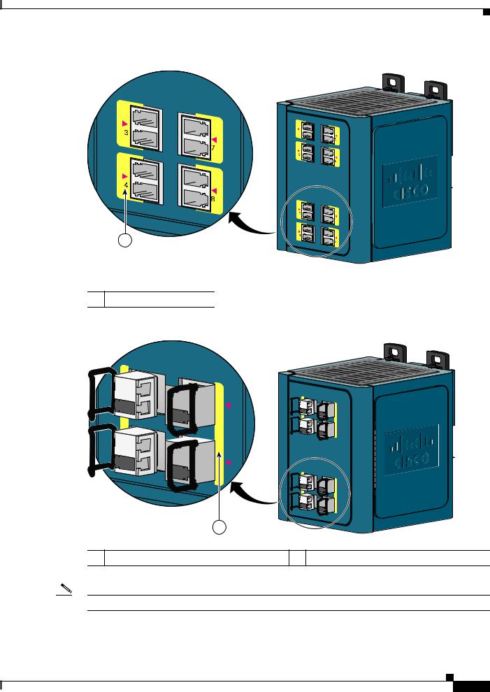
Figure 1-14 shows the LEDs on a dual-purpose port. You can configure each port as either a 10/100/1000 port through the RJ-45 connector or as an SFP module, but not both at the same time. The LEDs show how the port is being used (Ethernet or SFP module).
The LED colors have the same meanings as described in Table 1-7.
Figure 1-14 Dual-Purpose Port LEDs
1 2 3 4
1
203660
1 |
RJ-45 connector |
3 |
SFP module port in-use LED |
|
|
|
|
2 |
RJ-45 port in-use LED |
4 |
SFP module slot |
|
|
|
|
Cisco IE 3000 Switch Hardware Installation Guide
1-16

Chapter 1 Overview
Front-Panel Description
100BASE-X SFP Port LEDs
The 100BASE-X SFP port LEDs are located on the two SFP expansion modules. The LED colors have the same meanings as described in Table 1-7.
PoE Status LED
The PoE status LED on the front panel of the IEM-3000-4PC and the IEM-3000-4PC-4TC PoE expansion modules displays the functionality and status of the PoE ports. The LED colors and meanings are listed in Table 1-9.
Table 1-9 |
PoE Status LED Colors and Meanings |
|
||||
|
|
|
|
|||
Color |
|
PoE Status |
|
|||
|
|
|
|
|||
Off |
|
PoE is off. If the powered device is receiving power from an AC power source, |
|
|||
|
|
the port LED is off even if the powered device is connected to the switch port. |
|
|||
|
|
|
|
|
||
Green |
|
|
PoE is on. The port LED is green only when the switch port is providing power. |
|
||
|
|
|
||||
Alternating green |
PoE is denied because providing power to the powered device will exceed the |
|
||||
and amber |
|
power capacity of the expansion module. |
|
|||
|
|
|
|
|
||
Flashing amber |
|
|
PoE is off due to a fault. |
|
||
|
|
|
|
|
|
|
|
|
Caution Noncompliant cabling or powered devices can cause a PoE port fault. |
|
|||
|
|
|
|
|
Use only standard-compliant cabling to connect Cisco prestandard IP |
|
|
|
|
|
|
Phones and wireless access points or IEEE 802.3af-compliant devices. |
|
|
|
|
|
|
You must remove any cable or device that causes a PoE fault. |
|
|
|
|
|
|
||
|
|
|
|
|||
Amber |
|
PoE for the port is disabled. (PoE is enabled by default.) |
|
|||
|
|
|
|
|
|
|
10/100BASE-T PoE and Non-PoE Port LEDs
The 10/100BASE-T PoE and non-PoE port status LEDs on the front panel of the IEM-3000-4PC and the IEM-3000-4PC-4TC PoE expansion modules display the functionality and status of the individual ports on the expansion modules.
Table 1-10 |
10/100BASE-T Port Status LEDs for the PoE Expansion Modules |
|
|
|
|
Color |
|
Port Status |
|
|
|
Off |
|
Port is not connected. |
|
|
|
Flashing amber |
|
Link negotiation in progress on the port. |
|
|
|
Flashing green |
|
Link is up and there is data transfer in progress on the port. |
|
|
|
Amber |
|
Link negotiation failure on the port. |
|
|
|
Green |
|
Link is up but there is no data transfer. |
|
|
|
Cisco IE 3000 Switch Hardware Installation Guide
1-17

Chapter 1 Overview
Compact Flash Memory Card
Compact Flash Memory Card
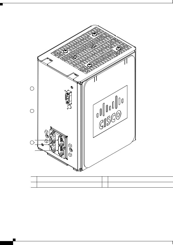
The switch supports a compact flash memory card that makes it possible to replace a failed switch without reconfiguring the new switch. The slot for the compact flash memory card is on the bottom of the switch. See Figure 1-15.
Note For more information on inserting and removing the compact flash memory card, see the “Installing or Removing the Compact Flash Memory Card” section on page 2-12.
Cisco IE 3000 Switch Hardware Installation Guide
1-18
Chapter 1 Overview
Rear-Panel Description
Figure 1-15 Compact Flash Memory Card Slot
201832
|
Bottom |
1 |
of switch |
|
Note You can obtain replacement flash memory cards (CF-IE3000=) by calling Cisco Technical Support.
Rear-Panel Description
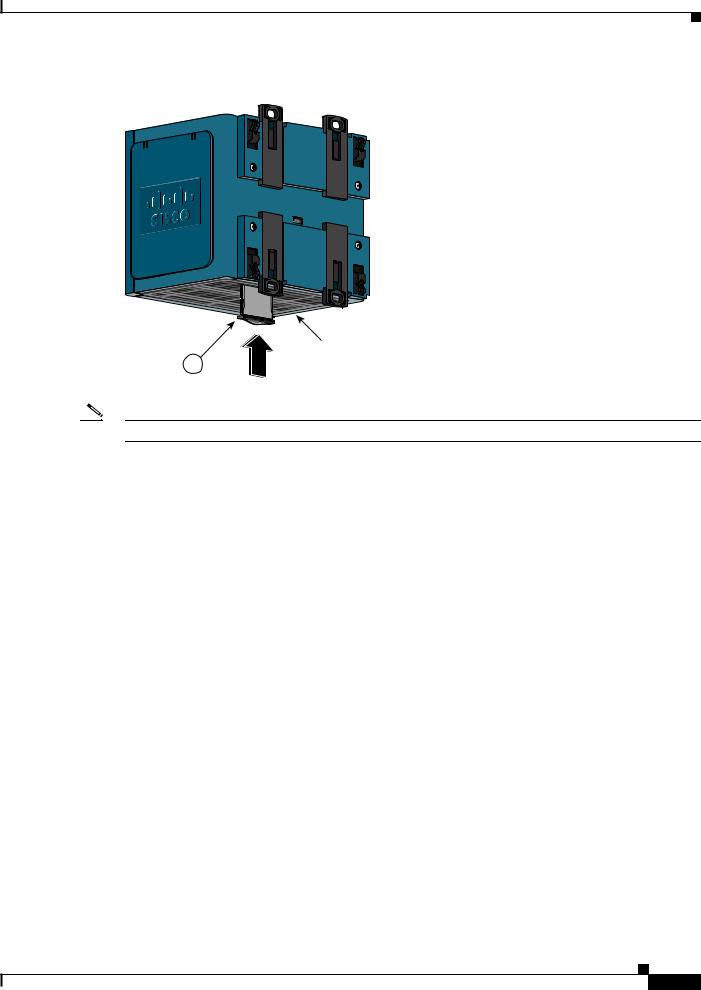
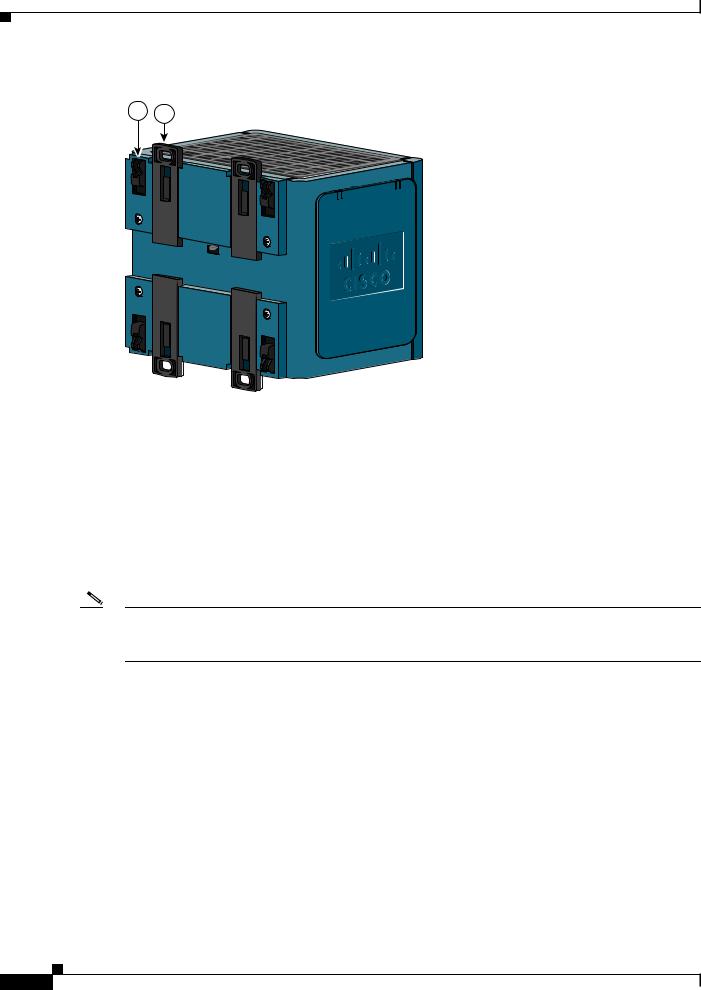
The rear panel of the switch, modules, and power converter have latches for installation on either a DIN rail or a wall. See Figure 1-16. The latches slide outward to position the switch over a DIN rail and slide inward to secure the switch to a DIN rail. The feet stabilize the switch when it is mounted on the wall.
Cisco IE 3000 Switch Hardware Installation Guide
1-19
Chapter 1 Overview
Power Converter (Optional)
Figure 1-16 Cisco IE 3000 Switch Rear Panel
2 1
201697
1 |
DIN rail latch |
2 |
Foot in recessed position |
|
|
|
|
Power Converter (Optional)
The switch can be used with an optional AC/DC power converter. The power converter (PWR-IE3000-AC) can supply 24-VDC power to one switch and up to two modules. The power converter is mounted on the side of a switch and provides power to the switch through a preassembled power cable.
Note The power converter (PWR-IE3000-AC=) is sold separately.
You can get a replacement power cable (PWR-IE3000-CLP=) by calling Cisco Technical Support.
For installation and connection procedures for the power converter, see the “Connecting the Switch to the Power Converter” section on page 2-48.
Cisco IE 3000 Switch Hardware Installation Guide
1-20
Loading...