


 Loading...
Cisco IE 3000 Switch Hardware
Installation Guide
June 2008
Americas Headquarters
Cisco Systems, Inc. 170 West Tasman Drive
San Jose, CA 95134-1706 USA http://www.cisco.com Tel: 408 526-4000
800 553-NETS (6387) Fax: 408 527-0883
Text Part Number: OL-13017-01
THE SPECIFICATIONS AND INFORMATION REGARDING THE PRODUCTS IN THIS MANUAL ARE SUBJECT TO CHANGE WITHOUT NOTICE. ALL STATEMENTS, INFORMATION, AND RECOMMENDATIONS IN THIS MANUAL ARE BELIEVED TO BE ACCURATE BUT ARE PRESENTED WITHOUT WARRANTY OF ANY KIND, EXPRESS OR IMPLIED. USERS MUST TAKE FULL RESPONSIBILITY FOR THEIR APPLICATION OF ANY PRODUCTS.
THE SOFTWARE LICENSE AND LIMITED WARRANTY FOR THE ACCOMPANYING PRODUCT ARE SET FORTH IN THE INFORMATION PACKET THAT SHIPPED WITH THE PRODUCT AND ARE INCORPORATED HEREIN BY THIS REFERENCE. IF YOU ARE UNABLE TO LOCATE THE SOFTWARE LICENSE OR LIMITED WARRANTY, CONTACT YOUR CISCO REPRESENTATIVE FOR A COPY.
The following information is for FCC compliance of Class A devices: This equipment has been tested and found to comply with the limits for a Class A digital device, pursuant to part 15 of the FCC rules. These limits are designed to provide reasonable protection against harmful interference when the equipment is operated in a commercial environment. This equipment generates, uses, and can radiate radio-frequency energy and, if not installed and used in accordance with the instruction manual, may cause harmful interference to radio communications. Operation of this equipment in a residential area is likely to cause harmful interference, in which case users will be required to correct the interference at their own expense.
The following information is for FCC compliance of Class B devices: The equipment described in this manual generates and may radiate radio-frequency energy. If it is not installed in accordance with Cisco’s installation instructions, it may cause interference with radio and television reception. This equipment has been tested and found to comply with the limits for a Class B digital device in accordance with the specifications in part 15 of the FCC rules. These specifications are designed to provide reasonable protection against such interference in a residential installation. However, there is no guarantee that interference will not occur in a particular installation.
Modifying the equipment without Cisco’s written authorization may result in the equipment no longer complying with FCC requirements for Class A or Class B digital devices. In that event, your right to use the equipment may be limited by FCC regulations, and you may be required to correct any interference to radio or television communications at your own expense.
You can determine whether your equipment is causing interference by turning it off. If the interference stops, it was probably caused by the Cisco equipment or one of its peripheral devices. If the equipment causes interference to radio or television reception, try to correct the interference by using one or more of the following measures:
•Turn the television or radio antenna until the interference stops.
•Move the equipment to one side or the other of the television or radio.
•Move the equipment farther away from the television or radio.
•Plug the equipment into an outlet that is on a different circuit from the television or radio. (That is, make certain the equipment and the television or radio are on circuits controlled by different circuit breakers or fuses.)
Modifications to this product not authorized by Cisco Systems, Inc. could void the FCC approval and negate your authority to operate the product.
The Cisco implementation of TCP header compression is an adaptation of a program developed by the University of California, Berkeley (UCB) as part of UCB’s public domain version of the UNIX operating system. All rights reserved. Copyright © 1981, Regents of the University of California.
NOTWITHSTANDING ANY OTHER WARRANTY HEREIN, ALL DOCUMENT FILES AND SOFTWARE OF THESE SUPPLIERS ARE PROVIDED “AS IS” WITH ALL FAULTS. CISCO AND THE ABOVE-NAMED SUPPLIERS DISCLAIM ALL WARRANTIES, EXPRESSED OR IMPLIED, INCLUDING, WITHOUT LIMITATION, THOSE OF MERCHANTABILITY, FITNESS FOR A PARTICULAR PURPOSE AND NONINFRINGEMENT OR ARISING FROM A COURSE OF DEALING, USAGE, OR TRADE PRACTICE.
IN NO EVENT SHALL CISCO OR ITS SUPPLIERS BE LIABLE FOR ANY INDIRECT, SPECIAL, CONSEQUENTIAL, OR INCIDENTAL DAMAGES, INCLUDING, WITHOUT LIMITATION, LOST PROFITS OR LOSS OR DAMAGE TO DATA ARISING OUT OF THE USE OR INABILITY TO USE THIS MANUAL, EVEN IF CISCO OR ITS SUPPLIERS HAVE BEEN ADVISED OF THE POSSIBILITY OF SUCH DAMAGES.
CCDE, CCENT, Cisco Eos, Cisco Lumin, Cisco StadiumVision, the Cisco logo, DCE, and Welcome to the Human Network are trademarks; Changing the Way We Work, Live, Play, and Learn is a service mark; and Access Registrar, Aironet, AsyncOS, Bringing the Meeting To You, Catalyst, CCDA, CCDP, CCIE, CCIP, CCNA, CCNP, CCSP, CCVP, Cisco, the Cisco Certified Internetwork Expert logo, Cisco IOS, Cisco Press, Cisco Systems, Cisco Systems Capital, the Cisco Systems logo, Cisco Unity, Collaboration Without Limitation, EtherFast, EtherSwitch, Event Center, Fast Step, Follow Me Browsing, FormShare, GigaDrive, HomeLink, Internet Quotient, IOS, iPhone, iQ Expertise, the iQ logo, iQ Net Readiness Scorecard, iQuick Study, IronPort, the IronPort logo, LightStream, Linksys, MediaTone, MeetingPlace, MGX, Networkers, Networking Academy, Network Registrar, PCNow, PIX, PowerPanels, ProConnect, ScriptShare, SenderBase, SMARTnet, Spectrum Expert, StackWise, The Fastest Way to Increase Your Internet Quotient, TransPath, WebEx, and the WebEx logo are registered trademarks of Cisco Systems, Inc. and/or its affiliates in the United States and certain other countries.
All other trademarks mentioned in this document or Website are the property of their respective owners. The use of the word partner does not imply a partnership relationship between Cisco and any other company. (0804R)
Any Internet Protocol (IP) addresses used in this document are not intended to be actual addresses. Any examples, command display output, and figures included in the document are shown for illustrative purposes only. Any use of actual IP addresses in illustrative content is unintentional and coincidental.
Cisco IE 3000 Switch Hardware Installation Guide
© 2008 Cisco Systems, Inc. All rights reserved.

|
|
|
|
|
|
|
|
|
|
C O N T E N T S |
|||
|
|
Preface ix |
|
|
|
|
|
|
|
|
|
|
|
|
|
Audience |
ix |
|
|
|
|
|
|
|
|
|
|
|
|
Purpose |
ix |
|
|
|
|
|
|
|
|
|
|
|
|
Conventions |
ix |
|
|
|
|
|
|
|
|
|
|
|
|
Related Publications |
x |
|
|
|
|
|
|
||||
|
|
Obtaining Documentation, Obtaining Support, and Security Guidelines x |
|||||||||||
|
Overview |
|
|
|
|
|
|
|
|
|
|
|
|
C H A P T E R 1 |
1-1 |
|
|
|
|
|
|
|
|
|
|
||
|
|
Overview |
1-1 |
|
|
|
|
|
|
|
|
|
|
|
|
Switch Models |
1-2 |
|
|
|
|
|
|
|
|||
|
|
Front-Panel Description |
|
1-2 |
|
|
|
|
|
||||
|
|
10/100 Ports |
|
1-5 |
|
|
|
|
|
|
|
||
|
|
Dual-Purpose Ports |
1-5 |
|
|
|
|
|
|||||
|
|
100BASE-FX Ports |
|
1-5 |
|
|
|
|
|
||||
|
|
Power and Relay Connector |
1-5 |
|
|
|
|||||||
|
|
Console Port |
|
1-6 |
|
|
|
|
|
|
|
||
|
|
LEDs |
1-6 |
|
|
|
|
|
|
|
|
|
|
|
|
|
Setup LED |
1-8 |
|
|
|
|
|
||||
|
|
|
System LED |
1-9 |
|
|
|
|
|
||||
|
|
|
Alarm LED |
1-9 |
|
|
|
|
|
||||
|
|
|
Power Status LED |
1-9 |
|
|
|
|
|||||
|
|
|
10/100 Port Status LEDs |
1-10 |
|
|
|
||||||
|
|
|
100Base-FX Port Status LEDs 1-10 |
||||||||||
|
|
|
Dual-Purpose Port LEDs |
1-11 |
|
|
|
||||||
|
|
Compact Flash Memory Card |
1-11 |
|
|
|
|||||||
|
|
Rear-Panel Description |
|
1-12 |
|
|
|
|
|
||||
|
|
Power Converter (Optional) |
1-13 |
|
|
|
|
||||||
|
|
Management Options |
|
1-14 |
|
|
|
|
|
||||
|
|
Network Configurations |
1-15 |
|
|
|
|
||||||
|
Switch Installation |
|
|
|
|
|
|
|
|
|
|||
C H A P T E R 2 |
|
2-1 |
|
|
|
|
|
|
|
||||
|
|
Preparing for Installation |
2-1 |
|
|
|
|
||||||
|
|
Warnings |
2-2 |
|
|
|
|
|
|
|
|||
|
|
|
|
|
|
|
|
|
|
Cisco IE 3000 Switch Hardware Installation Guide |
|
|
|
|
|
|
|
|
|
|
|
|
|
|
|||
|
OL-13017-01 |
|
|
|
|
|
|
|
|
|
|
iii |
|
|
|
|
|
|
|
|
|
|
|
|
|
||

Contents
Installation Guidelines |
2-3 |
|
|
||
Environment and Enclosure Guidelines: 2-3 |
|
||||
Other Guidelines |
2-3 |
|
|
|
|
Verifying Package Contents |
2-5 |
|
|
||
Adding Modules to the Switch |
2-5 |
|
|
||
Expansion Module Configurations |
2-5 |
|
|||
Connecting Modules |
2-8 |
|
|
|
|
Installing or Removing the Compact Flash Memory Card |
2-10 |
||||
Verifying Switch Operation |
2-11 |
|
|
||
Connecting a PC or a Terminal to the Console Port |
2-12 |
||||
Connecting the Protective Ground and DC Power |
2-13 |
||||
Grounding the Switch |
2-13 |
|
|
||
Wiring the DC Power Source |
2-16 |
|
|||
Attach the Power and Relay Connector to the Switch 2-21 |
|||||
Running POST |
2-22 |
|
|
|
|
Power On the Switch |
2-22 |
|
|
||
Verify POST Results |
2-22 |
|
|
||
Disconnect Power |
2-22 |
|
|
||
Installing the Switch |
2-23 |
|
|
|
|
Installing the Switch on a DIN Rail |
2-23 |
|
|||
Installing the Switch on the Wall |
2-27 |
|
|||
Installing the Switch in a Rack |
2-29 |
|
|
Removing the Switch from a DIN Rail or a Rack 2-31 |
|||
Connecting Power and Alarm Circuits |
2-32 |
|
|
Wiring the Protective Ground and DC Power |
2-32 |
||
Wiring the External Alarms |
2-33 |
|
|
Connecting Destination Ports |
2-36 |
|
|
Connecting to 10/100 and 10/100/1000 Ports |
2-36 |
||
Installing and Removing SFP Modules 2-37 |
|
||
Installing SFP Modules into SFP Module Slots
Removing SFP Modules from SFP Module Slots
|
|
|
Connecting to SFP Modules |
2-41 |
|
|
|
|
|
|
Connecting to a Dual-Purpose Port |
2-42 |
|
|
|
|
|
|
Connecting to 100BASE-FX Ports |
2-43 |
|
|
|
|
|
|
Connecting the Switch to the Power Converter |
2-44 |
|
||
|
|
|
Attaching the Power Converter to the Switch |
2-45 |
|
||
|
|
|
Installing the Power Converter on a DIN Rail, Wall, or Rack Adapter 2-46 |
||||
|
|
|
Connecting the DC Power Clip |
2-46 |
|
|
|
|
|
|
Connecting the Power Converter to an AC Power Source 2-47 |
||||
|
|
|
Cisco IE 3000 Switch Hardware Installation Guide |
|
|
|
|
|
|
|
|
|
|
|
|
|
|
|
|
|
|
|
|
|
iv |
|
|
|
|
OL-13017-01 |
|
|
|
|
|
|
|
||

Contents
|
|
Preparing the AC Power Cord |
2-47 |
|
|
|
|
|||||||
|
|
Connecting the AC Power Cord to the Power Converter 2-48 |
||||||||||||
|
|
Connecting the Power Converter to a DC Power Source 2-51 |
||||||||||||
|
|
Applying Power to the Power Converter |
2-53 |
|
|
|
||||||||
|
|
Where to Go Next |
2-53 |
|
|
|
|
|
|
|
|
|
||
|
Troubleshooting |
|
|
|
|
|
|
|
|
|
|
|
|
|
C H A P T E R 3 |
3-1 |
|
|
|
|
|
|
|
|
|
|
|
||
|
|
Diagnosing Problems |
|
3-1 |
|
|
|
|
|
|
|
|
|
|
|
|
Verify Switch POST Results |
|
3-1 |
|
|
|
|
|
|
||||
|
|
Verify Switch LEDs |
3-2 |
|
|
|
|
|
|
|
|
|||
|
|
Verify Switch Connections |
|
3-2 |
|
|
|
|
|
|
||||
|
|
Bad or Damaged Cable |
|
3-2 |
|
|
|
|
|
|
||||
|
|
Ethernet and Fiber Cables |
3-2 |
|
|
|
|
|
||||||
|
|
Link Status |
3-3 |
|
|
|
|
|
|
|
|
|
||
|
|
Transceiver Issues |
3-3 |
|
|
|
|
|
|
|
||||
|
|
Port and Interface Settings |
3-3 |
|
|
|
|
|||||||
|
|
Ping End Device |
3-3 |
|
|
|
|
|
|
|
|
|||
|
|
Spanning Tree Loops |
3-4 |
|
|
|
|
|
|
|||||
|
|
Verify Switch Performance |
|
3-4 |
|
|
|
|
|
|
||||
|
|
Speed, Duplex, and Autonegotiation |
3-4 |
|
|
|
||||||||
|
|
Autonegotiation and NIC |
3-4 |
|
|
|
|
|
||||||
|
|
Cabling Distance |
3-5 |
|
|
|
|
|
|
|
|
|||
|
|
How to Clear the Switch IP Address and Configuration 3-5 |
||||||||||||
|
|
How to Recover Passwords |
3-5 |
|
|
|
|
|
|
|
|
|||
|
|
Finding the Switch Serial Number |
3-6 |
|
|
|
|
|
||||||
|
Technical Specifications |
|
|
|
|
|
|
|
|
|
||||
A P P E N D I X A |
A-1 |
|
|
|
|
|
|
|
|
|||||
|
Installation In a Hazardous Environment |
|
|
|
|
|
||||||||
A P P E N D I X B |
B-1 |
|
|
|
|
|||||||||
|
|
Preparing for Installation |
B-1 |
|
|
|
|
|
|
|
|
|||
|
|
Warnings |
B-2 |
|
|
|
|
|
|
|
|
|
|
|
|
|
North American Hazardous Location Approval |
B-5 |
|||||||||||
|
|
EMC Environmental Conditions for Products Installed in the European Union B-5 |
||||||||||||
|
|
Installation Guidelines |
B-5 |
|
|
|
|
|
|
|
||||
|
|
Environment and Enclosure Guidelines: B-5 |
||||||||||||
|
|
Other Guidelines |
B-6 |
|
|
|
|
|
|
|
|
|||
|
|
Verifying Package Contents |
|
B-7 |
|
|
|
|
|
|||||
|
|
Adding Modules to the Switch |
B-8 |
|
|
|
|
|
|
|||||
|
|
|
|
|
|
|
|
|
|
|
Cisco IE 3000 Switch Hardware Installation Guide |
|
|
|
|
|
|
|
|
|
|
|
|
|
|
|
|||
|
OL-13017-01 |
|
|
|
|
|
|
|
|
|
|
|
v |
|
|
|
|
|
|
|
|
|
|
|
|
|
|
||

Contents
Expansion Module Configurations |
B-9 |
|
|
|
||||
Connecting Modules |
B-11 |
|
|
|
|
|
||
Installing or Removing the Compact Flash Memory Card |
B-13 |
|||||||
Verifying Switch Operation |
B-14 |
|
|
|
|
|
||
Connecting a PC or a Terminal to the Console Port |
|
B-15 |
||||||
Connecting the Protective Ground and DC Power |
B-16 |
|||||||
Grounding the Switch |
B-17 |
|
|
|
|
|||
Wiring the DC Power Source |
|
B-19 |
|
|
|
|||
Attach the Power and Relay Connector to the Switch B-24 |
||||||||
Running POST |
B-25 |
|
|
|
|
|
|
|
Power On the Switch |
B-25 |
|
|
|
|
|
||
Verify POST Results |
B-25 |
|
|
|
|
|
||
Disconnect Power |
B-25 |
|
|
|
|
|
||
Installing the Switch |
B-26 |
|
|
|
|
|
|
|
Installing the Switch on a DIN Rail |
B-27 |
|
|
|
||||
Installing the Switch on a Wall |
B-31 |
|
|
|
||||
Installing the Switch in a Rack |
B-33 |
|
|
|
||||
Removing the Switch from a DIN Rail or a Rack |
B-35 |
|||||||
Connecting Power and Alarm Circuits |
|
B-36 |
|
|
|
|||
Information about the Sealed Relay Device |
B-37 |
|
|
|||||
Wiring the Protective Ground and DC Power |
B-37 |
|
||||||
Wiring the External Alarms |
B-38 |
|
|
|
|
|||
Connecting Destination Ports |
B-41 |
|
|
|
|
|
||
Connecting to 10/100 and 10/100/1000 Ports |
B-41 |
|
||||||
Installing and Removing SFP Modules B-42 |
|
|
|
|||||
Installing SFP Modules into SFP Module Slots |
B-43 |
|||||||
Removing SFP Modules from SFP Module Slots |
B-44 |
|||||||
Connecting to SFP Modules B-45 |
|
|
|
|
||||
Connecting to a Dual-Purpose Port |
B-46 |
|
|
|
||||
Connecting to 100BASE-FX Ports |
|
B-48 |
|
|
|
|||
Connecting the Switch to the Power Converter
Attaching the Power Converter to the Switch B-49
Installing the Power Converter on a DIN Rail, Wall, or Rack Adapter B-52
Connecting the DC Power Clip B-52
Connecting the Power Converter to an AC Power Source B-53
|
|
|
Preparing the AC Power Cord B-53 |
|
|
|
|
|
Connecting the AC Power Cord to the Power Converter |
B-54 |
|
|
|
|
Connecting the Power Converter to a DC Power Source B-57 |
|
|
|
|
|
Applying Power to the Power Converter B-59 |
|
|
|
|
|
Cisco IE 3000 Switch Hardware Installation Guide |
|
|
|
|
|
|
|
|
|
|
|
|
|
|
|
vi |
|
|
OL-13017-01 |
|
|
|
|
|
||

Contents
|
Where to Go Next |
B-59 |
|
|
Cable and Connectors |
|
|
A P P E N D I X C |
C-1 |
||
|
Connector Specifications |
C-1 |
|
|
10/100 Ports |
C-1 |
|
|
Connecting to 10BASE-T- and 100BASE-TX-Compatible Devices C-1 |
||
|
Connecting to 1000BASE-T Devices C-1 |
||
|
100BASE-FX Ports |
C-3 |
|
|
SFP Module Ports |
C-3 |
|
|
Dual-Purpose Ports |
C-4 |
|
|
Console Port |
C-4 |
|
|
Cable and Adapter Specifications |
C-4 |
|
|
|
SFP Module Cable Specifications |
C-4 |
|
|
|
Two Twisted-Pair Cable Pinouts |
C-5 |
|
|
|
Four Twisted-Pair Cable Pinouts for 1000BASE-T Ports |
C-6 |
||
|
Crossover Cable and Adapter Pinouts C-7 |
|
||
|
Identifying a Crossover Cable |
C-7 |
|
|
|
Four Twisted-Pair Cable Pinouts for 1000BASE-T Ports |
C-7 |
||
|
Adapter Pinouts C-8 |
|
|
|
|
Configuring the Switch with the CLI-Based Setup Program |
|
||
A P P E N D I X D |
D-1 |
|||
|
Accessing the CLI from the Console Port |
D-1 |
|
|
|
Entering the Initial Configuration Information D-2 |
|
||
IP Settings D-2
Completing the Setup Program D-2
I N D E X
Cisco IE 3000 Switch Hardware Installation Guide
|
OL-13017-01 |
vii |
|

Contents
Cisco IE 3000 Switch Hardware Installation Guide
|
viii |
OL-13017-01 |
|
|
|

Preface
Audience
This guide is for the networking or computer technician responsible for installing Cisco IE 3000 series switches. We assume that you are familiar with the concepts and terminology of Ethernet and local area networking.
Purpose
This guide documents the hardware features of the Cisco IE 3000 switches. It describes the physical and performance characteristics of each switch, explains how to install a switch, and provides troubleshooting information.
This guide does not describe system messages that you might receive or how to configure your switch. For more information, see the switch getting started guide, the switch software configuration guide, the switch command reference, and the switch system message guide on the Cisco.comTechnical Support and Documentation home page. For information about the standard Cisco IOS Release 12.1 or 12.2 commands, see the Cisco IOS documentation set from the Cisco.com home page at
Technical Support and Documentation > Documentation. On the Cisco Documentation home page, select Release 12.1 or 12.2 from the Cisco IOS Software drop-down list.
Conventions
This document uses the following conventions and symbols for notes, cautions, and warnings.
Note Means reader take note. Notes contain helpful suggestions or references to materials not contained in this manual.
Caution Means reader be careful. In this situation, you might do something that could result in equipment damage or loss of data.
Cisco IE 3000 Switch Hardware Installation Guide
|
OL-13017-01 |
ix |
|

Preface
Warning This warning symbol means danger. You are in a situation that could cause bodily injury. Before you work on any equipment, be aware of the hazards involved with electrical circuitry and be familiar with standard practices for preventing accidents. Use the statement number provided at the end of each warning to locate its translation in the translated safety warnings that accompanied this device.
Statement 1071
The safety warnings for this product are translated into several languages in the Regulatory Compliance and Safety Information for the Cisco IE 3000 Switch that ships with the product. The EMC regulatory statements are also included in that guide.
Related Publications
Before installing, configuring, or upgrading the switch, see the release notes on Cisco.com for the latest information.
These documents provide complete information about the switch and are available on Cisco.com:
•Cisco IE 3000 Switch Getting Started Guide
•Regulatory Compliance and Safety Information for the Cisco IE 3000 Switch
•Release Notes for the Cisco IE 3000 Switch
•Cisco IE 3000 Switch Software Configuration Guide
•Cisco IE 3000 Switch Command Reference
•Cisco IE 3000 Switch System Message Guide
•Device manager online help (available on the switch)
•Cisco Small Form-Factor Pluggable Modules Installation Notes
These compatibility matrix documents are available from this Cisco.com site:
http://www.cisco.com/en/US/products/hw/modules/ps5455/products_device_support_tables_list.html
•Cisco Gigabit Ethernet Transceiver Modules Compatibility Matrix (not orderable but available on Cisco.com)
•Cisco Small Form-Factor Pluggable Modules Compatibility Matrix (not orderable but available on Cisco.com)
Obtaining Documentation, Obtaining Support, and Security
Guidelines
For information on obtaining documentation, obtaining support, providing documentation feedback, security guidelines, and also recommended aliases and general Cisco documents, see the monthly What’s New in Cisco Product Documentation, which also lists all new and revised Cisco technical documentation, at:
http://www.cisco.com/en/US/docs/general/whatsnew/whatsnew.html
Cisco IE 3000 Switch Hardware Installation Guide
|
x |
OL-13017-01 |
|
|
|
C H A P T E R 1
Overview
This chapter provides these topics that describe the Cisco Industrial Ethernet (IE) 3000 switch, hereafter referred to as the switch.
This chapter provides a functional overview of the switches and covers these topics:
•Overview, page 1-1
•Switch Models, page 1-2
•Front-Panel Description, page 1-2
•Compact Flash Memory Card, page 1-11
•Rear-Panel Description, page 1-12
•Power Converter (Optional), page 1-13
•Management Options, page 1-14
•Network Configurations, page 1-15
Overview
The Cisco IE 3000 switch provides a rugged and secure switching infrastructure for harsh environments. It is suitable for industrial Ethernet applications, including factory automation, intelligent transportation systems (ITSs), substations, and other deployments in harsh environments.
You can connect these switches to office networking devices like Cisco IP Phones, Cisco Wireless Access Points workstations, and other devices such as servers, routers, and other switches. In industrial environments, you can connect any Ethernet-enabled industrial communication devices, including programmable logic controllers (PLCs), human-machine interfaces (HMIs), drives, sensors, traffic signal controllers, and intelligent electronic devices (IEDs).
You can mount the switch on a DIN rail in an industrial enclosure, on a wall or panel, and with some restrictions, in a standard 19-inch rack. Its components are designed to withstand extremes in temperature, vibration, and shock that are common in an industrial environment.
Note The switch does not have cooling fans.
Cisco IE 3000 Switch Hardware Installation Guide
|
OL-13017-01 |
1-1 |
|
|
|

Chapter 1 Overview
Switch Models
Switch Models
Table 1-1 describes the switch and the expansion modules. The Cisco IE-3000-4TC and the Cisco IE-3000-8TC are the switch models, and the Cisco IEM-3000-8TM and the
Cisco IEM-3000-8FM are expansion modules that you can connect to increase the number of ports. For instructions on how to connect the expansion modules to the switch, see the “Adding Modules to the Switch” section on page 2-5.
.
Table 1-1 Cisco IE 3000 Switch Models
Switch Model |
Description |
|
|
|
|
Cisco IE-3000-4TC |
4 10/100BASE-T Ethernet ports and 2 dual-purpose ports, each with a |
|
|
10/100/1000BASE-T copper port and an SFP (small form-factor pluggable) |
|
|
module slot |
|
|
|
|
Cisco IE-3000-8TC |
8 10/100BASE-T Ethernet ports and 2 dual-purpose ports |
|
|
|
|
Cisco IEM-3000-8TM |
Expansion module with 8 |
10/100BASE-T copper Ethernet ports |
|
|
|
Cisco IEM-3000-8FM |
Expansion module with 8 |
100BASE-FX fiber-optic Ethernet ports |
|
|
|
Front-Panel Description
This section describes the front panel and includes these sections:
•10/100 Ports, page 1-5
•Dual-Purpose Ports, page 1-5
•100BASE-FX Ports, page 1-5
•Power and Relay Connector, page 1-5
•Console Port, page 1-6
•LEDs, page 1-6
The switch front panel contains the ports, the LEDs, and the power and relay connectors. Figure 1-1 to Figure 1-4 show the switch and expansion module front panels.
Cisco IE 3000 Switch Hardware Installation Guide
1-2 |
OL-13017-01 |
|
|
Chapter 1 Overview
Front-Panel Description
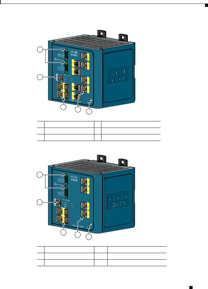
Figure 1-1 Cisco IE-3000-8TC Switch
1 |
2
|
|
|
|
|
|
201699 |
|
|
3 |
4 |
5 |
|
|
|
|
|
|
|
||
|
|
|
|
|
|
|
1 |
Power and relay connectors |
4 |
10/100 ports |
|||
2 |
Console port |
|
|
5 |
Protective ground connection |
|
3 |
Dual-purpose ports |
|
|
|
|
|
Figure 1-2 |
Cisco IE-3000-4TC Switch |
|||||
1 |
2
|
|
|
|
|
201700 |
|
3 |
4 |
5 |
|
|
|
|
|
|
||
|
|
|
|
|
|
1 |
Power and relay connectors |
4 |
10/100 ports |
||
2 |
Console port |
|
|
5 |
Protective ground connection |
3 |
Dual-purpose ports |
|
|
|
|
Cisco IE 3000 Switch Hardware Installation Guide
|
OL-13017-01 |
1-3 |
|
|
|
Chapter 1 Overview
Front-Panel Description
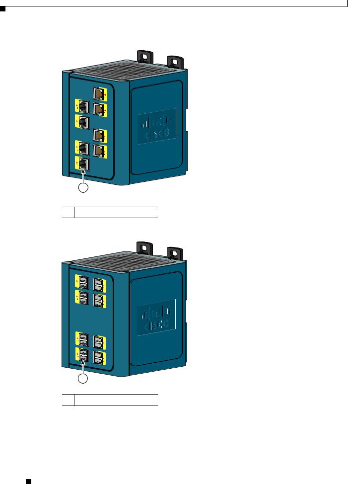
Figure 1-3 Cisco IEM-3000-8TM Module
201702
1
1 10/100 ports
Figure 1-4 Cisco IEM-3000-8FM Module
201701
1
1 100BASE-FX ports
Cisco IE 3000 Switch Hardware Installation Guide
1-4 |
OL-13017-01 |
|
|

Chapter 1 Overview
Front-Panel Description
10/100 Ports
You can set the 10/100 ports to operate at 10 or 100 Mb/s in full-duplex or half-duplex mode. You can also set these ports for speed and duplex autonegotiation in compliance with IEEE 802.3AB. (The default setting is autonegotiate.) When set for autonegotiation, the port senses the speed and duplex settings of the attached device and advertises its own capabilities. If the connected device also supports autonegotiation, the switch port negotiates the best connection (that is, the fastest line speed that both devices support and full-duplex transmission if the attached device supports it) and configures itself accordingly. In all cases, the attached device must be within 328 feet (100 meters). 100BASE-TX traffic requires Category 5 cable. 10BASE-T traffic can use Category 3 or Category 4 cables.
When connecting the switch to workstations, servers, routers, and Cisco IP Phones, be sure that the cable is a straight-through cable.
You can use the mdix auto interface configuration command in the command-line interface (CLI) to enable the automatic medium-dependent interface crossover (auto-MDIX) feature. When the auto-MDIX feature is enabled, the switch detects the required cable type for copper Ethernet connections and configures the interfaces accordingly. For configuration information for this feature, see the switch software configuration guide or the switch command reference.
Dual-Purpose Ports
A dual-purpose port can be configured as either a 10/100/1000 port or as an SFP module port. Only one port can be active at a time. If both ports are connected, the SFP module port has priority.
You can set the 10/100/1000 ports to operate at 10, 100, or 1000 Mb/s in full-duplex or half-duplex mode. You can configure them as fixed 10, 100, or 1000 Mb/s (Gigabit) Ethernet ports and can configure the duplex setting. (See the switch software configuration for more information.)
You can use Gigabit Ethernet SFP modules to establish fiber-optic connections to other switches. These transceiver modules are field-replaceable, providing the uplink interfaces when inserted in an SFP module slot. You use fiber-optic cables with LC connectors to connect to a fiber-optic SFP module.
For more information about these SFP modules, see your SFP module documentation or the release note for your switch software.
100BASE-FX Ports
The IEEE 802.3u 100BASE-FX ports provide full-duplex 100 Mb/s connectivity over multimode fiber (MMF) cables. These ports use a small-form-factor fixed (SFF) fiber-optic transceiver module that accepts a dual LC connector. The cable can be up to 1.24 miles (2 km) in length.
Power and Relay Connector
You connect the DC power and alarm signals to the switch through two front panel connectors. One connector provides primary DC power (supply A) and the major alarm signal, and a second connector (supply B) provides secondary power and the minor alarm signal. The two connectors are physically identical and are in the upper left side of the front panel. See Figure 1-2.
Cisco IE 3000 Switch Hardware Installation Guide
|
OL-13017-01 |
1-5 |
|
|
|

Chapter 1 Overview
Front-Panel Description
The switch accessory pack includes the mating power and relay connectors. These connectors provide screw terminals for terminating the DC power and alarm wire and the connector plugs into the power and relay receptacles on the front panel. The positive DC power connection is labeled V, and the return connection is labeled RT (see Figure 1-5).
Figure 1-5 Power and Relay Connector
V |
RT A |
A |
|
||
|
|
201815
The switch can operate with a single power source or with dual power sources. When both power sources are operational, the switch draws power from the DC source with the higher voltage. If one of the two power sources fail, the other continues to power the switch.
The power and relay connectors also provide an interface for two independent alarm relays: the major and the minor alarms. The relays can be activated for environmental, power supply, and port status alarm conditions and can be configured to indicate an alarm with either open or closed contacts. The relay itself is normally open, so under power failure conditions, the contacts are open. From the CLI, you can associate any alarm condition with one or with both alarm relays.
Alarm relays often control an external alarm device, such as a bell or a light. To connect an external alarm device to the relay, you must connect two relay contact wires to complete an electrical circuit. Both alarm terminals on the power and relay connector are labeled A, and you can connect them without regard to polarity.
See the switch software configuration guide for instructions on configuring the alarm relays.
For more information about the power and relay connector, see Appendix C, “Cable and Connectors.”
You can get replacement power and relay connectors (PWR-IE3000-CNCT=) by calling Cisco Technical Support.
Console Port
You can connect a switch to a PC through the console port and the supplied RJ-45-to-DB-9 adapter cable. If you want to connect a switch to a terminal, you need to provide an RJ-45-to-DB-25 female DTE adapter. You can order a kit (part number ACS-DSBUASYN=) with that adapter from Cisco Systems. For console-port and adapter-pinout information, see the “Two Twisted-Pair Cable Pinouts” section on page C-5.
LEDs
You can use the LEDs to monitor the switch status, activity, and performance. Figure 1-6 to Figure 1-9 show the front panel LEDs, and the following sections describe them.
All LEDs are visible through the GUI management applications—the Cisco Network Assistant application for multiple switches and the device manager GUI for a single switch. The switch software configuration guide describes how to use the CLI to configure and to monitor individual switches and switch clusters.
Cisco IE 3000 Switch Hardware Installation Guide
1-6 |
OL-13017-01 |
|
|

Chapter 1 Overview
Figure 1-6 LEDs on the Cisco IE 3000 Switch
1
2
3
4
|
5 |
6 |
7 |
|
8 |
|
|
|
|
|
|
|
|
|
|
1 |
Express setup button |
|
5 |
|
Dual-purpose uplink port LED |
||
|
|
|
|
|
|
|
|
2 |
System LED |
|
|
6 |
|
Pwr B LED |
|
|
|
|
|
|
|
|
|
3 |
Alarm LED |
|
|
7 |
|
Pwr A LED |
|
|
|
|
|
|
|
|
|
4 |
Setup LED |
|
|
8 |
|
Port LED |
|
|
|
|
|
|
|
|
|
|
|
Figure 1-7 |
|
|
LEDs on the Cisco IEM-3000-8TM Module |
||
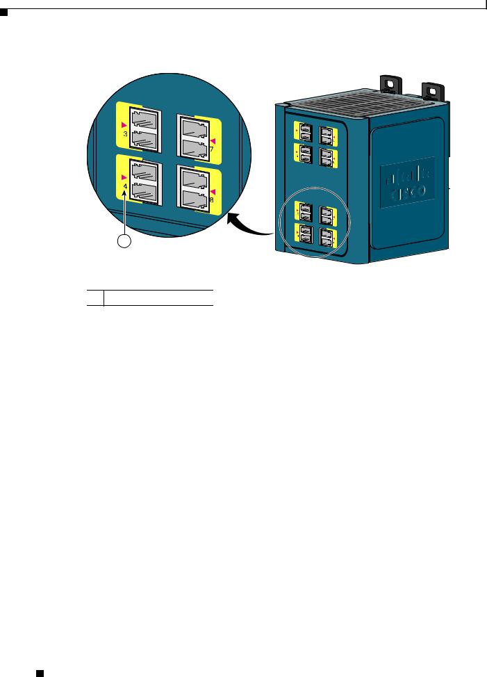
1
1 10/100 port LED
Front-Panel Description
201703
201706
Cisco IE 3000 Switch Hardware Installation Guide
|
OL-13017-01 |
1-7 |
|
|
|
Chapter 1 Overview
Front-Panel Description
Figure 1-8 LEDs on the Cisco IEM-3000-8FM Module
1
 201705
1 100BASE -FX port LEDs
Setup LED
The Setup LED displays the express setup mode for the initial configuration. Table 1-2 lists the LED colors and their meanings.
Table 1-2 |
Setup LED |
|
|
|
|
Color |
|
Setup Status |
|
|
|
Off (dark) |
|
Switch is configured as a managed switch. |
|
|
|
Solid green |
|
Switch is in initial setup. |
|
|
|
Blinking green |
|
Switch is in initial setup, in recovery, or initial setup is |
|
|
incomplete. |
|
|
|
Solid red |
|
Switch failed to start initial setup or recovery because |
|
|
there is no available switch port to which to connect the |
|
|
management station. Disconnect a device from a switch |
|
|
port, and then press the Express Setup button. |
|
|
|
Cisco IE 3000 Switch Hardware Installation Guide
1-8 |
OL-13017-01 |
|
|

Chapter 1 Overview
Front-Panel Description
System LED
The System LED shows whether the system is receiving power and is functioning properly.
Table 1-3 lists the system LED colors and their meanings.
Table 1-3 |
System LED |
|
|
|
|
Color |
|
System Status |
|
|
|
Off |
|
System is not powered on. |
|
|
|
Green |
|
System is operating normally. |
|
|
|
Red |
|
Switch is not functioning properly. |
|
|
|
Alarm LED
Table 1-4 lists the alarm LED colors and their meanings.
Table 1-4 |
Alarm Status LED |
|
|
Color |
System Status |
|
|
Off |
Alarms are not configured, or the switch is off. |
|
|
Green |
Alarms are configured. |
|
|
Blinking red |
Switch has detected a major alarm. |
|
|
Red |
Switch has detected a minor alarm. |
|
|
Power Status LED
The switch can operate with one or two DC power sources. Each DC input has an associated LED that shows the status of the corresponding DC input. If power is present on the circuit, the LED is green. If power is not present, the LED color depends on the alarm configuration. If alarms are configured, the LED is red when power is not present; otherwise, the LED is off.
If the switch has dual power sources, the switch draws power from the power source with the higher voltage. If the one of the DC sources fails, the alternate DC source powers the switch, and the corresponding power status LED is green. The power status for the failed DC source is either off or red, depending on the alarm configuration.
Table 1-5 lists the power status LED colors and meanings.
Table 1-5 |
Power Status LEDs |
|
|
Color |
System Status |
|
|
Off |
Power is not present on the circuit, or the system is not powered up. |
|
|
Green |
Power is present on the associated circuit. |
|
|
Red |
Power is not present on the associated circuit, and the power supply alarm is |
|
configured. |
|
|
Cisco IE 3000 Switch Hardware Installation Guide
|
OL-13017-01 |
1-9 |
|
|
|

Chapter 1 Overview
Front-Panel Description
|
|
|
Note |
The Pwr A and Pwr B LEDs show that power is not present on the switch if the power input drops below |
||||||
|
|
|
|
the low valid level. The power status LEDs only show that power is present if the voltage at the switch |
||||||
|
|
|
|
input exceeds the valid level. The difference, or hysteresis, ensures that the power status LEDs do not |
||||||
|
|
|
|
oscillate at values near 18 V. |
||||||
|
|
|
|
|
|
|
|
|
||
|
|
|
|
For information about the power LED colors during the power-on self-test (POST), see the “Verifying |
||||||
|
|
|
|
Switch Operation” section on page 2-11. |
||||||
10/100 Port Status LEDs |
|
|
|
|
|
|
||||
|
|
|
|
Each 10/100 port has a port status LED, also called a port LED, as shown in Figure 1-6, Figure 1-7, and |
||||||
|
|
|
|
Figure 1-8. Table 1-6 displays LED information about the switch and the individual ports. |
||||||
|
|
|
|
Table 1-6 |
10/100 Port Status LEDs |
|||||
|
|
|
|
|
|
|
|
|
|
|
|
|
|
|
Color |
|
System Status |
||||
|
|
|
|
|
|
|
|
|
|
|
|
|
|
|
Off |
|
No link. |
||||
|
|
|
|
|
|
|
|
|
|
|
|
|
|
|
Solid green |
|
Link present. |
||||
|
|
|
|
|
|
|
|
|
|
|
|
|
|
|
Blinking green |
|
Activity. Port is sending or receiving data. |
||||
|
|
|
|
|
|
|
|
|
|
|
|
|
|
|
Blinking |
|
A link blocked by Spanning Tree Protocol (STP) is |
||||
|
|
|
|
amber |
|
sending or receiving data. |
||||
|
|
|
|
|
|
|
|
|
|
|
|
|
|
|
Alternating |
|
Link fault. Error frames can affect connectivity, and errors |
||||
|
|
|
|
green-amber |
|
such as excessive collisions, CRC errors, and alignment and |
||||
|
|
|
|
|
|
jabber errors are monitored for a link-fault indication. |
||||
|
|
|
|
|
|
|
|
|
|
|
|
|
|
|
Solid amber |
|
Port is not forwarding. Port was disabled by management, an |
||||
|
|
|
|
|
|
address violation, or STP. |
||||
|
|
|
|
|
|
Note After a port is reconfigured, the port LED can remain |
||||
|
|
|
|
|
|
amber for up to 30 seconds while STP checks the |
||||
|
|
|
|
|
|
switch for possible loops. |
||||
|
|
|
|
|
|
|
|
|||
100Base-FX Port Status LEDs |
|
|
|
|
|
|
||||
|
|
|
|
These LEDs display information about the individual ports. See Table 1-7. |
||||||
|
|
|
|
Table 1-7 |
100BASE-FX MM Uplink Port Status LEDs |
|||||
|
|
|
|
|
|
|
|
|
||
|
|
|
|
Color |
|
|
System Status |
|||
|
|
|
|
|
|
|
|
|
||
|
|
|
|
Off |
|
|
No link. |
|||
|
|
|
|
|
|
|
|
|
||
|
|
|
|
Solid green |
|
|
Link is present. |
|||
|
|
|
|
|
|
|
|
|
||
|
|
|
|
Blinking green |
|
|
Activity. Port is sending or receiving data. |
|||
|
|
|
|
|
|
|
|
|
||
|
|
|
|
Blinking amber |
|
|
A link blocked by Spanning Tree Protocol (STP) is sending or receiving |
|||
|
|
|
|
|
|
|
data. |
|||
|
|
|
|
|
|
|
||||
|
|
|
|
Alternating green-amber |
Link is faulty. |
|||||
|
|
|
|
|
|
|
|
|
||
|
|
|
|
Solid amber |
|
|
Link is disabled. |
|||
|
|
|
|
|
|
|
||||
|
|
|
Cisco IE 3000 Switch Hardware Installation Guide |
|||||||
|
|
|
||||||||
|
1-10 |
|
|
|
|
|
|
OL-13017-01 |
|
|
|
|
|
|
|
||||||
Chapter 1 Overview
Compact Flash Memory Card
Dual-Purpose Port LEDs
Figure 1-9 shows the LEDs on a dual-purpose port. You can configure each port as either a 10/100/1000 port through the RJ-45 connector or as an SFP module, but not both at the same time. The LEDs show how the port is being used (Ethernet or SFP module).
The LED colors have the same meanings as described in Table 1-6.
Figure 1-9 Dual-Purpose Port LEDs
1 2 3 4
1
203660
1 |
RJ-45 connector |
3 |
SFP module port in-use LED |
|
|
|
|
2 |
RJ-45 port in-use LED |
4 |
SFP module slot |
|
|
|
|
Compact Flash Memory Card
The switch supports a compact flash memory card that makes it possible to replace a failed switch without reconfiguring the new switch. The slot for the compact flash memory card is on the bottom of the switch. See Figure 1-10.
Note For more information on inserting and removing the compact flash memory card, see the “Installing or Removing the Compact Flash Memory Card” section on page 2-10.
|
|
Cisco IE 3000 Switch Hardware Installation Guide |
|
|
|
|
|
|
|||
|
OL-13017-01 |
|
|
1-11 |
|
|
|
|
|
||
Chapter 1 Overview
Rear-Panel Description
Figure 1-10 Compact Flash Memory Card Slot
201832
|
Bottom |
1 |
of switch |
|
Note You can obtain replacement flash memory cards (CF-IE3000=) by calling Cisco Technical Support.
Rear-Panel Description
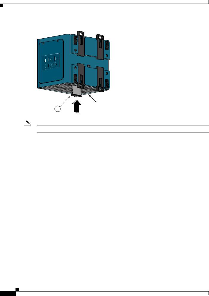
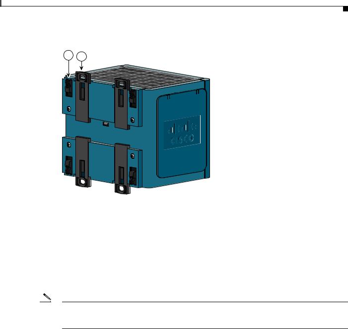
The rear panel of the switch, modules, and power converter have latches for installation on either a DIN rail or a wall. See Figure 1-11. The latches slide outward to position the switch over a DIN rail and slide inward to secure the switch to a DIN rail. The feet stabilize the switch when it is mounted on the wall.
|
Cisco IE 3000 Switch Hardware Installation Guide |
1-12 |
OL-13017-01 |
Chapter 1 Overview
Power Converter (Optional)
Figure 1-11 Cisco IE 3000 Switch Rear Panel
2 1
201697
1 |
DIN rail latch |
2 |
Foot in recessed position |
|
|
|
|
Power Converter (Optional)
The switch can be used with an optional AC/DC power converter. The power converter (PWR-IE3000-AC) can supply 24-VDC power to one switch and up to two modules. The power converter is mounted on the side of a switch and provides power to the switch through a preassembled power cable.
Note The power converter (PWR-IE3000-AC=) is sold separately.
You can get a replacement power cable (PWR-IE3000-CLP=) by calling Cisco Technical Support.
For installation and connection procedures for the power converter, see the “Connecting the Switch to the Power Converter” section on page 2-44.
|
|
Cisco IE 3000 Switch Hardware Installation Guide |
|
|
|
|
|
|
|||
|
OL-13017-01 |
|
|
1-13 |
|
|
|
|
|
||

Chapter 1 Overview
Management Options
Figure 1-12 displays the power converter.
Figure 1-12 Cisco IE 3000 Switch AC/DC Power Converter
1
2
3
|
|
202314 |
1 |
DC output connector |
3 AC/DC input power connector |
2 |
Status LED |
|
Management Options
The switch supports these management options:
•Cisco Network Assistant
Cisco Network Assistant is a PC-based network management GUI application optimized for LANs of small and medium-sized businesses. Through a GUI, users can configure and manage switch clusters or standalone switches. Cisco Network Assistant is available at no cost and can be downloaded from this URL:
http://www.cisco.com/go/networkassistant
For information on starting the Cisco Network Assistant application, see the Getting Started with Cisco Network Assistant guide on Cisco.com.
•Device Manager
You can use the device manager, which is in the switch memory, to manage individual and standalone switches. This web interface offers quick configuration and monitoring. You can access the device manager from anywhere in your network through a web browser. For more information, see the getting started guide and the device manager online help.
•Cisco IOS CLI
The switch CLI is based on Cisco IOS software and is enhanced to support desktop-switching features. You can fully configure and monitor the switch. You can access the CLI either by connecting your management station directly to the switch management port, or a console port, or by using Telnet from a remote management station. See the switch command reference on Cisco.com for more information.
|
Cisco IE 3000 Switch Hardware Installation Guide |
1-14 |
OL-13017-01 |

Chapter 1 Overview
Network Configurations
•CiscoWorks application
The CiscoWorks device-management application displays the switch image that you can use to set configuration parameters and to view the switch status and performance information. The CiscoView application, which you purchase separately, can be a standalone application or part of a Simple Network Management Protocol (SNMP) platform. See the CiscoView documentation for more information.
•SNMP network management
You can manage switches from a SNMP-compatible management station that is running platforms such as HP OpenView or SunNet Manager. The switch supports a comprehensive set of Management Information Base (MIB) extensions and four Remote Monitoring (RMON) groups. See the switch software configuration guide on Cisco.com and the documentation that came with your SNMP application for more information.
•Common Industrial Protocol
The Common Industrial Protocol (CIP) management objects are supported. The Cisco IE 3000 can be managed by CIP-based management tools, allowing the user to manage an entire industrial automation system with one tool.
Network Configurations
See the switch software configuration guide on Cisco.com for network configuration concepts and examples of using the switch to create dedicated network segments and interconnecting the segments through Gigabit Ethernet connections.
|
|
Cisco IE 3000 Switch Hardware Installation Guide |
|
|
|
|
|
|
|||
|
OL-13017-01 |
|
|
1-15 |
|
|
|
|
|
||

Chapter 1 Overview
Network Configurations
|
Cisco IE 3000 Switch Hardware Installation Guide |
1-16 |
OL-13017-01 |

C H A P T E R 2
Switch Installation
This chapter describes how to install your switch, interpret the power-on self-test (POST), and connect the switch to other devices.
Caution If your installation is in a hazardous environment, see Appendix B, “Installation In a Hazardous Environment” for instructions.
Read these topics, and perform the procedures in this order:
•Preparing for Installation, page 2-1
•Adding Modules to the Switch, page 2-5
•Installing or Removing the Compact Flash Memory Card, page 2-10
•Verifying Switch Operation, page 2-11
•Installing the Switch, page 2-23
•Connecting Power and Alarm Circuits, page 2-32
•Connecting Destination Ports, page 2-36
•Connecting the Switch to the Power Converter, page 2-44
•Where to Go Next, page 2-53
Preparing for Installation
This section provides information about these topics:
•Warnings, page 2-2
•Installation Guidelines, page 2-3
•Verifying Package Contents, page 2-5
Cisco IE 3000 Switch Hardware Installation Guide
|
OL-13017-01 |
2-1 |
|
|
|

Chapter 2 Switch Installation
Preparing for Installation
Warnings
These warnings are translated into several languages in the Regulatory Compliance and Safety
Information Guide.
Warning Before working on equipment that is connected to power lines, remove jewelry (including rings, necklaces, and watches). Metal objects will heat up when connected to power and ground and can cause serious burns or weld the metal object to the terminals. Statement 43
Warning Do not work on the system or connect or disconnect cables during periods of lightning activity.
Statement 1001
Warning Before performing any of the following procedures, ensure that power is removed from the DC circuit.
Statement 1003
Warning Read the installation instructions before you connect the system to its power source. Statement 1004
Warning This unit is intended for installation in restricted access areas. A restricted access area can be accessed only through the use of a special tool, lock and key, or other means of security.
Statement 1017
Warning This equipment must be grounded. Never defeat the ground conductor or operate the equipment in the absence of a suitably installed ground conductor. Contact the appropriate electrical inspection authority or an electrician if you are uncertain that suitable grounding is available. Statement 1024
Warning This unit might have more than one power supply connection. All connections must be removed to de-energize the unit. Statement 1028
Warning Only trained and qualified personnel should be allowed to install, replace, or service this equipment.
Statement 1030
Warning Ultimate disposal of this product should be handled according to all national laws and regulations.
Statement 1040
Warning For connections outside the building where the equipment is installed, the following ports must be connected through an approved network termination unit with integral circuit protection. 10/100/1000 Ethernet Statement 1044
Cisco IE 3000 Switch Hardware Installation Guide
2-2 |
OL-13017-01 |
|
|

Chapter 2 Switch Installation
Preparing for Installation
Warning To prevent the system from overheating, do not operate it in an area that exceeds the maximum recommended ambient temperature of:
140°F (60°C) Statement 1047
Warning Installation of the equipment must comply with local and national electrical codes. Statement 1074
Warning To prevent airflow restriction, allow clearance around the ventilation openings to be at least: 4.13 in. (105 mm). Statement 1076
Installation Guidelines
When determining where to place the switch, observe these guidelines.
Environment and Enclosure Guidelines:
Review these environmental and enclosure guidelines before installation:
•This equipment is intended for use in a Pollution Degree 2 industrial environment, in overvoltage Category II applications (as defined in IEC publication 60664-1), at altitudes up to 9842 ft (3 km) without derating.
•This equipment is considered Group 1, Class A industrial equipment, according to IEC/CISPR Publication 11. Without appropriate precautions, there may be potential difficulties ensuring electromagnetic compatibility in other environments due to conducted as well as radiated disturbance.
•This equipment is supplied as open-type equipment. It must be mounted within an enclosure that is suitably designed for those specific environmental conditions that will be present and appropriately designed to prevent personal injury resulting from accessibility to live parts. The enclosure must have suitable flame-retardant properties to prevent or minimize the spread of flame, complying with a flame-spread rating of 5VA, V2, V1, V0 (or equivalent) if nonmetallic. The interior of the enclosure must be accessible only by the use of a tool. Subsequent sections of this publication might contain additional information regarding specific enclosure-type ratings that are required to comply with certain product safety certifications.
Other Guidelines
These are other installation guidelines:
Caution Proper ESD protection is required whenever you handle Cisco equipment. Installation and maintenance personnel should be properly grounded by using ground straps to eliminate the risk of ESD damage to the switch.
Do not touch connectors or pins on component boards. Do not touch circuit components inside the switch. When not in use, store the equipment in appropriate static-safe packaging.
Cisco IE 3000 Switch Hardware Installation Guide
|
OL-13017-01 |
2-3 |
|
|
|

Chapter 2 Switch Installation
Preparing for Installation
•Personnel responsible for the application of safety-related programmable electronic systems (PES) shall be aware of the safety requirements in the application of the system and shall be trained in using the system.
•This product is grounded through the DIN rail to chassis ground. Use zinc-plated yellow-chromate steel DIN rail to assure proper grounding. The use of other DIN rail materials (such as aluminum, plastic, and so on) that can corrode, oxidize, or are poor conductors can result in improper or intermittent grounding. Secure the DIN rail to the mounting surface approximately every 7.8 in. (200 mm), and use end-anchors appropriately.
When determining where to place the switch, observe these guidelines:
•Before installing the switch, first verify that the switch is operational by powering it on and running POST. Follow the procedures in the “Verifying Switch Operation” section on page 2-11.
•For 10/100 ports and 10/100/1000 ports, the cable length from a switch to an attached device cannot exceed 328 feet (100 meters).
•For 100BASE-FX fiber-optic ports, the cable length from a switch to an attached device cannot exceed 6562 ft (2 km).
•Operating environment is within the ranges listed in Appendix A, “Technical Specifications.”
•Clearance to front and rear panels meets these conditions:
–Front-panel LEDs can be easily read.
–Access to ports is sufficient for unrestricted cabling.
–Front-panel direct current (DC) power and relay connector is within reach of the connection to the DC power source.
•Airflow around the switch and through the vents is unrestricted. To prevent the switch from overheating, there must be the following minimum clearances:
–Top and bottom: 4.13 in. (105 mm)
–Exposed side (not connected to the module): 3.54 in. (90 mm)
–Front: 2.56 in. (65 mm)
•Temperature surrounding the unit does not exceed 140°F (60°C).
Note When the switch is installed in an industrial enclosure, the temperature within the enclosure is greater than normal room temperature outside the enclosure.
The temperature inside the enclosure cannot exceed 140°F (60°C), the maximum ambient enclosure temperature of the switch.
•Cabling is away from sources of electrical noise, such as radios, power lines, and fluorescent lighting fixtures.
•Connect the unit only to a Class 2 DC power source.
Caution This equipment is only suitable for use in Class I, Division 2, Groups A, B, C, D, or nonhazardous locations.
Cisco IE 3000 Switch Hardware Installation Guide
2-4 |
OL-13017-01 |
|
|
Loading...