


 Loading...
Cisco IW3702 Access Point Getting Started Guide
Cisco IW3702 Access Point Getting Started Guide 2
Organization |
2 |
|
|
Conventions |
2 |
|
|
Overview |
3 |
|
|
Installation |
13 |
|
|
Antennas and RF Accessories 23 |
|||
Configuration |
41 |
|
|
Technical Specifications |
65 |
||
Ports and Connectors 75 |
|
||
Related Documentation |
78 |
||
Obtaining Documentation and Submitting a Service Request 78

Revised: January 22, 2020
Cisco IW3702 Access Point Getting Started Guide
This guide documents the hardware features of the Cisco IW3702 access point. It describes the physical and performance characteristics of each access point, and explains how to install and configure an access point.
This publication is for the network technicians who install and configure access points. You must be familiar with network structures, terms, and concepts.
The Cisco IW3702 access point is referred to as access point in this document.
Organization
This guide includes the following sections:
Section |
Description |
Conventions, on page 2 |
Describes text conventions used in this document. |
Overview, on page 3 |
Describes the major components and features of the access point. |
Installation, on page 13 |
Provides warnings, safety information, and installation information you need to install |
|
your access point. |
Antennas and RF Accessories, on page 23 Provides information about the antennas used by the access point and the antenna configurations deployed.
Configuration, on page 41 |
Describes the steps to configure the access point. |
Technical Specifications, on page 65 Lists technical specifications for the access point.
Ports and Connectors, on page 75 |
Describes the port and connector pinouts for the access point. |
Conventions
This document uses the following conventions.
Convention Indication
bold font |
Commands and keywords and user-entered text appear in bold font. |
italic font |
Document titles, new or emphasized terms, and arguments for which you supply values are in italic font. |
[ ] |
Elements in square brackets are optional. |
{x | y | z } |
Required alternative keywords are grouped in braces and separated by vertical bars. |
[ x | y | z ] |
Optional alternative keywords are grouped in brackets and separated by vertical bars. |
string |
A nonquoted set of characters. Do not use quotation marks around the string or the string will include the quotation |
|
marks. |
2
Convention |
Indication |
courier font |
Terminal sessions and information the system displays appear in courier font. |
< > |
Nonprinting characters such as passwords are in angle brackets. |
[ ] |
Default responses to system prompts are in square brackets. |
!, # |
An exclamation point (!) or a pound sign (#) at the beginning of a line of code indicates a comment line. |
Note Means reader take note . Notes contain helpful suggestions or references to material not covered in the manual.
Caution Means reader be careful. In this situation, you might perform an action that could result in equipment damage or loss of data.
Danger IMPORTANT SAFETY INSTRUCTIONSMeans danger. You are in a situation that could cause bodily injury. Before you work on any equipment, be aware of the hazards involved with electrical circuitry and be familiar with standard practices for preventing accidents. Use the statement number provided at the end of each warning to locate its translation in the translated safety warnings that accompanied this device.SAVE THESE INSTRUCTIONS
Overview
This document describes the Cisco IW3702 access point. The access point is an IEEE 802.11a/b/g/n/ac compliant, dual-band WiFi access point with external antennas.
The access point is IP67 rated, ruggedized, and certified for on-board rail and outdoor use-cases such as train and trackside, mining, intelligent transportation systems, and smart city applications. You can mount the access point on a DIN rail in an industrial enclosure. Its components are designed to withstand extremes in temperature, vibration, and shock common in industrial environments.
The access point features:
•IEEE 802.11a/b/g/n compliant operation
•IEEE 802.11ac Wave 1 support
•Dual-radio design for 2.4 GHz and/or 5 GHz bands
•4x4 multiple-input multiple-output (MIMO) technology with three spatial streams
•Cisco CleanAir support for 20, 40, and 80 MHz channels
•DC input port (M12 connector)
•2 Power over Ethernet (PoE) ports with M12 X-code connectors:
•1 x PoE-IN Gigabit Ethernet port compliant with IEEE 802.3at POE+ PD
•1 x PoE-OUT Gigabit Ethernet port compliant with IEEE 802.3af POE PSE
3

•RS232 console port with cover (RJ-45 connector)
•4 antenna ports (N connector-female)
•Rugged IP67 rated housing and -40 to 167°F (-40 to 75°C) operating temperature range (ambient—without solar loading or wind cooling)
•Compact size for space constrained environments
Access Point Models
There are two access point models, based on antenna configuration. The following table lists the available IW3702 models.
Table 1: Access Point Models |
|
Model |
Description |
Cisco IW3700 Series Access Points with Regulatory Domain Code1 |
|
IW3702-2E-x-K9 |
Access point with four antenna connectors: 2 on the top and 2 on the bottom. |
IW3702-4E-x-K9 |
Access point with four antenna connectors on top side. |
Cisco IW3700 Series Universal Access Points |
|
IW3702-2E-UXK9 |
Access point with four antenna connectors: 2 on the top and 2 on the bottom. |
IW3702-4E-UXK9 |
Access point with four antenna connectors on top side. |
1Regulatory Domains: (x=regulatory domains)Domain codes available for the IW3700 Series are x=A, B, D, E, F, M, R, Q, S, and Z. Other regulatory domains are supported by the universal access points. Customers are responsible for verifying approval for use in their individual countries. To verify approval and to identify the regulatory domain that corresponds to a particular country, visit https://www.cisco.com/go/aironet/compliance.
4
Bottom and Top Panel Views
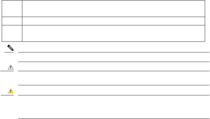
Figure 1: Cisco IW3702-2E-UXK9/IW3702-2E-x-K9 Bottom Panel View
1 |
Status LED |
6 |
Power(PWR)connector |
2 |
Antenna port B |
7 |
Console (CON) port |
3 |
PoE OUT port |
8 |
Antenna port A |
4 |
PoE IN port |
9 |
Ground connection |
5 |
Protective vent port / Reset button (covered) |
|
|
Note There are four antenna ports on the Cisco IW3702-2E-UXK9/IW3702-2E-x-K9 model: two on the top and two on the bottom.
5

Figure 2: Cisco IW3702-2E-UXK9/IW3702-2E-x-K9 Top Panel View
1 Antenna port 3 Antenna port
CA
2 Antenna port 4 Antenna port
DB
Note There are four antenna ports on the Cisco IW3702-4E-UXK9/IW3702-4E-x-K9 model: all four connectors are on the top side.
6
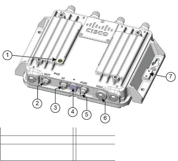
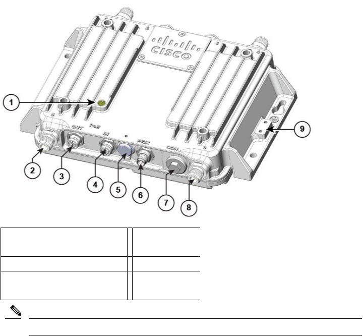
Figure 3: Cisco IW3702-4E-UXK9/IW3702-4E-x-K9 Bottom Panel View
1 |
Status LED |
5 |
Power(PWR)connector |
2 |
PoE OUT port |
6 |
Console (CON) port |
3 |
PoE IN port |
7 |
Ground connection |
4 |
Protective vent port / Reset button (covered) |
|
|
7
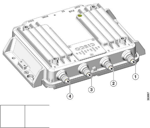
Figure 4: Cisco IW3702-4E-UXK9/IW3702-4E-x-K9 Top Panel View
1 Antenna port 3 Antenna port
CB
2 Antenna port 4 Antenna port
AD
Bottom Panel Components
This section describes the bottom panel components.
Status LED
The Status LEDs provide information on access point status, activity, and performance. The following table describes status LED states.
8

Table 2: Status LED |
|
|
Message Type |
LED Color |
System State |
Boot loader status |
Blinking pink |
DRAM memory test in progress. |
|
|
DRAM memory test OK. |
|
|
Board initialization in progress. |
|
|
Initializing flash file system. |
|
|
Flash memory test OK. |
|
|
Initializing Ethernet. |
|
|
Ethernet OK. |
|
|
Starting Cisco IOS. |
|
|
Initialization successful. |
Client association |
Green |
Normal operating condition but no wireless client association. |
status |
Blue |
Normal operating condition with at least one wireless client association. |
|
||
Operational status |
Blinking blue |
Software upgrade in progress. |
|
Cycling green-red-off |
Discovery/join process in progress. |
|
Rapidlycyclingblue-green-red |
Access point location command invoked. |
|
Blinking red |
Ethernet link not operational. |
Boot loader warnings |
Blinking blue |
Configuration recovery in progress (RESET button pushed for 30 seconds). |
|
Red |
Ethernet failure or image recovery (RESET button pushed for 50 seconds). |
|
Blinking pink |
Image recovery in progress (MODE button released). |
Boot loader errors |
Red |
DRAM memory test failure. |
|
Blinking red-blue |
FLASH file system failure. |
|
Blinking red-off |
Environment variable failure. |
|
|
Bad MAC address. |
|
|
Ethernet failure during image recovery. |
|
|
Boot environment failure. |
|
|
No Cisco image file. |
|
|
Boot failure. |
9
Message Type |
LED Color |
System State |
Cisco IOS errors
AP status when provisioned by Cisco AirProvision
Red
Cycling blue-green-red-off Cycling red-green-off Blinking white
Blinking teal (for 15 seconds) Blinking blue
Chirping red
Software failure. Disconnect and reconnect unit power. General warning. Insufficient inline power.
AP waiting to be primed.
AP priming via Cisco NDP in progress.
AP upon successful connection to Cisco AirProvision. AP priming via Cisco AirProvision in progress.
AP primed to wrong regulatory domain.
PWR Connectors
There are two options for powering the access point:
•DC input over the PWR connector.
•PoE inline power over the PoE IN port.
Note When powering the access point:
1.Power can be supplied via DC input (PWR connector) or PoE inline (PoE IN port), but not both.
2.We recommend that you not use two power options concurrently, but no harm results if both are present.
3.If using both power inputs, DC input (PWR connector) power takes precedence and PoE inline power is not used.
4.Power supply redundancy is not supported.
The access point requires a DC power supply. To power the access point with a DC power supply, you connect the DC power to the PWR connector on the bottom panel. The DC input voltage range is +12 to +48 VDC (-20%, +25%).
The PWR connector is an M12 A-code, 4-pin (male) connector. See Power Port, on page 75 and DC Input and PoE IN Specifications, on page 67.
PoE OUT Port
Note The PoE OUT port is only supported when the access point is powered over the PWR port. When powered over the PoE IN port, PoE OUT functionality is not supported.
The PoE OUT port is a 10/100/1000 BASE-T port with an M12 X-code connector. The PoE OUT port supplies PoE inline DC power to power external devices. The PoE OUT port pin-out conforms to Alternative A-MDIX mode.
10
Note PoE inline power supports IEEE 802.3af compliant devices and delivers up to 15.4 W of PoE.
For more information about the PoE OUT, PoE IN, and DC input, see DC Input and PoE IN Specifications, on page 67.
PoE IN Port
The PoE IN port is a 10/100/1000 BASE-T port with an M12 X-code connector. The port has auto-sensing and auto-MDIX capabilities.
Note The PoE IN port is an alternate power input to DC input over the PWR port.
•Power the access point over the PWR port to enable the PoE OUT port.
•When powered over the PoE IN port, PoE OUT functionality is not supported.
For more information, see DC Input and PoE IN Specifications, on page 67.
Protective Vent Port
The protective vent port relieves pressure inside the access point chassis possibly caused by changing temperatures in the installation environment. The vent prevents pressure from building up and damaging enclosure seals and potentially exposing sensitive components to water. The vent also protects the access point interior from dust, dirt, water, and other environmental elements.
Note If the vent is removed or damaged, the access point is subject to moisture damage.
Reset Button
You use the reset button for configuration or image recovery. The reset button is under the protective vent port. To access the reset button:
1.Use a 5/8" socket to remove the protective vent.
2.Disconnect power (the power jack for external power or the Ethernet cable for in-line power) from the access point.
3.Press and hold the RESET button while you reconnect power to the access point.
4.Press the reset button.
•Hold the RESET button until the Status LED turns blinking blue (usually, pushed for 30 seconds) to reset the access point to its factory settings.
•Hold the RESET button until the Status LED turns solid Red (usually, pushed for 50 seconds) to do image recovery.
5.Replace the protective vent using 5/8" socket.
6.Torque the protective vent to 5-7 inch-lbs.
11

Console Port
You can connect the access point to a PC or laptop through the RJ45 CON port. The RJ45 CON port uses the Cisco console port RJ45-to-DB9 cable (Cisco PN 72-3383-01).
A cable port seal covers the CON port. This liquid-tight plug protects the access point from environmental elements. Ensure that the plug is installed during normal operation or when unit is unattended. You can remove and install the port plug with a 1/2" (13 mm) socket. Torque it to 6-7 ft-lbs
For more information, see Console Port, on page 77.
Ground Stud
The ground stud is the access point ground. You use screws to attach the wired grounding lug to the ground stud. Connect the other end of the ground wire to an earth ground such as a grounding rod or appropriate ground point on a grounded pole.
Top Panel Components
This section describes the top panel components.
Antenna Port
The antenna connector is a type N female coaxial connector.
Hard Points
The hard points are alternate mounting or attachment points for additional equipment such as directional antennas or covers.
Note Do not attach third-party radios using these hard points.
12
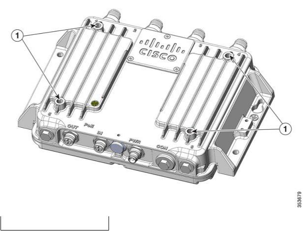
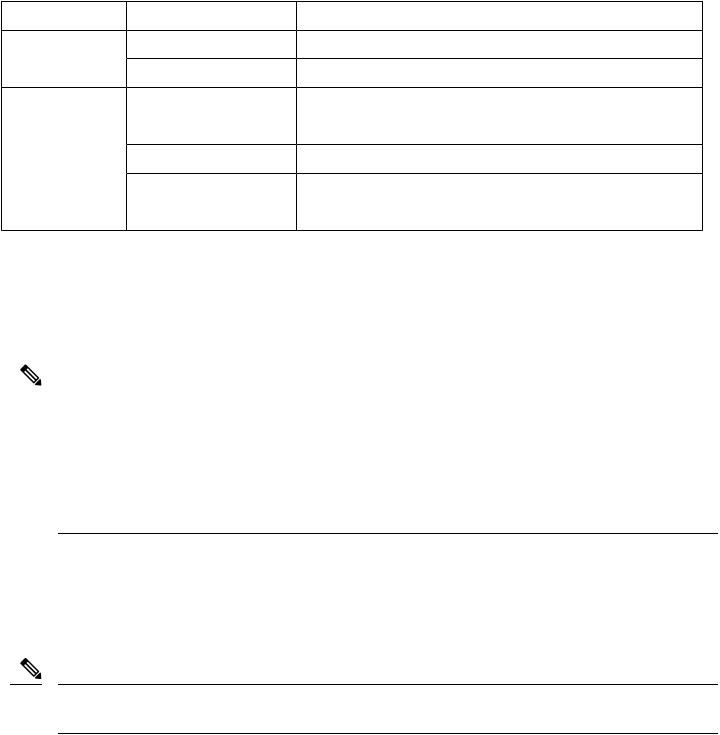
Figure 5: Cisco IW3702 Series Access Point Hard Points
1 Hard points 1/4-20UNC-2B, .45" deep
Management Options
You can manage the access point using the following options:
•Web browser Interface—Contains management pages to change the wireless device settings, upgrade firmware, and monitor and configure other wireless devices on the network.
•Cisco IOS command-line interface (CLI)—Configures the access point. You can access the CLI by directly connecting a PC to the console port, or you can access the CLI using a Telnet session from a remote management station.
Installation
You can install the access point on a wall, ceiling or pole, in a cabinet or rack, under a seat, or in a plenum airspace. You can direct mount, DIN rail mount, or attach the access point on a pole mounting bracket.
Perform the installation procedures in this order:
1.Preparing for Installation, on page 14
2.Unpacking the Components, on page 17
13

3.Mounting the Access Point, on page 19
4.Connecting the Protective Ground and Power, on page 19
5.Connecting the Antennas, on page 22
6.Connecting to Access Point Ports, on page 22
Preparing for Installation
The following topics prepare you for installing the unit:
Warnings
These warnings are translated into several languages in the Regulatory Compliance and Safety Information for the Cisco IW3702 Access Point on Cisco.com.
Danger Only trained and qualified personnel should be allowed to install, replace, or service this equipment. Statement 1030
Danger In order to comply with FCC radio frequency (RF) exposure limits, antennas for this product should be located a minimum of 7.9 in. (20 cm) or more from the body of all persons. Statement 332
Danger Read the installation instructions before you connect the system to its power source. Statement 1004
Danger This unit is intended for installation in restricted access areas. A restricted access area can be accessed only through the use of a special tool, lock and key, or other means of security. Statement 1017
Danger This equipment must be grounded. Never defeat the ground conductor or operate the equipment in the absence of a suitably installed ground conductor. Contact the appropriate electrical inspection authority or an electrician if you are uncertain that suitable grounding is available. Statement 1024
Danger Ultimate disposal of this product should be handled according to all national laws and regulations. Statement 1040
Danger To prevent the system from overheating, do not operate it in an area that exceeds the maximum recommended ambient temperature of: 70°C Statement 1047
14

Danger Installation of the equipment must comply with local and national electrical codes. Statement 1074
Danger This product relies on the building’s installation for short-circuit (overcurrent) protection. Ensure that the protective device is rated not greater than: 15 A. Statement 1005
Danger Do not operate your wireless network device near unshielded blasting caps or in an explosive environment unless the device has been modified to be especially qualified for such use. Statement 245B
Caution The fasteners you use to mount an access point on a ceiling must be capable of maintaining a minimum pullout force of 20 lbs (9 kg) and must use all 4 indented holes on the mounting bracket.
Note The access point is suitable for use in environmental air space in accordance with section 300.22.C of the National Electrical Code and sections 2-128, 12-010(3), and 12-100 of the Canadian Electrical Code, Part 1, C22.1. You should not install the power supply or power injector in air handling spaces.
Note Use only with listed ITE equipment.
EMC Environmental Conditions for Products Installed in the European Union
ThissectionappliestoproductsinstalledintheEuropeanUnion. Theequipmentisintendedtooperateunderthefollowingenvironmental conditions with respect to EMC:
•A separate defined location under the user’s control.
•Earthing and bonding meets the requirements of ETSI EN 300 253 or ITU-T K.27.
•AC-power distribution shall be one of the following types, where applicable: TN-S and TN-C as defined in IEC 60364-3.
In addition, if equipment is operated in a domestic environment, interference could occur.
National Restrictions within the European Union
Within the European Union as well as within the majority of the other European Countries, the 2.4 and 5 GHz bands are available for use by wireless LANs.
The following table provides an overview of the regulatory requirements that are generally applicable for 2.4 and 5 GHz bands.
The requirements for any country might evolve. We recommend that you check with your local authorities for the current status of regulations for 2.4 and 5 GHz wireless LANs within your country.
15

Table 3: Overview of Regulatory Requirements for Wireless LANs |
|
|
|
Frequency Band (MHz) |
Maximum Power Level Effective Isotropic Radiated Power (EIRP) |
Indoor |
Indoor and Outdoor |
|
mW |
only |
|
2400-2483.5 |
100 |
— |
x |
5150-5350 |
200 |
x |
— |
5470-5725 |
1000 |
— |
x |
Tools and Hardware Required
These tools and hardware are required for access point installation:
•Crimping tool (such as Thomas & Bett part number WT2000, ERG-2001, or equivalent)
•6-gauge copper ground wire
•Wire-stripping tools for stripping 6-gauge wire
•Number 2 Phillips screwdriver
•1/2" (13 mm) socket for port plug
•5/8" (16 mm) socket for protective vent
•5/32" (4 mm) hex key for mounting screws
•Torque wrench (both inch-lbs and ft-lbs)
Installation Guidelines
Because the access point is a radio device, it is susceptible to common causes of interference that can reduce throughput and range. Follow these guidelines to ensure the best possible performance:
•For information on planning and initially configuring your Cisco Mesh network, refer to the Cisco Wireless Mesh Access Points, Design and Deployment Guide.
•Review the FCC Guidelines for Installation and Operation of Outdoor Wireless LAN Devices (U-NII devices) Operating in the 5470-5725 MHz Band Data Sheet at: http://www.cisco.com/c/en/us/products/collateral/routers/3200-series-rugged-integrated-services-routers-isr/data_sheet_c78-647116.html
The above document provides guidelines to mitigate interference to Federal Aviation Administration (FAA) Terminal Doppler Weather Radar (TDWR) as well as details on registering your access point with the Wireless Internet Service Providers Association (WISPA).
•Perform a site survey before beginning the installation.
•Install the access point in an area where structures, trees, or hills do not obstruct radio signals to and from the devices.
•For information on priming a Cisco universal access point, see the Cisco Aironet Universal AP Priming and Cisco AirProvision User Guide at: http://www.cisco.com/c/en/us/td/docs/wireless/access_point/ux-ap/guide/uxap-mobapp-g.html
16

Site Surveys
Every network application is a unique installation. Before installing an access point, perform a site survey to determine the optimum use of networking components and maximize range, coverage, and network performance.
Consider the following operating and environmental conditions when performing a site survey:
•Data rates—Sensitivity and range are inversely proportional to data bit rates. The maximum radio range is achieved at the lowest workable data rate. A decrease in receiver sensitivity occurs as the radio data increases.
•Antenna type and placement—Proper antenna configuration is a critical factor in maximizing radio range. As a general rule, range increases in proportion to antenna height. However, do not place the antenna higher than necessary, because extra height increases potential interference from other unlicensed radio systems and decreases the wireless coverage from the ground.
•Physical environment—Clear or open areas provide better radio range than closed or filled areas.
•Obstructions—Physical obstructions such as buildings, trees, or hills can hinder performance of wireless devices. Avoid locating the devices in a location where an obstruction exists between the sending and receiving antennas.
Unpacking the Components
The typical access point package contains the following items:
•Access point
•Cisco product documentation and translated safety warnings
•Ground lug (Panduit PLCD6-10A-L), screws, and oxide inhibitor (contained in a tube)
•Console cable
•CoaxSeal—Coaxial cable/connector seal tape for N connectors
•Two M12 Ethernet connector caps (installed on the PoE OUT and PoE IN ports)
•One M12 power connector cap (installed on the PWR port)
Note The M12 connector caps are installed on the ports for protection when the AP is shipped. Remove the caps before using the ports. See the following figure for the locations of each port with M12 cap.
17

Figure 6: PoE and PWR Connectors With Caps
1 PoEportswithcaps 2 PWRconnectorwithcap
To unpack the access point:
Procedure
Step 1 Open the shipping container and carefully remove the contents.
Step 2 Return all packing materials to the shipping container, and save it.
Step 3 Ensure that all the access point package items are included in the shipment.
What to do next
Note If any item is damaged or missing, notify your sales representative.
18
Mounting the Access Point
For instructions about mounting the access point, see the Cisco IW3702 Access Point Mounting Guide
Connecting the Protective Ground and Power
Perform the following steps in order when connecting the access point to power and ground.
1.Grounding the Access Point, on page 19
2.Wiring the Access Point DC Power, on page 21
Grounding the Access Point
In all installations, after mounting the access point, you must properly ground the unit before connecting power cables.
Danger This equipment must be grounded. Never defeat the ground conductor or operate the equipment in the absence of a suitably installed ground conductor. Contact the appropriate electrical inspection authority or an electrician if you are uncertain that suitable grounding is available. Statement 1024
Danger Installation of the equipment must comply with local and national electrical codes. Statement 1074
The access point is shipped with a grounding kit.
Figure 7: Access Point Grounding Kit Contents
1 Grounding lug
2 Screwsx2,M4x6mm
Note The grounding kit also includes the oxide inhibitor, which is contained in a tube.
To ground the access point:
Procedure
19
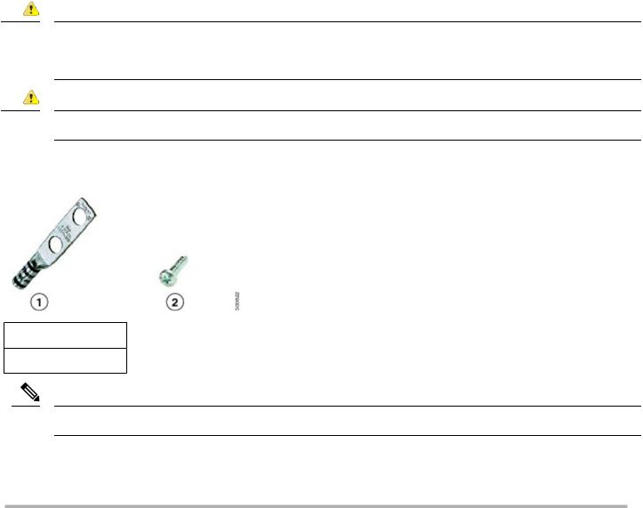
Step 1 Use a crimping tool to crimp a 6-AWG ground wire (not included in the grounding kit) to the ground lug.
Step 2 Connect the supplied ground lug to the access point ground connection point using the supplied screws. Apply supplied oxide inhibitor between the ground lug and the access point ground connection.
Step 3 Tighten the screws to 20-25 inch-lbs of torque.
1 Groundconnection
20
Step 4 If necessary, strip the other end of the ground wire and connect it to a reliable earth ground such as a grounding rod or appropriate ground point on a grounded pole. Length of the ground cable should not exceed 1 meter, and 0.5 meter is preferred. Use supplied oxide inhibitor on the grounded interface.
Wiring the Access Point DC Power
To wire the access point to a DC power source:
Procedure
Step 1 Verify that the access point is grounded (see Grounding the Access Point, on page 19).
Step 2 Connect the power lead to the PWR connector by turning the cable clockwise, as shown in the following figure.
1 Power cable and PWR connector
21

Step 3 Connect the other end of the power cable to the DC power source using the power source wiring instructions. The PWR connector pinout descriptions are in Power Port, on page 75.
Connecting the Antennas
Connect each antenna based on:
•Antenna arrangement, cabling, lightning arrestor, and adapter information in Examples of Access Point and Antenna Deployment Configurations, on page 26.
•Installation information in Antenna Types and Models, on page 24.
Connecting to Access Point Ports
This section describes connecting the access point to PoE.
Danger For connections outside the building where the equipment is installed, the following ports must be connected through an approved network termination unit with integral circuit protection.10/100/1000 Ethernet Statement 1044
Connecting to the PoE IN or PoE OUT Port
Procedure
Step 1 Use shielded cables with a M12 X-Code plug to connect to the PoE IN or PoE OUT ports.
Note Ethernet cables must have an internal shield around the signal wires. There must be a contiguous ground between the connector shell that interfaces with the IW3702 and the connector shell on the far end of the cable. Maximum cable length should not exceed 100 meters.
Step 2 Connect the PoE IN cable to the PoE IN port, or the PoE OUT cable to the PoE OUT port by turning the cable clockwise, as shown in the following figure.
22
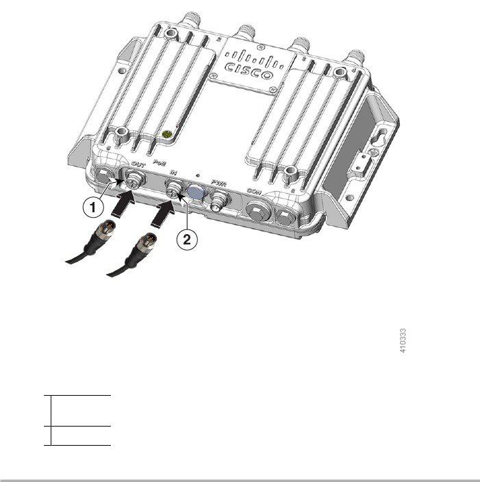
Figure 8: Connecting to the PoE IN or PoE OUT Ports
1 PoE OUT
cable
2 PoE IN cable
Note When powered over the PoE IN port, PoE OUT functionality is not supported.
Antennas and RF Accessories
This section describes antennas, RF Accessories, and their configuration for the access point.
23

Cisco recommends using a coax seal (such as CoaxSeal) for outdoor connections, to prevent moisture and other weathering elements from affecting performance. For more information on using coax seal on the N connector to cable or antenna interface, see the instructions on your antenna documents.
Antenna Types and Models
The antennas used in these configurations are:
•Cisco Aironet Dual-Band Omnidirectional Antenna (White model—Cisco PID AIR-ANT2547V-N) Cisco Aironet Dual-Band Omnidirectional Antenna (Cisco PID AIR-ANT2547VG-N)
These are the related models:
•White model (Cisco PID AIR-ANT2547V-N=)
•Grey Model (Cisco PID AIR-ANT2547VG-N=)
•Cisco Aironet Four-Port Dual-Band Polarization-Diverse Array Antenna (Cisco PID AIR-ANT2513P4M-N)
•Cisco Aironet Four-Element, MIMO, Dual-Band Ceiling Mount Omnidirectional Antenna (Cisco PID AIR-ANT2524V4C-R)
•Cisco Aironet Dual-Band MIMO Wall-Mounted Omnidirectional Antenna (Cisco PID AIR-ANT2544V4M-R)
•Cisco Aironet 2.4 GHz/5 GHz MIMO 4-Element Patch Antenna (Cisco PID AIR-ANT2566P4W-R)
•Cisco Aironet Dual-band Dipole Antenna (Cisco PID AIR-ANT2524DB-R, AIR-ANT2524DG-R, and AIR-ANT2524DW-R)
•Cisco Aironet 2.4-GHz 13-dBi Directional Antenna (Cisco PID AIR-ANT2413P2M-N)
•Cisco Aironet 5-GHz 13-dBi Directional Antenna (Cisco PID AIR-ANT5114P2M-N)
•Cisco Aironet 2.4 GHz/5 GHz Dual-Band Polarization-Diverse Directional Array Antenna (AIR-ANT2566D4M-R)
RF Accessories
This section contains the IW3702 RF accessories: cables, adapters, and lightning arrestors.
The following table defines the cables available for interconnecting the antennas and the access point.
Table 4: RF Cables |
|
|
|
Cisco PID |
Description2 |
Loss at 2.4 |
Loss at 5.8 |
|
|
GHz |
GHz |
N(m) to N(m) RF cables: |
|
|
|
AIR-CAB002L240-N N(m)-R/A to N(m)-STR, LMR-240 , 2ft RF cable |
0.5 dB |
0.8 dB |
|
|
Type: Indoor Interconnect. |
|
|
|
Not DB, CMR or CMP |
|
|
CAB-L400-5-N-N N(m)-R/A to N(m)-STR, LMR-400-DB , 5ft RF cable |
0.5 dB |
0.8 dB |
|
|
Type: outdoor DB (direct burial) |
|
|
24
Loading...