


 Loading...
REVIEW DRAFT—CISCO CONFIDENTIAL
Cisco Catalyst IW6300 Heavy Duty Series Access Point Hardware Installation Guide
November 2019
Americas Headquarters
Cisco Systems, Inc. 170 West Tasman Drive
San Jose, CA 95134-1706 USA http://www.cisco.com Tel: 408 526-4000
800 553-NETS (6387) Fax: 408 527-0883
THE SPECIFICATIONS AND INFORMATION REGARDING THE PRODUCTS IN THIS MANUAL ARE SUBJECT TO CHANGE WITHOUT NOTICE. ALL STATEMENTS, INFORMATION, AND RECOMMENDATIONS IN THIS MANUAL ARE BELIEVED TO BE ACCURATE BUT ARE PRESENTED WITHOUT WARRANTY OF ANY KIND, EXPRESS OR IMPLIED. USERS MUST TAKE FULL RESPONSIBILITY FOR THEIR APPLICATION OF ANY PRODUCTS.
THE SOFTWARE LICENSE AND LIMITED WARRANTY FOR THE ACCOMPANYING PRODUCT ARE SET FORTH IN THE INFORMATION PACKET THAT SHIPPED WITH THE PRODUCT AND ARE INCORPORATED HEREIN BY THIS REFERENCE. IF YOU ARE UNABLE TO LOCATE THE SOFTWARE LICENSE OR LIMITED WARRANTY, CONTACT YOUR CISCO REPRESENTATIVE FOR A COPY.
The following information is for FCC compliance of Class A devices: This equipment has been tested and found to comply with the limits for a Class A digital device, pursuant to part 15 of the FCC rules. These limits are designed to provide reasonable protection against harmful interference when the equipment is operated in a commercial environment. This equipment generates, uses, and can radiate radio-frequency energy and, if not installed and used in accordance with the instruction manual, may cause harmful interference to radio communications. Operation of this equipment in a residential area is likely to cause harmful interference, in which case users will be required to correct the interference at their own expense.
The following information is for FCC compliance of Class B devices: This equipment has been tested and found to comply with the limits for a Class B digital device, pursuant to part 15 of the FCC rules. These limits are designed to provide reasonable protection against harmful interference in a residential installation. This equipment generates, uses and can radiate radio frequency energy and, if not installed and used in accordance with the instructions, may cause harmful interference to radio communications.
However, there is no guarantee that interference will not occur in a particular installation. If the equipment causes interference to radio or television reception, which can be determined by turning the equipment off and on, users are encouraged to try to correct the interference by using one or more of the following measures:
•Reorient or relocate the receiving antenna.
•Increase the separation between the equipment and receiver.
•Connect the equipment into an outlet on a circuit different from that to which the receiver is connected.
•Consult the dealer or an experienced radio/TV technician for help.
Modifications to this product not authorized by Cisco could void the FCC approval and negate your authority to operate the product.
The Cisco implementation of TCP header compression is an adaptation of a program developed by the University of California, Berkeley (UCB) as part of UCB’s public domain version of the UNIX operating system. All rights reserved. Copyright © 1981, Regents of the University of California.
NOTWITHSTANDING ANY OTHER WARRANTY HEREIN, ALL DOCUMENT FILES AND SOFTWARE OF THESE SUPPLIERS ARE PROVIDED “AS IS” WITH ALL FAULTS. CISCO AND THE ABOVE-NAMED SUPPLIERS DISCLAIM ALL WARRANTIES, EXPRESSED OR IMPLIED, INCLUDING, WITHOUT LIMITATION, THOSE OF MERCHANTABILITY, FITNESS FOR A PARTICULAR PURPOSE AND NONINFRINGEMENT OR ARISING FROM A COURSE OF DEALING, USAGE, OR TRADE PRACTICE.
IN NO EVENT SHALL CISCO OR ITS SUPPLIERS BE LIABLE FOR ANY INDIRECT, SPECIAL, CONSEQUENTIAL, OR INCIDENTAL DAMAGES, INCLUDING, WITHOUT LIMITATION, LOST PROFITS OR LOSS OR DAMAGE TO DATA ARISING OUT OF THE USE OR INABILITY TO USE THIS MANUAL, EVEN IF CISCO OR ITS SUPPLIERS HAVE BEEN ADVISED OF THE POSSIBILITY OF SUCH DAMAGES.
CCDE, CCENT, Cisco Eos, Cisco HealthPresence, the Cisco logo, Cisco Lumin, Cisco Nexus, Cisco StadiumVision, Cisco TelePresence, Cisco WebEx, DCE, and Welcome to the Human Network are trademarks; Changing the Way We Work, Live, Play, and Learn and Cisco Store are service marks; and Access Registrar, Aironet, AsyncOS, Bringing the Meeting To You, Catalyst, CCDA, CCDP, CCIE, CCIP, CCNA, CCNP, CCSP, CCVP, Cisco, the Cisco Certified Internetwork Expert logo, Cisco IOS, Cisco Press, Cisco Systems, Cisco Systems Capital, the Cisco Systems logo, Cisco Unity, Collaboration Without Limitation, EtherFast, EtherSwitch, Event Center, Fast Step, Follow Me Browsing, FormShare, GigaDrive, HomeLink, Internet Quotient, IOS, iPhone, iQuick Study, IronPort, the IronPort logo, LightStream, Linksys, MediaTone, MeetingPlace, MeetingPlace Chime Sound, MGX, Networkers, Networking Academy, Network Registrar, PCNow, PIX, PowerPanels, ProConnect, ScriptShare, SenderBase, SMARTnet, Spectrum Expert, StackWise, The Fastest Way to Increase Your Internet Quotient, TransPath, WebEx, and the WebEx logo are registered trademarks of Cisco Systems, Inc. and/or its affiliates in the United States and certain other countries.
All other trademarks mentioned in this document or website are the property of their respective owners. The use of the word partner does not imply a partnership relationship between Cisco and any other company. (0812R)
Any Internet Protocol (IP) addresses and phone numbers used in this document are not intended to be actual addresses and phone numbers. Any examples, command display output, network topology diagrams, and other figures included in the document are shown for illustrative purposes only. Any use of actual IP addresses or phone numbers in illustrative content is unintentional and coincidental.
Cisco Catalyst IW6300 Heavy Duty Series Access Point Hardware Installation Guide
© 2019 Cisco Systems, Inc. All rights reserved.

C O N T E N T S
|
Preface |
1 |
|
|
|
Objectives |
1 |
|
|
|
Audience |
1 |
|
|
|
Conventions |
1 |
|
|
|
Related Documents |
2 |
||
|
Finding the Product Serial Number 3 |
|||
|
Overview |
|
|
|
C H A P T E R 1 |
1-1 |
|
|
|
|
About the Access Point 1-1 |
|||
|
Hardware Models |
1-2 |
||
|
Hardware Features |
1-4 |
||
Connectors 1-4 |
|
|
IW-6300H Access Point Internal Connectors 1-4 |
||
Console Port and Reset Button 1-5 |
||
Power Connector |
1-5 |
|
Antenna Ports |
1-7 |
|
Power Sources |
1-8 |
|
Power Injectors |
1-8 |
|
Ethernet (PoE) Ports |
1-9 |
|
Fiber Option |
1-9 |
|
|
1/2-NPT I/O Ports |
1-9 |
|
|
|
Optional Hardware |
1-11 |
|
|
|
Before You Begin 2-1 |
|
|
|
C H A P T E R 2 |
|
|
|
|
|
Unpacking the Access Point 2-1 |
|
||
|
Package Contents |
2-1 |
|
|
|
Tools and Hardware |
2-2 |
|
|
|
Optional Tools and Hardware 2-2 |
|
||
|
Optional Tools and Hardware That You Supply 2-2 |
|||
|
Pole Installation Hardware and Tools |
2-3 |
||
|
Warnings 2-3 |
|
|
|
|
Safety Information |
2-3 |
|
|
|
FCC Safety Compliance Statement |
2-4 |
||
|
Safety Precautions |
2-4 |
|
|
Cisco Industrial Wireless 6300 Series Access Point Hardware Installation Guide
1

Contents
|
|
Avoiding Damage to Radios in a Testing Environment |
2-5 |
||||||
|
|
Safety Precautions When Installing Antennas |
2-6 |
|
|||||
|
|
Installation Guidelines |
2-7 |
|
|
|
|
|
|
|
|
Site Surveys 2-7 |
|
|
|
|
|
|
|
|
|
Before Beginning the Installation 2-8 |
|
|
|||||
|
|
Installing the Access Points |
|
|
|
|
|
||
C H A P T E R |
3 |
3-1 |
|
|
|
|
|||
|
|
Mounting on a Wall or a Pole |
3-1 |
|
|
|
|||
|
|
Installation Option |
3-1 |
|
|
|
|
|
|
|
|
Access Point Mounting Orientation |
3-2 |
|
|
||||
|
|
Mounting the Access Point on a Wall 3-3 |
|
|
|||||
|
|
Mounting the Access Point on a Pole |
3-6 |
|
|
||||
|
|
Assembling the Pole Clamp Bracket and the Mounting Bracket 3-6 |
|||||||
|
|
Pole Mounting |
3-8 |
|
|
|
|
|
|
|
|
Working with the Access Cover |
3-14 |
|
|
|
|||
|
|
Opening the Access Cover |
3-14 |
|
|
|
|||
|
|
Closing the Access Cover |
|
3-15 |
|
|
|
||
|
|
Installing External Antennas |
3-15 |
|
|
|
|||
|
|
Non-Cisco Antennas |
3-16 |
|
|
|
|
||
|
|
Grounding the Access Point |
3-16 |
|
|
|
|||
|
|
Using the Reset Button |
3-18 |
|
|
|
|
|
|
|
|
Powering the Access Point 3-18 |
|
|
|
||||
|
|
Connecting a Power Injector |
3-19 |
|
|
|
|||
|
|
Connecting an Ethernet Cable to the Access Point |
3-20 |
||||||
|
|
Connecting AC Power to IW-6300H-AC-X-K9 |
3-21 |
|
|||||
|
|
Connecting DC Power to IW-6300H-DCW-X-K9 |
3-22 |
||||||
|
|
Connecting DC Power to IW-6300H-DC-X-K9 |
3-23 |
|
|||||
|
|
Performing Maintenance |
3-25 |
|
|
|
|
||
|
|
Removing the Access Point from Service |
3-25 |
||||||
|
|
Conducting Periodic Inspections |
3-25 |
|
|
||||
|
|
Conducting Periodic Cleaning |
3-25 |
|
|
||||
|
|
What to Do Next 3-25 |
|
|
|
|
|
||
|
|
Troubleshooting |
|
|
|
|
|
|
|
C H A P T E R |
4 |
4-1 |
|
|
|
|
|
|
|
|
|
Guidelines for Using the Access Points |
4-1 |
|
|
||||
|
|
Important Notes |
4-2 |
|
|
|
|
|
|
|
|
Convergence Delays |
4-2 |
|
|
|
|
||
|
|
Bridge Loop |
4-2 |
|
|
|
|
|
|
Cisco Industrial Wireless 6300 Series Access Point Hardware Installation Guide
2

Contents
|
Controller DHCP Server |
4-2 |
|
|
|
||||
|
MAP Data Traffic |
4-3 |
|
|
|
|
|||
|
Controller MAC Filter List |
4-3 |
|
|
|
||||
|
Accessing the Console Port and the Reset Button 4-3 |
|
|||||||
|
Resetting the Access Point |
4-4 |
|
|
|||||
|
Monitoring the Access Point LEDs |
4-4 |
|
|
|||||
|
Verifying Controller Association |
4-6 |
|
|
|||||
|
Changing the Bridge Group Name |
4-7 |
|
|
|||||
|
Declarations of Conformity and Regulatory Information A-1 |
|
|||||||
A P P E N D I X A |
|
||||||||
|
Manufacturers Federal Communication Commission Declaration of Conformity Statement A-2 |
||||||||
|
Industry Canada |
A-3 |
|
|
|
|
|
|
|
|
Canadian Compliance Statement A-3 |
|
|
||||||
|
Declaration of Conformity for RF Exposure |
A-3 |
|
||||||
|
European Community, Switzerland, Norway, Iceland, and Liechtenstein A-4 |
||||||||
|
Declaration of Conformity with regard to the R&TTE Directive 1999/5/EC & Medical Directive |
||||||||
|
93/42/EEC |
A-4 |
|
|
|
|
|
|
|
|
Declaration of Conformity for RF Exposure |
A-5 |
|
||||||
|
United States |
A-5 |
|
|
|
|
|
||
|
Canada |
A-5 |
|
|
|
|
|
|
|
|
European Union |
A-5 |
|
|
|
|
|
||
|
Australia |
A-5 |
|
|
|
|
|
|
|
|
Guidelines for Operating Cisco Aironet Access Points in Japan |
A-6 |
|||||||
|
Japanese Translation |
A-6 |
|
|
|
||||
|
English Translation |
A-6 |
|
|
|
|
|||
|
Japanese Translation |
A-7 |
|
|
|
||||
|
English Translation |
A-7 |
|
|
|
|
|||
|
VCCI Statement for Japan |
A-7 |
|
|
|||||
|
Administrative Rules for Cisco Aironet Access Points in Taiwan |
A-8 |
|||||||
|
Chinese Translation |
A-8 |
|
|
|
|
|||
|
English Translation |
A-9 |
|
|
|
|
|||
|
Chinese Translation |
A-9 |
|
|
|
|
|||
|
English Translation |
A-9 |
|
|
|
|
|||
Taiwan NCC Statement |
A-10 |
English Translation |
A-10 |
Chinese Translation |
A-10 |
English Translation |
A-10 |
Chinese Translation |
A-10 |
Cisco Industrial Wireless 6300 Series Access Point Hardware Installation Guide
3

Contents
|
|
EU Declaration of Conformity A-10 |
|
|
Access Point Specifications B-1 |
A P P E N D I X |
B |
|
|
|
Access Point Pinouts C-1 |
A P P E N D I X |
C |
Cisco Industrial Wireless 6300 Series Access Point Hardware Installation Guide
4

REVIEW DRAFT —CISCO CONFIDENTIAL
Preface
This section describes the objectives, audience, organization, and conventions of the Cisco Catalyst IW6300 Heavy Duty Series Access Point Hardware Installation Guide.
Objectives
This publication explains the steps for installing the Cisco Catalyst IW6300 Heavy Duty Series Access Point (called the access point or AP in this document).
Audience
This publication is for the person installing and configuring an access point for the first time. The installer should be familiar with network structures, terms, and concepts.
For installations in a hazardous locations environment, please refer to Getting Started and Product Document of Compliance for the Cisco Catalyst IW6300 Heavy Duty Series Access Points for additional installation information.
Warning Only trained and qualified personnel should be allowed to install, replace, or service this equipment.
Statement 1030
Conventions
This publication uses the following conventions:
Convention |
Description |
|
|
boldface font |
Commands, command options, and keywords are in boldface. |
|
|
italic font |
Arguments for which you supply values are in italics. |
|
|
[ ] |
Elements in square brackets are optional. |
|
|
screen font |
Terminal sessions and information the system displays are in |
|
screen font. |
|
|
boldface screen font |
Information you must enter is in boldface screen font. |
|
|
Cisco Catalyst IW6300 Heavy Duty Series Access Point Hardware Installation Guide
1

REVIEW DRAFT—CISCO CONFIDENTIAL
Convention |
Description |
|
|
italic screen font |
Arguments for which you supply values are in italic screen font. |
|
|
^ |
The symbol ^ represents the key labeled Control. For example, the |
|
key combination ^D in a screen display means hold down the |
|
Control key while you press the D key. |
|
|
< > |
Nonprinting characters, such as passwords, are in angle brackets. |
|
|
Notes use the following conventions:
Note Means reader take note. Notes contain helpful suggestions or references to materials not contained in this manual.
Cautions use the following conventions:
Caution Means reader be careful. In this situation, you might do something that could result in equipment damage or loss of data.
Warnings use the following conventions:
Warning IMPORTANT SAFETY INSTRUCTIONS
This warning symbol means danger. You are in a situation that could cause bodily injury. Before you work on any equipment, be aware of the hazards involved with electrical circuitry and be familiar with standard practices for preventing accidents. Use the statement number provided at the end of each warning to locate its translation in the translated safety warnings that accompanied this device. Statement 1071
SAVE THESE INSTRUCTIONS
Related Documents
To view all support information for the Cisco Catalyst IW6300 Heavy Duty Series Access Point, see:
https://www.cisco.com/c/en/us/products/wireless/industrial-wireless/index.html
In addition to the documentation available on the support page, you will need to refer to the following guides:
•Cisco Wireless LAN Controller Configuration Guide
http://www.cisco.com/c/en/us/support/wireless/wireless-lan-controller-software/products-installati on-and-configuration-guides-list.html
•Release Notes for Cisco Wireless LAN Controllers and Lightweight Access Points
http://www.cisco.com/c/en/us/support/wireless/wireless-lan-controller-software/products-release-n otes-list.html
•Cisco Mobility Express Configuration and User Guide
Cisco Catalyst IW6300 Heavy Duty Series Access Point Hardware Installation Guide
2

REVIEW DRAFT —CISCO CONFIDENTIAL
http://www.cisco.com/c/en/us/support/wireless/mobility-express/products-installation-and-configu ration-guides-list.html
• DHCP OPTION 43 for Lightweight Cisco Aironet Access Points Configuration Example
http://www.cisco.com/c/en/us/support/docs/wireless-mobility/wireless-lan-wlan/97066-dhcp-optio n-43-00.html
Click this link to browse to the Cisco Wireless documentation home page:
http://www.cisco.com/en/US/products/hw/wireless/index.html
To browse to the access point documentation, click Cisco Catalyst IW6300 Heavy Duty Series Access Point listed under “Outdoor and Industrial Wireless.” The documentation can be accessed from the Support box.
To browse to the Cisco Wireless LAN Controller documentation, click Standalone Controllers listed under “Wireless LAN Controllers.” The documentation can be accessed from the Support box.
Finding the Product Serial Number
The access point serial number is on the side of the access point.
The access point serial number label contains the following information:
•Serial number, such as WCN0636279B (11 alphanumeric digits).
•Access point MAC address, for example 68BDABF54600 (12 hexadecimal digits). It is located under the serial number.
You need your product serial number when requesting support from the Cisco Technical Assistance Center.
Cisco Catalyst IW6300 Heavy Duty Series Access Point Hardware Installation Guide
3

REVIEW DRAFT—CISCO CONFIDENTIAL
Cisco Catalyst IW6300 Heavy Duty Series Access Point Hardware Installation Guide
4
REVIEW DRAFT —CISCO CONFIDENTIAL
C H A P T E R 1
Overview
The Cisco Catalyst IW6300 Heavy Duty Series Access Point (hereafter called the access point or AP) is a wireless outdoor access point which is designed for use in a variety of network configurations. The access point supports wireless client access, bridging, and mesh wireless connectivity.
About the Access Point
The detailed up-to-date technical specifications for the Cisco Catalyst IW6300 Heavy Duty Series Access Points are available in the Cisco Catalyst IW6300 Heavy Duty Series Access Point Data Sheet at: https://www.cisco.com/c/en/us/products/collateral/wireless/industrial-wireless-6300-series/datasheet-c 78-742907.html
The Cisco Catalyst IW6300 Heavy Duty Series Access Point supports two radios (2.4-GHz and 5-GHz) and provides client access using the unlicensed RF Wi-Fi spectrum. Each model is equiped with four external Antenna ports, four Ethernet ports (one POE-In port, one SFP port, and two PoE-Out ports), and one USB2.0/3.0 port to support add-on module.
The 5 GHz radios have 802.11ac Wave 2 capability. The 2.4 GHz or 5 GHz radio can be used for client access or can be used for both client access and backhaul traffic.
The IW-6300 access point is a standalone unit that can be wall or pole mounted. The access point can operate as a relay node for other access points not directly connected to a wired network. Intelligent wireless routing is provided by the patented Adaptive Wireless Path Protocol (AWPP). This enables each access point to identify its neighbors and intelligently choose the optimal path to the wired network by calculating the cost of each path in terms of signal strength and the number of hops required to get to a controller.
The access point can be configured, monitored, and operated through a Cisco wireless LAN controller (hereafter called a controller) as described in the Cisco Wireless LAN Controller Configuration Guide. The Cisco Wireless Mesh Access Points, Design and Deployment Guide, describes how to plan and initially configure the Cisco mesh network, which supports wireless point-to-point, point-to-multipoint, and mesh deployments.
The controllers use a browser-based management system, a command-line interface (CLI), or the Cisco Prime Infrastructure (PI) network management system to manage the controller and the associated access points. The access point supports hardware-based advanced encryption standard (AES) encryption between wireless nodes to provide end-to-end security.
Cisco Catalyst IW6300 Heavy Duty Series Access Point Hardware Installation Guide
1-1
Chapter 1 Overview
Hardware Models
REVIEW DRAFT—CISCO CONFIDENTIAL
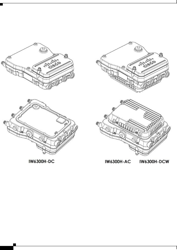
Hardware Models
Figure 1-1 IW-6300H Access Points
Cisco Catalyst IW6300 Heavy Duty Series Access Point Hardware Installation Guide
1-2

Chapter 1 Overview
Hardware Models
REVIEW DRAFT —CISCO CONFIDENTIAL
The model numbers (or part numbers) and configuration for the Cisco Catalyst IW6300 Heavy Duty Series Access Points are described in the following table.
Table 1-1 Access Point Model Numbers and Descriptions
Model (or part number)1 Configuration
IW-6300H-AC-X-K9 IP66 and IP67 rated, hazardous location certified, AC power version. This model has 4 external antenna ports and contains a 2.4 GHz and 5 GHz radio with an option to configure in centralized, Flexconnect, or mesh mode and supports AC power source.
IW-6300H-DCW-X-K9 IP66 and IP67 rated, hazardous location certified, DC wide range power version.
This model has 4 external antenna ports and contains a 2.4 GHz and 5 GHz radio with an option to configure in centralized, Flexconnect, or mesh mode, and supports 10.8 VDC to 36 VDC power source.
Note The marked DC input range is an absolute range. Do not apply tolerances.
IW-6300H-DC-X-K9 IP66 and IP67 rated, hazardous location certified, DC power version. This model has 4 external antenna ports and contains a 2.4 GHz and 5 GHz radio with an option to configure in centralized, Flexconnect, or mesh mode and supports 44VDC to 57 VDC power source.
Note The marked DC input range is an absolute range. Do not apply tolerances.
1. The “-X” in the model number represents a regulatory domain for a specific country.
A detailed list of components supported by each access point model is shown in the following table.
|
Table 1-2 |
Components of Each Access Point Model |
|
|
||||
|
|
|
|
|
|
|
|
|
|
|
|
|
|
|
PoE Out Port 1 |
Customer |
|
Product/PID |
|
Antenna Ports |
|
Ethernet Ports |
I/O Ports |
Power Option |
||
IW-6300H-AC-X-K9 |
|
Four Type N |
|
• |
One 100/1000Mbps SFP |
35.3W |
Four 1/2” |
UPoE, PoE+, AC |
|
|
Connectors |
|
|
for WAN |
|
NPT Ports |
(100V to 240V) |
|
|
|
|
|
|
|
|
|
IW-6300H-DCW-X- |
|
|
|
• |
One 100/1000Mbps RJ45 |
|
|
UPoE, PoE+, DC |
K9 |
|
|
|
|
for WAN (UPoE or PoE+ |
|
|
(10.8V to 36V) |
|
|
|
|
|
in) |
|
|
|
IW-6300H-DC-X-K9 |
|
|
|
|
|
|
UPoE, PoE+, DC |
|
|
|
|
|
|
|
|
||
|
|
|
|
• |
Two 100/1000Mbps RJ45 |
|
|
(44V to 57V)2 |
|
|
|
|
|
for LAN (802.11at or |
|
|
|
|
|
|
|
|
802.3af out) |
|
|
|
|
|
|
|
|
|
|
|
|
1.When powered with PoE+, the PoE Out power is not available, The PoE-Out port data link can still be active.
2.For DC SKU, if you want to output 802.3at type 2 PoE out power, DC input must >=51V. If you want to output 802.3af (802.3at type 1) PoE out power, DC input must >=45V.
For a detailed description of the declarations of conformity and regulatory information for the Cisco Catalyst IW6300 Heavy Duty Series Access Points, see Appendix A, “Declarations of Conformity and Regulatory Information.”
Cisco Catalyst IW6300 Heavy Duty Series Access Point Hardware Installation Guide
1-3
Chapter 1 Overview
Hardware Features
REVIEW DRAFT—CISCO CONFIDENTIAL
Hardware Features
This section describes the hardware features of the IW-6300H series access points.
Connectors
This section describes the access point connectors.
Note The illustrations in this document show all available connections for the access point. Unused connections are capped with a connector plug to ensure the dust/watertight integrity of the access point. See Working with the Access Cover for further details.
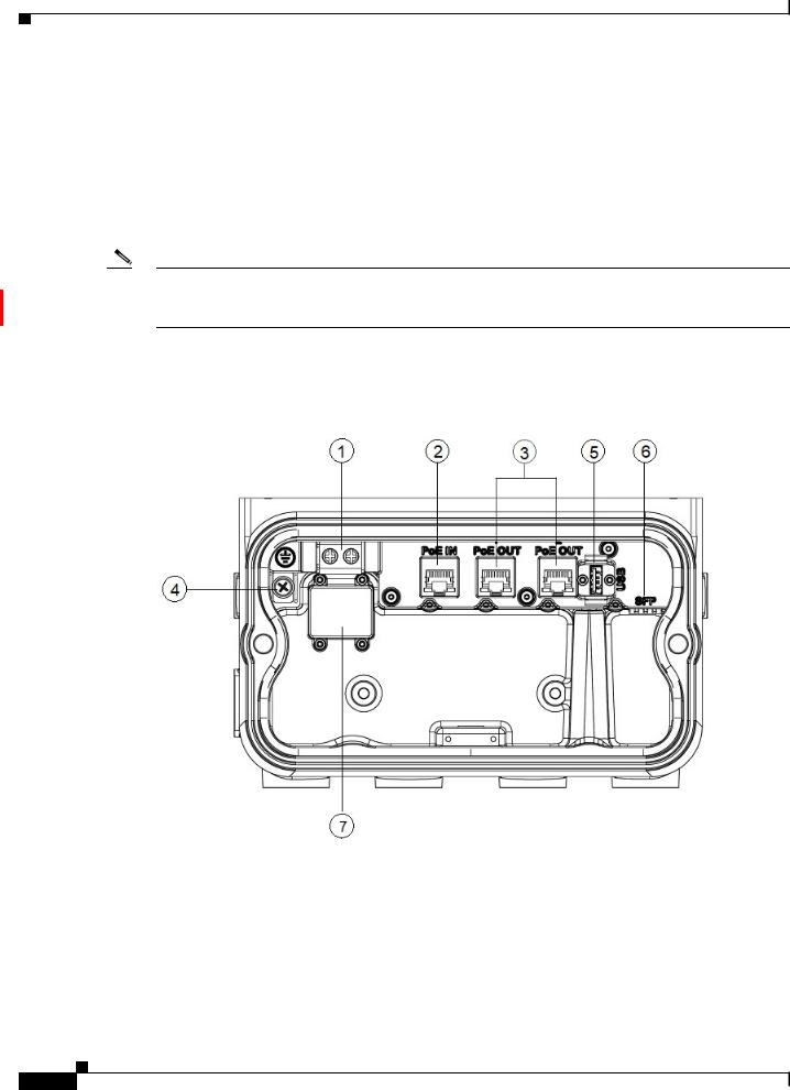
IW-6300H Access Point Internal Connectors
Figure 1-2 IW-6300H Access Point Internal Connectors
1 |
Power-IN (IW-6300H-DC-X-K9) |
5 |
USB port |
|
|
|
|
2 |
PoE In port |
6 |
SFP port |
|
|
|
|
3 |
PoE Out port |
7 |
Terminal block location of |
|
|
|
IW-6300H-AC-X-K9 and |
4 |
Internal ground |
|
|
|
IW-6300H-DCW-X-K9 |
||
|
|
|
|
|
|
|
|
Cisco Catalyst IW6300 Heavy Duty Series Access Point Hardware Installation Guide
1-4
Chapter 1 Overview
Hardware Features
REVIEW DRAFT —CISCO CONFIDENTIAL
Console Port and Reset Button
The console port and reset button are under a covering M25 plug located on the side of the access point, as shown in the following figure.
Figure 1-3 IW-6300H Access Point Console Port and Reset Button
1 |
Console port |
2 |
Reset button |
|
|
|
|
Inspect the seal of the plug and properly tighten it at the time of installation, and also every time the plug is removed and replaced. Tighten the plug to 5-6 lb-ft. If you do not tighten the plug properly, it will not meet IP66/67 criteria, and may lead to water leaking into the unit.
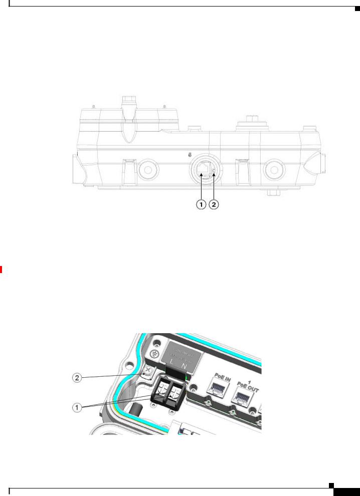
Power Connector
The following figure shows the AC power connector of access point model IW-6300-AC-X-K9.
Figure 1-4 AC Power Connector of Access Point Model IW-6300H-AC-X–K9
1 |
AC Power-IN |
2 |
Internal ground |
|
|
|
|
Cisco Catalyst IW6300 Heavy Duty Series Access Point Hardware Installation Guide
1-5
Chapter 1 Overview
Hardware Features
REVIEW DRAFT—CISCO CONFIDENTIAL
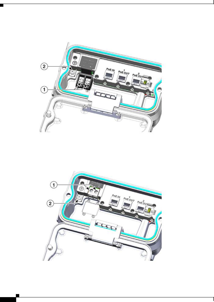
The following figure shows the DC power connector of access point model IW-6300-DCW-X-K9.
Figure 1-5 IW-6300H-DCW-X–K9 Power Connector
1 |
DC Power-IN |
2 |
Internal ground |
|
|
|
|
The following figure shows the DC power connector of access point model IW-6300-DC-X-K9.
Figure 1-6 IW-6300H-DC-X–K9 Power Connector
1 |
DC Power-IN |
2 |
Internal ground |
|
|
|
|
Cisco Catalyst IW6300 Heavy Duty Series Access Point Hardware Installation Guide
1-6
Chapter 1 Overview
Hardware Features
REVIEW DRAFT —CISCO CONFIDENTIAL
Antenna Ports
The access point antenna N-type connectors are located on the top of each model (see the following figure). The supported antennas can be directly attached to the access point or remotely located. When used in a Class 1, Zone 2, Division 2 hazardous location, this equipment must be mounted with proper RF cables (if required) and electrical wiring methods that comply with the governing electrical codes.
Note Antenna caps must be installed when an antenna is not in use (maximum torque range: 6.2-9.7 in-lbs).
Figure 1-7 Antenna Ports of IW-6300H Access Points
1 |
Antenna port B - Type N connector Wi-Fi |
3 |
Antenna port D - Type N connector Wi-Fi 5 GHz |
|
2.4/5 GHz TX/RX |
|
TX/RX |
|
|
|
|
2 |
Antenna port C - Type N connector Wi-Fi 5 |
4 |
Antenna port A - Type N connector Wi-Fi 2.4/5 |
|
GHz TX/RX |
|
GHz TX/RX |
|
|
|
|
The IW-6300H access point can be configured via software to support dual band or single band antennas. When configured for dual band antennas, antenna ports A and B are used to support multiple input/output (MIMO) operation on both 2.4 and 5 GHz radios. When using Cisco Aironet omnidirectional antennas with Type N male connectors, the antennas can be connected directly to the access point. If the antennas are remotely located, an appropriate low loss RF cable should be used.
Note Ensure that the antenna band mode is configured before the access point is installed.
When configured for single band antennas, antenna ports A and B support MIMO operation on the 2.4 GHz radio and antenna ports C and D support MIMO operation on the 5 GHz radio. See the Cisco Wireless LAN Controller Configuration Guide for information on the software configuration.
Cisco Catalyst IW6300 Heavy Duty Series Access Point Hardware Installation Guide
1-7

Chapter 1 Overview
Hardware Features
REVIEW DRAFT—CISCO CONFIDENTIAL
Use of four omnidirectional antennas attached directly to the Type N connectors is not recommended. To provide omnidirectional coverage with both 2.4 and 5 GHz radios using directly attached antennas, it is recommended to configure the IW-6300H in dual band mode, connect two dual band antennas such as AIR-ANT2547V-N, AIR-ANT2547V-N-HZ, or AIR-ANT2568VG-N to ports A and B, and cap ports C and D.
The 2 GHz b/g/n radio operates in 2.4 GHz ISM band. It supports channels 1-11 in the US, 1-13 in Europe, and 1-13 in Japan. It has 2 transmitters with a maximum total output power of 27 dBm for 802.11b/g/n operation. Output power is configurable for 8 levels in 3 dB steps. It has two receivers that enable maximum-ratio combining (MRC).
The 5 GHz a/n radio operates in the UNII-1 band (5.15-5.25 GHz), UNII-2 band (5.25 - 5.35 GHz), UNII-2 Extended/ETSI band (5.47 - 5.725 GHz), and the upper ISM band (5.725 - 5.850 GHz). It has two transmitters with a maximum total output power of 27 dBm depending on the regulatory domain. Tx power settings will change depending on the regulatory domain. Output power is configurable in 3 dB steps. Its two receivers enable maximum-ratio combining (MRC).
Power Sources
The Cisco Catalyst IW6300 Heavy Duty Series Access Points support the following power options:
1.Power over Ethernet by power injector AIR-PWRINJ-60RGD1= and AIR-PWRINJ-60RGD2=
2.AC or DC power
IW-6300H-AC-X-K9
85-264V~ maximum, marked 100-240V~, 50-60Hz, 1.3A
IW-6300H-DC-X–K9
44 to 57Vdc, 1.2A
IW-6300H-DCW-X-K9
10.8 to 36Vdc, 5.9A
Note The marked DC input range is an absolute range. Do not apply tolerances.
Warning To reduce risk of electric shock, connect the unit only to DC power source that complies with the Safety Extra-Low Voltage (SELV) requirements in IEC 60950 based safety standards or ES1 requirements in IEC 62368 based safety standards. Statement 1033
Power Injectors
The IW6300 series access points support the following power injectors:
•AIR-PWRINJ-60RGD1=
•AIR-PWRINJ-60RGD2=
Caution Power injector AIR-PWRINJ-60RGD is not certified for installation within hazardous locations environments.
Cisco Catalyst IW6300 Heavy Duty Series Access Point Hardware Installation Guide
1-8

Chapter 1 Overview
Hardware Features
REVIEW DRAFT —CISCO CONFIDENTIAL
For more information about installing the AIR-PWRINJ-60RGDx= power injectors, see Cisco Aironet Series Power Injectors AIR-PWRINJ-60RGD1= and AIR-PWRINJ-60RGD2= Installation Instructions.
Ethernet (PoE) Ports
The access point supports two Ethernet uplink port (one PoE-In port and one SPF fiber port), and two PoE-Out ports. The access point Ethernet uplink port uses an RJ-45 connector (with weatherproofing) to link the access point to the 10BASE-T, 100BASE-T, or 1000BASE-T network. The Ethernet cable is used to send and receive Ethernet data and to optionally supply inline power from the power injector or a suitably powered switch port.
Tip The access point senses the Ethernet and power signals and automatically switches internal circuitry to match the cable connections.
The Ethernet cable must be a shielded outdoor rated Category 5e (CAT5e) or better cable. The access point senses the Ethernet and power signals and automatically switches internal circuitry to match the cable connections.
Fiber Option
Warning Class 1 laser product. Statement 1008
The factory-orderable fiber option provides a fiber input and output capability. Fiber data is transmitted and received over a single or dual-strand fiber cable, depending on the SFP, which is connected to the access point using these SFP modules:
•1000BASE-LX single-mode rugged SFP (GLC-LX-SM-RGD=)
•1000BASE-SX multi-mode rugged SFP (GLC-SX-MM-RGD=)
•100BaseBX10-U rugged SFP (GLC-FE-100BX-URGD=)
•100BASE-FX rugged SFP (GLC-FE-100FX-RGD=)
•100BASE-LX10 rugged SFP (GLC-FE-100LX-RGD=)
•1000BASE-T rugged SFP (GLC-T-RGD=)
Note SFP modules are not hot-swappable. Plug and unplug the SFP module, the AP will reboot.
Client data is passed to the network controller through the fiber connection via a fiber-capable switch or controller. Configuration information can be found in the controller configuration guide of the switch or controller you are using.
1/2” NPT I/O Ports
The four 1/2-NPT I/O ports are located at the bottom of the access point. These ports are tapered pipe threads. It is recommended that you use a 3/8” Allen wrench with 13-18" long wrench handle to remove the port plug.
Cisco Catalyst IW6300 Heavy Duty Series Access Point Hardware Installation Guide
1-9

Chapter 1 Overview
Hardware Features
REVIEW DRAFT—CISCO CONFIDENTIAL
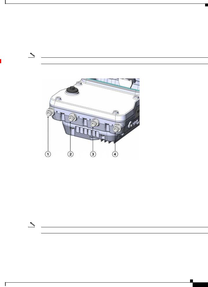
Figure 1-8 1/2-NPT I/O Ports
1 |
AC or DC input |
3 |
PoE port |
|
|
|
|
2 |
PoE port |
4 |
Fiber port |
|
|
|
|
Loctite 565 Thread Sealant needs to be applied to the threads prior to the installation, as shown in the following figure. Customer should supply certified 1/2” NPT conduit, gland, or adapter for each port used for appropriate installation. (For example, Sealcon provides glands and adapters that are certified. See https://www.sealconex.com/?ex=9wkuir-fln65y-13897wy-drrs7y.)
Cisco Catalyst IW6300 Heavy Duty Series Access Point Hardware Installation Guide
1-10
Chapter 1 Overview
Hardware Features
REVIEW DRAFT —CISCO CONFIDENTIAL
Optional Hardware
Depending on the order configuration, the following optional access point hardware may be part of the shipment:
•Cisco Aironet Antennas
•Pole mount kits (IOT-ACCPMK)
•Band installation tool for pole mount kit (AIR-BAND-INS-TL=)
•Power injector (AIR-PWRINJ-60RGDx=)
•1000BASE-LX single-mode rugged SFP (GLC-LX-SM-RGD=)
•1000BASE-SX multi-mode rugged SFP (GLC-SX-MM-RGD=)
•100BaseBX10-U rugged SFP (GLC-FE-100BX-URGD=)
•100BASE-FX rugged SFP (GLC-FE-100FX-RGD=)
•100BASE-LX10 rugged SFP (GLC-FE-100LX-RGD=)
•1000BASE-T rugged SFP (GLC-T-RGD=)
Cisco Catalyst IW6300 Heavy Duty Series Access Point Hardware Installation Guide
1-11

Chapter 1 Overview
Hardware Features
REVIEW DRAFT—CISCO CONFIDENTIAL
Cisco Catalyst IW6300 Heavy Duty Series Access Point Hardware Installation Guide
1-12

REVIEW DRAFT —CISCO CONFIDENTIAL
C H A P T E R 2
Before You Begin
This chapter describes what steps you need to take before beginning the installation of your Access Point and contains the following sections:
•Unpacking the Access Point, page 2-1
•Tools and Hardware, page 2-2
•Warnings, page 2-3
•Safety Information, page 2-3
•Avoiding Damage to Radios in a Testing Environment, page 2-5
•Installation Guidelines, page 2-7
Unpacking the Access Point
When you are unpacking the access point, do not remove the foam blocks attached to the antenna connectors. The foam protects the antenna connectors during installation.
To unpack the access point, follow these steps:
Step 1 Open the shipping container and carefully remove the contents.
Step 2 Return all packing materials to the shipping container, and save it.
Step 3 Ensure that all items listed in “Package Contents” section on page 2-1 are included in the shipment. If any item is damaged or missing, notify your sales representative.
Package Contents
The typical access point package contains the following items:
•Access point
–IW-6300H-AC-X-K9 (AC power model)
–IW-6300H-DC-X–K9 (DC power model)
–IW-6300H-DCW-X-K9 (DC wide range power model)
•Mount kit (IOT-ACCPMK)
Cisco Catalyst IW6300 Heavy Duty Series Access Point Hardware Installation Guide
2-1

Chapter 2 Before You Begin
Tools and Hardware
REVIEW DRAFT—CISCO CONFIDENTIAL
•Ground lug and screws with lock washers
•Weatherization tape and anti-seize compound
Tools and Hardware
The tools and hardware used to install the access point are described in:
•Optional Tools and Hardware, page 2-2
•Optional Tools and Hardware That You Supply, page 2-2
•Pole Installation Hardware and Tools, page 2-3
Optional Tools and Hardware
The optional tools and hardware that can be obtained from Cisco are:
•Optional power injector (AIR-PWRINJ-60GRDx=)
•Antennas, 2.4/5-GHz
•Optional banding strap tool (BAND IT) (AIR-BAND-INST-TL=)
Optional Tools and Hardware That You Supply
Tools and materials that are user-supplied are:
•1/2” or 13-mm socket wrench, used to open the Access Cover and to attach the mounting bracket
•#2 Phillips or Flat screw driver to clamp wire terminal and ground terminal
•3/8” Allen wrench with 13-18" long wrench handle to remove 1/2” NPT port plugs
•Loctite 565 Thread Sealant for 1/2” NPT Ports
•6-AWG copper ground wire
•Ethernet RJ-45 connector and installation tool
•Optional ground rod, as required by local regulations
•Optional ladder, power lift, rope, or other tools as required
•ESD-preventive cord and wrist strap.
•Wire-stripping tools for stripping 14and 18-gauge wires
•Crimping tool
If installed in a hazardous location, please note the additional items (see Product Document of Compliance for further details)
•ATEX certified Armored cable for routing in conduit
•Customer supplied ATEX certified 1/2” NPT conduit (rigid or flex), or ATEX certified cable gland or barrier gland for each connection
•ATEX-certified AC or DC power cable, based on the AP model ordered
Cisco Catalyst IW6300 Heavy Duty Series Access Point Hardware Installation Guide
2-2
Loading...