


 Loading...
Cisco Firepower 1010 Hardware Installation Guide
First Published: 2019-07-24
Last Modified: 2019-09-01
Americas Headquarters
Cisco Systems, Inc. 170 West Tasman Drive
San Jose, CA 95134-1706 USA http://www.cisco.com Tel: 408 526-4000
800 553-NETS (6387) Fax: 408 527-0883
THE SPECIFICATIONS AND INFORMATION REGARDING THE PRODUCTS IN THIS MANUAL ARE SUBJECT TO CHANGE WITHOUT NOTICE. ALL STATEMENTS, INFORMATION, AND RECOMMENDATIONS IN THIS MANUAL ARE BELIEVED TO BE ACCURATE BUT ARE PRESENTED WITHOUT WARRANTY OF ANY KIND, EXPRESS OR IMPLIED. USERS MUST TAKE FULL RESPONSIBILITY FOR THEIR APPLICATION OF ANY PRODUCTS.
THE SOFTWARE LICENSE AND LIMITED WARRANTY FOR THE ACCOMPANYING PRODUCT ARE SET FORTH IN THE INFORMATION PACKET THAT SHIPPED WITH THE PRODUCT AND ARE INCORPORATED HEREIN BY THIS REFERENCE. IF YOU ARE UNABLE TO LOCATE THE SOFTWARE LICENSE OR LIMITED WARRANTY, CONTACT YOUR CISCO REPRESENTATIVE FOR A COPY.
The Cisco implementation of TCP header compression is an adaptation of a program developed by the University of California, Berkeley (UCB) as part of UCB's public domain version of the UNIX operating system. All rights reserved. Copyright © 1981, Regents of the University of California.
NOTWITHSTANDING ANY OTHER WARRANTY HEREIN, ALL DOCUMENT FILES AND SOFTWARE OF THESE SUPPLIERS ARE PROVIDED “AS IS" WITH ALL FAULTS. CISCO AND THE ABOVE-NAMED SUPPLIERS DISCLAIM ALL WARRANTIES, EXPRESSED OR IMPLIED, INCLUDING, WITHOUT LIMITATION, THOSE OF MERCHANTABILITY, FITNESS FOR A PARTICULAR PURPOSE AND NONINFRINGEMENT OR ARISING FROM A COURSE OF DEALING, USAGE, OR TRADE PRACTICE.
IN NO EVENT SHALL CISCO OR ITS SUPPLIERS BE LIABLE FOR ANY INDIRECT, SPECIAL, CONSEQUENTIAL, OR INCIDENTAL DAMAGES, INCLUDING, WITHOUT LIMITATION, LOST PROFITS OR LOSS OR DAMAGE TO DATA ARISING OUT OF THE USE OR INABILITY TO USE THIS MANUAL, EVEN IF CISCO OR ITS SUPPLIERS HAVE BEEN ADVISED OF THE POSSIBILITY OF SUCH DAMAGES.
Any Internet Protocol (IP) addresses and phone numbers used in this document are not intended to be actual addresses and phone numbers. Any examples, command display output, network topology diagrams, and other figures included in the document are shown for illustrative purposes only. Any use of actual IP addresses or phone numbers in illustrative content is unintentional and coincidental.
All printed copies and duplicate soft copies of this document are considered uncontrolled. See the current online version for the latest version.
Cisco has more than 200 offices worldwide. Addresses and phone numbers are listed on the Cisco website at www.cisco.com/go/offices.
CiscoandtheCiscologoaretrademarksorregisteredtrademarksofCiscoand/oritsaffiliatesintheU.S. andothercountries. ToviewalistofCiscotrademarks,gotothisURL: www.cisco.com go trademarks. Third-party trademarks mentioned are the property of their respective owners. The use of the word partner does not imply a partnership relationship between Cisco and any other company. (1721R)
© 2019 Cisco Systems, Inc. All rights reserved.

C H A P T E R 1
C H A P T E R 2
C H A P T E R 3
C O N T E N T S
Overview 1 |
|
|
|
|
|
|
|
Features |
1 |
|
|
|
|
|
|
Package Contents |
4 |
|
|
|
|
||
Serial Number Location |
5 |
|
|
||||
Front Panel |
6 |
|
|
|
|
|
|
Rear Panel |
6 |
|
|
|
|
|
|
Status LEDs |
7 |
|
|
|
|
|
|
Hardware Specifications |
9 |
|
|
||||
Product ID Numbers |
10 |
|
|
|
|||
Power Cord Specifications |
10 |
|
|||||
Installation Preparation |
|
17 |
|
|
|
||
Installation Warnings |
17 |
|
|
|
|||
Position the Chassis |
20 |
|
|
|
|||
Safety Recommendations |
|
20 |
|
||||
Maintain Safety with Electricity |
21 |
||||||
Prevent ESD Damage |
21 |
|
|
|
|||
Site Environment |
22 |
|
|
|
|||
Site Considerations |
|
22 |
|
|
|
||
Power Supply Considerations |
22 |
||||||
Rack Configuration Considerations 23 |
|||||||
Mount the Chassis |
25 |
|
|
|
|
|
|
Unpack and Inspect the Chassis |
25 |
||||||
Desktop-Mount the Chassis |
26 |
||||||
Wall-Mount the Chassis |
26 |
|
|||||
Cisco Firepower 1010 Hardware Installation Guide
iii

Contents
C H A P T E R 4
iv
Rack-Mount the Chassis |
29 |
Connect to the Console Port |
33 |
Connect to the Console Port with Microsoft Windows 33
Connect to the Console Port with Mac OS X 35
Connect to the Console Port with Linux 35
Cisco Firepower 1010 Hardware Installation Guide

C H A P T E R 1
Overview
•Features, on page 1
•Package Contents, on page 4
•Serial Number Location, on page 5
•Front Panel, on page 6
•Rear Panel, on page 6
•Status LEDs, on page 7
•Hardware Specifications, on page 9
•Product ID Numbers, on page 10
•Power Cord Specifications, on page 10
Features
The Cisco Firepower 1010 security appliance is an NGFW desktop product in the Cisco Firepower family of devices with PoE+ and L2 switch support.
Note The PoE+ and L2 switch features are supported in a future software release.
The Firepower 1010 supports Cisco Firepower software version 6.4 and later. See the Cisco Firepower CompatibilityGuide,whichprovidesCiscoFirepowersoftwareandhardwarecompatibility,includingoperating system and hosting environment requirements, for each supported Firepower version.
See Product ID Numbers, on page 10 for a list of the product IDs (PIDs) associated with the Firepower 1010.
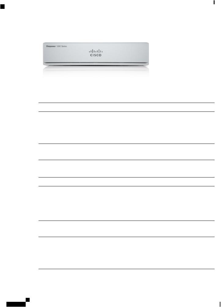
The following figure shows the Cisco Firepower 1010.
Cisco Firepower 1010 Hardware Installation Guide
1
Overview
Features
Figure 1: Firepower 1010
The following table lists the features for the Firepower 1010.
Table 1: Firepower 1010 Features
Feature |
Description |
|
Form factor |
1 RU |
|
Mounting |
Desktop mount |
|
|
Wall mount (Cisco part number 69-100647-01) |
|
|
Rack mount (Cisco part number 69-100648-01) |
|
Airflow |
Side-to-side |
|
|
No fan |
|
Processor |
One 4-core Intel CPU |
|
Memory |
8-GB DDR4 DRAM |
|
Boot partition |
8 GB (internal) |
|
L2 switch |
Marvell SOHO 88E6390 |
|
|
Note |
Supported in a future software release |
Management |
One Gigabit Ethernet RJ-45 10/100/1000 BaseT |
|
port |
Restricted to network management access; connect with an RJ-45 cable |
|
|
||
Console port |
One RJ-45 |
|
|
Use to access management through an external system |
|
USB Mini B |
One USB Mini B |
|
port |
Use to access management through an external system |
|
|
||
USB port |
One USB 3.0 Type A |
|
|
Use to attach an external device such as storage |
|
Cisco Firepower 1010 Hardware Installation Guide
2

Overview
Features
Network ports Eight Gigabit Ethernet RJ-45 10/100/1000 BaseT
Each RJ-45 (8P8C) copper port supports auto MDI/X as well as auto-negotiation for interface speed, duplex, and other negotiated parameters, and are MDI/MDIX-compliant.
The ports are numbered (from top to bottom, left to right) 1, 2, 3, 4, 5, 6, 7, 8. Each port includes a pair of LEDs, one each for connection status and link status. The ports are named and numbered Gigabit Ethernet 1/1 through Gigabit Ethernet 1/8.
Note Youcanuseports7and8asPoE+ports. PoE+issupportedinafuturesoftware
release.
PoE+ controller |
Yes |
|
card |
Note |
Ports 7 and 8 are PoE+ ports. Supported in a future software release. |
|
||
Lock slot |
Yes |
|
|
Accepts a standard Kensington T-bar locking mechanism for securing the chassis |
|
Reset button |
Yes |
|
|
A small recessed button that if pressed for longer than three seconds resets the chassis to |
|
|
its default state following the next reboot. Configuration variables are reset to factory |
|
|
default, but the flash is not erased and no files are removed. |
|
Power switch |
No |
|
|
To shut down the Firepower 1010, remove the AC power supply. |
|
|
Note |
To shut down the Firepower 1010 gracefully, see the "Power Off the Device" |
|
|
topic for FDM and FMC in the Cisco Firepower 1010 Getting Started Guide. |
Power cord |
Yes |
|
socket |
The chassis is powered on when you plug in the AC power supply. |
|
|
||
AC power |
One external AC power supply |
|
supply |
The power supply has a total of 115 W of power. There is 55 W of +12-V system power |
|
|
||
|
and 60 W of -53.5-V PoE power. |
|
|
Note |
PoE+ is supported in a future software release. |
|
Note |
Use the power supply (part number 341-100765-01) that shipped with the |
|
|
chassis. It supports PoE+. |
Storage |
One 200-GB M.2 SATA SSD drive |
|
|
The drive is used by the software; there is no user access to the drive. |
|
|
The drive is not field-replaceable; you must return the chassis to Cisco for drive |
|
|
replacement. |
|
Rubber feet |
Four rubber feet on the bottom of the chassis |
|
|
Note |
The rubber feet are needed for proper cooling. Do not remove them. |
Cisco Firepower 1010 Hardware Installation Guide
3

Overview
Package Contents
Console Ports
The Firepower 1010 has two external console ports, a standard RJ-45 port and a USB Mini B serial port. Only one console port can be active at a time. When a cable is plugged into the USB console port, the RJ-45 port becomes inactive. Conversely, when the USB cable is removed from the USB port, the RJ-45 port becomes active. The console ports do not have any hardware flow control. You can use the CLI to configure the chassis through either serial console port by using a terminal server or a terminal emulation program on a computer.
•RJ-45 (8P8C) port—Supports RS-232 signaling to an internal UART controller. The RJ-45 console port does not support a remote dial-in modem. You can use a standard management cable (Cisco part number 72-3383-01) to convert the RJ45-to-DB9 connection if necessary.
•USBMiniBport—LetsyouconnecttoaUSBportonanexternalcomputer. ForLinuxandMacintosh systems, no special driver is required. For Windows systems, you must download and install a USB driver (available on software.cisco.com). You can plug and unplug the USB cable from the console port without affecting Windows HyperTerminal operations. We recommend shielded USB cables with properly terminated shields. Baud rates for the USB console port are 1200, 2400, 4800, 9600, 19200, 38400, 57600, and 115200 bps.
Note For Windows operating systems, you must install a Cisco Windows USB Console Driver on any PC connected to the console port before using the USB console port. See Connect to the Console Port with Microsoft Windows for information on installing the driver.
External Flash Storage
The chassis contains a standard USB Type A port that you can use to attach an external device. The USB port can provide output power of 5 V and up to a maximum of 1A (5 USB power units).
•External USB drive (optional)—You can use the external USB Type A port to attach a data-storage device. The external USB drive identifier is disk1. When the chassis is powered on, a connected USB drive is mounted as disk1 and is available for you to use. Additionally, the file-system commands that are available to disk0 are also available to disk1, including copy, format, delete, mkdir, pwd, cd, and so on.
•FAT-32 File System—The Firepower 1010 only supports FAT-32-formatted file systems for the external USB drive. If you insert an external USB drive that is not in FAT-32 format, the system mounting process fails, and you receive an error message. You can enter the command format disk1: toformatthepartitiontoFAT-32andmountthepartitiontodisk1again;however,datamight be lost.
Package Contents
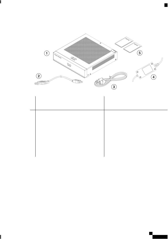
The following figure shows the package contents for the Firepower 1010. Note that the contents are subject to change and your exact contents might contain additional or fewer items.
Cisco Firepower 1010 Hardware Installation Guide
4
Overview
Serial Number Location
Figure 2: Firepower 1010 Package Contents
1 |
Chassis |
2 |
USB console cable (Type A to Type B) |
3 |
Power cord |
4 |
Power supply |
5Useful Links Cisco Firepower 1010
ThestepsintheUsefulLinksdocumentsendyou to the documentation you need to install, set up, and configure your 1010.
Start Here Cisco Firepower 1010 for Firepower Threat Defense
This document tells how to cable and set up the FTDusingFirepowerDeviceManager(FDM)(a simplified,singledevicemanagerincludedonthe device).
Serial Number Location
You can view the serial number and additional model information on the compliance label located on the bottom of the chassis. The following figure shows a sample compliance label.
Cisco Firepower 1010 Hardware Installation Guide
5

Overview
Front Panel
Figure 3: Compliance Label on the Firepower Chassis
Front Panel
The following figure shows the front panel of the Firepower 1010. Note that there are no connectors or LEDs on the front panel.
Figure 4: Firepower 1010 Front Panel
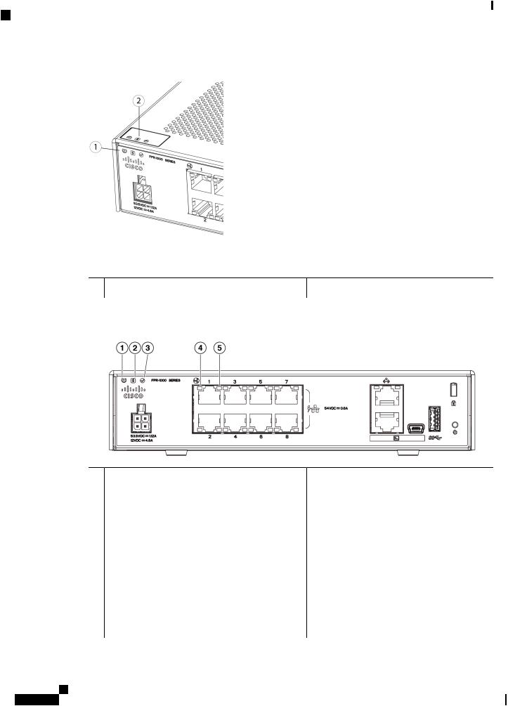
Rear Panel
ThefollowingfigureshowstherearpaneloftheFirepower1010. See StatusLEDs,onpage7 foradescription
of the LEDs.
Cisco Firepower 1010 Hardware Installation Guide
6
Overview
Status LEDs
Figure 5: Firepower 1010 Rear Panel
1 |
Status LEDs |
2 |
Management port |
3 |
Lock slot |
4 |
Power cord socket |
5 |
Network data ports |
6 |
Console port |
7 |
USB Mini B port |
8 |
USB Type A port |
9 |
Reset button |
10 |
Rubber feet |
Status LEDs
Facing the rear of the chassis, the LEDs are located on the top left edge (facing the front of the chassis, they are in the back right corner of the top). The network port LEDs are at the top sides of each network port.
The following figure shows the status LEDs on the rear panel and on the cover of the chassis.
Cisco Firepower 1010 Hardware Installation Guide
7
Overview
Status LEDs
Figure 6: Firepower 1010 Status LEDs
1Power,Status,andActiveLEDsonrearofchassis 2 Power,Status,andActiveLEDsontopofchassis
The following figure shows all of the LEDs on the rear panel and describes their states.
Figure 7: Firepower 1010 Rear Panel LEDs
1 Power |
2 Status |
Power supply status: |
System operating status: |
• Off —Power supply off. |
• Green—Normal system function. |
• Green—Power supply on. |
• Amber—Critical alarm indicating one or |
|
more of the following: |
|
• Majorfailureofahardwareorsoftware |
|
component. |
|
• Over-temperature condition. |
|
• Power voltage outside the tolerance |
|
range. |
Cisco Firepower 1010 Hardware Installation Guide
8
Loading...