


Linksys PAP2 and RT31P2
PHONE ADAPTER Administration Guide
August 2004
© 2004 Linksys Proprietary (See Copyright Notice on Page 2) |
1 |

Disclaimer – Please Read:
This document contains implementation examples and techniques using Linksys and, in some instances, other company’s technology and products and is a recommendation only and does not constitute any legal arrangement between Linksys and the reader, either written or implied. The conclusions reached and recommendations and statements made are based on generic network, service and application requirements and should be regarded as a guide to assist you in forming your own opinions and decision regarding your particular situation. As well, Linksys Technology reserves the right to change the features and functionalities for products described in this document at any time. These changes may involve changes to the described solutions over time.
Use of Proprietary Information and Copyright Notice:
Major portions of this document are the sole property of Sipura Technology,
Inc. and are provided to its licensee, Linksys LLC., and protected by United
States and international copyright laws. (c)2003-2004 Sipura technology,
Inc. - All rights reserved.
© 2004 Linksys Proprietary (See Copyright Notice on Page 2) |
2 |
Table of Contents
1. |
Introduction |
.................................................................................................................................... |
6 |
|
|
1.1. |
The Session Initiation Protocol ............................................................................................. |
6 |
|
|
1.1.1. Components of a SIP Network ....................................................................................................... |
8 |
||
|
1.1.2. |
Provisioning Overview.................................................................................................................... |
9 |
|
|
1.1.3. |
Security .........................................................................................................................Overview |
10 |
|
|
1.1.3.1. ...................................................................................................................... |
Proxy Servers |
11 |
|
|
1.1.4. |
SIP ..................................................................................................................................Services |
11 |
|
|
1.1.4.1. ..................................................................................................................... |
Basic Services |
12 |
|
|
1.1.4.2. .............................................................................................................. |
Enhanced Services |
12 |
|
|
1.1.4.3. ............................................................................................................... |
PSTN Interworking |
14 |
|
|
1.2. |
Network ...................................................................Address Translation (NAT) Traversal |
15 |
|
|
1.2.1. What .......................................................is a NAT or NAPT (Network Address Port Translator)? |
15 |
||
|
1.2.2. |
VoIP ..................................................................................................................-NAT Interworking |
16 |
|
|
1.3. |
Voice Quality .......................................................................................................Overview |
16 |
|
2. |
Hardware Overview..................................................................................................................... |
17 |
||
|
2.1. |
Phone .................................................................................................Adapter LED Status |
19 |
|
|
2.2. |
Broadband ..........................................................................Router (RT31P2) LED Status |
19 |
|
3. |
Software Configuration ...........................................................................................Mechanisms |
20 |
||
|
3.1. |
Configuration .............................................................................................Profile Formats |
21 |
|
|
3.1.1. Using ......................................................................................the Supplemental Profile Compiler |
23 |
||
|
3.1.2. Encrypting ...................................................................and Compressing XML configuration files |
24 |
||
|
3.2. |
Secure .................................................................................................Initial Configuration |
25 |
|
|
3.3. |
Web Interface ..................................................................................................................... |
26 |
|
|
3.3.1. |
Web ...........................................................................................................Interface Conventions |
26 |
|
|
3.3.2. |
Administration ...............................................................................................................Privileges |
27 |
|
|
3.3.3. Basic ...........................................................................................................and Advanced Views |
27 |
||
|
3.4. |
Functional ...........................................................................................Configuration URLs |
27 |
|
|
3.4.1. |
Upgrade ................................................................................................................................URL |
27 |
|
|
3.4.2. |
Resync ..................................................................................................................................URL |
28 |
|
|
3.4.3. |
Reboot ..................................................................................................................................URL |
28 |
|
|
3.5. |
Configuration ...............................................................................via the IVR (PAP2 only) |
29 |
|
4. |
Configuration ...........................................................................................................Parameters |
32 |
||
|
4.1. |
Data Types.......................................................................................................................... |
32 |
|
|
4.1.1. |
Conventions .................................................................................................................................. |
35 |
|
|
4.2. |
Provisioning .......................................................................................Related Parameters |
35 |
|
|
4.2.1. |
Firmware .........................................................................................................................Upgrade |
43 |
|
|
4.2.2. |
Provisioning ..................................................................................................Server Redundancy |
46 |
|
|
4.2.3. Configuring ............................................................................................the Web Server and IVR |
46 |
||
|
System Configuration .................................................................................................................................. |
46 |
||
|
4.3. |
Basic Networking .........................................................................................Configuration |
47 |
|
|
Network Configuration ................................................................................................................................. |
47 |
||
|
4.4. |
Basic Account ...............................................................................................Configuration |
48 |
|
|
4.5. |
Configuration .........................................................................................for NAT Traversal |
49 |
|
|
4.6. |
Media ..........................................and SDP (Session Description Protocol) Configuration |
51 |
|
|
4.6.1. |
DTMF ....................................................................................................................and Hookflash |
51 |
|
|
4.6.2. Codec .............................................................................................................and Audio Settings |
52 |
||
|
4.6.3. Dynamic .........................................................................Payload Types and SDP Codec Names |
53 |
||
|
4.6.4. |
Secure ......................................................................................................Media Implementation: |
54 |
|
|
4.6.5. Outbound ........................................................................................Call Codec Selection Codes: |
56 |
||
|
4.7. |
Supplementary .....................................................................................................Services |
57 |
|
|
4.7.1. Supplementary .................................................................................Services activated internally |
58 |
||
|
4.7.2. Call ........................................................................................Forwarding Implemented internally |
60 |
||
|
4.7.3. Supplementary .........................................Services implemented in the service provider network |
60 |
||
|
4.8. |
Dial Plan .......................................................................................................Configuration |
61 |
|
|
4.8.1. |
Speed ..................................................................................................................Dialing Settings |
66 |
|
|
|
|||
© 2004 Linksys Proprietary (See Copyright Notice on Page 2) |
3 |
|||
|
4.9. |
Progress Tone and Ring Configuration .............................................................................. |
67 |
|
|
4.9.1. Distinctive Ring and Other Ring Settings ...................................................................................... |
67 |
||
|
4.9.2. |
Progress Tones............................................................................................................................. |
69 |
|
|
4.10. |
Less Frequently Used Paramters ....................................................................................... |
70 |
|
|
4.10.1. |
Advanced Protocol Parameters ................................................................................................ |
70 |
|
|
4.10.2. |
Additional User Account Information ........................................................................................ |
73 |
|
|
4.10.3. |
Per-Line Polarity Settings ......................................................................................................... |
75 |
|
|
4.10.4. |
Additional Timer Values (sec)................................................................................................... |
75 |
|
|
4.10.5. |
Miscellaneous Parameters ....................................................................................................... |
76 |
|
5. |
Expected Feature Behavior......................................................................................................... |
79 |
||
|
5.1. |
Originating a Phone Call..................................................................................................... |
79 |
|
|
5.2. |
Receiving a Phone Call ...................................................................................................... |
79 |
|
|
5.3. |
Caller ID.............................................................................................................................. |
80 |
|
|
5.4. |
Calling Line Identification Presentation (CLIP)................................................................... |
80 |
|
|
5.5. |
Calling Line Identification Restriction (CLIR) – Caller ID Blocking ..................................... |
81 |
|
|
5.6. |
Call Waiting......................................................................................................................... |
81 |
|
|
5.7. |
Disable or Cancel Call Waiting ........................................................................................... |
82 |
|
|
5.8. |
Call-Waiting with Caller ID .................................................................................................. |
83 |
|
|
5.9. |
Voice Mail ........................................................................................................................... |
83 |
|
|
5.10. |
Attendant Call Transfer....................................................................................................... |
84 |
|
|
5.11. |
Unattended or “Blind” Call Transfer.................................................................................... |
85 |
|
|
5.12. |
Call Hold ............................................................................................................................. |
85 |
|
|
5.13. |
Three-Way Calling .............................................................................................................. |
86 |
|
|
5.14. |
Three-Way Ad-Hoc Conference Calling ............................................................................. |
86 |
|
|
5.15. |
Call Return.......................................................................................................................... |
87 |
|
|
5.16. |
Automatic Call Back............................................................................................................ |
87 |
|
|
5.17. |
Call FWD – Unconditional................................................................................................... |
88 |
|
|
5.18. |
Call FWD – Busy ................................................................................................................ |
89 |
|
|
5.19. |
Call FWD - No Answer........................................................................................................ |
89 |
|
|
5.20. |
Anonymous Call Blocking ................................................................................................... |
90 |
|
|
5.21. |
Distinctive / Priority Ringing and Call Waiting Tone ........................................................... |
90 |
|
|
5.22. |
Speed Calling – Up to Eight (8) Numbers or IP Addresses................................................ |
91 |
|
6. |
Troubleshooting........................................................................................................................... |
92 |
||
|
6.1. |
Call Statistics Reporting...................................................................................................... |
92 |
|
|
6.2. |
Enabling Logging and Debugging ...................................................................................... |
93 |
|
|
6.3. |
Error and Log Reporting ..................................................................................................... |
93 |
|
|
6.4. |
Internal Error Codes ........................................................................................................... |
93 |
|
|
6.5. |
Provisioning and Upgrade result codes.............................................................................. |
94 |
|
|
6.6. |
Table of SIP Response Codes (Error Codes) .................................................................... |
94 |
|
7. Summary of Implemented Features and Specifications.............................................................. |
95 |
|||
|
7.1. |
Data Networking Features .................................................................................................. |
95 |
|
|
7.1.1. MAC Address (IEEE 802.3)........................................................................................................... |
95 |
||
|
7.1.2. IPv4 – Internet Protocol Version 4 (RFC 791) upgradeable to v6 (RFC 1883).............................. |
96 |
||
|
7.1.3. ARP – Address Resolution Protocol.............................................................................................. |
96 |
||
|
7.1.4. DNS – A Record (RFC 1706), SRV Record (RFC 2782)............................................................... |
96 |
||
|
7.1.5. DiffServ (RFC 2475) and ToS – Type of Service (RFC 791/1349) ................................................ |
96 |
||
|
7.1.6. DHCP Client – Dynamic Host Configuration Protocol (RFC 2131)................................................ |
96 |
||
|
7.1.7. ICMP – Internet Control Message Protocol (RFC792) .................................................................. |
96 |
||
|
7.1.8. TCP – Transmission Control Protocol (RFC793)........................................................................... |
96 |
||
|
7.1.9. UDP – User Datagram Protocol (RFC768).................................................................................... |
96 |
||
|
7.1.10. |
RTP – Real Time Protocol (RFC 1889) (RFC 1890)................................................................. |
96 |
|
|
7.1.11. |
RTCP – Real Time Control Protocol (RFC 1889) ..................................................................... |
96 |
|
|
7.2. |
Voice Features.................................................................................................................... |
96 |
|
|
7.2.1. |
SIPv2 – Session Initiation Protocol Version 2 (RFC 3261-3265).................................................. |
96 |
|
|
7.2.1.1. |
SIP Proxy Redundancy – Static or Dynamic via DNS SRV ................................................. |
96 |
|
|
7.2.1.2. |
Re-registration with Primary SIP Proxy Server .................................................................... |
96 |
|
|
|
|||
© 2004 Linksys Proprietary (See Copyright Notice on Page 2) |
4 |
|||

|
|
7.2.1.3. |
SIP Support in Network Address Translation Networks – NAT ............................................ |
96 |
|
|
7.2.2. |
Codec Name Assignment.............................................................................................................. |
96 |
||
|
7.2.3. |
Secure Calls.................................................................................................................................. |
97 |
||
|
7.2.4. |
Voice Algorithms: .......................................................................................................................... |
97 |
||
|
|
7.2.4.1. |
G.711 (A - law and mµ - law) ................................................................................................... |
97 |
|
|
|
7.2.4.2. |
G.726 ................................................................................................................................... |
97 |
|
|
|
7.2.4.3. |
G.729A ................................................................................................................................ |
97 |
|
|
|
7.2.4.4. |
G.723.1 ................................................................................................................................ |
97 |
|
|
7.2.5. |
Codec Selection ............................................................................................................................ |
97 |
||
|
7.2.6. |
Dynamic Payload .......................................................................................................................... |
97 |
||
|
7.2.7. Adjustable Audio Frames Per Packet............................................................................................ |
97 |
|||
|
7.2.8. Fax Tone Detection Pass-Through................................................................................................ |
97 |
|||
|
7.2.9. DTMF: In-band & Out-of-Band (RFC 2833) (SIP INFO *).............................................................. |
97 |
|||
|
7.2.10. |
|
Call Progress Tone Generation ................................................................................................ |
98 |
|
|
7.2.11. |
|
Call Progress Tone Pass Through ............................................................................................ |
98 |
|
|
7.2.12. |
|
Jitter Buffer – Dynamic (Adaptive) ............................................................................................ |
98 |
|
|
7.2.13. |
|
Full Duplex Audio ..................................................................................................................... |
98 |
|
|
7.2.14. |
|
Echo Cancellation – Up to 8 ms Echo Tail ............................................................................... |
98 |
|
|
7.2.15. |
|
Voice Activity Detection with Silence Suppression & Comfort Noise Generation ..................... |
98 |
|
|
7.2.16. |
|
Attenuation / Gain Adjustment .................................................................................................. |
98 |
|
|
7.2.17. |
|
Signaling Hook Flash Event ..................................................................................................... |
98 |
|
|
7.2.18. |
|
Configurable Flash / Switch Hook Timer .................................................................................. |
99 |
|
|
7.2.19. |
|
Configurable Dial Plan with Interdigit Timers ............................................................................ |
99 |
|
|
7.2.20. |
|
Message Waiting Indicator Tones – MWI ................................................................................. |
99 |
|
|
7.2.21. |
|
Polarity Control ......................................................................................................................... |
99 |
|
|
7.2.22. |
|
Calling Party Control – CPC ..................................................................................................... |
99 |
|
|
7.2.23. |
|
International Caller ID Delivery ................................................................................................. |
99 |
|
|
7.2.24. |
|
Streaming Audio Server – SAS .............................................................................................. |
100 |
|
|
7.2.25. |
|
Music On Hold – MOH ............................................................................................................ |
100 |
|
7.3. |
Security Features.............................................................................................................. |
102 |
|||
|
7.3.1. Multiple Administration Layers (Levels and Permissions) ........................................................... |
102 |
|||
|
7.3.2. HTTP Digest – Encrypted Authentication via MD5 (RFC 1321) .................................................. |
102 |
|||
|
7.3.3. HTTPS with Client Certificate...................................................................................................... |
102 |
|||
7.4. |
Administration and Maintenance Features ....................................................................... |
102 |
|||
|
7.4.1. Web Browser Administration and Configuration via Integral Web Server.................................... |
102 |
|||
|
7.4.2. Telephone Key Pad Configuration with Interactive Voice Prompts.............................................. |
102 |
|||
|
7.4.3. Automated Provisioning & Upgrade via TFTP, HTTP and HTTPS.............................................. |
102 |
|||
|
7.4.4. Periodic Notification of Upgrade Availability via NOTIFY or HTTP.............................................. |
102 |
|||
|
7.4.5. |
Non-Intrusive, In-Service Upgrades ............................................................................................ |
102 |
||
|
7.4.6. Report Generation and Event Logging ........................................................................................ |
102 |
|||
|
7.4.7. Syslog and Debug Server Records ............................................................................................. |
102 |
|||
8. |
List of all configuration parameters ........................................................................................... |
102 |
|||
9. |
Acronyms |
................................................................................................................................... |
113 |
||
10. |
|
Glossary ................................................................................................................................ |
115 |
||
© 2004 Linksys Proprietary (See Copyright Notice on Page 2) |
5 |

1. Introduction
This guide describes basic administration and use of the Linksys Technology PHONE ADAPTER phone adapter – an intelligent low-density Voice over IP (VoIP) gateway. The PHONE ADAPTER enables carrier class residential and business IP Telephony services delivered over broadband or high-speed Internet connections. By intelligent, we mean the PHONE ADAPTER maintains the states of all the calls it terminates. It is capable of making proper decisions in reaction to user input events (such as on/off hook or hook flash) with little or no involvement by a ‘middle-man’ server or media gateway controller.
Examples of proper reactions are: playing dial tone, collecting DTMF digits, comparing them against a dial plan and terminating a call. With intelligent endpoints at the edges of a network, performing the bulk of the call processing duties, the deployment of a large network with thousands of subscribers can scale quickly without the introduction of complicated, expensive servers. As described later in this section, the Session Initiation Protocol (SIP) is a good choice of call signaling protocol for the implementation of such a device in this type of network.
The phenomenal growth of broadband Internet access (DSL, Cable, FTTH, etc.), has brought the realization of reliable packet switched IP Telephony Services with circuit switched toll-quality and subscriber feature transparency with that of the PSTN’s CLASS feature-set. In addition to basic offerings comparable to traditional PSTN services, many service providers have integrated their IP Telephony offering with a large number of web-based productivity applications like unified messaging and call management features such as, remote call forward configuration via the web. Such advances over traditional phone services, with equal or better voice quality and lower per-minute prices, have made IP Telephony service a viable business. In fact, IP Telephony service providers in the US and abroad have seen their subscriber base growing at a rapid pace.
The technical challenges in deploying and operating a residential IP Telephony service, however, are not small. One of the main challenges is to make the service transparent to subscribers: The subscribers shall expect to use their existing phones to make or receive calls in the same way as with the existing PSTN service. To enable this level of transparency, the IP Telephony solution has to be tightly integrated. A key element in this end-to-end IP Telephony solution is the provision of an endpoint device that sits at a subscriber’s premises that serves as an IP Telephony gateway or telephone adapter. This phone adapter offers one or more standard telephone RJ-11 phone ports – identical to the phone wall jacks at home – where the subscriber can plug in their existing telephone equipment to access phone services. The IP Telephony gateway may connect to the IP network, like the Internet, through an uplink Ethernet connection.
Important!! Please note: The information contained herein is not a warranty from Linksys Customers planning to use the PHONE ADAPTER in a VoIP service deployment are warned to test all functionality they plan to support in conjunction with the PHONE ADAPTER before putting the PHONE ADAPTER in service. Some information in Section 1 of this guide is written for educational purposes and describes functionality not yet implemented in the PHONE ADAPTER.
1.1.The Session Initiation Protocol
There are many excellent articles and books that discuss the advantages of SIP.i Here are some of the more popular details:
•SIP message constructs are very similar to those of HTTP which is well-known to be IP Network (Internet) friendly.
•SIP is transport agnostic – meaning it can be used over TCP/IP or UDP/IP, with or without security.
•SIP has a better chance of traversing NATs than other control protocols.
© 2004 Linksys Proprietary (See Copyright Notice on Page 2) |
6 |

•SIP enables the implementation of intelligent endpoints to support scalable advanced services.
In a nutshell, SIP is a distributed signaling protocol (as opposed to a centralized protocol such as SS7, MGCP or MEGACO/H.248). With a distributive protocol, the intelligence does not necessarily reside on a central server, but can be built into the individual endpoints. By moving the intelligence to reside within the endpoints at the edge of the network, the processing load of the network application and associated call servers are significantly reduced, thus making the network a very scalable solution.
© 2004 Linksys Proprietary (See Copyright Notice on Page 2) |
7 |

1.1.1.Components of a SIP Network
Service
Provider
Domain
Subscriber
Database
Provisioning |
|
SIP |
|
Billing |
|
Application |
|
Application |
Server |
|
Proxy Server |
|
Server |
|
Server |
|
Server |
|
|
|
|
|
|
|
|
|
Phone |
ISP |
Adapter |
|
PSTN
Gateway
|
Modem |
IP |
Gateway |
PSTN |
|
Network |
|||
|
Broadband |
|
PSTN |
|
|
|
|
|
|
Private IP |
|
(Internet) |
|
|
Network |
|
|
|
|
|
|
|
|
|
|
|
|
PSTN |
|
|
Router |
|
Gateway |
|
|
NAT |
|
|
|
PC |
Subscriber |
|
|
|
PC |
|
|
|
|
|
Domain |
|
|
|
Figure 1 -- Components of a SIP IP Telephony Network
IP Telephony Gateway (PHONE ADAPTER): The PHONE ADAPTER is a small device that sits at the subscriber’s premises. It converts between analog telephone signals and IP Telephony signals. It has up to two RJ-11 ports where standard analog telephones can be directly attached, and an RJ-45 interface for the Ethernet connection to the home or business LAN. Intelligence can be built into this device to provide a wide range of features to the subscribers in association with the other elements in the service. The PHONE ADAPTER functions as a SIP User Agent (UA).
Home/SOHO Routers with NAT Functionality: A home/SOHO router is used for routing IP packets between the subscriber’s private network and the ISP’s public network. If the ISP provides only one public IP address to the subscriber, the devices attached to the private network will be assigned private IP addresses and the router will perform network address translation (NAT) on packets sent from the private network to the public network via the router. Home routers offer the following features:
•An R-J45 WAN interface for connection to the ISP’s public network and one or more RJ-45 LAN interfaces for connection to the subscriber’s private network. The router directs packets between the private network and the public network.
•A PPPoE client to connect with the ISP through a DSL modem.
•A DHCP client where the router will obtain an IP address, subnet mask, default router assignment, etc., for its WAN interface from a DHCP server on the public network.
•A DHCP server for auto-assignment of private IP addresses, subnet mask, and default router assignment to devices attached to the private network, i.e. computers, IP Telephony
© 2004 Linksys Proprietary (See Copyright Notice on Page 2) |
8 |

gateways, etc. The default router in this case is the IP address of the LAN interface of the router itself.
•Performs NAT on packets sent from the private network to the public network. This is an important feature such that recipients of the private packets will perceive them as originated from a public IP address (the router’s WAN interface) and will therefore return messages to the proper public IP address and port. Different routers may use different rules for allocating port numbers at the WAN interface to forward packets from a private IP address/port to a public IP address/port. The allocated port number is also used for routing packets from external IP addresses to a private address. Most routers will accept a number of static port mapping rules for forwarding packets received on a specific port at the WAN interface to a specific IP address/port in the private network.
PSTN - VoIP Gateways: These devices are required if user agents are expected to make calls to or receive calls from the PSTN. Many gateways may be deployed in order to service a wide area. Gateways also behave like SIP user agents. The proxy server can be configured with cost-saving rules based call routing information so that it may decide which gateway to use depending on the destination and the time of the call. The IP Telephony service provider will assign each subscriber an E164 telephone number so that it may be reached from the PSTN just like any other telephone.
Billing Servers: Billing servers are used to generate billing data per usage of the IP Telephony service. Typically, the service provider will charge a flat fee for unlimited calls between IP Telephony subscribers (on-net-to-on-net calls). Per use or minute chargers will be incurred only when the subscriber makes calls to PSTN numbers (on-net-to-off-net calls) through one of the PSTN gateways. CDR (call detail record) data are generated by the PSTN gateway and sent to the billing servers.
Provisioning Servers: Provisioning servers are used to provision the subscriber user agent devices, e.g. the PHONE ADAPTER. When a subscriber signs up for IP Telephony service, he selects an appropriate service level and enters his personal information including billing information. This information is processed by the provisioning server and stored into the service provider’s customer database. The provisioning server generates a device profile based on the subscriber’s choice of options. The device profile, which is list of configuration parameters, is downloaded into the PHONE ADAPTER from the provisioning server. The PHONE ADAPTER can be configured to contact the provisioning server periodically to check for any update of the device profile, which may include a firmware upgrade or configuration modification to the PHONE ADAPTER.
Application Servers: Application servers are used to provide value added services, such as call forwarding, outgoing or incoming call blocking
Voice Mail Servers: Specialized servers provide voice mail services to the IP Telephony service subscribers. When the subscriber is busy or the PHONE ADAPTER is out of service for maintenance or other reason, incoming calls to the subscriber may be redirected to the voice mail servers where the caller can leave a voice mail. The voice mail server will then notify the subscriber’s PHONE ADAPTER of the availability of voice mail(s) in his mailbox. The subscriber can then contact the voice mail server to retrieve his voice mail(s). The PHONE ADAPTER can indicate the message-waiting status to the subscriber through a number of methods such as stuttered dial tone heard through the telephone every time the subscriber lifts up the handset until the voice mail is retrieved.
1.1.2.Provisioning Overview
The PHONE ADAPTER is configurable in many ways such that it can provide a wide range of customizable services and operate in many diverse environments with a variety different vendors’ SIP Proxy Servers, VoIP Gateways, Voice Mail Servers, NAT applications, etc. Provisioning is the process by which the PHONE ADAPTER obtains a set of configuration parameters in order for it to operate in the Service Provider’s network.
The complete set of configuration parameters for an PHONE ADAPTER corresponding to an individual subscriber is referred to as a configuration profile or simply a Profile. The Profile can be encoded as an XML file or a simple plain text file with a list of tag/value pairs. When the PHONE
© 2004 Linksys Proprietary (See Copyright Notice on Page 2) |
9 |

ADAPTER unit is shipped from the factory, it contains a default common Profile and is considered Unprovisioned. To save costs and expedite delivery, however, it is very desirable that an Unprovisioned unit can be shipped directly from the factory to the subscriber’s location without any preprocessing by the Service Provider.
The PHONE ADAPTER contacts the Service Provider’s provisioning server via the IP network or Internet when it is plugged into the subscriber’s home or business Local Area Network (LAN) – assuming the provisioning server is reachable from the subscriber’s home network – to pull the designated profile to be installed in that particular PHONE ADAPTER unit. Furthermore, the PHONE ADAPTER unit will periodically contact the provisioning server to download an updated profile. The protocol for downloading the configuration profile can be “clear text” TFTP or HTTP data or it can be encrypted TFTP, HTTP or HTTPS data if security is required. Security will be discussed in more details in a later section.
This type of autonomous remote provisioning, where the individual PHONE ADAPTER unit pulls the profile from the provisioning server is very scalable and flexible. Using this provisioning method, a large number of PHONE ADAPTER units can be provisioned simultaneously and updated periodically.
However, some basic information must be provided to the PHONE ADAPTER before it can be provisioned in this fashion: a) the IP address or domain name of the provisioning server to contact, and b) an ID and/or a password to send to the provisioning server such that it can associate it with a specific subscriber and obtain the corresponding profile. This information can be sent out-of-band to the subscriber via secured email or in a letter inside a welcome kit, for example. The subscriber might need to punch in some numbers using a telephone connected to the PHONE ADAPTER in order to enter this information into the unit. The PHONE ADAPTER provides an easy-to-use interface with audio instructions to make this initial configuration process as painless as possible. An alternative is for the unit to be provisioned with this basic information by the Service Provider before the unit is shipped to the subscriber.
In addition to the batch mode of remote provisioning, the PHONE ADAPTER allows an interactive mode of local provisioning. One way to offer this feature is through the use of an IVR system (accessed through an attached telephone set). The user can access a diagnostic or configuration menu to check the status of the device or to change some of the settings. This method of provisioning may be applied by an administrator when the device is at the Service Provider’s office, or by the subscriber under the guidance of trained personnel during over-the-phone troubleshooting.
A third method of entering provisioning information into the PHONE ADAPTER is by way of its integral web server via a browser on a PC. The subscriber has the option to set and adjust configuration parameters via an easy-to-use, password protected graphical user interface. This method of provisioning might be preferred by administrators who wish to access the PHONE ADAPTER over a secure corporate/institutional LAN or by the residential subscriber who is a “power user.”
1.1.3.Security Overview
Security may be applied at many levels in the context of the PHONE ADAPTER. The following are examples of information that should be secured:
•The configuration profile pulled from the provisioning server – The downloading of the profile should be secured since it contains authentication (password/user name ID / number) information for accessing subscriber telephony services. It may also contain other passwords and/or encryption keys used for a variety of management and service operations.
•The administration password to the PHONE ADAPTER unit – The unit must disallow access to administrative functions to unauthorized users. This access can be controlled with an administrator password. The administrator password can be one of the parameters in the PHONE ADAPTER configuration profile.
© 2004 Linksys Proprietary (See Copyright Notice on Page 2) |
10 |
•The SIP signaling messages – The SIP messages exchanged between the SIP proxy server and the PHONE ADAPTER should be encrypted with a secret key. This can be achieved, for instance, by transporting SIP over TLS.
•RTP packets – The RTP payload exchanged between SIP user agents can be encrypted with a secret key to protect against eavesdropper. The secret key can be negotiated with proper SIP signaling messages. Hence the signaling path must be secured also.
1.1.3.1.Proxy Servers
Proxy servers handle two functions:
1.Accept registrations from the SIP user agents,
2.Proxy requests and responses between user agents.
Registration is the process by which a user agent tells the proxy who it is and at what IP address and port that it can be reached via SIP. Registration usually expires within a finite period (e.g., 60s or 3600s) and the UA shall renew their registration periodically before the last registration expires. When a user agent initiates a call, it sends a SIP INVITE request to the proxy server and indicates the target recipient of the call. The proxy server then consults a database to determine where to forward the request to the destination user agent. The proxy server can request authentication credentials from the user agent before granting the service. The credentials are computed by the user agent based on a pre-provisioned password and a challenge “nonce” dynamically generated by the proxy server per request. This mechanism prevents unauthorized user agents from getting IP Telephony services through the proxy server. SIP proxy servers are operated by the IP Telephony service provider and resides at the service provider’s domain. They may be implemented in many different ways. They can be stateless, stateful, or B2BUA. Stateless proxies do not maintain states of each call; they simply proxy the requests and responses between the user agents. Hence they are the simplest, most scalable, but provide the least types of services. Advanced IP Telephony services are possible with these proxies only with intelligent user agent devices that are capable of delivering these services without proxy intervention. Stateful proxies maintain the call state of each call and can provide more intelligent services at the expense of more processing load per call. B2BUA proxies process every request and response from the user agents and are capable of providing very advance services even with relatively simple user agent devices. Obviously B2BUA proxies have the highest processing load per call.
1.1.4.SIP Services
Today’s PSTN offers a large number of enhanced services in addition to basic phone services. Most of the services offered by the PSTN are accessed by the subscribers through their telephone sets. The subscribers provide their input by talking into the handset, pressing the keypad, the switch hook or flash button, while the PSTN presents instructions/information/confirmation to the subscribers through a variety of audio tones, beeps and/or announcements. The PHONE ADAPTER supports a comparable range of services via a similar user interface in order to make the IP Telephony service transparent to subscribers.
The PHONE ADAPTER is fully programmable and can be custom provisioned to emulate just about any traditional telephony service available today. This ability to transparently deliver legacy services over an IP network coupled with the availability of Internet connected devices (PCs. PDA, etc.) and browsers opens up a new world of potential offerings that a provider can use to differentiate their service and grow their business.
The following is a list of commonly supported phone services:
© 2004 Linksys Proprietary (See Copyright Notice on Page 2) |
11 |

1.1.4.1.Basic Services
1.1.4.1.1.Making Calls to PSTN and IP Endpoints
This is the most basic service. When the user picks up the handset, the PHONE ADAPTER provides dial tone and is ready to collect dialing information via DTMF digits from a touch tone telephone. While it is possible to support overlapped dialing within the context of SIP, the PHONE ADAPTER collects a complete phone number and sends the full number in a SIP INVITE message to the proxy server for further call processing. In order to minimize dialing delay, the PHONE ADAPTER maintains a dial plan and matches it against the cumulative number entered by the user. The PHONE ADAPTER also detects invalid phone numbers not compatible with the dial plan and alerts the user via a configurable tone (reorder) or announcement.
1.1.4.1.2.Receiving Calls from PSTN and IP Endpoints
The PHONE ADAPTER can receive calls from the PSTN or other IP Telephony subscribers. Each subscriber is assigned an E.164 phone number so that they may be reached from wired or wireless callers on the PSTN. The PHONE ADAPTER supplies ring voltage to the attached telephone set to alert the user of incoming calls.
1.1.4.2.Enhanced Services
Enhanced Services are provided in addition to Basic calling services and accessed by way of a touchtone phone through a series of menus. Since the service enabled by the PHONE ADAPTER are Internet in nature, these enhanced services can be made better by offering users a web browser based interface to control certain aspects of some or all services.
1.1.4.2.1.Caller ID
In between ringing bursts, the PHONE ADAPTER can generate a Caller ID signal to the attached phone when the phone is on-hook.
Calling Line Identification Presentation (CLIP)
Some subscribers will elect to always block their Caller ID information, yet there may be a circumstance where sending Caller ID information for a particular call is desired, i.e. trying to reach a party that does not accept Caller ID blocked calls.
The subscriber activates this service to send his Caller ID when making an outgoing call. To activate the service, the subscriber enters the corresponding * or # code prior to making the call. This service is in effect only for the duration of the current call.
Calling Line Identification Restriction (CLIR) – Caller ID Blocking
The subscriber activates this service to hide his Caller ID when making an outgoing call. To activate the service, the subscriber enters the corresponding * or # code prior to making the call. This service is in effect only for the duration of the current call.
1.1.4.2.2.Call Waiting
The subscriber can accept a call from a 3rd party while engaging in an active call. The PHONE ADAPTER shall alert the subscriber for the 2nd incoming call by playing a call waiting tone.
Disable or Cancel Call Waiting
By setting the corresponding configuration parameter on the PHONE ADAPTER, the PHONE ADAPTER supports disabling of call waiting permanently or on a per call basis.
Call-Waiting with Caller ID
In between call waiting tone bursts, the PHONE ADAPTER can generate a Caller-ID signal to the attached phone when it is off hook.
© 2004 Linksys Proprietary (See Copyright Notice on Page 2) |
12 |

1.1.4.2.3. Voice Mail
Message Waiting Indication
Service Providers may provide voice mail service to their subscribers. When voice mail is available for a subscriber, a notification message will be sent from the Voice Mail server to the PHONE ADAPTER. The PHONE ADAPTER indicates that a message is waiting by, playing stuttered dial tone (or other configurable tone) when the user picks up the handset.
Checking Voice Mail
The PHONE ADAPTER allows the subscriber to connect to their voice mail box by dialing their personal phone number.
1.1.4.2.4.Call Transfer
Three parties are involved in Call Transfer: The transferor, transferee, and transfer target. There are 2 flavors of call transfer: Attended Transfer (Transfer with consultation) and Unattended Transfer (“Blind” Transfer).
Attendant Transfer
The transferor dials the number of the transfer target, then he hangs up (or enters some * or # code) when the transfer target answers or rings to complete the transfer.
Unattended or “Blind” Transfer
The transferor enters some * or # code and then dials the number of the transfer target to complete the transfer (without waiting for the target to ring or answer).
1.1.4.2.5.Call Hold
Call Hold lets you put a caller on hold for an unlimited period of time. It is especially useful on phones without the hold button. Unlike a hold button, this feature provides access to a dial tone while the call is being held.
1.1.4.2.6.Three-Way Calling
The subscriber can originate a call to a 3rd party while engaging in an active call.
1.1.4.2.7.Three-Way Ad-Hoc Conference Calling
The PHONE ADAPTER can host a 3-way conference and perform 3-way audio mixing (without the need of an external conference bridge device or service).
1.1.4.2.8.Call Return
The PHONE ADAPTER supports a service that allows the PHONE ADAPTER to automatically dials the last caller’s number.
1.1.4.2.9.Call Return on Busy
If the last called number is busy, the subscriber can order this service to monitor the called party and to receive a notification from the PHONE ADAPTER (such as special phone ring) when that party becomes available.
1.1.4.2.10. Automatic Call Back
This feature allows the user to place a call to the last number they tried to reach whether the call was answered, unanswered or busy by dialing an activation code.
1.1.4.2.11. Call Forwarding
These services forward all the incoming calls to a static or dynamically configured destination number based on three different settings. These services may be offered by the PHONE ADAPTER or by the SIP proxy server. They can be activated by entering certain * or # code, followed by entering a
© 2004 Linksys Proprietary (See Copyright Notice on Page 2) |
13 |

telephone number to forward calls to. The PHONE ADAPTER provides audio instructions to prompt the user for a forwarding number and confirms that the requested service has been activated.
Call FWD – Unconditional
All calls are immediately forwarded to the designated forwarding number. The PHONE ADAPTER will not ring or provide call waiting when Call FWD – Unconditional is activated.
Call FWD – Busy
Calls are forwarded to the designated forwarding number if the subscriber’s line is busy because of the following; Primary line already in a call, primary and secondary line in a call or conference.
Call FWD - No Answer
Calls are forwarded to the designated forwarding number after a configurable time period elapses while the PHONE ADAPTER is ringing and does not answer.
1.1.4.2.12. Anonymous Call Blocking
By setting the corresponding configuration parameter on the PHONE ADAPTER, the subscriber has the option to block incoming calls that do not reveal the caller’s Caller ID.
1.1.4.2.13. Distinctive / Priority Ringing
The PHONE ADAPTER supports a number of ringing and call waiting tone patterns to be played when incoming calls arrive. The choice of alerting pattern to use is carried in the incoming SIP INVITE message inserted by the SIP Proxy Server (or other intermediate application server in the Service Provider’s domain).
1.1.4.2.14. Speed Dialing
The PHONE ADAPTER supports speed dialing of up to eight (8) phone numbers or IP addresses. To enter a telephone number speed dial using a touch tone telephone, the user dials a feature code (*74), followed by a number (2-9), then the destination speed dialed target number. When the user wishes to speed dial a target number, they press the corresponding speed dial assigned number followed by the “#” (pound) key.
Users may also enter/review speed dials from User1/User2 web-pages. This interface or similar is required to enter IP address targets.
1.1.4.3.PSTN Interworking
The PHONE ADAPTER is designed to provide a transparent interworking relationship with the PSTN. Service providers can deploy the PHONE ADAPTER in such a way that PSTN endpoints – wired or wireless – communicating with PHONE ADAPTER endpoints do so without modification to their configuration or network settings.
The service provider may choose to deploy a multi-protocol VoIP network, much the same way the PSTN supports multiple signaling schemes today. Most telecommunication providers operate equipment that supports CAS or channel associated signaling, ISDN signaling and SS7 signaling. When VoIP is introduced or used in the telecommunications landscape, it is likely that the service provider will implement a signaling gateway that supports multiple IP Telephony protocols along with legacy PSTN protocols. The signaling gateway is commonly referred to as a Softswitch.
Architecture and functionality can vary greatly amongst the different softswitch vendors. The protocols used will depend on the types of connections that will be set-up across the service provider’s network. If the provider is simply providing transport of calls to/from their network to another provider’s network, but not originating or terminating calls with the endpoints, SIP will likely be used for softswitch to softswitch communication.
© 2004 Linksys Proprietary (See Copyright Notice on Page 2) |
14 |

If the service provider is offering origination and/or termination on endpoint equipment then it is very likely that the softswitch chosen for network operations will support multiple PSTN and VoIP signaling protocols.
The table below lists the most commonly accepted, de-facto standards used when implementing a VoIP signaling scheme based on the type of gateway or endpoint equipment being deployed:
VoIP Equipment Type |
Typical Port Density |
De-Facto Signaling Standards |
|
|
|
Trunking Gateways |
Greater Than 500 Ports |
H.248-Megaco / MGCP / IPDC |
|
|
|
Access Gateways |
Between five and 500 Ports |
SIP / H.323 |
|
|
|
PBX/KTS Platforms |
Between ten and 500 Ports |
SIP / H.323 / SCCP |
|
|
|
PBX/KTS Telephone Sets |
One Port |
SIP / MGCP / SCCP |
|
|
|
Phone Adapters and IP Centrex |
Up to four Ports |
SIP / MGCP |
Phones |
|
|
|
|
|
The PHONE ADAPTER supports SIP today. It has the capability to communicate with a variety of endpoints and signaling entities via SIP messages.
1.2.Network Address Translation (NAT) Traversal
1.2.1.What is a NAT or NAPT (Network Address Port Translator)?
A NAT allows multiple devices to share the same external IP address to access the resources on the external network. The NAT device is usually available as one of the functions performed by a router that routes packets between an external network and an internal (or private) one. A typical application of a NAT is to allow all the devices in a subscriber’s home network to access the Internet through a router with a single public IP address assigned by the ISP. The IP header of the packets sent from the private network to the public network can be substituted by the NAT with the public IP address and a port selected by the router according to some algorithm. In other words, recipient of the packets on the public network will perceive the packets as coming from the external address instead of the private address of the device where the packets are originated.
In most Internet protocols, the source address of a packet is also used by the recipient as the destination to send back a response. If the source address of the packets sent from the private network to the public network is not modified by the router, the recipient may not be able to send back a response to the originator of the message since its private source IP address/port is not usable. When a packet is sent from a device on the private network to some address on the external network, the NAT selects a port at the external interface from which to send the packet to the destination address/port. The private address/port of the device, the external address/port selected by the NAT to send the packet, and the external destination address/port of the packet form a NAT Mapping.
The mapping is created when the device first sends a packet from the particular source address/port to the particular destination address/port and is remembered by the NAT for a short period of time. This period varies widely from vendor to vendor; it could be a few seconds, or a few minutes, or more, or less. While the mapping is in effect, packets sent from the same private source address/port to the same public destination address/port is reused by the NAT. The expiration time of a mapping is extended whenever a packet is sent from the corresponding source to the corresponding destination.
More importantly, packets sent from that public address/port to the external address/port of the NAT will be routed back to the private address/port of the mapping session that is in effect. Some NAT devices actually reuse the same mapping for the same private source address/port to any external IP address/port and/or will route packets sent to its external address/port of a mapping from any external
© 2004 Linksys Proprietary (See Copyright Notice on Page 2) |
15 |
address/port to the corresponding private source address/port. These characteristics of a NAT can be exploited by an PHONE ADAPTER to let external entities send SIP messages and RTP packets to it when it is installed on a private network.
1.2.2.VoIP-NAT Interworking
In the case of SIP, the addresses where messages/data should be sent to an PHONE ADAPTER are embedded in the SIP messages sent by the device. If the PHONE ADAPTER is sitting behind a NAT, the private IP address assigned to it is not usable for communications with the SIP entities outside the private network. The PHONE ADAPTER must substitute the private IP address information with the proper external IP address/port in the mapping chosen by the underlying NAT to communicate with a particular public peer address/port. For this the PHONE ADAPTER needs to perform the following tasks:
•Discover the NAT mappings used to communicate with the peer. This could be done with the help of some external device. For example a server could be deployed on the external network such that the server will respond to a special NAT-Mapping-Discovery request by sending back a message to the source IP address/port of the request, where the message will contain the source IP address/port of the original request. The PHONE ADAPTER can send such a request when it first attempts to communicate with a SIP entity in the public network and stores the mapping discovery results returned by the server.
•Communicate the NAT mapping information to the external SIP entities. If the entity is a SIP Registrar, the information should be carried in the Contact header that overwrites the private address/port information. If the entity is another SIP UA when establishing a call, the information should be carried in the Contact header as well as in the SDP embedded in SIP message bodies. The VIA header in outbound SIP requests might also need to be substituted with the public address if the UAS relies on it to route back responses.
•Extend the discovered NAT mappings by sending keep-alive packets. Since the mapping is only alive for short period, the PHONE ADAPTER continues to send periodic keep-alive packets through the mapping to extend its validity as necessary.
1.3.Voice Quality Overview
Voice Quality perceived by the subscribers of the IP Telephony service should be indistinguishable from that of the PSTN. Voice Quality can be measured with such methods as Perceptual Speech Quality Measurement (PSQM) (1-5 – lower is better) and Mean Opinion Score (MOS) (1-5 – higher is better).
The table below displays speech quality metrics associated with various audio compression algorithms:
|
Algorithm |
Bandwidth |
Complexity |
MOS Score |
|
|
|
|
|
|
|
|
|
|
G.711 |
64 kbps |
Very Low |
4.5 |
|
|
|
|
|
|
|
|
|
|
G.726 |
16, 24, 32, 40 kbps |
Low |
4.1 (32 kbps) |
|
|
|
|
|
|
|
|
|
|
G.729a |
8 kbps |
Low - Medium |
4 |
|
|
|
|
|
|
|
|
|
|
G.729 |
8 kbps |
Medium |
4 |
|
|
|
|
|
|
|
|
|
|
G.723.1 |
6.3, 5.3 kbps |
High |
3.8 |
|
|
|
|
|
|
|
|
|
|
Please note: The PHONE ADAPTER supports all the above voice coding algorithms. |
|
||||
|
|
|
||||
|
© 2004 Linksys Proprietary (See Copyright Notice on Page 2) |
16 |
||||

Several factors that contribute to Voice Quality are described below.
Audio compression algorithm – Speech signals are sampled, quantized and compressed before they are packetized and transmitted to the other end. For IP Telephony, speech signals are usually sampled at 8000 samples per second with 12-16 bits per sample. The compression algorithm plays a large role in determining the Voice Quality of the reconstructed speech signal at the other end. The PHONE ADAPTER supports the most popular audio compression algorithms for IP Telephony: G.711 a-law and µ-law, G.726, G.729a and G.723.1.
The encoder and decoder pair in a compression algorithm is known as a codec. The compression ratio of a codec is expressed in terms of the bit rate of the compressed speech. The lower the bit rate, the smaller the bandwidth required to transmit the audio packets. Voice Quality is usually lower with lower bit rate, however. But Voice Quality is usually higher as the complexity of the codec gets higher at the same bit rate.
Silence Suppression – The PHONE ADAPTER applies silence suppression so that silence packets are not sent to the other end in order to conserve more transmission bandwidth; instead a noise level measurement can be sent periodically during silence suppressed intervals so that the other end can generate artificial comfort noise that mimics the noise at the other end (using a CNG or comfort noise generator).
Packet Loss – Audio packets are transported by UDP which does not guarantee the delivery of the packets. Packets may be lost or contain errors which can lead to audio sample drop-outs and distortions and lowers the perceived Voice Quality. The PHONE ADAPTER applies an error concealment algorithm to alleviate the effect of packet loss.
Network Jitter – The IP network can induce varying delay of the received packets. The RTP receiver in the PHONE ADAPTER keeps a reserve of samples in order to absorb the network jitter, instead of playing out all the samples as soon as they arrive. This reserve is known as a jitter buffer. The bigger the jitter buffer, the more jitter it can absorb, but this also introduces bigger delay. Therefore the jitter buffer size should be kept to a relatively small size whenever possible. If jitter buffer size is too small, then many late packets may be considered as lost and thus lowers the Voice Quality. The PHONE ADAPTER can dynamically adjust the size of the jitter buffer according to the network conditions that exist during a call.
Echo – Impedance mismatch between the telephone and the IP Telephony gateway phone port can lead to near-end echo. The PHONE ADAPTER has a near end echo canceller with at least 8 ms tail length to compensate for impedance match. The PHONE ADAPTER also implements an echo suppressor with comfort noise generator (CNG) so that any residual echo will not be noticeable.
Hardware Noise – Certain levels of noise can be coupled into the conversational audio signals due to the hardware design. The source can be ambient noise or 60Hz noise from the power adaptor. The PHONE ADAPTER hardware design minimizes noise coupling.
End-to-End Delay – End-to-end delay does not affect Voice Quality directly but is an important factor in determining whether subscribers can interact normally in a conversation taking place over an IP network. Reasonable delay figure should be about 50-100ms. End-to-end delay larger than 300ms is unacceptable to most callers. The PHONE ADAPTER supports end-to-end delays well within acceptable thresholds.
2. Hardware Overview
The PHONE ADAPTER has one of the smallest form factors on the market. It can be installed in minutes as a table-top or wall mount CPE device. Figures Figure 2 and Figure 3 show the front and rear, of the PHONE ADAPTER, respectively. Figures 4 and 5 show the front and rear, of the RT31P2 Broadband Router, respectively.
© 2004 Linksys Proprietary (See Copyright Notice on Page 2) |
17 |
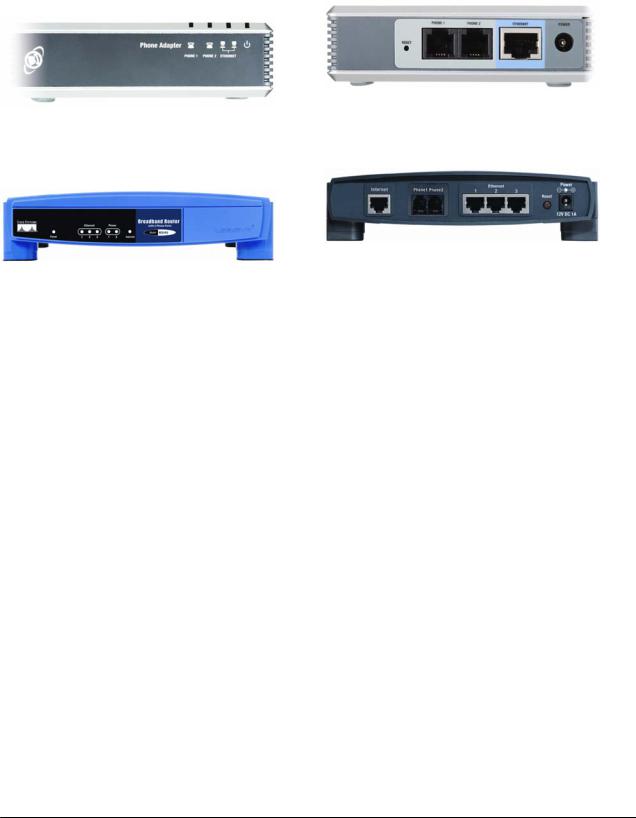
Figure 3 – PAP2 Back
Figure 2 – PAP2 Front
Figure 3 – RT31P2 Front |
Figure 4 – RT31P2 Back |
The PAP2 PHONE ADAPTER has the following interfaces for networking, power and visual status indication:
1. Two (2) RJ-11 Type Analog Telephone Jack Interfaces (Figure 3 , above):
These interfaces accept standard RJ-11 telephone connectors. An Analog touchtone telephone or fax machine may be connected to either interface. If the service supports only one incoming line, the analog telephone or fax machine should be connected to port one (1) of the PHONE ADAPTER. Port one (1) is the outermost telephone port on the PHONE ADAPTER and is labeled “Phone 1.”
2. One Ethernet 10baseT RJ-45 Jack Interface (Figure 3, above):
This interface accepts a standard or crossover Ethernet cable with standard RJ-45 connector. For optimum performance, Linksys recommends that a Category 5 cable or greater be used in conjunction with the PHONE ADAPTER.
The Broadband Router RT31P2 has the following interfaces for networking, power and visual status indication:
1. Two (2) RJ-11 Type Analog Telephone Jack Interfaces (Figure 4, above):
These interfaces accept standard RJ-11 telephone connectors. An Analog touchtone telephone or fax machine may be connected to either interface. If the service supports only one incoming line, the analog telephone or fax machine should be connected to port one (1) of the RT31P2. Port one (1) is the outermost telephone port on the RT31P2 and is labeled “Phone 1.”
2. Four (4) Ethernet 10/100 baseT, three (3) for Local Network and one (1) for Internet, all the 4 ports uses RJ-45 Jack Interface, (Figure 5, above):
This interface accepts a standard or crossover Ethernet cable with standard RJ-45 connector. For optimum performance, Linksys recommends that a Category 5 cable or greater be used in conjunction with the PHONE ADAPTER.
3. LEDs
© 2004 Linksys Proprietary (See Copyright Notice on Page 2) |
18 |

2.1.Phone Adapter LED Status
LED |
Color(s) |
Activity |
Description |
|
|
|
Off |
Power OFF |
|
Power |
Blue |
Blue On |
Power On / Device Ready |
|
Blue Blinking |
Booting / System Self-Test / Firmware upgrade |
|||
|
|
Red On |
POST (Power On Self Test) failure (not bootable) |
|
|
|
or Device malfunction |
||
|
|
|
||
Ethernet |
Blue |
Off |
No Connection on Ethernet |
|
Blue On |
Ethernet Connection established |
|||
|
|
Blue Blinking |
Data Sending / Receiving |
|
Phone 1 / |
Blue |
Off |
Phone is not in use/not provisioned or registered |
|
Blue On |
Registered/provisioned |
|||
Phone 2 |
||||
|
Blue Blinking |
Phone is in use/Incoming Call detected |
||
|
|
2.2.Broadband Router (RT31P2) LED Status
LED |
Color(s) |
Activity |
Description |
|
|
|
|
|
|
|
|
Off |
Power OFF |
|
|
|
Solid Green |
Power On |
|
Power |
Green |
Green |
Booting / System Self-Test / Firmware upgrade |
|
Blinking |
||||
|
|
|
||
|
|
Red On |
POST (Power On Self Test) failure (not bootable) |
|
|
|
or Device malfunction |
||
|
|
|
||
|
|
Off |
No Connection on Ethernet |
|
Ethernet |
Blue |
Solid Green |
Ethernet Connection established |
|
Green |
Data Sending / Receiving |
|||
|
|
|||
|
|
Blinking |
||
|
|
|
||
Phone 1 / |
|
Off |
Phone is not in use/not provisioned or registered |
|
Blue |
Green On |
Registered/provisioned |
||
Phone 2 |
Green |
Phone is in use/Incoming Call detected |
||
|
||||
|
|
Blinking |
||
|
|
|
4. One 5 Volt Power Adapter Interface (Figure 3, above) for PAP2 Phone Adapter and 12 Volt Power Adapter for the Broadband Router (RT31P2)
This interface accepts the PHONE ADAPTER power adapter that came with the unit. Linksys does not support the use of any other power adapters other then the power adapter that was shipped with the PHONE ADAPTER unit or the Broadband Router (RT31P2)
© 2004 Linksys Proprietary (See Copyright Notice on Page 2) |
19 |

Please check to make sure that you have the following package contents:
1.Linksys Phone Adapter Unit or Linksys Broadband Router (RT31P2)
2.Ethernet Cable
3.5 Volt (PAP2) or 12 Volt (RT31P2) Power Adapter
4.CD with User Guide
You will also need:
1.One or Two Analog Touch Tone Telephones (or Fax Machine)
2.Access to an IP Network via an Ethernet Connection
3.One or Two RJ-11 Phone Cable(s).
Please observe the following steps to install the PHONE ADAPTER. From the rear Side of the PHONE ADAPTER:
1.Insert a standard RJ-45 Ethernet cable (included) into the LAN port.2. Insert the power adapter cable into the 5V power adapter cable receptacle. Ensure that the power adapter jack is snugly attached to the PHONE ADAPTER.
2.Insert a standard RJ-11 telephone cable into the Phone 1 port.2. Connect the other end of the cable to an analog telephone or fax machine.
3.Insert a standard RJ-11 telephone cable into the Phone 2 port (Optional)
4.Connect the other end of the cable to an analog telephone or fax machine.
Note: Do not connect RJ-11 telephone cable from the PHONE ADAPTER to the wall jack to prevent any chance of connection to the circuit switched Telco network. You may now insert the plug end of the power adapter into a live power outlet which will power up the PHONE ADAPTER.
3. Software Configuration Mechanisms
The PHONE ADAPTER provides for secure remote provisioning and remote upgrade. Linksys recommends that providers use a secure first-time provisioning mechanism using HTTPS (described in more detail in section 3.2). Subsequent, provisioning is achieved through configuration profiles transferred to the device via TFTP, HTTP or HTTPS. These configuration profiles can be encrypted using AES 256-bit symmetric key encryption using a key configured into the device during the initial HTTPS provisioning stage. As an alternative method for initial configuration, an unprovisioned PHONE ADAPTER can receive an encrypted profile specifically targeted for that device without requiring an explicit key, although this is not as secure as using HTTPS.
The PHONE ADAPTER can be configured to resync its internal configuration state to a remote profile periodically and on power up. An administrator can also remotely trigger a profile resync by sending an authenticated SIP NOTIFY request to the PHONE ADAPTER.
Likewise, remote upgrades are achieved via TFTP, HTTP or HTTPS. The PHONE ADAPTER upgrade logic is capable of automating multi-stage upgrades, in case intermediate upgrades are ever required to reach a future upgrade state from an older release.
General purpose parameters are provided as an additional aid to service providers in managing the provisioning process. The administrator can configure simple comparisons, translations, concatenations, and parameter substitution with the aid of these parameters.
All profile resyncs are attempted only when the PHONE ADAPTER is idle, since they may trigger a software reboot. User intervention is not required to initiate or complete a profile update or firmware upgrade. In general, most configuration changes take effect without requiring a reboot.
© 2004 Linksys Proprietary (See Copyright Notice on Page 2) |
20 |
The PHONE ADAPTER also provides a Web Interface with two-level access (user-level and adminlevel) to configuration parameters. For standalone PHONE ADAPTERS (which contain no router or NAT functionality), an IVR (Interactive Voice Response) interface is also available for configuring basic networking.
3.1.Configuration Profile Formats
The PHONE ADAPTER configuration profile is an XML or binary file with encoded PHONE ADAPTER parameter values and optionally user access permissions for those parameters. By convention, the profile is named with the extension “.cfg” (e.g. pap2.cfg). An administrator can easily generate the XML format and compress and/or encrypt this file with off-the-shelf tools (e.g. gzip, openssl).
The XML configuration file always begins with the top-level element <flat-profile>. Within this element are any number of the configuration elements which are visible in the GUI. The XML tag names are case-sensitive and are identical to the names in the GUI, except that characters other than hyphen, period, underscore, and alphanumeric characters from the GUI are replaced with an underscore in the XML names. For example, User ID(1) becomes <User_ID_1_> .
Empty elements (ex: <element/> ) or missing elements do not change the value already stored in memory. An opening and closing tag (ex: <element></element>) with no included value, deletes the value stored in memory. Standard XML comments and arbitrary whitespace can be included in the file for readability purposes. Note that in XML, less-than ("<") and ampersand ("&") characters within an element must be escaped (using "<" and "&" respectively). Element names in XML are casesensitive.
<flat-profile> <Profile_Rule>https://config.provider.net/linksys/$MA-cfg.xml </Profile_Rule> <Resync_Periodic>86400</Resync_Periodic> <Admin_Passwd>9b4cef5677a129</Admin_Passwd>
<Proxy_1_>sip.provider.net</Proxy_1_> <User_ID_1_>1234567890</User_ID_1_> <Password_1_>YhJ89_Luk4E</Password_1_> <Display_Name_1_>1234567890</Display_Name_1_> <Line_Enable_2_>0</Line_Enable_2_>
</flat-profile>
The Linksys Supplementary Profile Compiler tool (SPC) is provided for compiling a plain-text file containing parameter-value pairs into a binary cfg file which is optionally encrypted. The spc tool is available from Linksys for the Win32 environment (spc.exe), Linux-i386-elf environment (spc-linux- i386-static) and for the OpenBSD environment.
The syntax of the plain-text file accepted by the profile compiler is a series of parameter-value pairs, with the value in double quotes. Each parameter-value pair is followed by a semicolon, e.g. parameter_name “parameter_value”;. If no quoted value is specified for a parameter (or if a parameter specification is missing entirely from the plain-text file) the value of the parameter will remain unchanged in the PHONE ADAPTER.
The SPC syntax also controls the parameter’s user-level access when using the built-in web interface to the PHONE ADAPTER (PAP2-only). An optional exclamation point or question mark, immediately following the parameter name, indicates the parameter should be user read-write or read-only,
© 2004 Linksys Proprietary (See Copyright Notice on Page 2) |
21 |

respectively. If neither mark is present, the parameter is made inaccessible to the user from the web interface. Note that this syntax has no effect on the admin-level access to the parameters.
When using the SPC, a service provider is given full control over which parameters become inaccessible, read-only, or read-write following provisioning of the PHONE ADAPTER.
If the parameter specification is missing entirely from the plain-text file, the user-level access to the parameter will remain unchanged in the PHONE ADAPTER. If the plain-text file contains multiple occurrences of the same parameter-value specification, the last such occurrence overrides any earlier ones.
Parameter names in the plain-text file must match the corresponding names appearing in the PHONE ADAPTER web interface, with the following modifications:
•Inter-word spaces are replaced by underscores ‘_’ (e.g. Multi_Word_Parameter).
•For the PHONE ADAPTER, line and user specific parameters use bracketed index syntax to identify which line or user they refer to (e.g. Line_Enable[1] and Line_Enable[2]).
Comments are delimited by a ‘#’ character up to the end-of-line. Blank lines can be used for readability.
Parameter_name [ ‘?’ | ‘!’ ] [“quoted_parameter_value_string”] ‘;’
Example of plain-text file entries:
# These parameters are for illustration only
Feature_Enable |
! “Enable” ; |
# user read-write |
Another_Parameter |
? “3600” ; |
# user read-only |
Hidden_Parameter |
“abc123” ; |
# user not-accessible |
|
|
|
Some_Entry |
! ; # user read-write, leave value unchanged |
|
Multiple plain text files can be spliced together to generate the source for each CFG file. This is accomplished by the “import” directive: the literal string “import” (placed at the start of a new line) followed by one or more spaces and the file name to splice into the stream of parameter-value pairs. The following example illustrates. File splicing can be nested several files deep.
#base.txt contains . . .
Param1 “base value 1” ; Param2 “base value 2” ;
. . .
#Phone Adapter1234.txt contains . . .
import base.txt
Param1 “new value overrides base” ; Param7 “particular value 7” ;
. . .
© 2004 Linksys Proprietary (See Copyright Notice on Page 2) |
22 |

# The Phone Adapter1234.txt file above is equivalent to . . .
Param1 “base value 1” ; Param2 “base value 2” ;
. . .
Param1 “new value overrides base” ; Param7 “particular value 7” ;
. . .
A sample plain-text file, containing default parameter-value and access settings for the PHONE ADAPTER can be obtained from the profile compiler tool, using the following command-line arguments.
spc –-sample-profile defaults.txt
In both the XML and SPC configuration formats,] Boolean parameter values that evaluate to true are any one of the values {Yes | yes | Enable | enable | 1}. Boolean values that evaluate to false are any one of the values {No | no | Disable | disable | 0}.
3.1.1.Using the Supplemental Profile Compiler
Once a plain-text file has been generated with the desired parameter settings, it needs to be compiled into a binary CFG file. The profile compiler can generate a generic unencrypted CFG file, a targeted CFG file (encrypted for a unique PHONE ADAPTER), a generic key encrypted CFG file, or a targeted and key encrypted CFG file.
A generic CFG file (non-targeted) is accepted as valid by any PHONE ADAPTER device. A targeted CFG file is only accepted as valid by the PHONE ADAPTER device bearing the target MAC address. Targeted CFG files are encrypted with a 128-bit algorithmically generated key, and therefore do not require a key to be issued explicitly. Targeted CFG files provide a basic level of security for remotely locking an otherwise unprovisioned PHONE ADAPTER.
The binary configuration format supports RC4 and AES symmetric key algorithms, with keys of up to 256 bits. The key can be specified explicitly as a hex-string, or it can be generated from a password or a quoted pass-phrase. In the case of passwords and pass-phrases, the internally generated key is 128 bits in length.
The following command-line syntax generates a generic and unencrypted CFG file:
spc pap2.txt pap2.cfg
A targeted CFG file (with basic encryption) is specified by supplying the MAC address of the target device:
spc –-target 000e08aaa010 pap2.txt pap2.cfg
© 2004 Linksys Proprietary (See Copyright Notice on Page 2) |
23 |
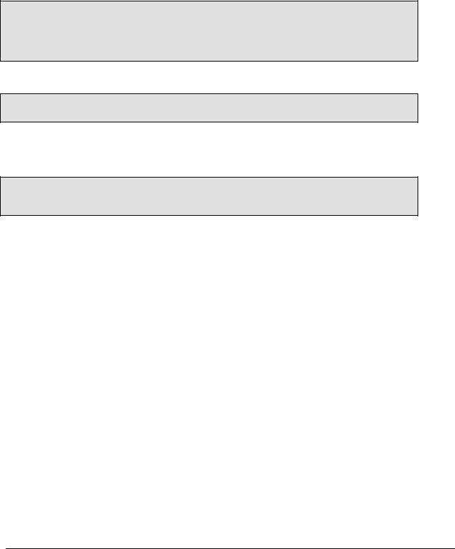
An encrypted CFG file requires either a password (or quoted pass-phrase) or a hex-string. The following lines illustrate command-line invocations for various combinations of keys and algorithms.
spc –-rc4 –-ascii-key apple4sale pap2.txt pap2.cfg spc –-aes –-ascii-key lucky777 pap2.txt pap2.cfg
spc –-aes –-ascii-key “my secret phrase” pap2.txt pap2.cfg spc –-aes –-hex-key 8d23fe7...a5c29 pap2.txt pap2.cfg
A CFG file can be both targeted and key encrypted, as suggested by the following example:
spc –-target 000e08aaa010 –-aes –-hex-key 9a20...eb47 a.txt a.cfg
The status messages printed by spc can be suppressed with the “--quiet” command line option. Or they can be redirected to a file, with the “--log file_name” command line option. In the latter case, the spc command line invocation itself is also printed in the log file, preceded by a timestamp.
spc –-quiet . . .
spc –-log prov.log . . .
3.1.2.Encrypting and Compressing XML configuration files
The Linksys PHONE ADAPTER supports encrypted XML configuration profiles. This can be used for subsequent configuration files stored on or generated by either TFTP or HTTP servers. When used in concert with HTTPS for initial config, this provides complete security, but only uses the HTTPS server for initial enrollment. For example, an example configuration file in XML setup to download an encrypted XML file via HTTP looks like this:
<flat-profile>
<Profile_Rule>[--key $B] http://config.provider.net/linksys/established/$MA.xml </Profile_Rule>
<Resync_Periodic>86400</Resync_Periodic> <GPP_B >9b4cef5677a129</GPP_B> <Admin_Passwd>9b4cef5677a129</Admin_Passwd>
<Proxy_1_>sip.provider.net</Proxy_1_> <User_ID_1_>1234567890</User_ID_1_> <Password_1_>YhJ89_Luk4E</Password_1_> <Display_Name_1_>1234567890</Display_Name_1_> <Line_Enable_2_>0</Line_Enable_2_>
</flat-profile>
An XML configuration file can be encrypted using the openssl command line utility as shown below. (Note that aes encryption is available beginning with OpenSSL versions 0.9.7. OpenSSL is freely available from http://www.openssl.org )
openssl aes-256-cbc -e -in cleartextconfig -out encryptedconfig -k 9b4cef5677a129
© 2004 Linksys Proprietary (See Copyright Notice on Page 2) |
24 |

This utility generates 8-bytes of salt (which is prepended to the encrypted configuration file), and then calculates an Initialization Vector (IV) and an 256-bit encryption key using the key phrase provided on the command line. The TA recognizes the leading characters "Salted__" as a hint to find the salt and decrypt the configuration file.
Linksys XML configuration files can be compressed using the gzip compression algorithm. Gzip is available from http://www.gzip.org .
gzip cleartextconfig.xml
If both compression and encryption are used, the clear text version must be compressed before it is encrypted. The PHONE ADAPTER does not recognize files which are encrypted and then compressed since encrypted files are uncompressible. The Linksys PHONE ADAPTER automatically detects if a file is compressed or encrypted.
3.2.Secure Initial Configuration
Linksys recommends a secure configuration system to providers to protect them from theft of service, account forgery, and denial of service. To that end, Linksys Terminal Adapters are provisioned at the factory with a public key certificate signed by the Linksys certificate authority.
The first step in this process is for the Linksys terminal adapters to use HTTPS to initially contact the configuration server specified in the Profile_Rule. The initial URL can be configured into the TA at manufacturing time for order over a certain size, it can be added during a staging process, or it can be provided via the web interface as described in the next section. The PHONE ADAPTER opens a TCP connection to the initial configuration server, and sends an SSLv2 ClientHello message. The configuration server then presents a server certificate signed by Linksys in a ServerHello message, and requests the certificate of the client. The Terminal Adapter validates the server certificate and provides its client certificate. From the client certificate, the provider is assured of the authenticity of the MAC address, serial number, and model number of the Linksys device which has connected. The terminal adapter will then use an HTTP GET over this TLS secure channel to fetch its initial configuration.
An Apache web server can be setup to perform all the certificate verification automatically as configuration directives. An example configuration is listed below:
<Directory /linksys/secure-setup/> SSLVerifyClient require SSLVerifyDepth 1 SSLRequireSSL
SSLCertificateFile provider-cert-signed-by-linksys.pem SSLCertificateKeyFile provider-private-key.pem SSLCertificateChainFile linksys-cert.pem SSLCACertificateFile linksys-cert.pem
SSLRequire ( %{SSL_CLIENT_VERIFY} eq "SUCCESS" \ and %{SSL_CLIENT_I_DN_O} eq "Linksys" \ and %{SSL_CLIENT_S_DN_O} eq "Linksys" \
and %{SSL_CLIENT_S_DN_CN} eq %{REQUEST_FILENAME}
</Directory>
© 2004 Linksys Proprietary (See Copyright Notice on Page 2) |
25 |

Within this directory, the Apache module mod_ssl verifies the client certificate, and verifies that the MAC address in the certificate corresponds the configuration file it is requesting. Either this directory must contain a configuration file, or a CGI application needs to generate the appropriate config file if that MAC address is configured in your system. (The Apache web server is freely available at http://www.apache.org ).
Once an initial XML configuration file is downloaded from the provider web server, subsequent configuration can be downloaded from the same server. Alternatively, the individual configuration files can be encrypted using AES 256-bit encryption as described previously, using a key that was conveyed in the initial configuration file. These encrypted configuration files then can be downloaded safely using HTTP or TFTP.
Linksys recommends using an encrypted configuration file. In the unlikely event that the private key of a terminal adapter or the Linksys certificate authority is compromised, terminal adapters which have already enrolled with a provider and use an encrypted configuration file would be unaffected by such a compromise.
3.3.Web Interface
The PHONE ADAPTER provides a built-in web server. Configuration and administration can be performed through this convenient web interface.
3.3.1.Web Interface Conventions
The PHONE ADAPTER line uses the following conventions with the web administration capabilities:
oThe PHONE ADAPTER web administration supports two privilege levels: Administrator and User. To use the User privilege, simply point a web browser at the IP address of the PHONE ADAPTER; to use the administrator privilege, use this URL for the PAP2 http://IP_Address_Of_PHONE ADAPTER/admin/, and this URL for the RT31P2: http://IP_Address_Of_PHONE ADAPTER/Voice_adminPage.htm . The default IP address for the LAN interface of the RT31P2 is 192.168.15.1. See the next section for more information about administration privileges.
oThe PHONE ADAPTER supports Internet Explorer 5.5 and above and Netscape 7.0 and above.
oThe web configuration pages can be password protected. See 3.3.2 for more information about password protect.
o The user name of web Administrator is : admin o The user name of web User is : user
o Note: The user names for both administrator and User are fixed and cannot be changed.
o After making changes to PHONE ADAPTER configuration parameters, pressing “Submit All Changes” button will apply all the changes and if necessary, automatically reboot the device. Multiple changes may be made on multiple page tabs of the web interface at the same time. Pressing “Submit All Changes” will apply all the modifications.
Important Note: switching between page tabs won’t apply the changes to PHONE ADAPTER, The only way to apply the changes is to press the “Submit All Changes” button.
oIf the “Undo All Changes” button is clicked, any modifications to profile parameters on any and all pages will be reset back to their original values before modification.
© 2004 Linksys Proprietary (See Copyright Notice on Page 2) |
26 |

NOTE: Pressing the “Undo All Changes” has no effect on the PHONE ADAPTER; it will only reset the values on the web page.
3.3.2.Administration Privileges
The PHONE ADAPTER supports two levels of administration privileges: Administrator and User, both privileges can be password protected. Important note: by factory default, there are no passwords assigned for both Administrator and User.
The Administrator has the privilege to modify all the web profile parameters and can also modify the passwords of both Administrator and User. A User only has the privilege to access part of the web profile parameters; the parameter group that User can access is specified by the Administrator, which can only be done through provisioning.
To access the Administrator level privilege, use the URL for your model number as described in the previous section. If the password has been set for Administrator, the browser will prompt for authentication. The username for Administrator is “admin” and cannot be changed.
To access the User level privilege, use URL: http://IP_Address_Of_PHONE ADAPTER/. If the password has been set for User, the browser will prompt for User authentication. The username for User is “user” and cannot be changed.
When browsing Administrator pages, one can switch to User privileges by click the link “User Login”. (Note: if User password was set, the browser will prompt for User authentication when you click “User Login” link). On the other side, from the User pages you can switch to Administrator privilege by clicking the link “Admin Login.” Authentication is needed if Administrator password has been set.
Warning: Switching between the User and Administrator will discard the uncommitted changes that have already been made on the web pages.
3.3.3.Basic and Advanced Views
The PAP2 web configuration interface provides a Basic and an advanced view from which the various configuration parameters can be accessed. The PHONE ADAPTER Provisioning tab is only visible from the Advanced Administrator view of the web interface.
Warning: Switching between the basic and advanced view will discard the uncommitted changes that have already been made on the web pages.
3.4.Functional Configuration URLs
The web interface of the PHONE ADAPTER supports several functions through special URLs: Upgrade, Reboot, Profile Resync, and Factory Reset. Administrator privilege is needed for these functions.
Note that on the RT31P2, these URLs are only accessible from the LAN interface, unless the Admin_Passwd has been set and the Enable_Web_Admin_Access parameter is set.
3.4.1.Upgrade URL
Through upgrade URL you can upgrade the PHONE ADAPTER to a firmware specified by the URL. Note: If the value of “upgrade enable” parameter in Provisioning tab is no, you cannot upgrade the PHONE ADAPTER even if the web page tells you that the upgrade will be done when it is not in use. See 4.2.1 to get more information on firmware upgrade.
The syntax of Upgrade URL is: http://<PAP2-ip-addr>/upgrade?[protocol://][server-name[:port]][/firmware-pathname] or
© 2004 Linksys Proprietary (See Copyright Notice on Page 2) |
27 |

http://<PAP2-ip-addr>/admin/upgrade?[protocol://][server-name[:port]][/firmware-pathname]
If no protocol is specified, TFTP is assumed. Note: Only TFTP is supported in the current release. If no server-name is specified, the host that requests the URL is used as server-name.
If no port specified, default port of the protocol is used. (69 for TFTP, 80 for http, 443 for HTTPS)
The “firmware-pathname” is typically the file name of the PHONE ADAPTER binary located in the root directory of the TFTP server. If no firmware-pathname is specified, “/Phone Adapter.bin” is assumed.
For example: http://192.168.2.217/upgrade?tftp://192.168.2.251/PAP2.bin
3.4.2.Resync URL
Through Resync URL you can force the PHONE ADAPTER to do a resync to a profile specified in the URL.
Note: The PHONE ADAPTER will resync only when it is idle. The syntax of Resync URL is:
http://<Phone Adapter-ip-addr>/resync?[[protocol://][server-name[:port]]/profile-pathname]
If no parameter follows “/resync?”, the profile rule setting in provisioning is used. See 4.2 for detailed information about profile rule in provisioning
If no protocol is specified, TFTP protocol is assumed. Note: Only TFTP is supported in the current release.
If no server-name is specified, the host that requests the URL is used as server-name.
If no port specified, default port of the protocol is used – 69 for TFTP, 80 for http, 443 for HTTPS. The profile-path is the path to the new profile to resync with.
For example: http://192.168.2.217/upgrade?tftp://192.168.2.251/PAP2.scf
3.4.3.Reboot URL
Through the Reboot URL, you can reboot the PHONE ADAPTER.
Note: Upon request, the PHONE ADAPTER will reboot only when it is idle.
The Reboot URL is: http://<Phone Adapter-ip-addr>/admin/reboot
3.4.4.Factory Reset URL
Through the Reset URL, you can perform a factory reset of the PHONE ADAPTER. Note: Upon request, the PHONE ADAPTER will reset and then reboot only when it is idle. The Reset URL is: http://<Phone Adapter-ip-addr>/admin/reset
© 2004 Linksys Proprietary (See Copyright Notice on Page 2) |
28 |

3.5.Configuration via the IVR (PAP2 only)
Administrators and/or users can check (read) and set (write) basic network configuration settings via a touchtone telephone connected to one of the RJ-11 phone ports of the PAP2 model PHONE ADAPTER.
Please Note:
Service Providers offering service using the PHONE ADAPTER may restrict, protect or turn off certain aspects of the unit’s IVR and web configuration capabilities.
The Interactive Voice Response (IVR) capabilities of the PHONE ADAPTER are designed to give the administrator and/or user basic read/write capabilities such that the unit can attain basic IP network connectivity and the more advanced browser-based configuration menu may be accessed.
1. The PHONE ADAPTER IVR uses the following conventions: By factory default there is no password and no password authentication is prompted for all the IVR settings. If administrator password is set, password authentication will be prompted for certain IVR settings. See 3.4.2 for detailed information about administrator password.
To input the password using the phone keypad, the following translation convention applies: o To input: A, B, C, a, b, c -- press ‘2’
o To input: D, E, F, d, e, f -- press ‘3’ o To input: G, H, I, g, h, i -- press ‘4’ o To input: J, K, L, j, k, l -- press ‘5’
o To input: M, N, O, m, n, o -- press ‘6’
o To input: P, Q, R, S, p, q, r, s -- press ‘7’ o To input: T, U, V, t, u, v -- press ‘8’
o To input: W, X, Y, Z, w, x, y, z -- press ‘9’
o To input all other characters in the administrator password, press ‘0’ Note: This translation convention only applies to the password input.
For example: to input password “test#@1234” by phone keypad, you need to press the following sequence of digits: 8378001234.
2.After entering a value, press the # (pound) key to indicate end of input. o To Save value, press ‘1’
o To Review the value, press ‘2’ o To Re-enter the value, press ‘3’
o To Cancel the value entry and return to the main configuration menu, press ‘*’ (star) Notes:
o The final ‘#’ key won’t be counted into value.
oSaved settings will take effect when the telephone is hung-up and if necessary, the PHONE ADAPTER will automatically reboot.
© 2004 Linksys Proprietary (See Copyright Notice on Page 2) |
29 |
3.After one minute of inactivity, the unit times out. The user will need to re-enter the configuration menu from the beginning by pressing * * * *.
4.If, while entering a value (like an IP address) and you decide to exit without entering any changes, you may do so by pressing the * (star) key twice within a half second window of time. Otherwise, the entry of the * (star) key will be treated as a dot (decimal point).
Example: To enter IP address, use numbers 0 – 9 on the telephone key pad and use the * (star) key to enter a decimal point.
To enter the following IP address value: 192.168.2.215
A.Use the touchtone key pad to enter: 192*168*2*215#
B.When prompted, enter 1 to save setting to configuration.
C.Hang-up the phone to cause setting to take effect.
- or -
D. Enter the value of the next setting category to modify . . .
5. Hang-up the phone to cause all settings to take effect.
PHONE ADAPTER Interactive Voice Response (IVR) Menu:
|
IVR Action |
IVR Menu Choice |
Parameter(s) |
Notes: |
|
|
Enter IVR Menu |
* * * * |
None |
Ignore SIT or other tones |
|
|
|
|
until you hear, “Linksys |
|
|
|
|
|
|
configuration menu. |
|
|
|
|
|
Please enter option |
|
|
|
|
|
followed by the pound key |
|
|
|
|
|
or hang-up to exit.” |
|
|
Exit IVR Menu |
3948 |
None |
|
|
|
Check DHCP |
100 |
None |
IVR will announce if DHCP |
|
|
|
|
|
in enabled or disabled. |
|
|
Enable/Disable DHCP |
101 |
Enter 1 to enable |
Requires Password |
|
|
|
|
Enter 0 to disable |
|
|
|
|
|
|
|
|
|
Check IP Address |
110 |
None |
IVR will announce the |
|
|
|
|
|
current IP address of |
|
|
|
|
|
PHONE ADAPTER. |
|
|
Set Static IP Address |
111 |
Enter IP address |
DHCP must be “Disabled” |
|
|
|
|
using numbers on |
otherwise you will hear, |
|
|
|
|
the telephone key |
“Invalid Option,” if you try |
|
|
|
|
pad. Use the * |
to set this value. |
|
|
|
|
(star) key when |
Requires Password |
|
|
|
|
entering a decimal |
|
|
|
|
|
|
|
|
|
|
|
point. |
|
|
|
|
|
|
|
|
|
Check Network Mask |
120 |
None |
IVR will announce the |
|
|
|
|
|
current network mask of |
|
|
|
|
|
||
|
© 2004 Linksys Proprietary (See Copyright Notice on Page 2) |
30 |
|
||
 Loading...