


 Loading...
Model DPC2434 and EPC2434 VoIP
Wireless Home Gateway User Guide
In This Document
IMPORTANT SAFETY INSTRUCTIONS ............................................................... |
3 |
FCC Compliance ......................................................................................................... |
9 |
Introduction............................................................................................................... |
10 |
What's In the Carton?............................................................................................... |
12 |
Front Panel Description ........................................................................................... |
14 |
Back Panel Description ............................................................................................ |
16 |
Where Is the Best Location for My Wireless Home Gateway?........................... |
20 |
What Are the System Requirements for Internet Service?.................................. |
21 |
How Do I Set Up My High-Speed Internet Access Account? ............................ |
22 |
How Do I Connect My Devices to Use the Internet?........................................... |
23 |
How Do I Configure TCP/IP Protocol? ................................................................ |
25 |
How Do I Install USB Drivers? ............................................................................... |
28 |
What Are the Requirements for Ethernet Network Devices? ............................ |
29 |
How Do I Select and Place Ethernet Network Devices? ..................................... |
30 |
How Do I Connect Ethernet Network Devices?................................................... |
31 |
What Are the Requirements for USB Network Devices?.................................... |
33 |
How Do I Select and Place USB Network Devices?............................................. |
34 |
How Do I Connect USB Network Devices? .......................................................... |
35 |
How Do I Troubleshoot My Internet Service Installation?................................. |
37 |
What Are the Requirements for Wireless Network Devices? ............................ |
40 |
How Do I Select and Place Wireless Network Devices? ..................................... |
41 |
How Do I Install Wireless Network Devices? ...................................................... |
42 |
How Do I Use My Wireless Home Gateway for Telephone Service? ............... |
44 |
Where Do I Place My Wireless Home Gateway for Telephone Service?.......... |
45 |
What Are the Requirements for Telephone Service?........................................... |
46 |
How Do I Install the Modem for Telephone Service? ......................................... |
47 |
How Do I Maintain the Batteries? .......................................................................... |
50 |
How Do I Mount the Modem on a Wall? (Optional)........................................... |
52 |
How Do I Configure the Wireless Home Gateway?............................................ |
56 |
Telephone Service Frequently Asked Questions................................................ |
131 |
Access Basic Gateway Information ...................................................................... |
133 |
Having Difficulty? .................................................................................................. |
136 |
Tips for Improved Performance ........................................................................... |
139 |
Front Panel LED Status Indicator Functions....................................................... |
140 |
Notices...................................................................................................................... |
143 |
For Information....................................................................................................... |
144 |
2 |
4011350 Rev C |
IMPORTANT SAFETY INSTRUCTIONS
IMPORTANT SAFETY INSTRUCTIONS
Notice to Installers
The servicing instructions in this notice are for use by qualified service personnel only. To reduce the risk of electric shock, do not perform any servicing other than that contained in the operating instructions, unless you are qualified to do so.
20070112 SysInstaller 820 English
Notice à l’attention des installateurs de réseaux câblés
Les instructions relatives aux interventions d’entretien, fournies dans la présente notice, s’adressent exclusivement au personnel technique qualifié. Pour réduire les risques de chocs électriques, n’effectuer aucune intervention autre que celles décrites dans le mode d'emploi et les instructions relatives au fonctionnement, à moins que vous ne soyez qualifié pour ce faire.
|
20070112 SysInstaller 820 French |
4011350 Rev C |
3 |

IMPORTANT SAFETY INSTRUCTIONS
Mitteilung für CATV-Techniker
Die in dieser Mitteilung aufgeführten Wartungsanweisungen sind ausschließlich für qualifiziertes Fachpersonal bestimmt. Um die Gefahr eines elektrischen Schlags zu reduzieren, sollten Sie keine Wartungsarbeiten durchführen, die nicht ausdrücklich in der Bedienungsanleitung aufgeführt sind, außer Sie sind zur Durchführung solcher Arbeiten qualifiziert.
20070112 SysInstaller 820 German
Aviso a los instaladores de sistemas CATV
Las instrucciones de reparación contenidas en el presente aviso son para uso exclusivo por parte de personal de mantenimiento cualificado. Con el fin de reducir el riesgo de descarga eléctrica, no realice ninguna otra operación de reparación distinta a las contenidas en las instrucciones de funcionamiento, a menos que posea la cualificación necesaria para hacerlo.
20070112 SysInstaller 820 Spanish
4 |
4011350 Rev C |

IMPORTANT SAFETY INSTRUCTIONS
Read These Instructions
Keep These Instructions Heed All Warnings Follow All Instructions
Power Source Warning
A label on this product indicates the correct power source for this product. Operate this product only from an electrical outlet with the voltage and frequency indicated on the product label. If you are uncertain of the type of power supply to your home or business, consult your service provider or your local power company.
The AC inlet on the unit must remain accessible and operable at all times.
Ground the Product
WARNING: Avoid electric shock and fire hazard! Do not defeat the safety purpose of the polarized or grounding-type plug. A polarized plug has two blades with one wider than the other. A grounding-type plug has two blades and a third grounding prong.
The wide blade or the third prong is provided for your safety. If the provided plug does not fit into your outlet, consult an electrician for replacement of the obsolete outlet.
If this product connects to coaxial cable wiring, be sure the cable system is grounded (earthed). Grounding provides some protection against voltage surges and built-up static charges.
Protect the Product from Lightning
For added protection, unplug this apparatus during lightning storms or when unused for long periods of time. In addition to disconnecting the AC power from the wall outlet, disconnect the signal inputs.
Verify the Power Source from the On/Off Power Light
When the on/off power light is not illuminated, the apparatus may still be connected to the power source. The light may go out when the apparatus is turned off, regardless of whether it is still plugged into an AC power source.
Eliminate AC Mains Overloads
WARNING: Avoid electric shock and fire hazard! Do not overload AC mains, outlets, extension cords, or integral convenience receptacles. For products that require battery power or other power sources to operate them, refer to the operating instructions for those products.
4011350 Rev C |
5 |

IMPORTANT SAFETY INSTRUCTIONS
Prevent Power Cord Damage
Protect the power cord from being walked on or pinched, particularly at plugs, convenience receptacles, and the point where the cord exits from the apparatus.
Handling Optional, Rechargeable Battery
This product may contain a rechargeable Lithium-Ion battery to provide stand-by operation in the event of an AC power failure. Heed the following warning and see the instructions later in this guide for handling, replacing, and disposing of the battery.
WARNING: There is danger of explosion if the battery is mishandled or incorrectly replaced. Replace only with the same type of battery. Do not disassemble it or attempt to recharge it outside the system. Do not crush, puncture, dispose of in fire, short the external contacts, or expose to water or other liquids. Dispose of the battery in accordance with local regulations and instructions from your service provider.
Handling Disposable Batteries
This product may contain disposable batteries.
Heed the preceding warning about explosion and disposal issues, and follow the Safety and Disposal instructions below.
Safety
Insert batteries correctly. There may be a risk of explosion if the batteries are incorrectly inserted.
Do not attempt to recharge ‘disposable’ or ‘non-reusable’ batteries.
Please follow instructions provided for charging ‘rechargeable’ batteries.
Replace batteries with the same or equivalent type that we recommend.
Do not expose batteries to temperatures above 100°C (212°F).
Disposal
The batteries may contain substances that could be harmful to the environment.
Recycle or dispose of batteries in accordance with the battery manufacturer’s instructions and local/national disposal and recycling regulations.
The batteries may contain perchlorate, a known hazardous substance, so special handling and disposal of this product might be necessary. For more information about perchlorate and best management practices for perchlorate-containing substance, see www.dtsc.ca.gov/hazardouswaste/perchlorate
Provide Ventilation and Select a Location
Remove all packaging material before applying power to the product.
Do not block any ventilation openings. Install in accordance with the manufacturer's instructions.
6 |
4011350 Rev C |

IMPORTANT SAFETY INSTRUCTIONS
Do not place this apparatus on a bed, sofa, rug, or similar surface.
Do not place this apparatus on an unstable surface.
Do not install near any heat sources such as radiators, heat registers, stoves, or other apparatus (including amplifiers) that produce heat.
Do not install this apparatus in an enclosure, such as a bookcase or rack, unless the installation provides proper ventilation.
Do not place entertainment devices (such as VCRs or DVDs), lamps, books, vases with liquids, or other objects on top of this product.
Protect from Exposure to Moisture and Foreign Objects
Do not use this apparatus near water.
WARNING: Avoid electric shock and fire hazard! Do not expose this product to liquids, rain, or moisture.
WARNING: Avoid electric shock and fire hazard! Unplug this product before cleaning. Clean only with a dry cloth. Do not use a liquid cleaner or an aerosol cleaner. Do not use a magnetic/static cleaning device (dust remover) to clean this product.
WARNING: Avoid electric shock and fire hazard! Never push objects through the openings in this product. Foreign objects can cause electrical shorts that can result in electric shock or fire.
Accessories Warning
WARNING: Avoid electric shock and fire hazard! Only use attachments/accessories specified by your service provider or the manufacturer.
Service Warnings
WARNING: Avoid electric shock! Do not open the cover of this product. Opening or removing the cover may expose you to dangerous voltages. If you open the cover, your warranty will be void. This product contains no user-serviceable parts. Refer all servicing to qualified service personnel.
Servicing is required when the apparatus has been damaged in any way, such as a power-supply cord or plug is damaged, liquid has been spilled or objects have fallen into the apparatus, the apparatus has been exposed to rain or moisture, does not operate normally, or has been dropped.
4011350 Rev C |
7 |

IMPORTANT SAFETY INSTRUCTIONS
Check Product Safety
Upon completion of any service or repairs to this product, the service technician must perform safety checks to determine that this product is in proper operating condition.
Protect the Product When Moving It
Always disconnect the power source when moving the apparatus or connecting or disconnecting cables.
WARNING: Avoid personal injury and damage to this product! Use only with the cart, stand, tripod, bracket, or table specified by the manufacturer or sold with the apparatus. When a cart is used, use caution when moving the cart / apparatus combination to avoid injury from tip-over.
20080402 Modem Cable with Recharge Battery
8 |
4011350 Rev C |
FCC Compliance
FCC Compliance
United States FCC Compliance
This device has been tested and found to comply with the limits for a Class B digital device, pursuant to part 15 of the FCC Rules. These limits are designed to provide reasonable protection against such interference in a residential installation. This equipment generates, uses, and can radiate radio frequency energy. If not installed and used in accordance with the instructions, it may cause harmful interference to radio communications. However, there is no guarantee that interference will not occur in a particular installation. If this equipment does cause harmful interference to radio or television reception, which can be determined by turning the equipment OFF and ON, the user is encouraged to try to correct the interference by one or more of the following measures:
Reorient or relocate the receiving antenna.
Increase the separation between the equipment and receiver.
Connect the equipment into an outlet on a circuit different from that to which the receiver is connected.
Consult the cable company or an experienced radio/television technician for help.
Any changes or modifications not expressly approved by Scientific-Atlanta, Inc., could void the user's authority to operate the equipment.
The information shown in the FCC Declaration of Conformity paragraph below is a requirement of the FCC and is intended to supply you with information regarding the FCC approval of this device. The phone numbers listed are for FCC-related questions only and not intended for questions regarding the connection or operation for this device. Please contact your cable service provider for any questions you may have regarding the operation or installation of this device.
 Declaration of Conformity
This device complies with Part 15 of FCC |
VoIP Wireless Home Gateway |
Rules. Operation is subject to the following two |
Models: DPC2434 and EPC2434 |
conditions: 1) the device may not cause |
Manufactured by: |
harmful interference, and 2) the device must |
Scientific-Atlanta, Inc. |
accept any interference received, including |
5030 Sugarloaf Parkway |
interference that may cause undesired |
Lawrenceville, Georgia 30044 USA |
operation. |
Telephone: 770-236-1077 |
|
|
Canada EMI Regulation
This Class B digital apparatus complies with Canadian ICES-003.
Cet appareil numérique de la class B est conforme à la norme NMB-003 du Canada.
20060628 FCC Standard
4011350 Rev C |
9 |
Introduction
Introduction
Welcome to the exciting world of high-speed Internet and high-quality digital telephone service. Your new Model DPC2434 or EPC2434 Voice-over-Internet Protocol (VoIP) Wireless Home Gateway is a cable modem that meets industry standards for high-speed data connectivity along with reliable digital telephone service. The DPC2434 and EPC2434 wireless home gateways deliver data, voice and wired (Ethernet) or wireless gateway capabilities to connect a variety of devices in the home or small office and support high-speed data access and VoIP services, all in one device. With a DPC2434 or EPC2434 wireless home gateway, your Internet enjoyment, home and business communications, and personal productivity will surely soar.
This guide provides procedures and recommendations for placing, installing, configuring, operating, and troubleshooting your DPC2434 or EPC2434 wireless home gateway for high-speed Internet and digital telephone service for your home or office. Refer to the appropriate section in this guide for the specific information you need for your situation. Contact your service provider for more information about subscribing to these services.
Benefits and Features
Your new DPC2434 or EPC2434 wireless home gateway offers the following outstanding benefits and features:
|
Features an embedded media terminal adapter (EMTA) supporting two-line |
|
voice services |
|
Provides a high-speed broadband Internet connection that energizes your online |
|
experience, such as providing hassle-free downloading and sharing files and |
|
photos with your family and friends |
|
Includes four 10/100BASE-T Ethernet ports and a USB port to provide |
|
connectivity for high-speed data services or to other Internet devices |
|
Assures a broad range of interoperability with most service providers by |
|
complying with Data Over Cable System Interface Specifications (DOCSIS®) 1.0, |
|
1.1, and 2.0 standards along with PacketCable™ 1.0 specifications to deliver |
|
high-end performance and reliability |
|
Includes two RJ-11 telephony ports for connecting conventional telephones or |
|
fax machines |
|
Allows you to attach multiple devices in your home or office to the wireless |
|
home gateway for high-speed wired and wireless networking and sharing of |
|
files and folders without first copying them onto a CD or diskette |
|
Optional model includes up to two internal Lithium-Ion cartridge-style batteries |
|
for convenient and long-lasting backup power |
10 |
4011350 Rev C |
Introduction
Features Plug and Play operation for easy set up and installation
Provides parental control and advanced firewall technology
Utilizes an attractive compact design that allows for vertical, horizontal, or wallmount placement
Allows automatic software upgrades by your service provider
4011350 Rev C |
11 |
What's In the Carton?
What's In the Carton?
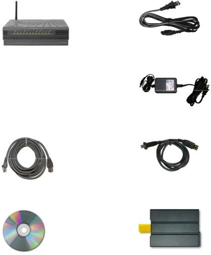
When you receive your wireless home gateway, you should check the equipment and accessories to verify that each item is in the carton and that each item is undamaged. The carton contains the following items:
One of the following DPC2434 or EPC2434 VoIP Wireless Home Gateway versions:
With or without battery backup capability
With internal or external power supply
One AC power cord (models with internal power supply)
or
One Ethernet cable (CAT5/RJ-45)
One CD-ROM containing the user's guide and the USB drivers
One power adapter (models requiring external power supply)
One USB cable (not included with some models)
Lithium Ion cartridge battery (not included with some models)
If any of these items are missing or damaged, please contact your service provider for assistance.
12 |
4011350 Rev C |
What's In the Carton?
Notes:
You will need an optional cable signal splitter and additional standard RF coaxial cables if you want to connect a VCR, a Digital Home Communications Terminal (DHCT) or a set-top converter, or a TV to the same cable connection as your wireless home gateway.
Cables and other equipment needed for telephone service must be purchased separately. Contact your service provider to inquire about the equipment and cables you need for telephone service.
4011350 Rev C |
13 |
Front Panel Description
Front Panel Description
The front panel of your wireless home gateway provides LED status indicators that indicate how well and at what state your wireless home gateway is operating. See
Front Panel LED Status Indicator Functions (on page 140), for more information on front panel LED status indicator functions.
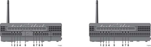
DPC2434 or EPC2434 |
DPC2434 or EPC2434 |
(with battery backup capability) |
(without battery backup capability) |
1POWER—On indicates that AC power is being applied to the wireless home gateway
2DS—On indicates that the wireless home gateway is receiving data from the cable network
3US—On indicates that the wireless home gateway is sending data to the cable network
4ONLINE—On indicates that the wireless home gateway is registered on the network and fully operational
5LAN1 - LAN4/USB—On indicates that an Ethernet/USB connection is present and blinking indicates that Ethernet/USB data is being transferred between a PC and the wireless home gateway
6WIRELESS—On indicates that the wireless access point is enabled and operational and blinking indicates that wireless data is being transferred between a PC and the wireless home gateway. The LED is off when the wireless access point is disabled by the user
7TEL1—On indicates that telephony service is enabled. Blinking indicates that line 1 is in use
8TEL2—On indicates that telephony service is enabled. Blinking indicates that line 2 is in use
14 |
4011350 Rev C |
Front Panel Description
9 BATTERY (optional model only)—On indicates that the battery is charged. Blinking indicates that the battery charge is low. Off indicates that the unit operating from battery power, that the battery charge is depleted, or the battery is defective or missing
Notes:
After the wireless home gateway is successfully registered on the network, the POWER (LED 1), DS (LED2), US (LED3), and ONLINE (LED 4) LEDs illuminate continuously to indicate that the cable modem is active and fully operational.
The wireless home gateway high-speed data operation is disabled when operating on battery power and only the telephone service is active.
LEDs may behave differently when the wireless home gateway is running on battery power (without AC power). Most LEDs are disabled if the unit is operating on battery power. In this mode, the POWER LED blinks to indicate that the unit is operating under battery power.
The gateway should only run on battery power when AC power has failed. If the POWER LED indicates that the unit is running on battery power but the AC power has not failed, verify that the power cord is plugged into a working AC outlet.
4011350 Rev C |
15 |
Back Panel Description
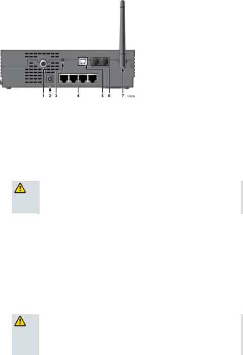
Back Panel Description
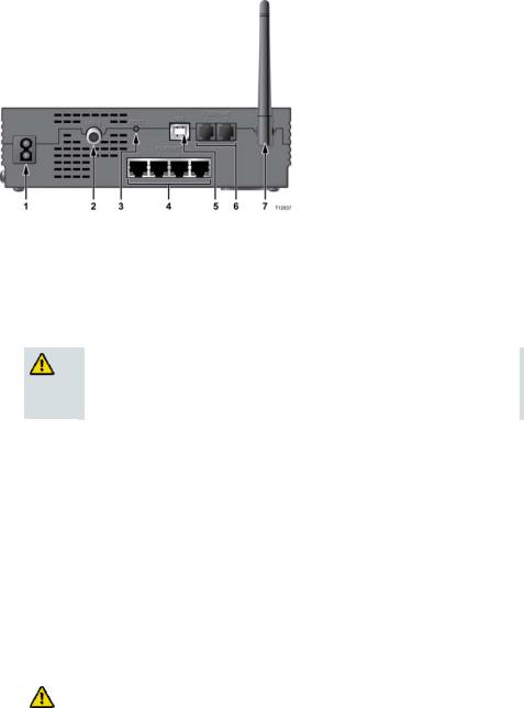
The following illustrations show the description and function of the back panel components on the DPC2434 or EPC2434.
Internal Power Supply Model
DPC2434 or EPC2434 (with internal power supply)
Important: Do not connect any single PC to both the Ethernet and USB ports at the same time. Your wireless home gateway will not function properly.
1 POWER—Connects the wireless home gateway to the AC power cord that is provided with your wireless home gateway
CAUTION:
Avoid damage to your equipment. Only use the AC power cord that is provided with your wireless home gateway.
2CABLE—F-connector connects to an active cable signal from your service provider
3RESET
Soft Reset—Pressing the Reset switch momentarily (less than 1 second) initiates a “soft” reset of the wireless home gateway. A soft reset causes the gateway to restart and to re-register on the network. A soft reset will not erase your personal settings configured in the gateway.
Factory Reset—Activating this switch resets the EMTA. Pressing the reset switch and holding it in for more than ten seconds resets the device to factory default values and restarts the EMTA. A factory reset will reset all settings to the original factory settings and will erase all your personal settings configured in the gateway.
|
CAUTION: |
|
|
The Reset button is for maintenance purposes only. Do not use |
|
|
unless instructed to do so by your service provider. Doing so |
|
|
may cause you to lose any cable modem settings you have |
|
|
selected. |
|
16 |
|
4011350 Rev C |
Back Panel Description
4ETHERNET—Four RJ-45 Ethernet ports connect to the Ethernet port on your PC or your home network
5USB—USB 2.0 port connects to the USB port on your PC
6TELEPHONE 1 and 2—RJ-11 telephone ports connect to home telephone wiring to conventional telephones or fax machines
7ANTENNA—Provides a communication connection for the built-in wireless access point (WAP) to allow wireless devices to communicate with the modem
4011350 Rev C |
17 |
Back Panel Description
External Power Supply Model
DPC2434 or EPC2434 (with external power supply)
Important: Do not connect any single PC to both the Ethernet and USB ports at the same time. Your wireless home gateway will not function properly.
1CABLE—F-connector connects to an active cable signal from your service provider
215VDC—Connects the wireless home gateway to the AC power adapter that is provided with your wireless home gateway
CAUTION:
Avoid damage to your equipment. Only use the power supply that is provided with your wireless home gateway.
3RESET
Soft Reset—Pressing the Reset switch momentarily (less than 1 second) initiates a “soft” reset of the wireless home gateway. A soft reset causes the gateway to restart and to re-register on the network. A soft reset will not erase your personal settings configured in the gateway.
Factory Reset—Activating this switch resets the EMTA. Pressing the reset switch and holding it in for more than ten seconds resets the device to factory default values and restarts the EMTA. A factory reset will reset all settings to the original factory settings and will erase all your personal settings configured in the gateway.
CAUTION:
The Reset button is for maintenance purposes only. Do not use unless instructed to do so by your service provider. Doing so may cause you to lose any cable modem settings you have selected.
4 ETHERNET—Four RJ-45 Ethernet ports connect to the Ethernet port on your PC or your home network
18 |
4011350 Rev C |
Back Panel Description
5USB—USB 2.0 port connects to the USB port on your PC
6TELEPHONE 1 and 2—RJ-11 telephone ports connect to home telephone wiring to conventional telephones or fax machines
7ANTENNA—Provides a communication connection for the built-in wireless access point (WAP) to allow wireless devices to communicate with the wireless home gateway
4011350 Rev C |
19 |
Where Is the Best Location for My Wireless Home Gateway?
Where Is the Best Location for My Wireless Home Gateway?
The ideal location for your wireless home gateway is where it has access to outlets and other devices. Think about the layout of your home or office, and consult with your service provider to select the best location for your wireless home gateway.
Read this user guide thoroughly before you decide where to place your wireless home gateway.
Consider these recommendations:
Position your PC and wireless home gateway so that they are located near an AC power outlet.
Position your PC and wireless home gateway so that they are located near an existing cable input connection to eliminate the need for an additional cable outlet. There should be plenty of room to guide the cables away from the modem and the PC without straining or crimping them.
Airflow around the wireless home gateway should not be restricted.
Choose a location that protects the wireless home gateway from accidental disturbance or harm.
20 |
4011350 Rev C |
What Are the System Requirements for Internet Service?
What Are the System Requirements for Internet Service?
To ensure that your wireless home gateway operates efficiently for high-speed Internet service, verify that all of the Internet devices on your system meet or exceed the following minimum hardware and software requirements.
Note: You will also need an active cable input line and an Internet connection.
Minimum System Requirements for a PC
A PC with a Pentium MMX 133 processor or greater
32 MB of RAM
Web browsing software
CD-ROM drive
Minimum System Requirements for Macintosh
MAC OS 7.5 or later
32 MB of RAM
System Requirements for an Ethernet Connection
A PC with Microsoft Windows 95 operating system (or later) with TCP/IP protocol installed, or an Apple Macintosh computer with TCP/IP protocol installed
An active 10/100BASE-T Ethernet network interface card (NIC) installed
System Requirements for a USB Connection
A PC with Microsoft Windows 98SE, ME, 2000, XP, or Vista operating system
A master USB port installed in your PC
4011350 Rev C |
21 |
How Do I Set Up My High-Speed Internet Access Account?
How Do I Set Up My High-Speed Internet Access Account?
Before you can use your wireless home gateway, you need to have a high-speed Internet access account. If you do not have a high-speed Internet access account, you need to set up an account with your local service provider. Choose one of the two options in this section.
I Do Not Have a High-Speed Internet Access Account
If you do not have a high-speed Internet access account, your service provider will set up your account and become your Internet Service Provider (ISP). Internet access enables you to send and receive email, access the World Wide Web, and receive other Internet services.
You will need to give your service provider the following information:
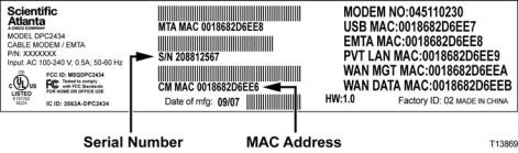
The serial number of the modem
The Media Access Control (MAC) address of the modem
These numbers appear on a bar code label located on the wireless home gateway. The serial number consists of a series of alphanumeric characters preceded by S/N. The MAC address consists of a series of alphanumeric characters preceded by CM MAC. The following illustration shows a sample bar code label.
Write down these numbers in the space provided here.
Serial Number _______________________
MAC Address ________________________
I Already Have an Existing High-Speed Internet Access Account
If you have an existing high-speed Internet access account, you must give your service provider the serial number and the MAC address of the wireless home gateway. Refer to the serial number and MAC address information listed previously in this section.
Note: You may not be able to continue to use your existing email account with your wireless home gateway. Contact your service provider for more information.
22 |
4011350 Rev C |
How Do I Connect My Devices to Use the Internet?
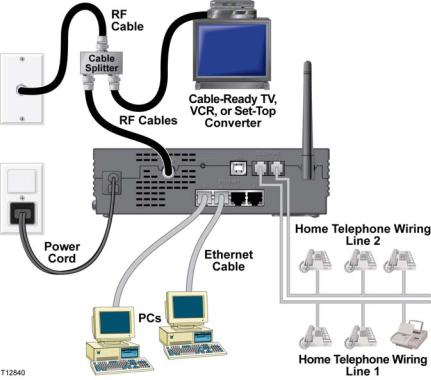
How Do I Connect My Devices to Use the Internet?
You can use your wireless home gateway to access the Internet, and you can share that Internet connection with other Internet devices in your home or office. Sharing one connection among many devices is called networking.
Connecting and Installing Internet Devices
You must connect and install your wireless home gateway to access the Internet. Professional installation may be available. Contact your local service provider for further assistance.
To connect devices
The following diagram illustrates one of the various networking options that are available to you.
4011350 Rev C |
23 |

How Do I Connect My Devices to Use the Internet?
Connecting the Modem for High-Speed Data Service
WARNING:
To avoid personal injury or damage to your equipment, follow these steps in the exact order shown.
1Power off your PC and unplug it from the power source.
2Connect your PC to either the ETHERNET port or the USB port using the appropriate data cable. Do not connect your PC to both the Ethernet and USB ports at the same time. You can connect two separate PCs to the wireless home gateway at the same time by connecting one PC to the Ethernet port and one PC to the USB port.
3Connect the active RF coaxial cable to the CABLE connector. Use an optional cable signal splitter to add a TV, a DHCT or set-top converter, or a VCR.
4Insert the AC power cord into the POWER connector on the back of the wireless home gateway, and then plug the cord into an AC power source.
5Plug in and power on your networked devices including your PC. The wireless home gateway will then begin an automatic search to locate and sign on to the broadband data network. This process may take up to 5 minutes. The modem will be ready for use when the ONLINE LED status indicator on the front panel stops blinking and illuminates continuously.
6The next step in setting up your wireless home gateway is to configure your Internet devices for Internet access. Choose one of the following options:
If you want to use Ethernet connections, you must configure the TCP/IP protocol. To configure the TCP/IP protocol, go to How Do I Configure TCP/IP Protocol? (on page 25).
If you want to use USB connections, you must install the USB drivers. To install the USB Drivers for USB, go to How Do I Install USB Drivers? (on page 28).
24 |
4011350 Rev C |
How Do I Configure TCP/IP Protocol?
How Do I Configure TCP/IP Protocol?
To configure TCP/IP protocol, you need to have an Ethernet Network Interface Card (NIC) with TCP/IP communications protocol installed on your system. TCP/IP is a communications protocol used to access the Internet. This section contains instructions for configuring TCP/IP on your Internet devices to operate with the wireless home gateway in Microsoft Windows or Macintosh environments.
Configuring TCP/IP on Your Internet Devices
TCP/IP protocol in a Microsoft Windows environment is different for each operating system. Follow the appropriate instructions in this section for your operating system.
Configuring TCP/IP on Windows 95, 98, 98SE, or ME Systems
1Click Start, select Settings, and choose Control Panel.
2Double-click the Network icon in the Control Panel window.
3Read the list of installed network components under the Configuration tab to verify that your PC contains the TCP/IP protocol/Ethernet adapter.
4Is TCP/IP protocol listed in the installed network components list?
If yes, go to step 7.
If no, click Add, click Protocol, click Add, and then go to step 5.
5Click Microsoft in the Manufacturers list.
6Click TCP/IP in the Network Protocols list, and then click OK.
7Click the TCP/IP Ethernet Adapter protocol, and then choose Properties.
8Click the IP Address tab, and then select Obtain an IP address automatically.
9Click the Gateway tab and verify that these fields are empty. If they are not empty, highlight and delete all information from the fields.
10Click the DNS Configuration tab, and then select Disable DNS.
11Click OK.
12Click OK when the system finishes copying the files, and then close all networking windows.
13Click YES to restart your computer when the System Settings Change dialog box opens. The computer restarts. The TCP/IP protocol is now configured on your PC, and your Ethernet devices are ready for use.
14Try to access the Internet. If you cannot access the Internet, go to Having Difficulty? (on page 136). If you still cannot access the Internet, contact your service provider for further assistance.
4011350 Rev C |
25 |
How Do I Configure TCP/IP Protocol?
Configuring TCP/IP on Windows 2000 Systems
1Click Start, select Settings, and choose Network and Dial-up Connections.
2Double-click the Local Area Connection icon in the Network and Dial-up Connections window.
3Click Properties in the Local Area Connection Status window.
4Click Internet Protocol (TCP/IP) in the Local Area Connection Properties window, and then click Properties.
5Select both Obtain an IP address automatically and Obtain DNS server address automatically in the Internet Protocol (TCP/IP) Properties window, and then click OK.
6Click Yes to restart your computer when the Local Network window opens. The computer restarts. The TCP/IP protocol is now configured on your PC, and your Ethernet devices are ready for use.
7Try to access the Internet. If you cannot access the Internet, go to Having Difficulty? (on page 136). If you still cannot access the Internet, contact your service provider for further assistance.
Configuring TCP/IP on Windows XP Systems
1Click Start, and depending on your Start menu setup, choose one of the following options:
If you are using the Windows XP Default Start Menu, select Connect to, choose Show all connections, and then go to step 2.
If you are using the Windows XP Classic Start Menu, select Settings, choose
Network Connections, click Local Area Connection, and then go to step 3.
2Double-click the Local Area Connection icon in the LAN or High-Speed Internet section of the Network Connections window.
3Click Properties in the Local Area Connection Status window.
4Click Internet Protocol (TCP/IP), and then click Properties in the Local Area Connection Properties window.
5Select both Obtain an IP address automatically and Obtain DNS server address automatically in the Internet Protocol (TCP/IP) Properties window, and then click OK.
6Click Yes to restart your computer when the Local Network window opens. The computer restarts. The TCP/IP protocol is now configured on your PC, and your Ethernet devices are ready for use.
7Try to access the Internet. If you cannot access the Internet, go to Having Difficulty? (on page 136). If you still cannot access the Internet, contact your service provider for further assistance.
26 |
4011350 Rev C |
How Do I Configure TCP/IP Protocol?
Configuring TCP/IP on Macintosh Systems
1Click the Apple icon in the upper-left corner of the Finder. Scroll down to
Control Panels, and then click TCP/IP.
2Click Edit on the Finder at the top of the screen. Scroll down to the bottom of the menu, and then click User Mode.
3Click Advanced in the User Mode window, and then click OK.
4Click the Up/Down selector arrows located to the right of the Connect Via section of the TCP/IP window, and then click Using DHCP Server.
5Click Options in the TCP/IP window, and then click Active in the TCP/IP Options window.
Note: Make sure that the Load only when needed option is unchecked.
6Verify that the Use 802.3 option located in the upper-right corner of the TCP/IP window is unchecked. If there is a check mark in the option, uncheck the option, and then click Info in the lower-left corner.
7Is there a Hardware Address listed in this window?
If yes, click OK. To close the TCP/IP Control Panel window, click File, and then scroll down to click Close. You have completed this procedure.
If no, you must power off your Macintosh.
8With the power off, simultaneously press and hold down the Command (Apple), Option, P, and R keys on your keyboard. Keeping those keys pressed down, power on your Macintosh but do not release these keys until you hear the Apple chime at least three times, then release the keys and let the computer restart.
9When your computer fully reboots, repeat steps 1 through 7 to verify that all TCP/IP settings are correct. If your computer still does not have a Hardware Address, contact your authorized Apple dealer or Apple technical support center for further assistance.
4011350 Rev C |
27 |
How Do I Install USB Drivers?
How Do I Install USB Drivers?
To install USB drivers, your PC must be equipped with a USB network interface and a Microsoft Windows 98SE, ME, 2000, XP, or Vista operating system. This section contains instructions for installing the USB drivers for the wireless home gateway.
Note: If you are not using the USB interface, skip this section.
Installing USB Drivers
The USB driver installation procedures are different for each operating system. Follow the appropriate instructions in this section for your operating system.
Installing USB Drivers
1Insert the USB Cable Modem Driver Installation Disk into the CD-ROM drive of your PC.
2Make sure that power is connected to your wireless home gateway and that the POWER LED status indicator on the front panel of the wireless home gateway illuminates solid green.
3Connect the USB cable to your computer’s USB port. Then, connect the other end of the USB cable to the USB port on the gateway.
4Click Next in the Found New Hardware Wizard window.
5Select Search for a suitable driver for my device (recommended) in the Found New Hardware Wizard window, and then click Next.
6Select CD-ROM drives in the Found New Hardware Wizard window, and then click Next.
7Click Next in the Found New Hardware Wizard window. The system searches for the driver file for your hardware device.
8After the system finds the USB driver, the Digital Signature Not Found window opens and displays a confirmation message to continue the installation.
9Click Yes to continue the installation. The Found New Hardware Wizard window reopens with a message that the installation is complete.
10Click Finish to close the Found New Hardware Wizard window. The USB drivers are installed on your PC, and your USB devices are ready for use.
11Try to access the Internet. If you cannot access the Internet, go to Having Difficulty? (on page 136). If you still cannot access the Internet, contact your service provider for further assistance.
28 |
4011350 Rev C |
What Are the Requirements for Ethernet Network Devices?
What Are the Requirements for Ethernet Network Devices?
How Many Ethernet Network Devices Can I Connect?
The wireless home gateway can support several Ethernet network devices using external Ethernet hubs that must be purchased separately.
The theoretical maximum number of Ethernet network devices supported by the wireless home gateway is 63. However, under normal circumstances, the number of devices connected should be a much lower number.
Contact your service provider for more information on the maximum number of Ethernet network devices to connect to your wireless home gateway to maintain optimal network performance.
What Are the Wiring Requirements for Ethernet Networking?
A number of factors can impact the practical limit of the network. Although the wireless home gateway is designed to support several Ethernet network devices, it is important to view the characteristics of the entire network and not just each individual node.
The theoretical distance between two 10/100BASE-T CAT-5 Ethernet hubs is 382 feet (100 meters). Contact your service provider or consult the documentation for your Ethernet network devices for more information.
Note: We recommend that you use CAT-5 Ethernet cables.
Do I Need to Configure the TCP/IP Protocol on My Computer?
For you to use Ethernet network devices on your network, you must have the TCP/IP protocol properly configured on your PC. Refer to How Do I Configure TCP/IP Protocol? (on page 25), for detailed information on configuring the TCP/IP protocol.
4011350 Rev C |
29 |
How Do I Select and Place Ethernet Network Devices?
How Do I Select and Place Ethernet Network Devices?
You can use a large variety of Ethernet network devices with your wireless home gateway. These include NIC cards, hubs, bridges, etc. Contact your service provider or consult the documentation for your Ethernet network devices for more information on configuring Ethernet network devices.
Where Is the Best Location for My Ethernet Network Devices?
You should work with your service provider to choose the best location for your Ethernet network devices. Consider these recommendations:
Location of two-way cable outlets
Distance of the Ethernet network devices from the wireless home gateway
Location of computers and other equipment from AC power outlets
Ease of running Ethernet cable to the Ethernet network devices
Now that you have selected a location for your Ethernet network devices, the next step is to place and connect your Ethernet network devices. Go to How Do I Connect Ethernet Network Devices? (on page 31).
30 |
4011350 Rev C |
Loading...