


 Loading...
GETTING STARTED GUIDE
Cisco Aironet 2800 Series Access Points
First Published: June 22, 2016
1About this Guide
2About the Access Point
3Safety Instructions
4Unpacking
5AP Views, Ports, and Connectors
6Preparing the AP for Installation
7Installation Overview
8Performing a Pre-Installation Configuration
9Mounting and Grounding the Access Point
10Powering the Access Point
11Configuring and Deploying the Access Point
12Checking the Access Point LEDs
13Miscellaneous Usage and Configuration Guidelines
15Related Documentation
16Declarations of Conformity and Regulatory Information
17Obtaining Documentation and Submitting a Service Request
2

1 About this Guide
This guide provides instructions on how to install your Cisco Aironet 2800I and 2800E series access points and provides links to resources which can help you configure the access point. This guide provides mounting instructions and limited troubleshooting procedures.
The 2800 series access point is referred to as access point or AP in this document.
2 About the Access Point
The Cisco Aironet 2800 Series Wi-Fi access points provide 802.11ac Wave 2 with Multi User MIMO (MU MIMO). This AP series offers integrated and external antenna options, with a dedicated 5 GHz radio and a flexible radio that can be configured as a 2.4 GHz radio (default) or as an additional
5 GHz radio. This access point supports a greater overall High Density Experience (HDX) which provides mission-critical wireless to meet your performance needs. The access points support full interoperability with leading 802.11ac clients, and support a mixed deployment with other access points and controllers.
A full listing of the access point's features and specifications are provided in the Cisco Aironet 2800 Series Access Point Data Sheet, at the following URL:
http://www.cisco.com/c/en/us/products/collateral/wireless/aironet-2800-series-access-points/datashee t-c78-736497.html
Access Point Features
The 2800 series access point is a wireless controller-based product and supports:
•Integrated antennas on the 2802I access point model (AIR-AP2802I-x-K9)
•External antennas on the 2802E access point models (AIR-AP2802E-x-K9)
Note The ‘x’ in the model numbers represents the regulatory domain. For information on supported regulatory domains, see the“AP Model Numbers and Regulatory Domains” section on page 4.
•Flexible Radio Assignment, allowing for either manual configuration or for the APs to intelligently determine the operating role of the integrated radios based on the available RF environment. The AP can operate in the following modes:
–2.4 GHz and 5 GHz role, where one radio serves clients in 2.4 GHz mode, while the other serves clients in 5 GHz mode.
3
–Dual 5 GHz radio role, with both radios operating in the 5 GHz band, actively serving client devices to maximize the benefits of 802.11ac Wave 2 and to increase client device capacity.
–Wireless Security Monitoring and 5 GHz role, where one radio serves 5 GHz clients, while the other radio scans both 2.4 GHz and 5 GHz for wIPS attackers, CleanAir interferers, and rogue devices.
•Multiuser Multiple-Input Multiple-Output (MU-MIMO) technology with 3 spatial streams.
•Cross-AP Noise Reduction, a Cisco innovation that enables APs to intelligently collaborate in real time about RF conditions so that users connect with optimized signal quality and performance.
•Optimized AP Roaming for ensuring that client devices associate with the AP in their coverage range that offers the fastest data rate available.
•Cisco ClientLink 4.0 technology for improved downlink performance to all mobile devices, including one-, two-, and three-spatial-stream devices up to 802.11ac Wave 1 and Wave 2. The technology also improves battery life on mobile devices.
•Cisco CleanAir technology enhanced with 160MHz channel support. CleanAir delivers proactive, high-speed spectrum intelligence across 20-, 40-, and 80-, and 160-MHz-wide channels to combat performance problems arising from wireless interference.
•MIMO equalization capabilities, which optimize uplink performance and reliability by reducing the impact of signal fade.
The AP supports the following operating modes:
•Centralized
•Sniffer
•FlexConnect
•Monitor Mode
•Service Provider Option 60 (DHCP Option 60)
AP Model Numbers and Regulatory Domains
AP Type |
Model Number |
Details |
|
|
|
Access Point for indoor |
AIR-AP2802I-x-K9 |
Dual-band, controller-based |
environments, with internal |
|
802.11a/g/n/ac |
antennas |
|
|
|
|
|
Access Point for indoor |
AIR-AP2802E-x-K9 |
|
environments, with external |
|
|
antennas |
|
|
|
|
|
4 |
|
|
You need to verify whether the AP model you have is approved for use in your country. To verify approval and to identify the regulatory domain that corresponds to a particular country, visit http://www.cisco.com/go/aironet/compliance. Not all regulatory domains have been approved. As and when they are approved, this compliance list will be updated.
Antennas and Radios
The 2800 series access point contains a dedicated 5 GHz radio and a flexible radio that can be configured as a 2.4 GHz radio (default) or as an additional 5 GHz radio. The 2800 series access point configurations are:
•AIR-AP2802I-x-K9—One 2.4 GHz/5 GHz flexible radio and one 5 GHz radio.
•AIR-AP2802E-x-K9—One 2.4 GHz/5 GHz flexible radio and one 5 GHz radio. The are 4 dual-band dipole and a Smart antenna connector.
Internal Antennas
The 2802I has 12 cross polarized internal antennas.
External Antennas
The 2802E model is configured with up to four external dual-band dipole antennas, and two 2.4 GHz/ 5 GHz dual-band radios. The radio and antennas support frequency bands 2400–2500 MHz and 5180–5865 MHz through a common dual-band RF interface. Features of the external dual-band dipole antennas are:
•Four RTNC antenna connectors on the top of the access point
•Four TX/RX antennas
•Smart Antenna connector for connecting an external antenna
5
Supported External Antennas
Part Number |
Description |
Gain |
|
|
|
AIR-ANT2524DB-R/= |
Dipole Antenna, Black, with RP-TNC connectors. |
2 dBi (2.4 GHz) |
|
|
4 dBi (5 GHz) |
|
|
|
AIR-ANT2524DG-R/= |
Dipole Antenna, Gray, with RP-TNC connectors. |
2 dBi (2.4 GHz) |
|
|
4 dBi (5 GHz) |
|
|
|
AIR-ANT2524DW-R/= |
Dipole Antenna, White, with RP-TNC connectors. |
2 dBi (2.4 GHz) |
|
|
4 dBi (5 GHz) |
|
|
|
AIR-ANT2535SDW-R |
Low Profile Antenna, White, with RP-TNC |
3 dBi (2.4 GHz) |
|
connectors. |
5 dBi (5 GHz) |
|
|
|
|
|
|
AIR-ANT2566P4W-R= |
Directional Antenna, 4-port, with RP-TNC |
6 dBi (2.4 GHz) |
|
connectors. |
6 dBi (5 GHz) |
|
|
|
|
|
|
AIR-ANT2524V4C-R= |
Ceiling Mount Omni Antenna, 4-port, with |
2 dBi (2.4 GHz) |
|
RP-TNC connectors. |
4 dBi (5 GHz) |
|
|
|
|
|
|
AIR-ANT2544V4M-R= |
Wall Mount Omni Antenna, 4-port, with RP-TNC |
4 dBi (2.4 GHz) |
|
connectors. |
4 dBi (5 GHz) |
|
|
|
|
|
|
AIR-ANT2566D4M-R= |
60 Degree Patch Antenna, 4-port, with RP-TNC |
6 dBi (2.4 GHz) |
|
connectors.1 2 |
6 dBi (5 GHz) |
|
|
|
|
|
|
1.Available in all countries except Japan. Japan regulatory approval is pending.
2.For the USA, the UNII-1 channels can be used only indoors.
Cisco also provides the following external antenna accessories:
•5 ft Low Loss RF cable with RP-TNC and N-type Connectors (AIR-CAB005LL-R-N/=). You will need four of these.
•2 ft Smart Antenna Connector to RP-TNC Connectors (AIR-CAB002-DART-R=).
6

3 Safety Instructions
Translated versions of the following safety warnings are provided in the translated safety warnings document that is shipped with your access point. The translated warnings are also in the Translated Safety Warnings for Cisco Aironet Access Points, which is available on Cisco.com.
Warning |
IMPORTANT SAFETY INSTRUCTIONS |
Warning
Warning
Warning
Warning
Warning
This warning symbol means danger. You are in a situation that could cause bodily injury. Before you work on any equipment, be aware of the hazards involved with electrical circuitry and be familiar with standard practices for preventing accidents. Use the statement number provided at the end of each warning to locate its translation in the translated safety warnings that accompanied this device. Statement 1071
SAVE THESE INSTRUCTIONS
Read the installation instructions before you connect the system to its power source.
Statement 1004
Installation of the equipment must comply with local and national electrical codes.
Statement 1074
This product relies on the building’s installation for short-circuit (overcurrent) protection. Ensure that the protective device is rated not greater than:
20A. Statement 1005
Do not operate your wireless network device near unshielded blasting caps or in an explosive environment unless the device has been modified to be especially qualified for such use. Statement 245B
In order to comply with FCC radio frequency (RF) exposure limits, antennas should be located at a minimum of 12 inches (30 cm) or more from the body of all persons.
Statement 332
7

Caution The fasteners you use to mount an access point on a ceiling must be capable of maintaining a minimum pullout force of 20 lbs (9 kg) and must use all 4 indented holes on the mounting bracket.
Caution This product and all interconnected equipment must be installed indoors within the same building, including the associated LAN connections as defined by Environment A of the IEEE 802.af Standard.
Note The access point is suitable for use in environmental air space in accordance with section 300.22.C of the National Electrical Code and sections 2-128, 12-010(3), and 12-100 of the Canadian Electrical Code, Part 1, C22.1. You should not install the power supply or power injector in air handling spaces.
Note Use only with listed ITE equipment.
4 Unpacking
To unpack the access point, follow these steps:
Step 1 Unpack and remove the access point and the accessory kit from the shipping box.
Step 2 Return any packing material to the shipping container and save it for future use.
Step 3 Verify that you have received the items listed below. If any item is missing or damaged, contact your Cisco representative or reseller for instructions.
–The access point
–Mounting bracket (selected when you ordered the access point)
–Adjustable ceiling-rail clip (selected when you ordered the access point)
8
5 AP Views, Ports, and Connectors
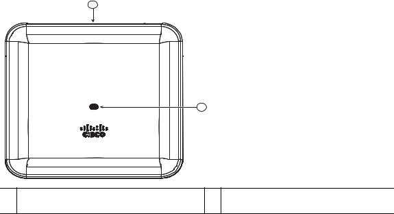
Figure 1 Face of the 2802I Model
2
1 |
|
354571 |
1 Status LED |
2 Location of the ports and connectors on |
|
the head of the AP. |
9
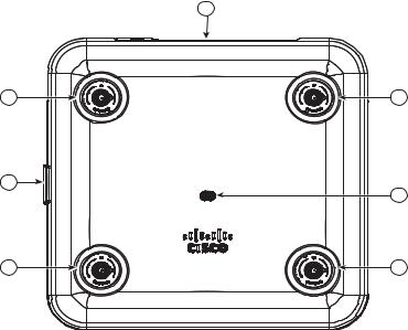
Figure 2 Face of the 2802E Model
6
1 |
7 |
4 |
2 |
5 |
3 |
354569
1 |
Dual-band antenna connector A |
5 |
Status LED |
|
|
|
|
2 |
Dual-band antenna connector B |
6 |
Location of the ports and connectors on the |
|
|
|
head of the AP |
|
|
|
|
3 |
Dual-band antenna connector C |
7 |
Location of the Smart antenna connector |
|
|
port on the right side of the AP |
|
4 |
Dual-band antenna connector D |
|
|
|
|
||
|
|
|
|
The ports and connections on the bottom of the access point are shown in Figure 3.
10

Figure 3 Ports and Connectors on the Head of the 2802E Model
1 |
2 |
3 |
4 |
5 |
6 |
354570 |
1 |
Kensington lock slot |
4 |
USB port |
|
|
|
|
2 |
Mode button |
5 |
Gigabit Ethernet port |
|
|
|
|
3 |
Console port |
6 |
Gigabit Ethernet port |
|
|
|
|
11
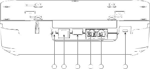
Figure 4 Ports and Connectors on the Head of the 2802I Model
1 |
2 |
3 |
4 |
5 |
6 |
354625
1 |
Mode button |
4 |
Gigabit Ethernet port |
|
|
|
|
2 |
Console port |
5 |
Gigabit Ethernet port |
|
|
|
|
3 |
USB port |
6 |
Kensington lock slot |
|
|
|
|
12
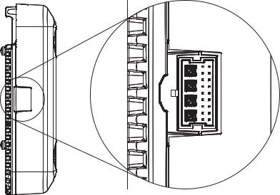
Figure 5 Smart Antenna Connector on the Right Side of the 2802E Model
354568 |
For more information on the Smart antenna connector, see the “What is a Smart Antenna connector?” section on page 30.
13

6 Preparing the AP for Installation
Before you mount and deploy your access point, we recommend that you perform a site survey (or use the site planning tool) to determine the best location to install your access point.
You should have the following information about your wireless network available:
•Access point locations.
•Access point mounting options: below a suspended ceiling, on a flat horizontal surface, or on a desktop.
Note You can mount the access point above a suspended ceiling but you must purchase additional mounting hardware: See “Mounting and Grounding the Access Point” section on page 19 for additional information.
•Access point power options: PoE+ or Cisco Power Injector AIR-PWRINJ6=.
Cisco recommends that you make a site map showing access point locations so that you can record the device MAC addresses from each location and return them to the person who is planning or managing your wireless network.
7 Installation Overview
Installing the access point involves these operations:
Step 1 Performing a Pre-Installation Configuration, page 15 (optional)
Step 2 Mounting and Grounding the Access Point, page 19
Step 3 Powering the Access Point, page 21
Step 4 Preparing the AP for Installation, page 14
14

8 Performing a Pre-Installation Configuration
The following procedures ensure that your access point installation and initial operation go as expected. This procedure is optional.
Note Performing a pre-installation configuration is an optional procedure. If your network controller is properly configured, you can install your access point in its final location and connect it to the network from there. See the “Deploying the Access Point on the Wireless Network” section on page 23 for details.
The following Pre-Installation Configuration procedure given does not include configuring Link Aggregation. For information on configuring Link Aggregation, see the Cisco Wireless LAN Controller Configuration Guide, Release 8.2, at this URL:
http://www.cisco.com/c/en/us/td/docs/wireless/controller/8-2/config-guide/b_cg82.html
The pre-installation configuration setup is illustrated in Figure 6.
15
Loading...