


CTK-501
|
|
|
|
|
|
100 TONES |
|
|
|
|
|
100 SONG BANNK |
|
|||
|
|
|
|
|
100 RHYTHMS |
|
|
|
|
|
|
|
|
|
|
|
|
POWER/MODE |
MAIN VOLUME |
TEMPO |
CHORD BOOK |
|
MUSICAL INFORMATION SYSTEM |
TONE |
|
|
|
|
|
SONG BANK CONTROLLER |
|||
|
|
|
|
|
|
|
|
|
M |
7 |
m |
8 |
7 |
9 |
|
|
|
|
|
|
|
|
|
|
|
|
|
||||||
|
|
|
|
|
|
|
|
FINGERING/PART |
|
|
|
|
|
|
STOP |
|
|
|
|
|
|
|
|
TONE |
|
|
|
|
|
|
|
|
|
|
|
|
|
|
|
TRANSPOSE/ |
RHYTHM |
|
RHYTHM |
M7 |
4 |
dim |
5 |
aug |
6 |
|
100 SONG BANNK KEYBOARD |
|
FINGERED |
|
|
|
TUNE/MIDI |
SONG BANK |
|
|
|||||||
MUSICAL INFORMATION SYSTEM |
|
|
|
|
STATUS |
LEFT/ |
RIGHT/ |
|
|
|
|
|
|
|
||
SONG BANK CONTROLLER |
ON |
CASIO CHORD |
|
|
|
TEMPO |
ACCOMP |
MELODY |
|
|
|
|
|
REW |
FF |
|
NORMAL |
|
|
|
|
:1 OCTAVE UP |
|
|
|
|
|
||||||
|
|
|
|
|
|
MAIN VOLUME |
sus4 |
1 |
-5 |
2 |
add9 |
3 |
|
|||
|
OFF |
|
|
|
|
ACCOMP |
|
:PEDAL(SUSTAIN) |
PLAY/ |
|||||||
|
|
|
|
|
|
VOLUME |
|
|
SONG BANK |
|
|
|
|
|
|
PAUSE |
|
|
|
SYNCHRO/ |
START/ |
|
|
|
|
CLEAR |
0 |
|
|
|
LEFT |
RIGHT |
|
|
|
|
|
FILL-IN |
STOP |
|
|
|
|
|
|
|
|
|
|
ON/OFF |
CTK-501
ELECTRONIC KEYBOARD
CONTENTS
Specifications ................................................................................................................................... |
1 |
Block Diagram .................................................................................................................................. |
2 |
Circuit Description ............................................................................................................................ |
3 |
Adjustment ....................................................................................................................................... |
7 |
Major Waveforms ............................................................................................................................. |
8 |
Printed Circuit Boards ...................................................................................................................... |
9 |
Schematic Diagrams ...................................................................................................................... |
11 |
Exploded View ............................................................................................................................... |
16 |
Parts List ........................................................................................................................................ |
17 |

|
|
|
SPECIFICATIONS |
GENERAL |
|
|
|
Keyboard: |
61 standard-size keys, 5 octaves |
||
Tones: |
100 |
|
|
Polyphony: |
12 notes maximum (6 for certain tones) |
||
Auto accompaniment |
|
|
|
Rhythm patterns: |
100 |
|
|
Tempo: |
Variable (236 steps, = 20 to 255) |
||
Chords: |
2 fingering methods (CASIO CHORD, FINGERED) |
||
Rhythm controller: |
START/STOP, SYNCHRO/FILL-IN |
||
Accomp volume: |
0 to 9 (10 steps) |
||
Song bank |
|
|
|
Tunes: |
100 |
|
|
Controllers: |
PLAY/PAUSE, STOP, REW, FF, LEFT (ON/OFF), RIGHT (ON/OFF) |
||
Musical information |
|
|
|
Name display: |
TONE, RHYTHM, SONG BANK name/number |
||
Tempo: |
Tempo value, metronome, synchro standby, beat indicator |
||
Chord: |
Chord name, Chord form |
||
Fingering: |
Fingering indcators, parts, pedal |
||
Song bank status: |
PLAY, PAUSE, REW, FF |
||
Staff: |
5 octaves with sharp and flat indications |
||
Keyboard: |
5 octaves |
||
MIDI: |
5 multi-timbre receive |
||
Other functions |
|
|
|
Transpose: |
12 steps (–6 semitones to +5 semitones) |
||
Tuning: |
Variable (A4 = approximately 440 Hz ± 50 cents) |
||
Volume: |
0 to 9 (10 steps) |
||
Terminals |
|
|
|
MIDI terminals: |
IN, OUT |
||
Sustain terminal: |
Standard jack |
||
Phones/Output terminal: |
Stereo standard jack |
||
|
Output Impedance: 78 Ω |
||
|
Output Voltage: 4 V (RMS) MAX |
||
Power supply terminal: |
9 V DC |
||
Power supply |
Dual power supply system |
||
Batteries: |
Six D-size batteries |
||
Battery life: |
Approximately 10 hours on manganese batteries |
||
AC adaptor: |
AD-5 |
||
Auto power off: |
Turns power off approximately six minutes after last key operation. Enabled |
||
|
under battery power only, can be disabled manually. |
||
Speaker output: |
2.0 W + 2.0 W |
||
Power consumption: |
9 V |
--- |
7.7 W |
Dimensions (HWD): |
961 × 381 × 139 mm (37-7/8 × 15-1/16 × 5-1/2 inches) |
||
Weight: |
Approximately 5.4 kg (11.91 lbs) (without batteries) |
||
ELECTRICAL
Current drain with 9 V DC: |
120 mA ± 20% |
No sound output |
|
Maximum volume |
750 mA ± 20% |
with 12 keys C1 to B1 pressed in Synth-Lead 1 |
|
Volume: Maximum |
|
Phone output level (Vrms with 8 Ω load each channel): |
78 mV ± 20% |
with key G2 pressed in Synth-Lead 1 |
|
Speaker output level (Vrms with 4 Ω load each channel): |
1250 mV ± 20% |
with key G1 pressed in Synth-Lead 1 |
|
Minimum operating voltage: |
6.0 V |
— 1 —
— 2 —
|
|
|
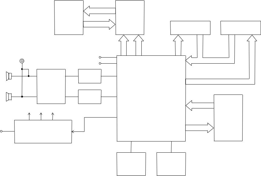
BLOCK DIAGRAM |
|
||
|
|
|
COM1 ~ COM16 |
|
|
|
|
|
|
|
|
LCD Driver |
|
|
|
LCD |
|
SED1278F0A |
|
|
|
|
|
|
|
LSI3 |
|
|
|
|
SEG1 ~ SEG40 |
|
|
|
|
|
|
|
|
RS |
|
|
|
|
DB4 ~ DB7 |
R/W |
KO8 ~ |
|
|
|
|
E |
|||
|
Output |
|
|
|
KO12 |
|
|
|
|
|
|
||
|
|
MIDI IN |
|
|
|
|
|
|
|
|
|
|
|
|
|
|
MIDI OUT |
|
|
|
|
|
|
Filter (L) |
|
|
|
|
|
Power Amp. |
Q206 |
|
|
|
|
|
|
|
|
|
|
|
|
TA8248K |
|
|
|
|
|
|
IC201 |
Filter (R) |
|
CPU |
|
|
|
|
|
MSM 6755B-17 |
||
|
|
|
Q205 |
|
||
|
|
|
|
LSI2 |
|
|
|
|
|
|
|
|
|
|
VC |
VCC DVDD |
APO |
|
|
|
|
|
|
|
|
|
|
DC + 9V IN |
Power |
Supply Circuit |
|
|
|
|
|
|
|
|
|
||
Q201 ~ Q203, Q208, D205
Buttons |
Keyboard |
KI0 ~ KI6
KO0 ~ KO7
MD0 ~ MD7
ROM(2M-bit)
MA0 ~ MA18 LC372100PMG48
LSI1
Reset IC |
Oscillator |
IC1 |
X1, Q1 |
CIRCUIT DESCRIPTION
KEY MATRIX
|
KI0 |
KI1 |
KI2 |
KI3 |
KI4 |
KI5 |
KI6 |
KI7 |
|
|
|
|
|
|
|
|
|
KO0 |
C2 |
G#2 |
E3 |
C4 |
G#4 |
E5 |
C6 |
G#6 |
|
|
|
|
|
|
|
|
|
KO1 |
C#2 |
A2 |
F3 |
C#4 |
A4 |
F5 |
C#6 |
A6 |
|
|
|
|
|
|
|
|
|
KO2 |
D2 |
A#2 |
F#3 |
D4 |
A#4 |
F#5 |
D6 |
A#6 |
|
|
|
|
|
|
|
|
|
KO3 |
D#2 |
B2 |
G3 |
D#4 |
B4 |
G5 |
D#6 |
B6 |
|
|
|
|
|
|
|
|
|
KO4 |
E2 |
C3 |
G#3 |
E4 |
C5 |
G#5 |
E6 |
C7 |
|
|
|
|
|
|
|
|
|
KO5 |
F2 |
C#3 |
A3 |
F4 |
C#5 |
A5 |
F6 |
|
|
|
|
|
|
|
|
|
|
KO6 |
F#2 |
D3 |
A#3 |
F#4 |
D5 |
A#5 |
F#6 |
|
|
|
|
|
|
|
|
|
|
KO7 |
G2 |
D#3 |
B3 |
G4 |
D#5 |
B5 |
G6 |
|
|
|
|
|
|
|
|
|
|
KO8 |
— |
+ |
0 |
Tempo |
Tempo |
Volume |
Volume |
|
Down |
Up |
Down |
Up |
|
||||
|
|
|
|
|
||||
|
|
|
|
|
|
|
|
|
KO9 |
3 |
2 |
1 |
Start/ |
Synchro/ |
Chord |
Accomp |
|
Stop |
Fill-In |
Book |
Volume |
|
||||
|
|
|
|
|
||||
|
|
|
|
|
|
|
|
|
KO10 |
6 |
5 |
4 |
Transpose/ |
Song |
Rhythm |
Tone |
|
Tune/MIDI |
Bank |
|
||||||
|
|
|
|
|
|
|
||
KO11 |
9 |
8 |
7 |
Fingered |
CASIO |
Normal |
Off |
|
Chord |
|
|||||||
|
|
|
|
|
|
|
|
|
KO12 |
FF |
Right |
Play/ |
Stop |
Left |
REW |
|
|
Pause |
|
|
||||||
|
|
|
|
|
|
|
|
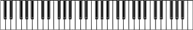
NOMENCLATURE OF KEYS
C#2 D#2 |
F#2 G#2 A#2 |
C#3 D#3 |
F#3 G#3 A#3 |
C#4 D#4 |
F#4 G#4 A#4 |
C#5 D#5 |
F#5 G#5 A#5 |
C#6 D#6 |
F#6 G#6 A#6 |
C2 |
D2 |
E2 |
F2 |
G2 |
A2 |
B2 |
C3 |
D3 |
E3 |
F3 |
G3 |
A3 |
B3 |
C4 |
D4 |
E4 |
F4 |
G4 |
A4 |
B4 |
C5 |
D5 |
E5 |
F5 |
G5 |
A5 |
B5 |
C6 |
D6 |
E6 |
F6 |
G6 |
A6 |
B6 |
C7 |
— 3 —
CPU (LSI2: MSM6755B-17)
The CPU reads sound data from the ROM in accordance with the pressed key and the selected tone; the CPU can read rhythm data simultaneously when a rhythm pattern is selected. Then it provides the left and the right channels’ waveforms separately, by converting the data into the waveforms with two built-in DACs. The CPU also controls key and button input. The following table shows the pin functions of LSI2.
Pin No. |
Terminal |
In/Out |
Function |
1 |
MA14 |
Out |
Address bus |
|
|
|
|
2, 3 |
NCO |
— |
Not used |
|
|
|
|
4 ~ 19 |
MA0 ~ MA13 |
Out |
Address bus |
|
|
|
|
13 |
MRDB |
Out |
Read enable signal |
|
|
|
|
17 |
MCSB |
— |
Not used |
|
|
|
|
20 ~ 27 |
MD0 ~ MD7 |
In/Out |
Data bus |
|
|
|
|
28, 29 |
NC1, NC2 |
— |
Not used |
|
|
|
|
30 |
DGND |
In |
Ground (0 V) source |
|
|
|
|
31 |
DVCC |
In |
+5 V source |
|
|
|
|
32, 33 |
XTLO, XTLI |
In/Out |
20 MHz clock input/output |
|
|
|
|
34 |
NC3 |
— |
Not used |
|
|
|
|
35 |
RSTB |
In |
Reset signal input |
|
|
|
|
36 |
P24/RXD |
In |
MIDI signal input |
|
|
|
|
37 |
P25/TXD |
Out |
MIDI signal output |
|
|
|
|
38 |
NMI |
In |
Power ON signal input. Connected to +5 V. |
|
|
|
|
39 |
APO |
Out |
APO (Auto Power Off) signal output |
|
|
|
|
40 |
NC4 |
— |
Not used |
|
|
|
|
41 |
REFH |
Out |
Terminal for the internal DAC |
|
|
|
|
42, 43 |
NC5, NC6 |
— |
Not used |
|
|
|
|
44 |
DAOR |
Out |
Right channel sound waveform output |
|
|
|
|
45 |
NC7 |
— |
Not used |
|
|
|
|
46 |
AVdac |
In |
+5 V source for the internal DAC |
|
|
|
|
47 |
DAOL |
Out |
Left channel sound waveform output |
|
|
|
|
48 |
REFL |
Out |
Terminal for the internal DAC and ADC |
|
|
|
|
49 |
AGdac |
In |
Ground source for internal DAC |
|
|
|
|
50 |
AGadc |
In |
Ground source for internal ADC |
|
|
|
|
51 |
ANI |
In |
APO cancellation signal |
|
|
|
|
52 |
AVadc |
In |
+5 V source for the internal ADC |
|
|
|
|
53 |
NC8 |
— |
Not used |
|
|
|
|
54 |
MOD0 |
In |
Mode selection terminal. Connected to +5 V. |
|
|
|
|
55, 56 |
MOD1, MOD2 |
In |
Mode selection terminal. Connected to ground. |
|
|
|
|
57 |
P40 |
In |
Pedal signal input |
|
|
|
|
58 ~ 64 |
KI0/P30 ~ KI7/P36 |
In |
Terminals for key/button input signal |
|
|
|
|
65 |
KI7/P37 |
— |
Not used |
|
|
|
|
66 ~ 73 |
KO0/P50 ~ KO7/P57 |
Out |
Terminals for key scan signal |
|
|
|
|
— 4 —
Pin No. |
Terminal |
In/Out |
Function |
74 ~ 77 |
DB4 ~ DB7 |
Out |
Data bus for the LCD driver |
|
|
|
|
78 |
NC9 |
— |
Not used |
|
|
|
|
79 |
LVCC |
In |
+5 V source |
|
|
|
|
80 ~ 84 |
KO8 ~ KO12 |
Out |
Terminals for button scan signal |
|
|
|
|
85 ~ 87 |
P65 ~ P67 |
— |
Not used |
|
|
|
|
88 |
RS |
Out |
Control signal for the LCD driver |
|
|
|
|
89 |
R/W |
Out |
Read/Write signal for the LCD driver |
|
|
|
|
90 |
E |
Out |
Chip enable signal for the LCD driver |
|
|
|
|
91 ~ 95 |
P73 ~ P77 |
— |
Not used |
|
|
|
|
96 |
LGND |
In |
Ground source |
|
|
|
|
97, 100 |
MA18, MA15 |
Out |
Address bus |
|
|
|
|
LCD DRIVER (LSI3: SED1278F0A)
The LCD driver can drive a dot matrix LCD having 40 segment and 16 common lines. The LSI contains 240 graphic symbols in the built-in character generator ROM, and stores 80 characters in the built-in display data RAM. In accordance with command from the CPU, the LSI is capable of displaying up to 16 characters simultaneously. The following table shows the pin functions of LSI3.
Pin No. |
Terminal |
In/Out |
Function |
|
1 ~ 22, |
SEG1 ~ SEG40 |
Out |
Segment signal output |
|
63 ~ 80 |
||||
|
|
|
||
|
|
|
|
|
23 |
VSS |
— |
GND (0 V) source |
|
|
|
|
|
|
24, 25 |
OSC1, OSC2 |
In/Out |
Terminals for the built-in clock pulse generator. The external |
|
resistor connected determines the oscillation frequency. |
||||
|
|
|
||
|
|
|
LCD drive voltage input. |
|
26 ~ 30 |
V1 ~ V5 |
In |
Those voltages are used for generating the stepped pulse of |
|
|
|
|
the LCD drive signals. |
|
|
|
|
|
|
31, 32 |
LP, XCLS |
— |
Not used |
|
|
|
|
|
|
33 |
VDD |
In |
DVDD (+5 V) source |
|
|
|
|
|
|
34, 35 |
FR, DO |
— |
Not used |
|
|
|
|
|
|
36 |
RS |
In |
Data/command determination terminal. |
|
High: data, Low: command |
||||
|
|
|
||
|
|
|
|
|
37 |
R/W |
In |
Read/Write terminal. High: read, Low: write |
|
|
|
|
|
|
|
|
|
Chip enable signal. |
|
38 |
E |
In |
High: enable, the writing is done at fall edge. |
|
|
|
|
Low: disenable |
|
|
|
|
|
|
39 ~ 42 |
DB0 ~ DB3 |
— |
Not used. Connected to GND (0 V) |
|
|
|
|
|
|
43 ~ 46 |
DB4 ~ DB7 |
In/Out |
Data bus |
|
|
|
|
|
|
47 ~ 62 |
COM1 ~ COM16 |
Out |
Common signal/output |
|
|
|
|
|
— 5 —
 Loading...