


69RG15
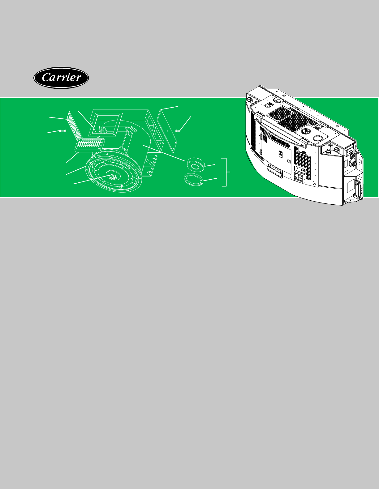
Diesel Generator Set
T--272 Rev J
SERVICE PARTS LIST
for
69RG15
Diesel Generator Set
Prior to PID RG1135
1
2
3
4
5, 6
7
8
9
10, 11, 12
14
13

SERVICE PARTS LIST
DIESEL DRIVEN GENERATOR SET
MODEL
69RG15

i
T--272PL
TABLE OF CONTENTS
PARAGRAPH NUMBER Page
INTRODUCTION iv...........................................................................
MODEL AND PRODUCT IDENTIFICATION (PID) NUMBERS iv....................................
ORDERING INSTRUCTIONS iv................................................................
GENERAL NOTES iv.........................................................................
PAINTED PARTS COLOR SYSTEM v..........................................................
MODEL CHART vi............................................................................
1 QUICK LIST 1.........................................................................
1.a Quick List - Butt Connectors, Clamps, Electrical Cables, Filters, Grease, Paint, Spiral Rap,
Ty-raps And Wire Terminals 1...............................................................
2 UNIT MOUNTING 2....................................................................
2.a Unit Mounting - Common Parts 3......................................................
2.a.1 Unit Mounting - Pin Mount 3..........................................................
2.a.2 Unit Mounting - Clamp Mount 3.......................................................
2.a.3 Unit Mounting - Pin Mount With Clamp Provision 3......................................
2.b Unit Mounting - Common Parts 5......................................................
2.b.1 Unit Mounting - Pin Mount 5..........................................................
2.b.2 Unit Mounting - Clamp Mount 5.......................................................
2.b.3 Unit Mounting - Pin Mount With Clamp Provision 5......................................
2.c Unit Mounting - Pin Mount 7..........................................................
3 UNIDRIVE 8...........................................................................
3.a Unidrive Assembly - With And Without Throttle Guard 8..................................
3.a.1 Unidrive - With Throttle Guard 9......................................................
3.b Unidrive Assembly - Shockmount, Disc Drive And Pulley 10...............................
3.c Generator -- Main Alternator 12........................................................
4 FUEL SYSTEM 14.......................................................................
4.a Fuel System 14......................................................................
4.b Fuel System - Common Parts 17.......................................................
4.b.1 Fuel System - With Aluminum Cap 17..................................................
4.b.2 Fuel System - With Brass Cap 17......................................................
5 OIL SYSTEM 18........................................................................
5.a Oil System (Horizontal or Vertical - Vertical Shown) 19....................................
6 BATTERY 20...........................................................................
6.a Battery - Post Type 21................................................................
7 COOLANT SYSTEM 22..................................................................
7.a Coolant System - Common Parts 22....................................................
7.b Coolant System - Specific Parts 24.....................................................
7.b.1 Coolant System - Prior To RG0337 25..................................................
7.b.2 Coolant System -RG0338 Thru RG0679 25..............................................
7.b.3 Coolant System - Starting With RG0691 25..............................................
8 OIL BATH AIR FILTER 26................................................................
9 EXHAUST SYSTEM 27..................................................................
9.a Aluminized Steel With And Without Guard - Common Parts 27.............................
9.a.1 Exhaust System With Guard 27.........................................................

ii
T--272PL
PARAGRAPH NUMBER
Page
10 BATTERY CHARGER 28.................................................................
10.a Battery Charger - Solid State 28.......................................................
10.a Battery Charger - Solid State - Common Parts 29........................................
10.a.1 Battery Charger - Solid State - Harness 29..............................................
10.a.2 Battery Charger - Solid State - Harness 29..............................................
10.a.3 Battery Charger - Solid State - Harness 29..............................................
10.a.4 Battery Charger - Solid State - Harness 29..............................................
10.a.5 Battery Charger - Solid State - Harness 29..............................................
10.b Battery Charger - Alternator 30........................................................
11 SKINS OPTION 32......................................................................
1 1.a Skins Option - Latched Door With Access Panels And Bumpers 32.........................
1 1.b Skins Option - Common Parts 35......................................................
1 1.b.1 Skins Option - Cover - Bolted Door with Back Grille 35....................................
1 1.b.2 Skins Option - Cover - Bolted Door with Notched Back Grille 35............................
12 LABELS 36.............................................................................
12.a Labels-English/Spanish, 102and130Gallon, Pin & Clamp Mount,CE&Auto-Restart-CommonParts
37.................................................................................
12.a.1 Labels - English/Spanish, 102 and 130 Gallon, Pin Mount 37...............................
12.a.2 Labels - English/Spanish, 102 and 130 Gallon, Clamp Mount 37............................
12.a.3 Labels - English/Spanish, 102 and 130 Gallon, Pin And Clamp Mount, No Auto-Restart 37.....
12.a.4 Labels - English/Spanish, 102 and 130 Gallon, CE, No Auto-Restart 37.....................
12.a.5 Labels - English/Spanish, 102 and 130 Gallon, CE, Auto-Restart 37........................
13 CONTROL BOX 38......................................................................
13.a Control Box - 91-00289-00, -01 and -02 - Common Parts - Includes: 39.....................
13.a.1 Control Box - 91-00289-00 - Includes: 39................................................
13.a.2 Control Box - 91-00289-01 - Includes: 39................................................
13.a.3 Control Box - 91-00289-02 - Includes: 39................................................
13.b Control Box - 91-00300-00, -01, -02 And 91-00338-00,--03 - Common Parts 40...............
13.c Control Box - 91-00300-00, -01, -02 And 91-00338-00,-- 03 - Specific Parts 42...............
13.c.1 Control Box - 91-00300-00 - Includes: 42................................................
13.c.2 Control Box - 91-00300-01 - Includes: 43................................................
13.c.3 Control Box - 91-00300-02 - Includes: 43................................................
13.c.4 Control Box - 91-00338-00 - Includes: 43................................................
13.c.5 Control Box - 91-00338-03 - Includes: 43................................................
13.d Control Box - Auto-Restart - 91-00300-03, -05 And 91--00338--02.--04,--08 - Common Parts 44.
13.e Control Box - Auto Restart - 91-00300-03, -05 And 91--00338--02, --04,--08 - Specific Parts 46..
13.e.1 Control Box - Auto Restart - 91-00300-03 - Includes: 46...................................
13.e.2 Control Box - Auto Restart - 91-00300-05 - Includes: 47...................................
13.e.3 Control Box - Auto Restart - 91-00338-02 - Includes: 47...................................
13.e.4 Control Box - Auto Restart - 91-00338-04, --08 - Includes: 47..............................

iii
T--272PL
PARAGRAPH NUMBER
Page
14 VOLTAGE 48...........................................................................
14.a.1 Voltage 49..........................................................................
14.a.2 Voltage -- 460V A.R. W/Alt 49..........................................................
14.b Voltage -- Receptacle Box -- 460V 51...................................................
14.c Voltage - Receptacle Box -- 230 & 460 Volt & Auto-Restart With Alternator - Common Parts 52.
14.d Voltage - Receptacle Box -- 230 & 460 Volt & Auto-Restart With Alternator - Specific Parts 54..
14.d.1 Voltage - Specific Parts for 91-00301-00 - 460 Volt - Includes: 54...........................
14.d.2 Voltage - Receptacle Box -- Specific Parts for 91-00301-01 - 460 Volt - Includes: 55...........
14.d.3 Voltage - Receptacle Box -- Specific Parts for 91-00301-02 - 460 Volt - Includes: 55...........
14.d.4 Voltage - Receptacle Box -- Specific Parts for 91-00301-03 - 230 Volt - Includes: 55...........
14.d.5 Voltage - Receptacle Box -- Specific Parts for 91-00301-04 - A/R With Alt. - Includes: 55......
14.e Voltage Receptacle Box - 460 Volt - 91--00340--00 56....................................
14.e Voltage Receptacle Box - 460 Volt - 91--00340--00- Continued 57..........................
15 VOLTMETER 58........................................................................
15.a Voltmeter - No Voltmeter And Greenband - Common Parts 58...............................
15.a.1 Voltmeter - No Voltmeter, Blank-off Plate 58.............................................
15.a.2 Voltmeter - Voltmeter - Greenband 58...................................................
iv
T272PL
INTRODUCTION
This parts list identifies service replacement parts for the Carrier Transicold Diesel-Driven Generator Set
listed in the model chart below. This parts list does not include detailed replacement parts for the engine listed
in the first chart below. Detailed parts identification for these items may be found in the applicable parts list.
The form numbers for the engine omit revision dash numbers. For example, the latest engine list may have an
-01 added to the basic number to read 62-03459-01. Therefore, when forms are ordered the latest revision will
be sent.
MANUAL/
FORM NO.
ENGINE
PART NO.
EQUIPMENT
COVERED
TYPE OF
MANUAL/FORM
62-03741 26-00105-00 CT4-134-DI Workshop
62-03459 26-00105-00 CT4-134-DI Engine Parts List
62-10301 26-00115-01* CT4-134-DI* Workshop
62-10295 26-00115-01* CT4-134-DI* Engine Parts List
* Starting With RG0459 and Serial Number XA00001
MODEL AND PRODUCT IDENTIFICATION (PID) NUMBERS
Beginning with early 1995 production, in addition to a model number, Carrier Transicold began using a parts
identification (PID) number in the format of RG0000. In this manual, the PID number is shown in boldface to
point out variations within models. Please include the PID number, in addition to the model number, when
ordering and inquiring about your unit.
ORDERING INSTRUCTIONS
All orders and inquiries for parts must include:
SPart Identification Number (PID)
SUnit Serial Number
SPart Number
SDescription of Part
SQuantity Required
Address all correspondence for parts to the following address:
CARRIER TRANSICOLD DIVISION
Replacement Components Group
TR-20, P.O. Box 4805
Syracuse, New Y ork 13221
or
Fax to: (315) 432-3778
GENERAL NOTES
To find replacement parts, consult table of contents, and turn to the appropriate page for the illustrated
breakdown of replacement parts. The following letter designations are used to classify parts throughout this
list:
A/R As Required.
PID Parts Identification Number -- essential to identify unit configuration.
PL Purchase locally.
SST Stainless Steel -- 300 Series unless otherwise specified.
SV Suffix SV -- added to the part number designates service part replacement part.

v T-272PL
PAINTED PARTS COLOR SYSTEM
Available paint colors: (Other than White Cloud or Hull Blue)
P AINT COLOR
PART NO.
Sky Blue 36-00048-28
Flame Orange 36-00048-27
Citrus Orange 36-00048-29
Raven Black 36-00048-04
Red 36-00048-57
Overview of the new numbering system:
A typicalpart number appears as: 79--01741--00 (access door). To order an access door insky blueyou add
the last three digits of the specialcolor paintand then add thespecific dash number forthe colorof thatpaint.
For example:
Sky blue paint P/N is 36--00048--28.
The last three digits of the blue paint are: 048
The specific dash number is: 28
The painted parts system looks like this:
79-01741-00 Standard P/N for the access door.
048 Last 3 digits of special color paint.
28 Specific dash # for color of paint.
79-01741-0004828 P/N For Special Painted Door
Data Entry Note:
The above is how you should see most parts being ordered. Certain customers may have a character
constraintthat willonlyallowthemtoinput14charactersintheirsystemandournew painted part numbersare
16 characters long. Therefore, they will be ordering these parts without the dashes and will look like the
following, 79017410004828.
vi
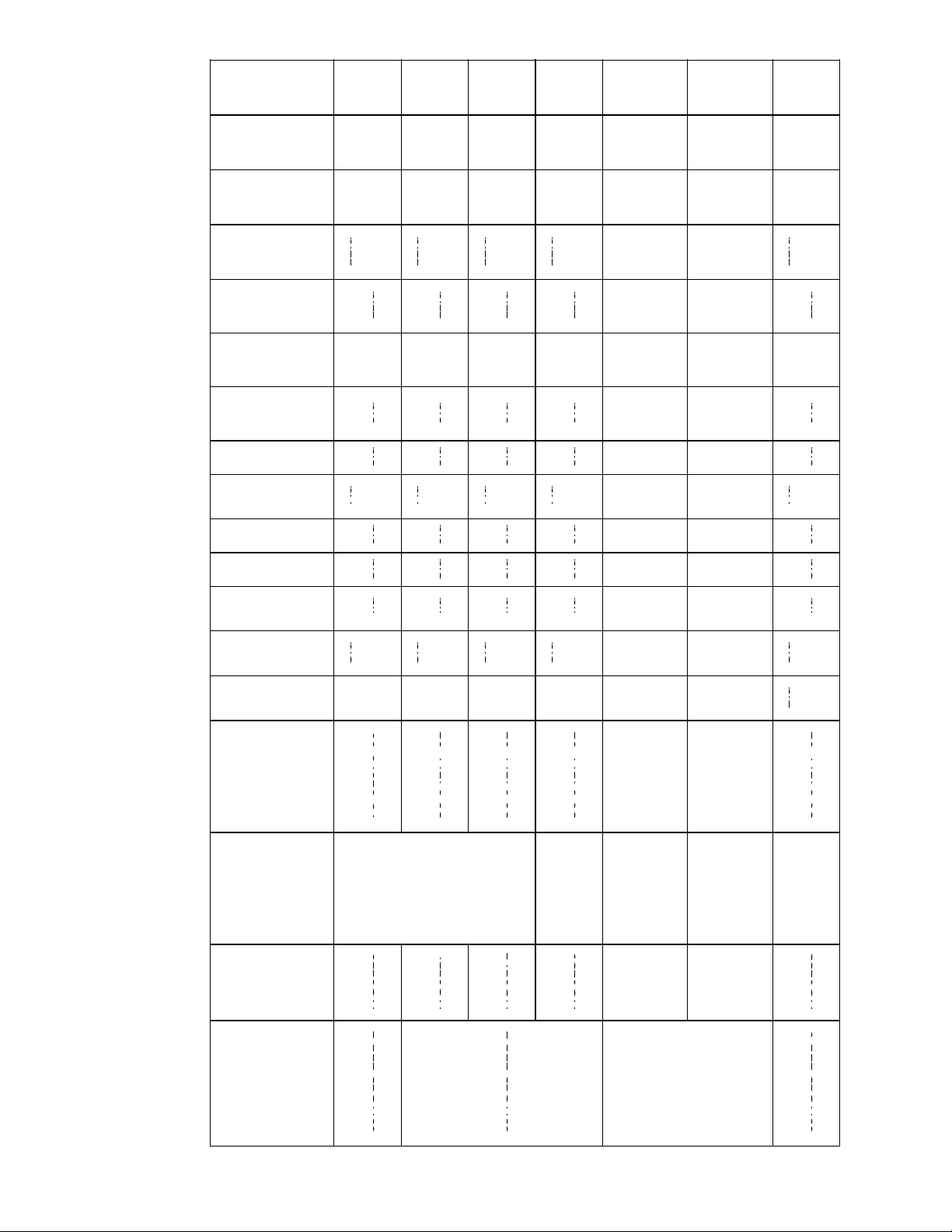
MODEL CHART
NOTE
The numbers shown in the model chart below refer to the section numbers that cover that option.
Please refer to the table of contents for page numbers.
Model Number
PID Number
Schematic/
Wiring
Diagram
Decals
Fuel Tank
Assembly
Service
Part
Number
Unit Mounting
Unidrive
Fuel System
Oil System
Battery
Coolant System
Air Filter
Exhaust System
Battery Charger
Skins Option
Labels
Control Box
Voltage
Voltmeter
2
a
3.a 7.a
1
0
a
12.a
1
3
a
1
4
a
1
1
5
a
69RG15-221-1 RG0116 79-01670-00
2.a
2
a
1
3
.
a
3.b
4.a 5.a 6.a
7
.
a
7.b
8.a 9.a
10.a
1
0
a
1
11.a
1
2
.
a
12.a.1
13.a
1
3
a
1
14.a.1
1
4
b
15.a
1
5
a
2
6
9
R
G
1
5
2
2
1
1
R
G
0
1
1
6
7
9
0
1
6
7
0
0
0
2.a.1
3.c
4
.
a
5
.
a
6
.
a
7.b.1
8
.
a
9
.
a
10.a.1
1
1
.
a
12.a.3
13.a.1 14.b 15.a.2
6
2
0
2
8
3
9
0
0
/
2
a
3.a 7.a
1
0
a
12.a
1
3
a
1
4
a
1
1
5
a
RG0117
62-02839-00/
6
2
-
0
2
8
4
0
-
0
0
86-04177-01
2.a
2
a
1
3
.
a
3.b
4.a 5.a 6.a
7
.
a
7.b
8.a 9.a
10.a
1
0
a
1
11.a
1
2
.
a
12.a.1
13.a
1
3
a
1
14.a.1
1
4
b
15.a
1
5
a
2
R
G
0
1
1
7
6
2
-
0
2
8
4
0
-
0
0
8
6
0
4
1
7
7
0
1
2.a.1
3.c
4
.
a
5
.
a
6
.
a
7.b.1
8
.
a
9
.
a
10.a.1
1
1
.
a
12.a.3
13.a.1 14.b 15.a.2
2
a
3.a 7.a
1
0
a
12.a
1
3
a
1
4
a
1
1
5
a
69RG15-221-2 RG0171 86-04177-01
2.a
2
a
1
3
.
a
3.b
4.a 5.a 6.a
7
.
a
7.b
8.a 9.a
10.a
1
0
a
1
11.a
1
2
.
a
12.a.1
13.a
1
3
a
1
14.a.1
1
4
b
15.a
1
5
a
2
6
9
R
G
1
5
2
2
1
2
R
G
0
1
7
1
8
6
0
4
1
7
7
0
1
2.a.1
3.c
4
.
a
5
.
a
6
.
a
7.b.1
8
.
a
9
.
a
10.a.1
1
1
.
a
12.a.3
13.a.1 14.b 15.a.2
6
2
1
0
0
2
3
0
0
/
2
a
3.a 7.a
1
0
a
12.a
1
3
a
1
4
a
1
1
5
a
RG0230
62-10023-00/
6
2
-
0
2
8
4
0
-
0
0
86-04177-01
2.a
2
a
1
3
.
a
3.b
4.a 5.a 6.a
7
.
a
7.b
8.a 9.a
10.a
1
0
a
1
11.a
1
2
.
a
12.a.1
13.a
1
3
a
2
14.a.1
1
4
b
15.a
1
5
a
2
R
G
0
2
3
0
6
2
-
0
2
8
4
0
-
0
0
8
6
0
4
1
7
7
0
1
2.a.1
3.c
4
.
a
5
.
a
6
.
a
7.b.1
8
.
a
9
.
a
10.a.1
1
1
.
a
12.a.3
13.a.2 14.b 15.a.2
2
3.a
3
1
7.a
9
1
0
1
1
b
12.a 13.b
14.a.1
1
4
1
RG0205
62-02991-00/
6
2
-
0
2
8
4
0
-
0
0
86-04177-02
2.a
2
a
1
3.a.1
3
b
4.a 5.a 6.a
7
.
a
7.b
8.a
9.a
9
a
1
10.a
1
0
a
2
11.b
1
1
b
1
1
2
.
a
12.a.1
1
3
.
b
13.c
14.c
1
4
d
15.a
1
5
a
2
6
9
R
G
1
5
2
2
1
3
6
2
-
0
2
8
4
0
-
0
0
2
.a.
1
3
.
b
3.c
7.b.1
9
.a.
1
1
0
.a.
2
1
1
.
b
.
1
12.a.4 13.c.1
1
4
.
d
14.d.1
1
5
.a.
2
69
R
G
15-221-3
2
3.a
3
1
7.a
9
1
0
1
1
b
12.a 13.b
14.a.1
1
4
1
RG0257
62-10041-01/
6
2
-
0
2
8
4
0
-
0
0
86-04177-03
2.a
2
a
1
3.a.1
3
b
4.a 5.a 6.a
7
.
a
7.b
8.a
9.a
9
a
1
10.a
1
0
a
4
11.b
1
1
b
1
1
2
.
a
12.a.1
1
3
.
b
13.c
14.c
1
4
d
15.a
1
5
a
2
6
2
-
0
2
8
4
0
-
0
0
2
.a.
1
3
.
b
3.c
7.b.1
9
.a.
1
1
0
.a.
4
1
1
.
b
.
1
12.a.4 13.c.1
1
4
.
d
14.d.2
1
5
.a.
2
6
2
1
0
0
1
0
0
/
2.a 3.a 7.a
1
0
a
12.a
1
3
a
1
4
a
1
1
5
a
69RG15-221-6 RG0233
62-10041-00/
6
2
-
0
2
8
4
0
-
0
0
86-04177-01
2
.
a
2.a.1
3
.
a
3.b
4.a 5.a 6.a
7
.
a
7.b
8.a 9.a
10.a
1
0
a
1
11.a
1
2
.
a
12.a.1
13.a
1
3
a
3
14.a.1
1
4
b
15.a
1
5
a
1
6
9
R
G
1
5
2
2
1
6
R
G
0
2
3
3
6
2
-
0
2
8
4
0
-
0
0
8
6
0
4
1
7
7
0
1
2.a.3 3.c
4
.
a
5
.
a
6
.
a
7.b.1
8
.
a
9
.
a
10.a.1
1
1
.
a
12.a.3
13.a.3 14.b 15.a.1

vii
Model Number
Voltmeter
Voltage
Control Box
Labels
Skins Option
Battery Charger
Exhaust System
Air Filter
Coolant System
Battery
Oil System
Fuel System
Unidrive
Unit Mounting
Fuel Tank
Assembly
Service
Part
Number
Schematic/
Wiring
Diagram
Decals
PID Number
6
2
0
2
8
3
9
0
0
/
2
a
3.a 7.a
1
0
a
12.a
1
3
a
1
4
a
1
1
5
a
RG0145
62-02839-00/
6
2
-
0
2
8
4
0
-
0
0
86-04177-01
2.a
2
a
2
3
.
a
3.b
4.a 5.a 6.a
7
.
a
7.b
8.a 9.a
10.a
1
0
a
1
11.a
1
2
.
a
12.a.2
13.a
1
3
a
1
14.a.1
1
4
b
15.a
1
5
a
2
6
9
R
G
1
5
3
2
1
2
R
G
0
1
4
5
6
2
-
0
2
8
4
0
-
0
0
8
6
0
4
1
7
7
0
1
2.a.2
3.c
4
.
a
5
.
a
6
.
a
7.b.1
8
.
a
9
.
a
10.a.1
1
1
.
a
12.a.3
13.a.1 14.b 15.a.2
69
R
G
15-321-2
6
2
1
0
0
2
3
0
0
/
2
a
3.a 7.a
1
0
a
12.a
1
3
a
1
4
a
1
1
5
a
RG0232
62-10023-00/
6
2
-
0
2
8
4
0
-
0
0
86-04177-01
2.a
2
a
2
3
.
a
3.b
4.a 5.a 6.a
7
.
a
7.b
8.a 9.a
10.a
1
0
a
1
11.a
1
2
.
a
12.a.2
13.a
1
3
a
2
14.a.1
1
4
b
15.a
1
5
a
2
R
G
0
2
3
2
6
2
-
0
2
8
4
0
-
0
0
8
6
0
4
1
7
7
0
1
2.a.2
3.c
4
.
a
5
.
a
6
.
a
7.b.1
8
.
a
9
.
a
10.a.1
1
1
.
a
12.a.3
13.a.2 14.b 15.a.2
6
2
0
2
8
3
9
0
0
/
2
a
3.a 7.a
1
0
a
12.a
1
3
a
1
4
a
1
1
5
a
69RG15-421-2 RG0170
62-02839-00/
6
2
-
0
2
8
4
0
-
0
0
86-04210-00
2.a
2
a
1
3
.
a
3.b
4.a 5.a 6.a
7
.
a
7.b
8.a 9.a
10.a
1
0
a
1
11.a
1
2
.
a
12.a.1
13.a
1
3
a
1
14.a.1
1
4
b
15.a
1
5
a
2
6
9
R
G
1
5
4
2
1
2
R
G
0
1
7
0
6
2
-
0
2
8
4
0
-
0
0
8
6
0
4
2
1
0
0
0
2.a.1
3.c
4
.
a
5
.
a
6
.
a
7.b.1
8
.
a
9
.
a
10.a.1
1
1
.
a
12.a.3
13.a.1 14.b 15.a.2
6
2
1
0
0
2
3
0
0
/
2
a
3.a 7.a
1
0
a
12.a
1
3
a
1
4
a
1
1
5
a
69RG15-421-3 RG0231
62-10023-00/
6
2
-
0
2
8
4
0
-
0
0
86-04210-00
2.a
2
a
1
3
.
a
3.b
4.a 5.a 6.a
7
.
a
7.b
8.a 9.a
10.a
1
0
a
1
11.a
1
2
.
a
12.a.1
13.a
1
3
a
2
14.a.1
1
4
b
15.a
1
5
a
2
6
9
R
G
1
5
4
2
1
3
R
G
0
2
3
1
6
2
-
0
2
8
4
0
-
0
0
8
6
0
4
2
1
0
0
0
2.a.1
3.c
4
.
a
5
.
a
6
.
a
7.b.1
8
.
a
9
.
a
10.a.1
1
1
.
a
12.a.3
13.a.2 14.b 15.a.2
6
2
0
2
8
3
9
0
0
/
2
a
3.a 7.a
1
0
a
12.a
1
3
a
1
4
a
1
1
5
a
69RG15-521-3 RG0181
62-02839-00/
6
2
-
0
2
8
4
0
-
0
0
86-04210-00
2.a
2
a
2
3
.
a
3.b
4.a 5.a 6.a
7
.
a
7.b
8.a 9.a
10.a
1
0
a
1
11.a
1
2
.
a
12.a.2
13.a
1
3
a
1
14.a.1
1
4
b
15.a
1
5
a
2
6
9
R
G
1
5
5
2
1
3
R
G
0
1
8
1
6
2
-
0
2
8
4
0
-
0
0
8
6
0
4
2
1
0
0
0
2.a.2
3.c
4
.
a
5
.
a
6
.
a
7.b.1
8
.
a
9
.
a
10.a.1
1
1
.
a
12.a.3
13.a.1 14.b 15.a.2
Beginning in early 1998 Carrier Transicold began implementing a new model numbering system starting with PID RG0337.
Model Number
PID Number
Schematic/
Wiring
Diagram
Decals
Fuel Tank
Assembly
Service
Part
Number
Unit Mounting
Unidrive
Fuel System
Oil System
Battery
Coolant System
Air Filter
Exhaust System
Battery Charger
Skins Option
Labels
Control Box
Voltage
Voltmeter
2
b
3.a 7.a
1
0
12.a 13.b
14.a.1
1
4
1
69RG15-102P-01 RG0364
62-10041-01
6
2
-
0
2
8
4
0
-
0
0
86-04301-04
2.b
2
b
1
3
.
a
3.b
4.a 5.a 6.a
7
.
a
7.b
8.a 9.a
10.a
1
0
a
4
11.a
1
2
.
a
12.a.1
1
3
.
b
13.c
14.c
1
4
d
15.a
1
5
a
1
6
2
-
0
2
8
4
0
-
0
0
2
.
b
.
1
3.c 7.b.2
1
0
.a.
4
12.a.3 13.c.2
1
4
.
d
14.d.3
1
5
.a.
1

viii
Model Number
Voltmeter
Voltage
Control Box
Labels
Skins Option
Battery Charger
Exhaust System
Air Filter
Coolant System
Battery
Oil System
Fuel System
Unidrive
Unit Mounting
Fuel Tank
Assembly
Service
Part
Number
Schematic/
Wiring
Diagram
Decals
PID Number
2
b
3.a
3
1
7.a
9
1
0
1
1
b
12.a 13.d
14.a.1
1
4
1
RG0466 62-10386-00 86-04301-09
2.b
2
b
1
3.a.1
3
b
4.a 5.a 6.a
7
.
a
7.b
8.a
9.a
9
a
1
10.a
1
0
a
3
11.b
1
1
b
1
1
2
.
a
12.a.1
1
3
.
d
13.e
14.c
1
4
d
15.a
1
5
a
1
2
.
b
.
1
3
.
b
3.c
7.b.2
9
.a.
1
1
0
.a.
3
1
1
.
b
.
1
12.a.5 13.e.1
1
4
.
d
14.d.3
1
5
.a.
1
2
b
3.a
3
1
7.a
9
1
1
b
12.a 13.d
14.a.1
1
4
1
RG0596 62--10547--00 86-04301-09
2.b
2
b
1
3.a.1
3
b
4.a 5.a 6.a
7
.
a
7.b
8.a
9.a
9
a
1
10.b
11.b
1
1
b
1
1
2
.
a
12.a.1
1
3
.
d
13.e
14.c
1
4
d
15.a
1
5
a
1
6
9
R
G
1
5
1
0
2
P
0
2
2
.
b
.
1
3
.
b
3.c
7.b.2
9
.a.
1
1
1
.
b
.
1
12.a.5 13.e.2
1
4
.
d
14.d.5
1
5
.a.
1
69
R
G
15-102
P
-02
2
b
3.a
b
9
1
1
b
12.a 13.d
14.a.2
1
4
1
RG0654 62--10547--00 86-04301-09
2.b
2
b
1
3
.
a
3.b
4.b
4
b
1
5.a 6.a
7.a
7
b
3
8.a
9.a
9
a
1
10.b
11.b
1
1
b
2
1
2
.
a
12.a.1
1
3
.
d
13.e
14.c
1
4
d
15.a
1
5
a
1
2
.
b
.
1
3.c
4
.
b
.
1
7
.
b
.
3
9
.a.
1
1
1
.
b
.
2
12.a.5 13.e.2
1
4
.
d
14.d.5
1
5
.a.
1
2
b
3.a
b
9
1
1
b
12.a 13.d
14.a.2
1
4
1
RG0697 62--10710--00 86-04301-09
2.b
2
b
1
3
.
a
3.b
4.b
4
b
1
5.a 6.a
7.a
7
b
3
8.a
9.a
9
a
1
10.a
11.b
1
1
b
2
1
2
.
a
12.a.1
1
3
.
d
13.e
14.c
1
4
d
15.a
1
5
a
1
2
.
b
.
1
3.c
4
.
b
.
1
7
.
b
.
3
9
.a.
1
1
1
.
b
.
2
12.a.5 13.e.3
1
4
.
d
14.d.5
1
5
.a.
1
6
9
R
G
1
5
1
0
2
P
0
3
RG0736 62--10593--00 86-04301-09
2.b
2.b.1
3.a
3.b
3.c
4.b
4.b.1
5.a 6.a
7.a
7.b
7.b.3
8.a
9.a
9.a.1
10.a
10.a.5
11.b
11.b.1
12.a
12.a.1
12.a.4
13.b
13.c
13.c.4
14.a.1
14.c
14.d
14.d.3
15.a
15.a.1
69
R
G
15-102
P
-03
RG0924 62--10937--00 86-04301-09
2.b
2.b.1
3.a
3.b
3.c
4.b
4.b.1
5.a 6.a
7.a
7.b
7.b.3
8.a
9.a
9.a.1
10.a
10.a.5
11.b
11.b.1
12.a
12.a.1
12.a.4
13.d
13.e
13.e.4
14.a.1
14.c
14.d
14.d.3
15.a
15.a.1
69RG15-102P-04 RG0836 62--10937--00 86-04301-09
2.b
2.b.1
3.a
3.b
3.c
4.b
4.b.1
5.a 6.a
7.a
7.b
7.b.3
8.a
9.a
9.a.1
10.b
11.b
11.b.1
12.a
12.a.1
12.a.4
13.b
13.c
13.c.5
14.a.1
14.e
15.a
15.a.1

ix
Model Number
Voltmeter
Voltage
Control Box
Labels
Skins Option
Battery Charger
Exhaust System
Air Filter
Coolant System
Battery
Oil System
Fuel System
Unidrive
Unit Mounting
Fuel Tank
Assembly
Service
Part
Number
Schematic/
Wiring
Diagram
Decals
PID Number
2
b
3.a 7.a
1
0
12.a 13.b
14.a.1
1
4
1
RG0423
62-10041-02
6
2
-
0
2
8
4
0
-
0
0
86-04301-05
2.b
2
b
3
3
.
a
3.b
4.a 5.a 6.a
7
.
a
7.b
8.a 9.a
10.a
1
0
a
4
11.a
1
2
.
a
12.a.1
1
3
.
b
13.c
14.c
1
4
d
15.a
1
5
a
1
6
9
R
G
1
5
1
0
2
W
0
1
6
2
-
0
2
8
4
0
-
0
0
2
.
b
.
3
3.c 7.b.2
1
0
.a.
4
12.a.3 13.c.2
1
4
.
d
14.d.3
1
5
.a.
1
69RG15-102W-01
R
G
0
4
7
1
6
2
1
0
3
4
7
0
0
8
6
0
4
3
0
1
0
4
2.b
2
b
1
3.a
3
b
4
a
5
a
6
a
7.a
7
b
8
a
9
a
10.a
1
1
a
12.a
1
2
a
1
13.b
1
3
c
14.a.1
14.c
15.a
R
G
0471 62-10347-00 86-04301-04
2.b.1
2.b.3
3.b
3.c
4.a 5.a 6.a
7.b
7.b.2
8.a 9.a
1
0
.
a
10.a.5
11.a
12.a.1
12.a.3
13.c
13.c.3
1
4
.
c
14.d
14.d.3
1
5
.
a
15.a.1
6
2
1
0
0
1
0
0
2
a
3.a 7.a
1
0
a
12.a
1
3
a
1
4
a
1
1
5
a
RG0339
62-10041-00
6
2
-
0
2
8
4
0
-
0
0
86-04177-01
2.a
2
a
2
3
.
a
3.b
4.a 5.a 6.a
7
.
a
7.b
8.a 9.a
10.a
1
0
a
2
11.a
1
2
.
a
12.a.2
13.a
1
3
a
3
14.a.1
1
4
b
15.a
1
5
a
1
R
G
0
3
3
9
6
2
-
0
2
8
4
0
-
0
0
8
6
0
4
1
7
7
0
1
2.a.2
3.c
4
.
a
5
.
a
6
.
a
7.b.1
8
.
a
9
.
a
10.a.2
1
1
.
a
12.a.3
13.a.3 14.b 15.a.1
2
b
3.a 7.a
1
0
12.a 13.b
14.a.1
1
4
1
RG0366
62-10041-01
6
2
-
0
2
8
4
0
-
0
0
86-04301-05
2.b
2
b
2
3
.
a
3.b
4.a 5.a 6.a
7
.
a
7.b
8.a 9.a
10.a
1
0
a
4
11.a
1
2
.
a
12.a.2
1
3
.
b
13.c
14.c
1
4
d
15.a
1
5
a
1
6
2
-
0
2
8
4
0
-
0
0
2
.
b
.
2
3.c 7.b.2
1
0
.a.
4
12.a.3 13.c.2
1
4
.
d
14.d.3
1
5
.a.
1
2
b
3.a 7.a
1
0
12.a 13.b
14.a.1
1
4
1
6
9
R
G
1
5
-
1
3
0
C
-
0
1
RG0419
62-10041-01
6
2
-
0
2
8
4
0
-
0
0
86-04301-05
2.b
2
b
2
3
.
a
3.b
4.a 5.a 6.a
7
.
a
7.b
8.a 9.a
10.a
1
0
a
5
11.a
1
2
.
a
12.a.2
1
3
.
b
13.c
14.c
1
4
d
15.a
1
5
a
1
6
9
R
G
1
5
-
1
3
0
C
-
0
1
6
2
-
0
2
8
4
0
-
0
0
2
.
b
.
2
3.c 7.b.2
1
0
.a.
5
12.a.3 13.c.3
1
4
.
d
14.d.4
1
5
.a.
1
2
b
3.a 7.a
1
0
12.a 13.b
14.a.1
1
4
1
RG0441 62-10347-00 86-04301-05
2.b
2
b
2
3
.
a
3.b
4.a 5.a 6.a
7
.
a
7.b
8.a 9.a
10.a
1
0
a
5
11.a
1
2
.
a
12.a.2
1
3
.
b
13.c
14.c
1
4
d
15.a
1
5
a
1
2
.
b
.
2
3.c 7.b.2
1
0
.a.
5
12.a.3 13.c.3
1
4
.
d
14.d.3
1
5
.a.
1
2
b
3.a 7.a
1
0
12.a 13.b
14.a.1
1
4
1
RG0461 62-10347-00 86-04301-05
2.b
2
b
2
3
.
a
3.b
4.a 5.a 6.a
7
.
a
7.b
8.a 9.a
10.a
1
0
a
5
11.a
1
2
.
a
12.a.2
1
3
.
b
13.c
14.c
1
4
d
15.a
1
5
a
1
2
.
b
.
2
3.c 7.b.2
1
0
.a.
5
12.a.3 13.c.3
1
4
.
d
14.d.3
1
5
.a.
1

x
Model Number
Voltmeter
Voltage
Control Box
Labels
Skins Option
Battery Charger
Exhaust System
Air Filter
Coolant System
Battery
Oil System
Fuel System
Unidrive
Unit Mounting
Fuel Tank
Assembly
Service
Part
Number
Schematic/
Wiring
Diagram
Decals
PID Number
2
b
3.a 7.a
1
0
12.a 13.b
14.a.1
1
4
1
RG0574 62-10347-00 86-04301-05
2.b
2
b
2
3
.
a
3.b
4.a 5.a 6.a
7
.
a
7.b
8.a 9.a
10.a
1
0
a
5
11.a
1
2
.
a
12.a.2
1
3
.
b
13.c
14.c
1
4
d
15.a
1
5
a
1
2
.
b
.
2
3.c 7.b.2
1
0
.a.
5
12.a.3 13.c.3
1
4
.
d
14.d.3
1
5
.a.
1
2
b
3.a
b
7.a
1
0
12.a 13.b
14.a.1
1
4
1
RG0693 62-10593-00 86-04301-05
2.b
2
b
2
3
.
a
3.b
4.b
4
b
1
5.a 6.a
7
.
a
7.b
8.a 9.a
10.a
1
0
a
5
11.a
1
2
.
a
12.a.2
1
3
.
b
13.c
14.c
1
4
d
15.a
1
5
a
1
2
.
b
.
2
3.c
4
.
b
.
1
7.b.2
1
0
.a.
5
12.a.3 13.c.4
1
4
.
d
14.d.3
1
5
.a.
1
69RG15-130C-01
RG0728 62--10721--00 86-04301-10
2.b
2.b.2
3.a
3.b
3.c
4.b
4.b.1
5.a 6.a
7.a
7.b
7.b.2
8.a 9.a
10.a
10.a.5
11.a
12.a
12.a.2
12.a.3
13.b
13.c
13.c.4
14.a.1
14.c
14.d
14.d.3
15.a
15.a.1
RG0734 62--10937--00 86-04301-05
2.b
2.b.2
3.a
3.b
3.c
4.b
4.b.1
5.a 6.a
7.a
7.b
7.b.2
8.a 9.a
10.a
10.a.5
11.a
12.a
12.a.2
12.a.3
13.b
13.c
13.c.1
14.a.1
14.c
14.d
14.d.3
15.a
15.a.1
RG0921 62--10937--00 86-04301-05
2.b
2.b.2
3.a
3.b
3.c
4.b
4.b.1
5.a 6.a
7.a
7.b
7.b.2
8.a 9.a
10.a
10.a.5
11.a
12.a
12.a.2
12.a.3
13.d
13.e
13.e.4
14.a.1
14.e
15.a
15.a.1
RG0970 62--10937--00 86-04301-05
2.b
2.b.2
3.a
3.b
3.c
4.b
4.b.1
5.a 6.a
7.a
7.b
7.b.2
8.a 9.a
10.a
10.a.5
11.a
12.a
12.a.2
12.a.3
13.d
13.e
13.e.4
14.a.1
14.e
15.a
15.a.1

xi
Model Number
Voltmeter
Voltage
Control Box
Labels
Skins Option
Battery Charger
Exhaust System
Air Filter
Coolant System
Battery
Oil System
Fuel System
Unidrive
Unit Mounting
Fuel Tank
Assembly
Service
Part
Number
Schematic/
Wiring
Diagram
Decals
PID Number
2.b 3.a 7.a
1
0
12.a 13.b
14.a.1
1
4
1
RG0442 62-10347-00 86-04301-05
2
.
b
2.b.1
3
.
a
3.b
4.a 5.a 6.a
7
.
a
7.b
8.a 9.a
10.a
1
0
a
5
11.a
1
2
.
a
12.a.2
1
3
.
b
13.c
14.c
1
4
d
15.a
1
5
a
1
2.b.3 3.c 7.b.2
1
0
.a.
5
12.a.3 13.c.3
1
4
.
d
14.d.3
1
5
.a.
1
2
b
3.a 7.a
1
0
12.a
1
3
b
14.a.1
1
4
1
69RG15-130C-02
RG0462 62-10347-00 86-04301-05
2.b
2
b
2
3
.
a
3.b
4.a 5.a 6.a
7
.
a
7.b
8.a 9.a
10.a
1
0
a
5
11.a
1
2
.
a
12.a.2
1
3
.
b
13.c
1
3
1
14.c
1
4
d
15.a
1
5
a
1
2
.
b
.
2
3.c 7.b.2
1
0
.a.
5
12.a.3
13.c.1
1
4
.
d
14.d.3
1
5
.a.
1
RG0922 62--10595--00 86-04301-06
2.b
2.b.2
3.a
3.b
3.c
4.b
4.b.1
5.a 6.a
7.a
7.b
7.b.2
8.a 9.a
10.a
10.a.5
11.a
12.a
12.a.2
12.a.5
13.d
13.e
13.e.2
14.a.1
14.c
14.d
14.d.3
15.a
15.a.1

xii
Model Number
Voltmeter
Voltage
Control Box
Labels
Skins Option
Battery Charger
Exhaust System
Air Filter
Coolant System
Battery
Oil System
Fuel System
Unidrive
Unit Mounting
Fuel Tank
Assembly
Service
Part
Number
Schematic/
Wiring
Diagram
Decals
PID Number
2
b
3.a
3
1
7.a
9
1
0
1
1
b
12.a 13.b
14.a.1
1
4
1
RG0338
62-10041-01
6
2
-
0
2
8
4
0
-
0
0
86-04301-06
2.b
2
b
1
3.a.1
3
b
4.a 5.a 6.a
7
.
a
7.b
8.a
9.a
9
a
1
10.a
1
0
a
4
11.b
1
1
b
1
1
2
.
a
12.a.1
1
3
.
b
13.c
14.c
1
4
d
15.a
1
5
a
1
6
2
-
0
2
8
4
0
-
0
0
2
.
b
.
1
3
.
b
3.c
7.b.2
9
.a.
1
1
0
.a.
4
1
1
.
b
.
1
12.a.4 13.c.2
1
4
.
d
14.d.3
1
5
.a.
1
3.a
3
1
7.a
9
1
0
1
1
b
12.a 13.b
14.a.1
1
4
1
RG0430 62-10347-00 86-04301-07 2.c
3.a.1
3
b
4.a 5.a 6.a
7
.
a
7.b
8.a
9.a
9
a
1
10.a
1
0
a
5
11.b
1
1
b
1
1
2
.
a
12.a.1
1
3
.
b
13.c
14.c
1
4
d
15.a
1
5
a
1
3
.
b
3.c
7.b.2
9
.a.
1
1
0
.a.
5
1
1
.
b
.
1
12.a.4 13.c.3
1
4
.
d
14.d.3
1
5
.a.
1
2
b
3.a
3
1
7.a
9
1
0
12.a 13.b
14.a.1
1
4
1
6
9
R
G
1
1
3
0
P
0
1
RG0433 62-10347-00 86-04301-07
2.b
2
b
1
3.a.1
3
b
4.a 5.a 6.a
7
.
a
7.b
8.a
9.a
9
a
1
10.a
1
0
a
5
11.b
1
1
.
b
.
1
1
2
.
a
12.a.1
1
3
.
b
13.c
14.c
1
4
d
15.a
1
5
a
1
69RG15-130P-01
2
.
b
.
1
3
.
b
3.c
7.b.2
9
.a.
1
1
0
.a.
5
1
1
.
b
.
1
12.a.4 13.c.3
1
4
.
d
14.d.3
1
5
.a.
1
RG0738 62--10937--00 86-04301-07
2.b
2.b.1
3.a
3.a.1
3.b
3.c
4.a 5.a 6.a
7.a
7.b
7.b.2
8.a
9.a
9.a.1
10.a
10.a.5
11.b
11.b.1
12.a
12.a.1
12.a.4
13.d
13.e
13.e.4
14.a.1
14.c
14.d
14.d.3
15.a
15.a.1
RG0968 62--10937--00 86-04301-07
2.b
2.b.1
3.a
3.a.1
3.b
3.c
4.a 5.a 6.a
7.a
7.b
7.b.2
8.a
9.a
9.a.1
10.a
10.a.5
11.b
11.b.1
12.a
12.a.1
12.a.4
13.d
13.e
13.e.4
14.a.1
14.c
14.d
14.d.3
15.a
15.a.1
RG0969 62--10937--00 86-04301-07
2.b
2.b.1
3.a
3.a.1
3.b
3.c
4.a 5.a 6.a
7.a
7.b
7.b.2
8.a
9.a
9.a.1
10.a
10.a.5
11.b
11.b.1
12.a
12.a.1
12.a.4
13.d
13.e
13.e.4
14.a.1
14.c
14.d
14.d.3
15.a
15.a.1

xiii
Model Number
PID Number
Schematic/
Wiring
Diagram
Decals
Fuel Tank
Assembly
Service
Part
Number
Unit Mounting
Unidrive
Fuel System
Oil System
Battery
Coolant System
Air Filter
Exhaust System
Battery Charger
Skins Option
Labels
Control Box
Voltage
Voltmeter
3.a
3
1
7.a
9
1
0
1
1
b
12.a 13.b
14.a.1
1
4
1
RG0459 62-10347-00 86-04301-07 2.c
3.a.1
3
b
4.a 5.a 6.a
7
.
a
7.b
8.a
9.a
9
a
1
10.a
1
0
a
5
11.b
1
1
b
1
1
2
.
a
12.a.1
1
3
.
b
13.c
14.c
1
4
d
15.a
1
5
a
1
3
.
b
3.c
7.b.2
9
.a.
1
1
0
.a.
5
1
1
.
b
.
1
12.a.4 13.c.3
1
4
.
d
14.d.3
1
5
.a.
1
2
b
3.a
3
1
7.a
9
1
0
12.a 13.b
14.a.1
1
4
1
RG0460 62-10347-00 86-04301-07
2.b
2
b
1
3.a.1
3
b
4.a 5.a 6.a
7
.
a
7.b
8.a
9.a
9
a
1
10.a
1
0
a
5
11.b
1
2
.
a
12.a.1
1
3
.
b
13.c
14.c
1
4
d
15.a
1
5
a
1
6
9
R
G
1
5
1
3
0
P
0
1
2
.
b
.
1
3
.
b
3.c4
7.b.2
9
.a.
1
1
0
.a.
5
12.a.4 13.c.3
1
4
.
d
14.d.3
1
5
.a.
1
69
R
G
15-130
P
-01
3.a
3
1
b
7.a
9
1
0
12.a 13.b
14.a.1
1
4
1
RG0679 62-10593-00 86-04301-07 2.c
3.a.1
3
b
4.b
4
b
2
5.a 6.a
7
.
a
7.b
8.a
9.a
9
a
1
10.a
1
0
a
5
11.b
1
2
.
a
12.a.1
1
3
.
b
13.c
14.c
1
4
d
15.a
1
5
a
1
3
.
b
3.c
4
.
b
.
2
7.b.2
9
.a.
1
1
0
.a.
5
12.a.3 13.c.4
1
4
.
d
14.d.3
1
5
.a.
1
2
b
3.a
3
1
b
7.a
9
1
0
12.a 13.b
14.a.1
1
4
1
RG0691 62-10593-00 86-04301-07
2.b
2
b
2
3.a.1
3
b
4.b
4
b
2
5.a 6.a
7
.
a
7.b
8.a
9.a
9
a
1
10.a
1
0
a
5
11.b
1
2
.
a
12.a.1
1
3
.
b
13.c
14.c
1
4
d
15.a
1
5
a
1
2
.
b
.
2
3
.
b
3.c
4
.
b
.
2
7.b.3
9
.a.
1
1
0
.a.
5
12.a.4 13.c.4
1
4
.
d
14.d.3
1
5
.a.
1
2
b
3.a 7.a
1
0
12.a 13.b
14.a.1
1
4
1
RG0352
62-10041-01
6
2
-
0
2
8
4
0
-
0
0
86-04301-05
2.b
2
b
1
3
.
a
3.b
4.a 5.a 6.a
7
.
a
7.b
8.a 9.a
10.a
1
0
a
4
11.a
1
2
.
a
12.a.1
1
3
.
b
13.c
14.c
1
4
d
15.a
1
5
a
1
69RG15-130P-02
6
2
-
0
2
8
4
0
-
0
0
2
.
b
.
1
3.c 7.b.2
1
0
.a.
4
12.a.3 13.c.2
1
4
.
d
14.d.3
1
5
.a.
1
6
9
R
G
1
5
-
1
3
0
P
-
0
2
RG0919 62--10937--00 86-04301-05
2.b
2.b.1
3.a
3.a.1
3.b
3.c
4.a 5.a 6.a
7.a
7.b
7.b.2
8.a
9.a
9.a.1
10.a
10.a.5
11.b
11.b.1
12.a
12.a.1
12.a.4
13.d
13.e
13.e.4
14.a.1
14.c
14.d
14.d.3
15.a
15.a.1

xiv
Model Number
Voltmeter
Voltage
Control Box
Labels
Skins Option
Battery Charger
Exhaust System
Air Filter
Coolant System
Battery
Oil System
Fuel System
Unidrive
Unit Mounting
Fuel Tank
Assembly
Service
Part
Number
Schematic/
Wiring
Diagram
Decals
PID Number
2.b 3.a 7.a
1
0
12.a 13.b
14.a.1
1
4
1
RG0337
62-10041-01
6
2
-
0
2
8
4
0
-
0
0
86-04301-05
2
.
b
2.b.1
3
.
a
3.b
4.a 5.a 6.a
7
.
a
7.b
8.a 9.a
10.a
1
0
a
4
11.a
1
2
.
a
12.a.1
1
3
.
b
13.c
14.c
1
4
d
15.a
1
5
a
1
6
2
-
0
2
8
4
0
-
0
0
2.b.3 3.c 7.b.2
1
0
.a.
4
12.a.3 13.c.2
1
4
.
d
14.d.3
1
5
.a.
1
2.b 3.a 7.a
1
0
12.a 13.b
14.a.1
1
4
1
RG0346
62-10041-01
6
2
-
0
2
8
4
0
-
0
0
86-04301-05
2
.
b
2.b.1
3
.
a
3.b
4.a 5.a 6.a
7
.
a
7.b
8.a 9.a
10.a
1
0
a
4
11.a
1
2
.
a
12.a.1
1
3
.
b
13.c
14.c
1
4
d
15.a
1
5
a
1
6
2
-
0
2
8
4
0
-
0
0
2.b.3 3.c 7.b.2
1
0
.a.
4
12.a.3 13.c.2
1
4
.
d
14.d.3
1
5
.a.
1
RG0696 62--10937--00 86-04301-05
2.b
2.b.1
3.a
3.a.1
3.b
3.c
4.a 5.a 6.a
7.a
7.b
7.b.2
8.a
9.a
9.a.1
10.a
10.a.5
11.b
11.b.1
12.a
12.a.1
12.a.4
13.d
13.e
13.e.4
14.a.1
14.c
14.d
14.d.3
15.a
15.a.1
69RG15-130W-01
RG0920 62--10937--00 86-04301-05
2.b
2.b.1
2.b.3
3.a
3.b
3.c
4.a 5.a 6.a
7.a
7.b
7.b.2
8.a
9.a
9.a.1
10.a
10.a.5
11.a
12.a
12.a.1
12.a.3
13.d
13.e
13.e.4
14.a.1
14.c
14.d
14.d.3
15.a
15.a.1
RG0962 62--10937--00 86-04301-05
2.b
2.b.1
2.b.3
3.a
3.b
3.c
4.a 5.a 6.a
7.a
7.b
7.b.2
8.a
9.a
9.a.1
10.a
10.a.5
11.a
12.a
12.a.1
12.a.3
13.d
13.e
13.e.4
14.a.1
14.c
14.d
14.d.3
15.a
15.a.1
RG0966 62--10937--00 86-04301-05
2.b
2.b.1
2.b.3
3.a
3.b
3.c
4.a 5.a 6.a
7.a
7.b
7.b.2
8.a
9.a
9.a.1
10.a
10.a.5
11.a
12.a
12.a.1
12.a.3
13.d
13.e
13.e.4
14.a.1
14.c
14.d
14.d.3
15.a
15.a.1
RG0973 62--10937--00 86-04301-05
2.b
2.b.1
2.b.3
3.a
3.b
3.c
4.a 5.a 6.a
7.a
7.b
7.b.2
8.a
9.a
9.a.1
10.a
10.a.5
11.a
12.a
12.a.1
12.a.3
13.d
13.e
13.e.4
14.a.1
14.c
14.d
14.d.3
15.a
15.a.1

xv
Model Number
Voltmeter
Voltage
Control Box
Labels
Skins Option
Battery Charger
Exhaust System
Air Filter
Coolant System
Battery
Oil System
Fuel System
Unidrive
Unit Mounting
Fuel Tank
Assembly
Service
Part
Number
Schematic/
Wiring
Diagram
Decals
PID Number
2.b 3.a 7.a
1
0
12.a 13.b
14.a.1
1
4
1
RG0450 62-10347-00 86-04301-05
2
.
b
2.b.1
3
.
a
3.b
4.a 5.a 6.a
7
.
a
7.b
8.a 9.a
10.a
1
0
a
5
11.a
1
2
.
a
12.a.1
1
3
.
b
13.c
14.c
1
4
d
15.a
1
5
a
1
2.b.3 3.c 7.b.2
1
0
.a.
5
12.a.3 13.c.3
1
4
.
d
14.d.3
1
5
.a.
1
2.b 3.a 7.a
1
0
12.a 13.b
14.a.1
1
4
1
RG0465 62-10347-00 86-04301-05
2
.
b
2.b.1
3
.
a
3.b
4.a 5.a 6.a
7
.
a
7.b
8.a 9.a
10.a
1
0
a
5
11.a
1
2
.
a
12.a.1
1
3
.
b
13.c
14.c
1
4
d
15.a
1
5
a
1
2.b.3 3.c 7.b.2
1
0
.a.
5
12.a.3 13.c.3
1
4
.
d
14.d.3
1
5
.a.
1
2.b 3.a 7.a
1
0
12.a 13.b
14.a.1
1
4
1
RG0520 62-10347-00 86-04301-05
2
.
b
2.b.1
3
.
a
3.b
4.a 5.a 6.a
7
.
a
7.b
8.a 9.a
10.a
1
0
a
5
11.a
1
2
.
a
12.a.1
1
3
.
b
13.c
14.c
1
4
d
15.a
1
5
a
1
6
9
R
G
1
5
1
3
0
W
0
1
2.b.3 3.c 7.b.2
1
0
.a.
5
12.a.3 13.c.3
1
4
.
d
14.d.3
1
5
.a.
1
69RG15-130W-01
2.b 3.a 7.a
1
0
12.a 13.b
14.a.1
1
4
1
RG0573 62-10347-00 86-04301-05
2
.
b
2.b.1
3
.
a
3.b
4.a 5.a 6.a
7
.
a
7.b
8.a 9.a
10.a
1
0
a
5
11.a
1
2
.
a
12.a.1
1
3
.
b
13.c
14.c
1
4
d
15.a
1
5
a
1
2.b.3 3.c 7.b.2
1
0
.a.
5
12.a.3 13.c.3
1
4
.
d
14.d.3
1
5
.a.
1
2.b 3.a 7.a
1
0
12.a 13.b
14.a.1
1
4
1
RG0595 62-10347-00 86-04301-05
2
.
b
2.b.1
3
.
a
3.b
4.a 5.a 6.a
7
.
a
7.b
8.a 9.a
10.a
1
0
a
5
11.a
1
2
.
a
12.a.1
1
3
.
b
13.c
14.c
1
4
d
15.a
1
5
a
1
2.b.3 3.c 7.b.2
1
0
.a.
5
12.a.3 13.c.3
1
4
.
d
14.d.3
1
5
.a.
1
RG0735 62--10593--00 86-04301-05
2.b
2.b.1
2.b.3
3.a
3.b
3.c
4.b
4.b.1
5.a 6.a
7.a
7.b
7.b.3
8.a 9.a
10.a
10.a.5
11.a
12.a
12.a.1
12.a.3
13.b
13.c
13.c.4
14.a.1
14.c
14.d
14.d.3
15.a
15.a.1

1 T-272PL
1 QUICK LIST
1.a Quick List - Butt Connectors, Clamps, Electrical Cables, Filters, Grease, Paint, Spiral Rap,
Ty-raps And Wire Terminals
PART NO. DESCRIPTION
66U1-9782 Cable, 4 Conductor, #10 AWG, Yellow, 230V (Sold by the foot) (NSI)
34-00373-51 Clamp, Tube, 1/4 - SST
34-00373-53 Clamp, Tube, 3/8 - SST
34-00373-05 Clamp, Tube, 1/2 - SST
34-00373-07 Clamp, Tube, 5/8 - SST
34-00373-59 Clamp, Tube, 3/4 - SST
34-00373-11 Clamp, Tube, 7/8 - SST
34-00373-63 Clamp, Tube, 1.00 - SST
34-00373-65 Clamp, Tube, 1-1/8 - SST
34-00373-88 Clamp, Tube, 1-1/4 - SST
34-00373-69 Clamp, Tube, 1-3/8 - SST
34-00373-71 Clamp, Tube, 1-1/2 - SST
44-00045-25 Clamp, Worm, Range - 7/32 to 5/8 OD - SST
44-00045-06 Clamp, Worm, Range - 3/8 to 3/4 OD - SST
44-00045-01 Clamp, Worm, Range - 1/2 to 15/16 OD - SST
44-00045-03 Clamp, Worm, Range - 13/16 to 1-3/4 OD - SST
44-00045-04 Clamp, Worm, Range - 1-9/16 to 2-1/2 OD - SST
44-00045-05 Clamp, Worm, Range - 2-1/16 to 3 0D - SST
22-00066-01 Connector, Butt End, Wire Range - 22 to 16 Gauge
22-00066-02 Connector, Butt End, Wire Range - 16 to 14 Gauge
22-00066-03 Connector, Butt End, Wire Range - 12 to 10 Gauge
22-00041-00 Connector, Closed End, Wire Range - 22 to 14 Gauge
22-00041-02 Connector, Closed End, Wire Range - 18 to 10 Gauge
30-01079-01 Filter Element, Fuel -- Prior To UG0679
30-01101-50 Filter Element, Fuel
30-00450-00 Filter, Oil -- Full flow with Internal Bypass
30-00463-00 Filter, Oil -- Full flow Extended Life with Internal Bypass (See note)
30-00323-00 Filter, Lube Oil - Full Flow
07-00245-00 Grease, Dow 33 Lithium Base (Used for Lubricating Fuel Solenoid Plunger)
22-01140-01 Ring Terminal, #6, Wire Range - 12 to 10 Gauge
22-01140-02 Ring Terminal, #10, Wire Range - 12 to 10 Gauge
22-01140-04 Ring Terminal, 3/8, Wire Range - 12 to 10 Gauge
22-00119-04 Ring Terminal, 1/4, Wire Range - 12 to 10 Gauge
22-00120-04 Ring Terminal, #10, Wire Range - 16 to 14 Gauge
22-00120-07 Ring Terminal, 5/16, Wire Range - 16 to 14 Gauge
22-00121-07 Ring Terminal, #10, Wire Range - 22 to 16 Gauge
22-01139-04 Ring Terminal, 3/8, Wire Range - 16 to 14 Gauge
22-01141-01 Spade Terminal, .032 x .250, Wire Range - 16 to 14 Gauge
22-00595-01 Spade Terminal, 3/8, Wire Range - 12 to 10 Gauge
22-01106-00 Spiral Wrap, 1/4 Inch Diameter X 25 Feet Long
22-01107-00 Spiral Wrap, 1/2 Inch Diameter X 25 Feet Long
44-01043-05 Ty-Raps, 5-1/2 inches Long
44-01043-07 Ty-Raps, 11 inches Long
50-00162-04 V-Belt, Eccentric Idler
50-00204-01 V-Belt, Alternator
NOTE: Thisfilter is intendedforuse with engines SerialNumber2Y2853andhigher.Enginesbelowthat number may
use the full flow extended life filter (CTD P/N 30--00463--00) when used in conjunction with an oil filter adapter nipple
(CTD P/N 25--39321--00).
2T-272PL
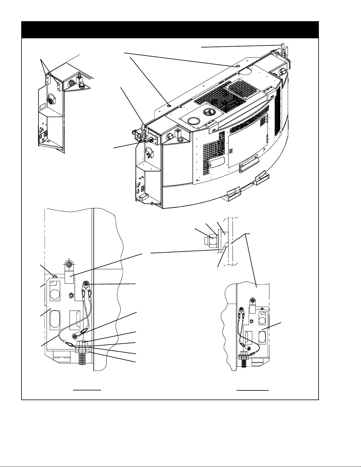
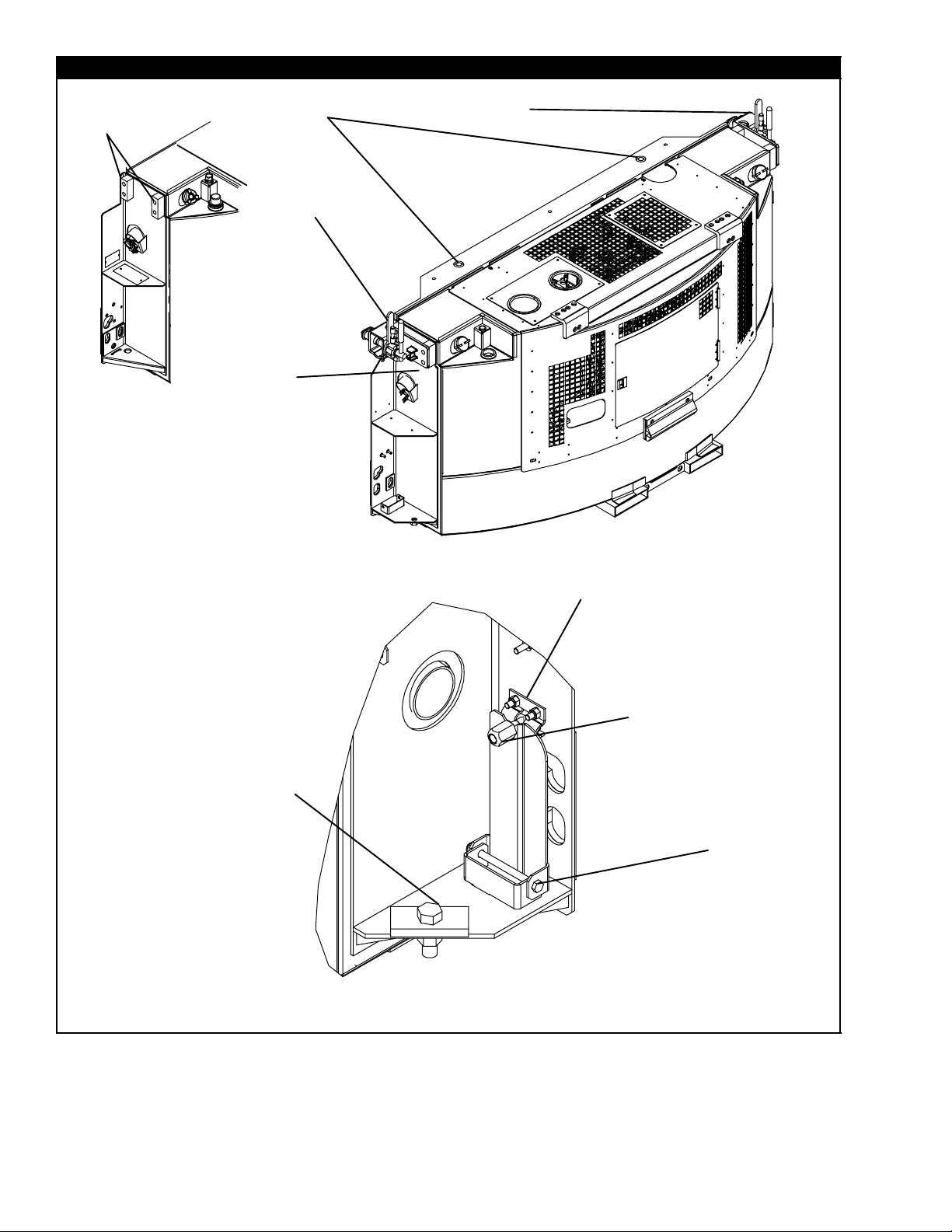
2 UNIT MOUNTING
2.a Unit Mounting
LEFT SIDE RIGHT SIDE
GENERATOR
SET WING
1
2
3
4
5
6
7
8
9
10
11
12
13
14
15
16
17
18
16
17
21
19
20
22
23
24
4 PLACES
BOTH
SIDES
25
BOTH
SIDES

3 T-272PL
2.a Unit Mounting - Common Parts
Item Part Number Description Qty
1 69GC15-492 Screw Assembly - Includes: 2
2 34-00662-18 Washer,Flat-SST 4
3 69GC15-1252 Washer, Retaining - SST 2
4 44-50005-00 Lanyard Assembly 4
5 66U1-1571-20 Grommet 2
6 68-12227-00 Plate (Left Hand) 1
7 68-12227-01 Plate (Right Hand) 1
8 69GC15-1212 Plate, Adjustable Mounting 2
9 66U1-5321-7 Washer, Flat, 1/4 - SST 4
10 34-00667-61 Locknut, 1/4-20 UNC-2B - SST 4
11 69GC15-3022 Bracket, Retaining Lever 2
12 34-01219-01 Spacer 2
13 34-01219-02 Spacer 2
14 34-01264-12 Washer, Flat, 5/16 - SST 2
15 34-00667-12 Locknut, 5/16-18 - SST 2
16 66U1-5321-2 Washer, Flat, #8 - SST 6
17 34-00667-08 Locknut, #8-32 - SST 4
18 66U1-5371 Screw, Hex Head, #8-32 x 1/2 Lg. - SST 2
2.a.1 Unit Mounting - Pin Mount
Item Part Number Description Qty
19 69GC15-1602 Pin, Unit Mounting 2
2.a.2 Unit Mounting - Clamp Mount
Item Part Number Description Qty
20 44-00362-02 Clamp, Unit Mounting (Road Side) (Welded) 1
21 44-00362-03 Clamp, Unit Mounting (Curb Side) (Welded) 1
22 34-06170-08 Screw , Socket Hd. Cap, 5/8-11 x 1.75 Lg. 8
23 66U1-5321-9 Washer, Flat, 5/8 - SST 8
24 66U1-5331-8 Washer, Lock, 5/8 8
2.a.3 Unit Mounting - Pin Mount With Clamp Provision
Item Part Number Description Qty
- 76-00707-00 Kit, Clamp - Field Installation 1
19 69GC15-1602 Pin, Unit Mounting 2
25 48-00309-00 Block, Mounting 4
4T-272PL
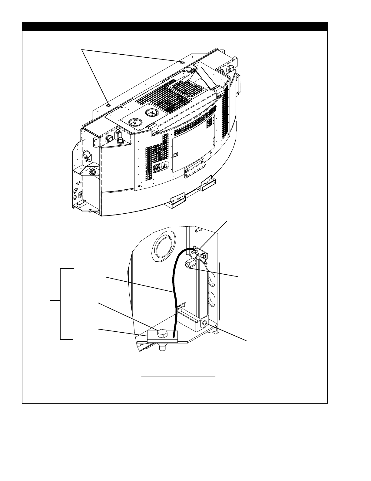
2.b Unit Mounting
4 PLACES
BOTH SIDES
BOTH
SIDES
3
4
9
10
11
12
13
14
15
16
1
2
5
6
7
8
LEFT AND RIGHT SIDE
RIGHT SIDE SHOWN
LEFT SIDE
RIGHT SIDE
OR
5 T-272PL
2.b Unit Mounting - Common Parts
Item Part Number Description Qty
1 34-06149-03 Screw, Cap Hex Head, 3/4-10 x 2.25 Lg. 2
2 68-12996-01 Plate, Spacer - See NOTE 2
3 68-12997-00 Bracket, Mounting - See NOTE 2
4 34-00667-12 Locknut, 5/16-18 - SST 4
5 34-00667-13 Locknut, 3/8-18 - SST 2
6 34-06200-00 Screw, Cap Hex Head, 3/8-16 x 4.88 Lg. 2
7 34-06201-00 Bolt, T-head, 1/2-13 x 2.75 Lg. 2
8 34-06207-00 Knob, 1/2-13 2
9 68-12998-01 Retainer, Left Side - See NOTE 1
10 68-12998-00 Retainer , Right Side - See NOTE 1
2.b.1 Unit Mounting - Pin Mount
Item Part Number Description Qty
11 69GC15-1602 Pin, Unit Mounting 2
2.b.2 Unit Mounting - Clamp Mount
Item Part Number Description Qty
12 44-00362-02 Clamp, Unit Mounting (Road Side) (Welded) 1
13 44-00362-03 Clamp, Unit Mounting (Curb Side) (Welded) 1
14 34-06170-08 Screw , Socket Hd. Cap, 5/8-11 x 1.75 Lg. 8
15 66U1-5331-8 Washer, Lock, 5/8 8
2.b.3 Unit Mounting - Pin Mount With Clamp Provision
Item Part Number Description Qty
- 76-00707-00 Kit, Clamp - Field Installation 1
11 69GC15-1602 Pin, Unit Mounting 2
16 48-00309-00 Block, Mounting 4
NOTE: See page v for painted parts color system.
6T-272PL
2.c Unit Mounting - Pin Mount
1
14
15
2
3
4
5
6
11
12
13
LEFT AND RIGHT SIDE
RIGHT SIDE SHOWN
OR
RIGHT SIDE
LEFT SIDE
7
8
9
10

7 T-272PL
2.c Unit Mounting - Pin Mount
Item Part Number Description Qty
1 69GC15-1602 Pin, Unit Mounting 2
2 68-12997-00 Bracket, Mounting - See NOTE 2
3 34-00667-12 Locknut, 5/16-18 - SST 4
4 34-06201-00 Bolt, T-head, 1/2-13 x 2.75 Lg. 2
5 34-06207-00 Knob, 1/2-13 2
6 74-00226-00 Lower Mounting Block 2
7 48-00354-00 Spacer, Plate 1
8 44-00402-00 Tether Assy 1
9 34-06149-03 Screw, Cap Hxhd, 3/4-10 X 2.25 1
10 34-06229-00 Bolt, Shoulder 1
11 34-06205-00 Washer, Retaining 1
12 34-00667-13 Locknut, 3/8-18 - SST 2
13 34-06200-00 Screw , Cap Hex Head, 3/8-16 x 4.88 Lg. 2
14 68-12998-00 Retainer , Right Side - See NOTE 1
15 68-12998-01 Retainer , Left Side - See NOTE 1
NOTE: See page v for painted parts color system.
8T-272PL
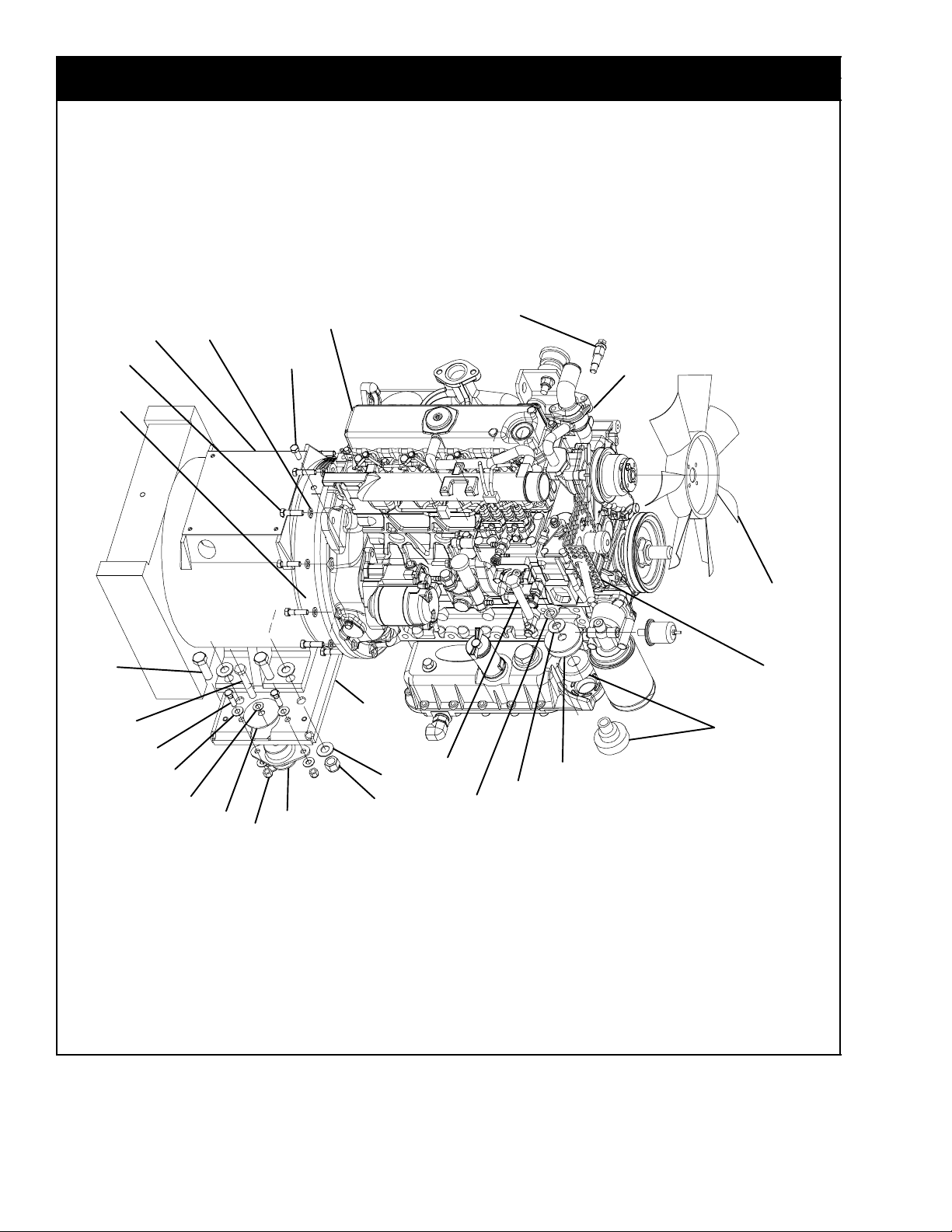
3 UNIDRIVE
3.a Unidrive Assembly - With And Without Throttle Guard
30
31
6
7
8
9
10
11
12
13
14
15
16
17
18
19
20
21
22
23
24
25
6
7
26
11
29
1
2
3
4
5
 Loading...