


52C 52Cand 52P
SERIES
OWNER’S MANUAL
PACKAGED TERMINAL AIR CONDITIONERS
AND HEAT PUMPS
7,000-15,000 Btuh
CONTENTS
Page
GENERAL. . . . . . . . . . . . . . . . . . . . . . . . . . . . . . . . . . . . . . . 2
UNIT INSPECTION . . . . . . . . . . . . . . . . . . . . . . . . . . . . . 2,3 FRONT PANEL . . . . . . . . . . . . . . . . . . . . . . . . . . . . . . . . 2
ELECTRICAL DATA. . . . . . . . . . . . . . . . . . . . . . . . . . . . . . 4 ALL UNITS. . . . . . . . . . . . . . . . . . . . . . . . . . . . . . . . . . . . 4 VOLTAGE SUPPLY . . . . . . . . . . . . . . . . . . . . . . . . . . . . . 4
INSTALLATION . . . . . . . . . . . . . . . . . . . . . . . . . . . . . . . .5-8 CHASSIS INSTALLATION . . . . . . . . . . . . . . . . . . . . . . 5
WALL THERMOSTAT INSTALLATION . . . . . . . . . . . 8
OPERATION . . . . . . . . . . . . . . . . . . . . . . . . . . . . . . . . . .9,10 COMFORT CONTROLS. . . . . . . . . . . . . . . . . . . . . . . . . 9 OPERATING CONTROLS . . . . . . . . . . . . . . . . . . . . . . 10 OPERATING MODES. . . . . . . . . . . . . . . . . . . . . . . . . . 10
Page
CARE AND MAINTENANCE . . . . . . . . . . . . . . . . . 11,12
INDOOR-AIR INLET FILTERS . . . . . . . . . . . . . . . . . . 11
EXTERNAL PARTS . . . . . . . . . . . . . . . . . . . . . . . . . . . . 12 INTERNAL PARTS . . . . . . . . . . . . . . . . . . . . . . . . . . . . 12
PREVENTATIVE MAINTENANCE. . . . . . . . . . . . . . . . 13
TROUBLESHOOTING. . . . . . . . . . . . . . . . . . . . . . . . . . . 14 ACCESSORIES. . . . . . . . . . . . . . . . . . . . . . . . . . . . . . . . . . 15
1•800•894•6449 (in USA and Canada)
For Service/Technical Assistance
1•800•830•8600 (Mexico)
Manufacturer reserves the right to discontinue, or change at any time, specifications or designs without notice and without incurring obligations.
Book |
1 |
4 |
PC 132 |
Catalog No. 535-20066 |
Printed in U.S.A. |
Form 52C,P-2SO |
Pg 1 |
10-04 |
Replaces: 52C,P-1SO |
Tab |
9a |
11a |
|
|
|
|
|
|
|

GENERAL
Thank you for choosing Carrier! You can feel confident in your selection because the same pride in craftsmanship and engineering knowledge that goes into Carrier equipment at the Astrodome in Texas, the Sistine Chapel in Rome, the US Capitol Hall of Congress, and thousands of other installations worldwide has gone into the construction of this unit.
The Carrier package terminal air conditioners and heat pumps provide a high standard of quality in performance, workmanship, durability and appearance as they heat and cool the occupied air space year round.
This manual provides information for ease of installation, operation and maintenance of the 52C and 52P units. The following units are covered in this manual (see Figure 1 for additional unit information):
52CE 60 Hz cooling with electric heat units
52CQ 60 Hz cooling, electric heat, and heat pump units 52PE 60 Hz cooling with electric heat units
52PQ 60 Hz cooling, electric heat, and heat pump units 52PC 60 Hz cooling only units
All models are designed for through-the-wall installation. Separate installation instructions are included
MODEL 52PQA312301AA
SERIAL |
3701X11520 |
|
|||
DATE OF MFG. |
09/12/2001 |
||||
VOLT RANGE |
187-253 |
|
|||
|
|
|
|
|
|
VOLTS |
230/208 |
|
|
|
|
PH 1 |
|
|
HZ |
|
60 |
MIN CKT AMPACITY |
19.3 |
||||
|
|
|
|
|
|
R-22 OZ |
34 |
|
|
|
|
DESIGN PSIG 350 HIGH SIDE, 150 LOW SIDE
COOLING
BTU/HR 12,100/12,000
AMPS |
4.8/5.3 |
|
|
WATTS |
1100/1100 |
|
|
EER |
11.0/10.9 |
|
|
COMP |
RLA |
|
6.1 |
|
|
|
|
LRA |
|
29 |
|
|
|
||
FAN |
FLA |
|
0.75 |
MOTOR |
HP |
|
1/8 |
HEATING
BTU/HR 10,800/10,700
AMPS 15.6/14.5
WATTS 3570/2997
COP 3.2/3.2
AMPS 14.8/13.7
HEATER
WATTS 3400/2850
WATER
BTU/HR
STEAM
|
|
AMP |
CANADIAN INSTALLATION |
||||
USE |
20 |
MAX FUSE |
MAX BREAKER |
||||
TIME DELAY FUSE |
|||||||
OR HACR TYPE |
20 |
AMP |
|
20 |
AMP |
||
CIRCUIT BREAKER |
|
|
|
|
|
||
|
|
|
|
|
|||
C |
US |
FIGURE 1 — SAMPLE DATA INFORMATION PLATE
with all accessory components. See Accessories section on page 15 for complete listing of accessories.
UNIT INSPECTION
Examine unit for damage incurred during shipment. File a claim immediately with the transit company if damage is found.
The data information plate (Figure 1) lists the model number, voltage ranges, and other important electrical information about this product. Reading and understanding this material is important for proper use of this unit. To access the information plate, the front panel must be removed; see Figure 2.
FRONT PANEL
Remove front panel from unit by grasping the panel firmly at the center top and center bottom. Pull the panel upward at the bottom and forward at the top to release magnetic latches and partition hooks. See Figure 2.
NOTE: Front panel may be secured to chassis with
2 screws located behind indoor air inlet filters. In order to remove these screws, the filters must be removed first. Refer to page 11 in this manual for instructions on removing indoor air inlet filters.
IMPORTANT: The front panel has to be off the unit to complete future checks and installation procedures. Do not reinstall front panel at this time.
Using Figures 1 and 3 as reference, verify that the packaged terminal product ordered will operate properly in your facility. If you do not understand the information given or have questions about the product, please call your local dealer or distributor.
FIGURE 2 — REMOVING FRONT PANEL
Replacement Package Terminal Air Conditioner, CLASSIFIED BY UNDERWRITERS LABORATORIES INC., AS TO ELECTRIC
SHOCK, FIRE AND CASUALTY
HAZARDS ONLY. FOR FIELD INSTALLATION WITH EXISTING WALL SLEEVES, OUTDOOR LOUVERS, AND INDOOR PANELS AS SPECIFIED ON THE PRODUCT.
2

52 PE A 3 12 3 0 1 AA
Series Designation
PTAC (Packaged Terminal Air Conditioner)
Comfort Series
CE – Cooling with Electric Heat CQ – Heat Pump
Premier Series
PC – Cooling Only
PE – Cooling with Electric Heat PQ – Heat Pump
Latest Revision
A – Z
Electric Heater Size
2 – 2.3 kW
3 – 3.4 kW
5 – 5.0 kW
Cooling Capacity (nominal)
07 – 7,000 Btuh
09 – 9,000 Btuh
12 – 12,000 Btuh
15 – 15,000 Btuh
Chassis Options
AA – Standard
CP – Corrosion Protection
RC – Wall Thermostat Control (Not available on cooling only units)
RP – Wall Thermostat Control with Corrosion Protection (Not available on cooling only units)
Packaging
1 – Domestic
Non-Performance
Changes 0-9
Electrical Data
3– 230/208-v, 60 Hz
4– 265-v, 60 Hz
FIGURE 3 — MODEL NUMBER NOMENCLATURE
To install the front panel, follow the procedure outlined below:
Replace the unit front panel.
1.Hold the front panel firmly at the center top and center bottom at a 5 to 10 degree angle from vertical.
2.Place the top of the front panel onto the unit making sure the top engagement posts have engaged the slots on the unit. Front panel should be flat against the top of the unit.
3.Gently lower the front panel onto the chassis, ensuring that the power cord (or conduit) is routed through the front panel notch. Magnetic latches at bottom of front panel will secure the front panel to the unit.
To install locking feature on front panel, be sure front panel is already installed on unit and follow the steps below:
NOTE: Two field-supplied no. 8, 1/2-in. sheet metal screws are required to secure front panel to chassis.
1.Remove both indoor air inlet filters to expose front panel engagement holes. See Figure 4.
2.Secure front panel to chassis by attaching the field-supplied screws into engagement holes. Do not over tighten.
3.Replace both indoor air inlet filters.
NOTE: Front panel alignment may have to be adjusted slightly to line with chassis.
TOP PARTITION
DISCHARGE |
ENGAGEMENT |
FRONT PANEL |
DECK |
HOLE |
SLOT |
FIGURE 4 — FRONT PANEL INSTALLATION
WITH LOCKING FEATURE
3

ELECTRICAL DATA
ELECTRICAL SHOCK HAZARD
DO NOT alter cord or plug, and DO NOT use an extension cord. Personal injury or damage to the unit may result.
Be sure that your outlet matches the appropriate blade configuration of the supplied plug and that it is within reach of the service cord. A hardwire kit is available as an accessory to change cord-connected units to hardwired units. (See Accessories table on page 15.)
IMPORTANT: All standard cord-connected 265-v units will require a field-installed electrical subbase accessory.
ALL UNITS
■ WIRE SIZE — Use recommended wire size given in Table 1 and install a single branch circuit. All wiring must comply with local and national codes. All units are designed to operate off single branch circuits only.
NOTE: Use copper conductors only.
■ GROUNDING — For safety and protection, the unit is grounded through the service cord plug or through separate ground wire provided on hardwired units. Be sure that the branch circuit or general purpose outlet is grounded.
TABLE 1 — SUGGESTED BRANCH CIRCUIT
WIRE SIZES*
NAMEPLATE AMPS |
AWG WIRE SIZE† |
7.0 to 12 |
14 |
12.1 to 16 |
12 |
16.1 to 24 |
10 |
LEGEND |
|
AWG — American Wire Gage
*Single circuit from main box.
†Based on copper wire at 60 C temperature rating.
VOLTAGE SUPPLY
Check voltage supply at outlet. For satisfactory results, the voltage range must always be within the ranges found on the data information plate
(shown in Figure 1).
■CORD-CONNECTED UNITS — The 250-v fieldsupplied outlet must match the plug for the standard 208/230-v units and be within reach of the service cord. The standard cord-connected 265-v units require an accessory electrical subbase for operation. See Accessories table, page 15, for subbase selection. Refer to Table 2 for proper receptacle and fuse type.
■POWER CORD PROTECTION — The power cord for the 230/208-v unit provides both personal shock protection and power cord fire prevention. Unit power automatically disconnects when unsafe conditions are detected. Power to the unit can be restored by pressing the RESET button on plug head.
Upon completion of unit installation for 230/208-v models, an operational check should be performed using the TEST/RESET buttons on the plug head. See Figure 5.
NOTE: The 265-v models do not incorporate this feature as they require use of the electrical subbase accessory.
TABLE 2 — RECEPTACLES AND FUSE TYPES — 250,265 VOLTS
RECEPTACLE |
|
|
|
|
|
|
|
|
|
|
|
|
|
|
|
|
|
|
|
|
|
|
|
|
|
|
|
|
|
|
|
|
|
|
|
|
|
|
|
|
|
|
|
|
|
|
|
|
|
|
|
|
|
|
|
|
|
|
|
|
|
|
|
|
|
|
|
|
|
|
|
|
|
|
|
|
|
|
|
|
|
|
|
|
|
|
|
|
|
|
|
|
|
|
|
|
|
|
|
|
|
|
|
|
|
|
|
|
|
|
|
|
|
|
|
|
|
|
|
|
|
|
|
|
|
|
|
|
15 Amps |
20 Amps |
30 Amps |
15 Amps |
20 Amps |
30 Amps |
|||||||||||||||||||||||||
RATED VOLTS |
250 |
|
250 |
|
250 |
|
265 |
265 |
265 |
|
|||||||||||||||||||||
TIME-DELAY TYPE |
15 |
|
20* |
|
30 |
|
15 |
20 |
30 |
|
|
||||||||||||||||||||
FUSE (or HACR Circuit Breaker) |
|
|
|
|
|
||||||||||||||||||||||||||
|
|
|
|
|
|
|
|
|
|
|
|
|
|
|
|
|
|
|
|
|
|
|
|
|
|
|
|
|
|
|
|
LEGEND |
|
|
|
|
|
|
|
|
|
|
|
|
|
|
|
|
|
|
|
|
|
|
|
|
|
|
|
|
|
|
|
HACR — Heating, Air Conditioning, Refrigeration |
|
|
|
|
|
|
|
|
|
|
|
|
|
|
|
|
|
|
|
|
|
|
|
|
|
||||||
*May be used for 15-amp applications if fused for 15 amp. |
|
|
|
|
|
|
|
|
|
|
|
|
|
|
|
|
|
|
|||||||||||||
4
INSTALLATION
CHASSIS INSTALLATION
Units are shipped without a sleeve. In applications where unit is a replacement, it is recommended that a Carrier sleeve and grille be used.
The 52C and 52P units can retrofit General Electric, Amana, Trane, and Friedrich sleeves/grilles (be sure outdoor grille is installed on the sleeve). See Table 3 for details. Carrier Corporation must approve any other retrofit application.
For competitive retrofit applications, be sure that the foam seals (factory-installed on the tube sheets) provide a good seal between the outdoor grille and outdoor coil tube sheets. These foam seals provide a barrier to separate outdoor coil leaving air from mixing with the outdoor incoming air (known as air recirculation).
See Figure 5.
For retrofit applications, foam seals on outdoor coil tube sheets must make a seal between the coil and the grille or loss of performance and premature damage to the major components can result.
TABLE 3 — RETROFIT WALL SLEEVES
MANUFACTURER |
WALL SLEEVE PART NUMBER |
General Electric |
Metal Sleeve RAB71 |
|
Plastic Sleeve RAB77 |
Amana |
Metal Sleeve WS900B |
Trane |
Metal Sleeve SLV149 |
Friedrich |
T-Series Metal 111/2-in. deep wall sleeve* |
|
Standard depth wall sleeve 16 x 42 x 133/4-in. |
|
PXWS |
*FR-SLEEVE-EXT accessory is required for retrofit into Friedrich (T-Series) wall sleeves.
INDOOR-AIR |
DISCHARGE WIRE SCREEN |
OUTDOOR |
COIL TUBE |
INLET |
GRILLE |
ORIFICE |
SHEETS |
FILTERS |
|
|
|
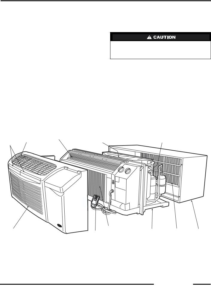
TESTING
|
INDOOR |
|
|
|
FRONT |
COIL |
BASEPAN |
OUTDOOR |
WALL |
PANEL |
PLUG TEST/ |
|
GRILLE |
SLEEVE |
|
RESET BUTTONS |
|
|
|
FIGURE 5 — UNIT COMPONENTS
5
■ COMPETITIVE SLEEVE PREPARATION
IMPORTANT: Inspect the wall sleeve thoroughly prior to installation. Manufacturer does not assume responsibility for costs or damages due to defects in the sleeve or improper installation.
Disconnect all power to unit to avoid possible electrical shock during installation.
Remove any existing foam baffles that are installed on the outdoor grille if present. See Figure 6.
GE Sleeves Only
Metal Wall Sleeve — Remove metal clip on mounting rail located on left, inside bottom of metal sleeve and discard. See Figure 7.
Plastic Sleeve — Remove bottom seal from plastic sleeve. See Figure 8.
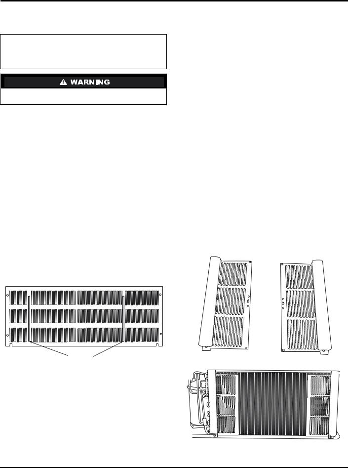
■ INSTALLATION OF A CARRIER WALL SLEEVE
USING A NON-CARRIER GRILLE
This application has become more common due to pre-manufactured windows with built-in grilles or renovations where a Carrier sleeve is used with an existing non-Carrier grille.
Use of a Carrier wall sleeve with a non-Carrier grille requires installation of an Accessory Baffle Kit, which ensures a good seal between the unit and exterior grille and prevents air recirculation. (See Figures 9 and 10.) Air recirculation is a large contributor to performance loss and premature damage to major components.
BAFFLES
FIGURE 6 — REMOVE EXISTING BAFFLES ON COMPETITIVE OUTDOOR GRILLES
FIGURE 7 — REMOVE METAL CLIP ON
GE METAL SLEEVE
FIGURE 8 — REMOVE BOTTOM SEAL FROM
GE PLASTIC SLEEVE
FIGURE 9 — ACCESSORY BAFFLE KIT
FIGURE 10 — INSTALLATION COMPLETE
6

■ INSTALL CHASSIS IN SLEEVE (See Figures 11 to
13)
1.Inspect foam gaskets (top, bottom, both sides) on chassis. Replace foam gaskets if torn or missing.
IMPORTANT: The gaskets combine with the sleeve face to create a weather barrier. If the chassis is installed in a non-Carrier sleeve, this weather barrier may not be effective.
Chassis weighs up to 150 lb. For personal protection, seek help when lifting the unit. Lift unit by holding unit basepan.
2.If retrofitting into a GE, Amana, Trane, or Friedrich wall sleeve/grille, remove any existing foam seals from competitive manufacturer’s grille before installing unit.
3.Remove shipping tape from vent door. See Figure 11.
Failure to remove shipping tape will prevent fresh air vent door from opening and may result in damage to the vent door cable.
4.Carefully remove power cord packing material and discard.
5.Lift chassis level with wall sleeve.
6.Slide chassis into wall sleeve until foam gaskets rest firmly against front of wall sleeve. See Figure 12.
7.Screw chassis to wall sleeve with four 13/4-in. long screws taped to the control box. Screw holes are located on both sides of the mounting angles of the chassis. For Carrier wall sleeves, use the top-most and bottom-most screw holes. For competitive wall sleeves, line up the correct attachment holes on the chassis with the holes in the sleeves. See Figure 13.
SIDE |
TOP |
FACTORY-INSTALLED |
GASKET |
GASKET |
FOAM SEALS |
BOTTOM |
COIL TUBE |
GASKET |
SHEETS |
FIGURE 12 — UNIT GASKETS
AND TUBE SHEETS
TOP SCREW HOLE
(CARRIER SLEEVE)
COMPETITIVE
MANUFACTURER
SLEEVE
ATTACHMENT
HOLES
 BOTTOM SCREW HOLE
(CARRIER SLEEVE)
FIGURE 13 — CHASSIS MOUNTING
VENT |
SHIPPING |
VENT DOOR |
DOOR |
TAPE |
CABLE |
FIGURE 11 — LOCATION OF SHIPPING TAPE
ON VENT DOOR
7

WALL THERMOSTAT INSTALLATION
The following instructions apply to RC and RP units only.
NOTE: Carrier thermostats are recommended. See Accessories section.
IMPORTANT: Only trained, qualified personnel and service mechanics should install electrical accessories on Carrier 52C and 52P series products per Carrier’s installation instructions. Please contact your local electrical contractor, dealer, or distributor for assistance.
■THERMOSTAT WIRE ROUTING — Thermostat wire is field supplied. Recommended wire gage is 18 to 20 gage solid thermostat wire. Thermostat wire should always be routed around or under, NEVER through, the wall sleeve. The wire should then be routed behind the front panel to the easily accessible terminal connector. See Figures 14 and 15.
■INSTALL THERMOSTAT — All remote control units.
1.Check to be sure power to unit is disconnected.
2.Pull terminal connector to remove.
NOTE: Terminal connector can be removed and replaced to simplify thermostat wiring.
3.Connect wires from terminals on the thermostat to terminals on chassis terminal board connector. See Figures 15 and 16.
FAN SPEED |
|
FAN SPEED |
|
LO |
HI |
SELECTOR |
|
SWITCH |
|||
|
|
 TERMINAL
CONNECTOR
 R
R
Y
 W
W
 G
G
 O
O
 C
C
THERMOSTAT
WIRE (FIELD
SUPPLIED)
POWER |
THERMOSTAT |
|
CORD |
||
|
FIGURE 14 — CONTROL BOX TERMINAL CONNECTOR FOR WALL THERMOSTAT MODELS
4.Reinstall terminal connector.
5.Restore power to unit.
NOTE: Refer to thermostat installation instructions for details on installing thermostat.
NOTE: Fan speed is user-selectable from the control panel on the unit.
 R
R
 Y
Y
 W
W
 G
G
 O
O
C
FIGURE 15 — TERMINAL CONNECTOR REMOVAL AND REPLACEMENT
|
R |
|
G |
TYPICAL |
Y |
WALL |
|
THERMOSTAT |
W |
O |
SEE |
|
NOTE #1 |
||
|
||
C SEE |
||
|
NOTE #2 |
|
TERMINAL |
|
|
BLOCK |
|
|
NOTES:
1.Use terminal “O” for heat pump connection only.
2.Terminal C (common) is typically only required for digital thermostats.
3.See table below for terminal descriptions.
TERMINAL |
DESIGNATION |
R |
24 VAC |
G |
Fan |
Y |
Compressor |
W |
Electric Heat |
O |
Reversing Valve |
C |
Common |
FIGURE 16 — WIRING CONNECTIONS
8
OPERATION
IMPORTANT: When unit is first started, high humidity conditions can cause condensation to form on discharge grille. Keep doors and windows closed. Room humidity decreases and moisture evaporates.
COMFORT CONTROLS
■ADJUST AIRFLOW DIRECTION — The discharge air grille is mounted on the front panel so that the air discharges forward. If upward discharge is required, remove the grille by removing screws on back of front panel. Rotate grille 180 degrees and reinstall on the front panel.
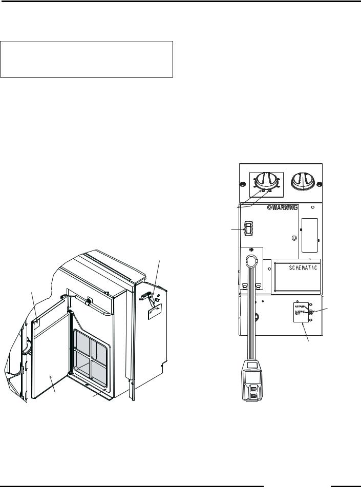
■ADJUST VENT — The vent handle is on the left side of the unit. Turn handle to open or close vent. Vent will remain in last desired position until handle is turned again. Magnet will ensure positive closure. See Figure 17.
■SETTING TEMPERATURE LIMITS — Setting temperature limits on the unit provides the user a restricted range of temperature control. See Figure 18.
NOTE: This adjustment is optional and is not applicable to remote control units.
VENT HANDLE
MAGNET
CLOSE
|
N |
O |
PE |
VENT VENT
DOOR FILTER
FIGURE 17 — VENT DOOR
The temperature limits are factory set to full range, which is 60 F to 90 F. To set restricted rotation of the temperature control knob:
1.Remove front panel.
2.Remove temperature control knob to expose temperature limiter.
3.Remove standoff pins from the 60 F and 90 F indicator holes.
4.Replace standoff pin in hole for desired minimum temperature.
5.Replace standoff pin in hole for desired maximum temperature.
6.Reinstall temperature control knob.
7.Reinstall front panel.
NOTE: Temperature indicators stamped on temperature limiter are approximate and represent degrees F.
|
|
75 |
80 |
|
70 |
|
|
|
85 |
|
65 |
|
90 |
60 |
TEMPERATURE
CONTROL
STANDOFF
PINS
CON
CYC
FAN CYCLE
SWITCH
SET
SCREW
OUTDOOR THERMOSTAT (HEAT PUMP UNITS ONLY)
SLIAF E V OBAT SETS |
I ESU T O NO D |
||
|
|
. |
FROEUS |
4.PSERSRESETBTTUONNIAGA |
|||
T |
INU |
THGLI. |
OHSUDL |
3.ERPSSSETTTUBTNO |
|||
|
|
CERETPALEC. |
|
|
|
2.PLUGINTOPWOER |
|
|
1.ERPSSSERETTUBT.NO |
||
|
|
GINTSET |
|
FIGURE 18 — OPERATING CONTROLS
9

OPERATING CONTROLS
The following controls are located on the front of the control box door, under front panel. To obtain access to operating controls, remove the unit front panel as shown on page 2. See Figure 18.
■ FAN CYCLE SWITCH — (Typically available at wall thermostat on RC or RP units.) This allows the fan to operate in two modes:
CON (Continuous) — This setting allows the fan to run continuously, circulating air even when the temperature setting has been satisfied. This switch helps to maintain the room temperature closer to the thermostat setting. Use this switch position when maximum comfort is desired. This is the factory default setting.
CYC (Cycle) — This setting allows the fan to cycle on and off with the compressor during heating or cooling. The fan stops when the temperature setting is satisfied. This results in longer unit off-time and wider variations in room temperature and humidity.
■ OUTDOOR THERMOSTAT (52CQ and 52PQ HEAT PUMP UNITS ONLY) — If the setscrew is left at the factory setting (in the heat pump position), the unit will operate in the reverse cycle heating mode. See Figure 18. When the temperature of the outdoor coil reaches 20 F (approximately 35 F outdoor air temperature), the compressor will shut down as unit is no longer capable of adequate heating in heat pump mode. The electric heater then becomes the primary heating source. The electric heater remains on until the temperature of the outdoor coil reaches 40 F; then the electric heater is shut off and the compressor is energized. Once the compressor is energized, the heat pump again becomes the primary heating source.
To set unit to operate in electric heat mode only, turn the setscrew to the electric heat position. See Figure 18.
IMPORTANT: If setscrew on standard heat pump unit is set to electric heat mode operation, the compressor is disabled for both heating and cooling operations. If setscrew on heat pump unit with wall thermostat control is set to electric heat mode operation, the compressor will be disabled only for heating operation.
OPERATING MODES (See Figures 19
and 20.)
■OUTSIDE AIR — To bring outside air into occupied space, turn the vent handle to the full open position. See Figure 17.
■OFF — The OFF mode terminates unit operation.
■FAN— The FAN mode will circulate air in the space at high speed and at high or low speed for cooling only models.
■HIGH HEAT OR HIGH COOL — Select mode and rotate temperature knob to desired comfort level. This function provides maximum heating or cooling, and is recommended to raise or lower the room temperature quickly.
■LOW HEAT OR LOW COOL — Select mode and rotate temperature knob to desired comfort level. This function provides minimum heating or cooling with maximum dehumidification and quietest operation.
■FAN SPEED CONTROL FOR 52P AND 52C WALL THERMOSTAT MODELS — For maximum comfort, fan speed is user selectable at the unit. See Figure 20.
FIGURE 19 — 52P UNIT CONTROLS SHOWN |
FIGURE 20 — 52P UNIT WITH |
|
WALL THERMOSTAT CONTROL SHOWN |
|
(Blank Plate) |
10
CARE AND MAINTENANCE
In order to maintain proper performance of your packaged terminal air conditioner or heat pump, it is very
important that the fan and outdoor coil, the blower wheel, blower scroll, electric heater, and all drain passages are thoroughly cleaned at least once per year.
Carrier recommends that as a minimum, the cleaning should be conducted prior to the start of each heating season. The air inlet filters should be cleaned every month.
Depending on local conditions, more frequent cleaning of the unit may be required to ensure optimum performance and long operating life. Examples of these special conditions include areas where construction dust or heavy airborne dirt is found, or environments that
promote the growth of fungus.
FIGURE 21 — INDOOR-AIR INLET
FILTER REMOVAL
Some local conditions and environments can cause fungi to grow inside the air conditioner, especially on indoor blower section. Dried fungi, dirt and other foreign material are fire hazards. Be sure to clean unit according to the instructions that follow.
INDOOR-AIR INLET FILTERS
■ INDOOR-AIR INLET FILTERS should be cleaned once each month.
IMPORTANT: Filters may become clogged if not cleaned properly. Clogged filters will restrict airflow which may lead to severe component damage and efficiency loss.
■ CLEANING INDOOR-AIR INLET FILTER — Two interchangeable air filters are located on the backside of the front panel. Each can be removed and cleaned one at a time. To remove and clean the filter, follow the steps below:
1.Grasp filter with both hands.
2.Gently pull the filter up and away from the unit. See Figures 5 and 21.
3.To clean filter, use a vacuum or soft bristle brush with a small amount of mild detergent.
NOTE: If detergent is used, remove any detergent residue with a gentle stream of clean water.
4.Allow filters to air dry.
5.Re-insert dry filters back into front panel.
Additional filters are available in multi-packs. Refer to
Accessories section.
11
 Loading...