


Carrier
Transicold
Container
Refrigeration
Model 69NT20-531-300
Streamline Scroll
Operation |
& Service |
T-309 Rev A

OPERATION AND SERVICE MANUAL CONTAINER REFRIGERATION UNIT
MODEL 69NT20-531-300 Streamline Scroll
Carrier Transicold. A member of the United Technologies Corporation family. Stock symbol UTX.
Carrier Transicold Divsion, Carrier Corporation, P.O. Box 4805, Syracuse, N.Y. 13221 U. S. A.
ã 2002 CarrierCorporation D Printed in U. S. A. 07/02
SAFETY SUMMARY
GENERAL SAFETY NOTICES
The following general safety notices supplement the specific warnings and cautions appearing elsewhere in this manual. They are recommended precautions that must be understood and applied during operation and maintenance of the equipment covered herein. The general safety notices are presented in the following three sections labeled: First Aid, Operating Precautions and Maintenance Precautions. A listing of the specific warnings and cautions appearing elsewhere in the manual follows the general safety notices.
FIRST AID
An injury, no matter how slight, should never go unattended. Always obtain first aid or medical attention immediately.
OPERATING PRECAUTIONS
Always wear safety glasses.
Keep hands, clothing and tools clear of the evaporator and condenser fans.
No work should be performed on the unit until all circuit breakers, start-stop switches are turned off, and power supply is disconnected.
Always work in pairs. Never work on the equipment alone.
In case of severe vibration or unusual noise, stop the unit and investigate.
MAINTENANCE PRECAUTIONS
Beware of unannounced starting of the evaporator and condenser fans. Do not open the condenser fan grille or evaporator access panels before turning power off, disconnecting and securing the power plug.
Be sure power is turned off before working on motors, controllers, solenoid valves and electrical control switches. Tag circuit breaker and power supply to prevent accidental energizing of circuit.
Do not bypass any electrical safety devices, e.g. bridging an overload, or using any sort of jumper wires. Problems with the system should be diagnosed, and any necessary repairs performed, by qualified service personnel.
When performing any arc welding on the unit or container, disconnect all wire harness connectors from the modules in both control boxes. Do not remove wire harness from the modules unless you are grounded to the unit frame with a static safe wrist strap.
In case of electrical fire, open circuit switch and extinguish with CO2 (never use water).
UNIT LABEL IDENTIFICATION
To help identify the label hazards on the unit and explain the level of awareness each one carries, an explanation is given with the appropriate consequences:
DANGER - means an immediate hazard which WILL result in severe personal injury or death.
WARNING - means to warn against hazards or unsafe conditions which COULD result in severe personal injury or death.
CAUTION - means to warn against potential hazard or unsafe practice which could result in minor personal injury, product or property damage.
SPECIFIC WARNING AND CAUTION STATEMENTS
The statements listed below are applicable to the refrigeration unit and appear elsewhere in this manual. These recommended precautions must be understood and applied during operation and maintenance of the equipment covered herein.
WARNING
Beware of unannounced starting of the evaporator and condenser fans. The unit may cycle the fans and compressor unexpectedly as control requirements dictate.
WARNING
Do not attempt to remove power plug(s) before turning OFF start-stop switch (ST), unit circuit breaker(s) and external power source.
WARNING
Make sure the power plugs are clean and dry before connecting to any power receptacle.
Safety-1 |
T-309 |
WARNING
Make sure that the unit circuit breaker(s) (CB-1 & CB-2) and the START-STOP switch (ST) are in the “O” (OFF) position before connecting to any electrical power source.
WARNING
Never use air for leak testing. It has been determined that pressurized, mixtures of refrigerant and air can undergo combustion when exposed to an ignition source.
WARNING
Make sure power to the unit is OFF and power plug disconnected before replacing the compressor.
WARNING
Before disassembly of the compressor make sure to relieve the internal pressure very carefully by slightly loosening the couplings to break the seal.
WARNING
Oakite No. 32 is an acid. Be sure that the acid is slowly added to the water. DO NOT PUT WATER INTO THE ACID - this will cause spattering and excessive heat.
WARNING
Wear rubber gloves and wash the solution from the skin immediately if accidental contact occurs. Do not allow the solution to splash onto concrete.
WARNING
Always turn OFF the unit circuit breakers (CB-1 & CB-2) and disconnect main power supply before working on moving parts.
WARNING
Make sure power to the unit is OFF and power plug disconnected before removing capacitor(s).
WARNING
With power OFF discharge the capacitor before disconnecting the circuit wiring.
WARNING
Do not use a nitrogen cylinder without a pressure regulator. Do not use oxygen in or near a refrigeration system as an explosion may occur.
WARNING
Do not open the condenser fan grille before turning power OFF and disconnecting power plug.
WARNING
The Unit Power Plug Must Be Disconnected To Remove Power From Circuit Breaker Cb1
CAUTION
Do not remove wire harnesses from controller modules unless you are grounded to the unit frame with a static safe wrist strap.
CAUTION
Unplug all controller module wire harness connectors before performing arc welding on any part of the container.
CAUTION
When condenser water flow is below 11 lpm (3 gpm) or when water-cooled operation is not in use, the CFS switch MUST be set to position ”1” or the unit will not operate properly.
CAUTION
Pre-trip inspection should not be performed with critical temperature cargoes in the container.
T-309 |
Safety-2 |
|
CAUTION
When Pre-Trip key is pressed, economy, dehumidification and bulb mode will be deactivated. At the completion of Pre-Trip activity, economy, dehumidification and bulb mode must be reactivated.
CAUTION
When a failure occurs during automatic testing the unit will suspend operation awaiting operator intervention.
CAUTION
When Pre-Trip test Auto 2 runs to completion without being interrupted, the unit will terminate pre-
trip and display “Auto 2” “end.” The unit will suspend operation until the user depresses the ENTER key!
CAUTION
To prevent trapping liquid refrigerant in the manifold gauge set be sure set is brought to suction pressure before disconnecting.
CAUTION
The scroll compressor achieves low suction pressure very quickly. Do not use the compressor to evacuate the system below zero psig. Never operate the compressor with the suction or discharge service
valves closed (frontseated). Internal damage will result from operating the compressor in a deep vacuum.
CAUTION
Use only Carrier Transicold approved Polyol Ester Oil (POE) - Mobil ST32 compressor oil with R-134a. Buy in quantities of one quart or smaller. When using this hygroscopic oil, immediately reseal.
Do not leave container of oil open or contamination will occur.
CAUTION
Take necessary steps (place plywood over coil or use sling on motor) to prevent motor from falling into condenser coil.
CAUTION
DO NOT disassemble piston from NEW suction modulating valve powerhead assembly. Doing so may result in damage to piston.
CAUTION
The unit must be OFF whenever a programming card is inserted or removed from the controller programming port.
CAUTION
Do not allow moisture to enter wire splice area as this may affect the sensor resistance.
Safety-3 |
T-309 |
|
|
TABLE OF CONTENTS |
|
PARAGRAPH NUMBER |
Page |
||
GENERAL SAFETY NOTICES . . . . . . . . . . . . . . . . . . . . . . . . . . . . . . . . . . . . . . . . . . . . . . . . . . . . . |
Safety-1 |
||
FIRST AID . . . . . . . . . . . . . . . . . . . . . . . . . . . . . . . . . . . . . . . . . . . . . . . . . . . . . . . . . . . . . . . . . . . . . . |
Safety-1 |
||
OPERATING PRECAUTIONS . . . . . . . . . . . . . . . . . . . . . . . . . . . . . . . . . . . . . . . . . . . . . . . . . . . . . . |
Safety-1 |
||
MAINTENANCE PRECAUTIONS . . . . . . . . . . . . . . . . . . . . . . . . . . . . . . . . . . . . . . . . . . . . . . . . . . |
Safety-1 |
||
UNIT LABEL IDENTIFICATION . . . . . . . . . . . . . . . . . . . . . . . . . . . . . . . . . . . . . . . . . . . . . . . . . . . |
Safety-1 |
||
SPECIFIC WARNING AND CAUTION STATEMENTS . . . . . . . . . . . . . . . . . . . . . . . . . . . . . . . . . |
Safety-1 |
||
INTRODUCTION . . . . . . . . . . . . . . . . . . . . . . . . . . . . . . . . . . . . . . . . . . . . . . . . . . . . . . . . . . . . . . . . . . . . . . . . . . . . . |
. 1-1 |
||
1.1 |
INTRODUCTION . . . . . . . . . . . . . . . . . . . . . . . . . . . . . . . . . . . . . . . . . . . . . . . . . . . . . . . . . . . . . |
. 1-1 |
|
1.2 |
CONFIGURATION IDENTIFICATION . . . . . . . . . . . . . . . . . . . . . . . . . . . . . . . . . . . . . . . . . . . . |
. 1-1 |
|
1.3 |
OPTION DESCRIPTIONS . . . . . . . . . . . . . . . . . . . . . . . . . . . . . . . . . . . . . . . . . . . . . . . . . . . . . . |
. 1-1 |
|
|
1.3.1 |
Battery . . . . . . . . . . . . . . . . . . . . . . . . . . . . . . . . . . . . . . . . . . . . . . . . . . . . . . . . . . . . . . . . . . . |
. 1-1 |
|
1.3.2 |
Dehumidification . . . . . . . . . . . . . . . . . . . . . . . . . . . . . . . . . . . . . . . . . . . . . . . . . . . . . . . . . . . |
. 1-1 |
|
1.3.3 |
Control Box . . . . . . . . . . . . . . . . . . . . . . . . . . . . . . . . . . . . . . . . . . . . . . . . . . . . . . . . . . . . . . . |
. 1-1 |
|
1.3.5 |
Pressure Readout . . . . . . . . . . . . . . . . . . . . . . . . . . . . . . . . . . . . . . . . . . . . . . . . . . . . . . . . . . . |
. 1-1 |
|
1.3.6 |
Interrogator . . . . . . . . . . . . . . . . . . . . . . . . . . . . . . . . . . . . . . . . . . . . . . . . . . . . . . . . . . . . . . . |
. 1-1 |
|
1.3.7 |
Remote Monitoring . . . . . . . . . . . . . . . . . . . . . . . . . . . . . . . . . . . . . . . . . . . . . . . . . . . . . . . . . |
. 1-1 |
|
1.3.8 |
Communications . . . . . . . . . . . . . . . . . . . . . . . . . . . . . . . . . . . . . . . . . . . . . . . . . . . . . . . . . . . |
. 1-1 |
|
1.3.9 |
Compressor . . . . . . . . . . . . . . . . . . . . . . . . . . . . . . . . . . . . . . . . . . . . . . . . . . . . . . . . . . . . . . . |
. 1-1 |
|
1.3.10 |
Back Panels . . . . . . . . . . . . . . . . . . . . . . . . . . . . . . . . . . . . . . . . . . . . . . . . . . . . . . . . . . . . . . . |
. 1-1 |
|
1.3.11 |
460 Volt Cable . . . . . . . . . . . . . . . . . . . . . . . . . . . . . . . . . . . . . . . . . . . . . . . . . . . . . . . . . . . . |
. 1-2 |
|
1.3.12 |
Cable Restraint . . . . . . . . . . . . . . . . . . . . . . . . . . . . . . . . . . . . . . . . . . . . . . . . . . . . . . . . . . . . . |
. 1-2 |
|
1.3.13 |
Upper Air (Fresh Air Make Up) . . . . . . . . . . . . . . . . . . . . . . . . . . . . . . . . . . . . . . . . . . . . . . . |
. 1-2 |
|
1.3.14 |
Evaporator . . . . . . . . . . . . . . . . . . . . . . . . . . . . . . . . . . . . . . . . . . . . . . . . . . . . . . . . . . . . . . . . |
. 1-2 |
|
1.3.15 |
Evaporator Fan Operation . . . . . . . . . . . . . . . . . . . . . . . . . . . . . . . . . . . . . . . . . . . . . . . . . . . . |
. 1-2 |
|
1.3.16 |
Labels . . . . . . . . . . . . . . . . . . . . . . . . . . . . . . . . . . . . . . . . . . . . . . . . . . . . . . . . . . . . . . . . . . . . |
. 1-2 |
|
1.3.17 |
Plate Set . . . . . . . . . . . . . . . . . . . . . . . . . . . . . . . . . . . . . . . . . . . . . . . . . . . . . . . . . . . . . . . . . . |
. 1-2 |
|
1.3.18 |
Controller . . . . . . . . . . . . . . . . . . . . . . . . . . . . . . . . . . . . . . . . . . . . . . . . . . . . . . . . . . . . . . . . . |
. 1-2 |
|
1.3.19 |
Stepper Drive . . . . . . . . . . . . . . . . . . . . . . . . . . . . . . . . . . . . . . . . . . . . . . . . . . . . . . . . . . . . . . |
. 1-2 |
|
1.3.20 Condenser Grille . . . . . . . . . . . . . . . . . . . . . . . . . . . . . . . . . . . . . . . . . . . . . . . . . . . . . . . . . . . |
. 1-2 |
|
DESCRIPTION . . . . . . . . . . . . . . . . . . . . . . . . . . . . . . . . . . . . . . . . . . . . . . . . . . . . . . . . . . . . . . . . . . . . . . . . . . . . . . |
. 2-1 |
||
2.1 |
GENERAL DESCRIPTION . . . . . . . . . . . . . . . . . . . . . . . . . . . . . . . . . . . . . . . . . . . . . . . . . . . . . |
. 2-1 |
|
|
2.1.1 |
Refrigeration Unit - Front Section . . . . . . . . . . . . . . . . . . . . . . . . . . . . . . . . . . . . . . . . . . . . . |
. 2-1 |
|
2.1.2 |
Fresh Air Makeup Vent . . . . . . . . . . . . . . . . . . . . . . . . . . . . . . . . . . . . . . . . . . . . . . . . . . . . . . |
. 2-1 |
|
2.1.3 |
Evaporator Section . . . . . . . . . . . . . . . . . . . . . . . . . . . . . . . . . . . . . . . . . . . . . . . . . . . . . . . . . . |
. 2-2 |
|
2.1.4 |
Compressor Section . . . . . . . . . . . . . . . . . . . . . . . . . . . . . . . . . . . . . . . . . . . . . . . . . . . . . . . . . |
. 2-3 |
|
2.1.5 |
Air Cooled Condenser Section . . . . . . . . . . . . . . . . . . . . . . . . . . . . . . . . . . . . . . . . . . . . . . . . |
. 2-4 |
|
2.1.6 |
Control Box Section . . . . . . . . . . . . . . . . . . . . . . . . . . . . . . . . . . . . . . . . . . . . . . . . . . . . . . . . |
. 2-5 |
|
2.1.7 |
Communications Interface Module . . . . . . . . . . . . . . . . . . . . . . . . . . . . . . . . . . . . . . . . . . . . . |
. 2-5 |
2.2 |
REFRIGERATION SYSTEM DATA . . . . . . . . . . . . . . . . . . . . . . . . . . . . . . . . . . . . . . . . . . . . . . |
. 2-6 |
|
2.3 |
ELECTRICAL DATA . . . . . . . . . . . . . . . . . . . . . . . . . . . . . . . . . . . . . . . . . . . . . . . . . . . . . . . . . . |
. 2-7 |
|
2.4 SAFETY AND PROTECTIVE DEVICES . . . . . . . . . . . . . . . . . . . . . . . . . . . . . . . . . . . . . . . . . . |
. 2-8 |
||
2.5 |
REFRIGERATION CIRCUIT . . . . . . . . . . . . . . . . . . . . . . . . . . . . . . . . . . . . . . . . . . . . . . . . . . . . |
. 2-9 |
|
i |
T309 |
TABLE OF CONTENTS (cont)
2.5.1 |
Standard Operation . . . . . . . . . . . . . . . . . . . . . . . . . . . . . . . . . . . . . . . . . . . . . . . . . . . . . . . . . . |
2-9 |
|
2.5.2 Economized Operation . . . . . . . . . . . . . . . . . . . . . . . . . . . . . . . . . . . . . . . . . . . . . . . . . . . . . . . . . |
2-9 |
||
2.5.3 Unloaded Operation . . . . . . . . . . . . . . . . . . . . . . . . . . . . . . . . . . . . . . . . . . . . . . . . . . . . . . . . . . . |
2-9 |
||
MICROPROCESSOR . . . . . . . . . . . . . . . . . . . . . . . . . . . . . . . . . . . . . . . . . . . . . . . . . . . . . . . . . . . . . . . . . . . . . . . . . . |
3-1 |
||
3.1 TEMPERATURE CONTROL MICROPROCESSOR SYSTEM . . . . . . . . . . . . . . . . . . . . . . . . . . |
3-1 |
||
3.1.1 |
Key Pad . . . . . . . . . . . . . . . . . . . . . . . . . . . . . . . . . . . . . . . . . . . . . . . . . . . . . . . . . . . . . . . . . . . |
3-2 |
|
3.1.2 |
Display Module . . . . . . . . . . . . . . . . . . . . . . . . . . . . . . . . . . . . . . . . . . . . . . . . . . . . . . . . . . . . . |
3-2 |
|
3.1.3 |
Controller . . . . . . . . . . . . . . . . . . . . . . . . . . . . . . . . . . . . . . . . . . . . . . . . . . . . . . . . . . . . . . . . . . |
3-3 |
|
3.2 |
CONTROLLER SOFTWARE . . . . . . . . . . . . . . . . . . . . . . . . . . . . . . . . . . . . . . . . . . . . . . . . . . . . . |
3-3 |
|
3.2.1 |
Configuration Software (Configuration Variables) . . . . . . . . . . . . . . . . . . . . . . . . . . . . . . . . . . |
3-3 |
|
3.2.2 |
Operational Software (Function codes) . . . . . . . . . . . . . . . . . . . . . . . . . . . . . . . . . . . . . . . . . . . |
3-4 |
|
3.3 |
MODES OF OPERATION . . . . . . . . . . . . . . . . . . . . . . . . . . . . . . . . . . . . . . . . . . . . . . . . . . . . . . . |
3-4 |
|
3.3.1 |
Temperature Control - Perishable Mode . . . . . . . . . . . . . . . . . . . . . . . . . . . . . . . . . . . . . . . . . . |
3-4 |
|
3.3.2 |
Defrost Interval . . . . . . . . . . . . . . . . . . . . . . . . . . . . . . . . . . . . . . . . . . . . . . . . . . . . . . . . . . . . . |
3-4 |
|
3.3.3 |
Failure Action . . . . . . . . . . . . . . . . . . . . . . . . . . . . . . . . . . . . . . . . . . . . . . . . . . . . . . . . . . . . . . |
3-4 |
|
3.3.4 |
Generator Protection . . . . . . . . . . . . . . . . . . . . . . . . . . . . . . . . . . . . . . . . . . . . . . . . . . . . . . . . . |
3-4 |
|
3.3.5 |
Compressor High Temperature, Low Pressure Protection. . . . . . . . . . . . . . . . . . . . . . . . . . . . . |
3-4 |
|
3.3.6 |
Perishable Mode - Conventional . . . . . . . . . . . . . . . . . . . . . . . . . . . . . . . . . . . . . . . . . . . . . . . . |
3-4 |
|
3.3.7 |
Perishable Mode - Economy . . . . . . . . . . . . . . . . . . . . . . . . . . . . . . . . . . . . . . . . . . . . . . . . . . . |
3-5 |
|
3.3.8 |
Perishable Mode - Dehumidification . . . . . . . . . . . . . . . . . . . . . . . . . . . . . . . . . . . . . . . . . . . . |
3-5 |
|
3.3.9 |
Perishable, Dehumidification - Bulb Mode . . . . . . . . . . . . . . . . . . . . . . . . . . . . . . . . . . . . . . . |
3-5 |
|
3.3.10 |
Temperature Control - Frozen Mode . . . . . . . . . . . . . . . . . . . . . . . . . . . . . . . . . . . . . . . . . . . . . |
3-6 |
|
3.3.11 Frozen Mode - Conventional . . . . . . . . . . . . . . . . . . . . . . . . . . . . . . . . . . . . . . . . . . . . . . . . . . |
3-6 |
||
3.4 |
CONTROLLER ALARMS . . . . . . . . . . . . . . . . . . . . . . . . . . . . . . . . . . . . . . . . . . . . . . . . . . . . . . . |
3-6 |
|
3.5. |
UNIT PRE-TRIP DIAGNOSTICS . . . . . . . . . . . . . . . . . . . . . . . . . . . . . . . . . . . . . . . . . . . . . . . . . |
3-7 |
|
3.6 |
DataCORDER . . . . . . . . . . . . . . . . . . . . . . . . . . . . . . . . . . . . . . . . . . . . . . . . . . . . . . . . . . . . . . . . . |
3-7 |
|
3.6.1 |
Description . . . . . . . . . . . . . . . . . . . . . . . . . . . . . . . . . . . . . . . . . . . . . . . . . . . . . . . . . . . . . . . . . |
3-7 |
|
3.6.2 |
DataCORDER Software . . . . . . . . . . . . . . . . . . . . . . . . . . . . . . . . . . . . . . . . . . . . . . . . . . . . . . |
3-7 |
|
3.6.3 |
Sensor Configuration (dCF02) . . . . . . . . . . . . . . . . . . . . . . . . . . . . . . . . . . . . . . . . . . . . . . . . . |
3-8 |
|
3.6.4 |
Logging Interval (dCF03) . . . . . . . . . . . . . . . . . . . . . . . . . . . . . . . . . . . . . . . . . . . . . . . . . . . . . |
3-10 |
|
3.6.5 |
Thermistor Format (dCF04) . . . . . . . . . . . . . . . . . . . . . . . . . . . . . . . . . . . . . . . . . . . . . . . . . . . |
3-10 |
|
3.6.6 |
Sampling Type (dCF05 & dCF06) . . . . . . . . . . . . . . . . . . . . . . . . . . . . . . . . . . . . . . . . . . . . . . |
3-10 |
|
3.6.7 |
Alarm Configuration (dCF07 - dCF10) . . . . . . . . . . . . . . . . . . . . . . . . . . . . . . . . . . . . . . . . . . |
3-10 |
|
3.6.8 |
DataCORDER Power-Up . . . . . . . . . . . . . . . . . . . . . . . . . . . . . . . . . . . . . . . . . . . . . . . . . . . . . |
3-10 |
|
3.6.9 |
Pre-Trip Data Recording . . . . . . . . . . . . . . . . . . . . . . . . . . . . . . . . . . . . . . . . . . . . . . . . . . . . . . |
3-10 |
|
3.6.10 |
DataCORDER Communications . . . . . . . . . . . . . . . . . . . . . . . . . . . . . . . . . . . . . . . . . . . . . . . . |
3-10 |
|
3.6.11 |
USDA Cold Treatment . . . . . . . . . . . . . . . . . . . . . . . . . . . . . . . . . . . . . . . . . . . . . . . . . . . . . . . |
3-11 |
|
3.6.12 |
USDA Cold Treatment Procedure . . . . . . . . . . . . . . . . . . . . . . . . . . . . . . . . . . . . . . . . . . . . . . . |
3-11 |
|
3.6.13 |
DataCORDER Alarms . . . . . . . . . . . . . . . . . . . . . . . . . . . . . . . . . . . . . . . . . . . . . . . . . . . . . . . . |
3-12 |
|
3.6.14 |
ISO Trip Header . . . . . . . . . . . . . . . . . . . . . . . . . . . . . . . . . . . . . . . . . . . . . . . . . . . . . . . . . . . . |
3-12 |
|
T309 |
ii |
TABLE OF CONTENTS (cont)
OPERATION . . . . . . . . . . . . . . . . . . . . . . . . . . . . . . . . . . . . . . . . . . . . . . . . . . . . . . . . . . . . . . . . . . . . . . . . . . . . . . . . . |
4-1 |
|
4.1 |
INSPECTION (Before Starting) . . . . . . . . . . . . . . . . . . . . . . . . . . . . . . . . . . . . . . . . . . . . . . . . . . . |
4-1 |
4.2 |
CONNECT POWER . . . . . . . . . . . . . . . . . . . . . . . . . . . . . . . . . . . . . . . . . . . . . . . . . . . . . . . . . . . . |
4-1 |
|
4.2.1 Connection To 380/460 vac Power . . . . . . . . . . . . . . . . . . . . . . . . . . . . . . . . . . . . . . . . . . . . . . |
4-1 |
4.3 |
ADJUST FRESH AIR MAKEUP VENT . . . . . . . . . . . . . . . . . . . . . . . . . . . . . . . . . . . . . . . . . . . . |
4-1 |
|
4.3.1 Upper Fresh Air Makeup Vent . . . . . . . . . . . . . . . . . . . . . . . . . . . . . . . . . . . . . . . . . . . . . . . . . . |
4-1 |
4.4CONNECT REMOTE MONITORING
RECEPTACLE . . . . . . . . . . . . . . . . . . . . . . . . . . . . . . . . . . . . . . . . . . . . . . . . . . . . . . . . . . . . . . . . . . . . . . |
4-2 |
||
4.5 |
STARTING AND STOPPING INSTRUCTIONS . . . . . . . . . . . . . . . . . . . . . . . . . . . . . . . . . . . . . . |
4-2 |
|
4.5.1 |
Starting the Unit . . . . . . . . . . . . . . . . . . . . . . . . . . . . . . . . . . . . . . . . . . . . . . . . . . . . . . . . . . . . . |
4-2 |
|
4.5.2 |
Stopping the Unit . . . . . . . . . . . . . . . . . . . . . . . . . . . . . . . . . . . . . . . . . . . . . . . . . . . . . . . . . . . . |
4-2 |
|
4.6 |
START-UP INSPECTION . . . . . . . . . . . . . . . . . . . . . . . . . . . . . . . . . . . . . . . . . . . . . . . . . . . . . . . |
4-2 |
|
4.6.1 |
Physical Inspection . . . . . . . . . . . . . . . . . . . . . . . . . . . . . . . . . . . . . . . . . . . . . . . . . . . . . . . . . . |
4-2 |
|
4.6.2 Check Controller Function Codes . . . . . . . . . . . . . . . . . . . . . . . . . . . . . . . . . . . . . . . . . . . . . . . |
4-2 |
||
4.6.3 |
Complete Inspection . . . . . . . . . . . . . . . . . . . . . . . . . . . . . . . . . . . . . . . . . . . . . . . . . . . . . . . . . |
4-2 |
|
4.7 |
PRE-TRIP DIAGNOSIS . . . . . . . . . . . . . . . . . . . . . . . . . . . . . . . . . . . . . . . . . . . . . . . . . . . . . . . . . |
4-2 |
|
4.8 |
OBSERVE UNIT OPERATION . . . . . . . . . . . . . . . . . . . . . . . . . . . . . . . . . . . . . . . . . . . . . . . . . . . |
4-3 |
|
4.8.1 |
Probe Check . . . . . . . . . . . . . . . . . . . . . . . . . . . . . . . . . . . . . . . . . . . . . . . . . . . . . . . . . . . . . . . . |
4-3 |
|
4.9 SEQUENCE OF OPERATION . . . . . . . . . . . . . . . . . . . . . . . . . . . . . . . . . . . . . . . . . . . . . . . . . . . . . . |
4-4 |
||
4.9.1 Sequence Of operation - Compressor Phase Sequence . . . . . . . . . . . . . . . . . . . . . . . . . . . . . . . . |
4-5 |
||
4.9.2 Sequence Of Operation - Perishable Mode Cooling . . . . . . . . . . . . . . . . . . . . . . . . . . . . . . . . . . |
4-5 |
||
4.9.3 Sequence Of Operation - |
|
||
Perishable Mode Heating . . . . . . . . . . . . . . . . . . . . . . . . . . . . . . . . . . . . . . . . . . . . . . . . . . . . . . . . . . . |
4-6 |
||
4.9.4 Sequence Of operation - Frozen Mode Cooling . . . . . . . . . . . . . . . . . . . . . . . . . . . . . . . . . . . . . |
4-6 |
||
4.9.5 |
Sequence Of Operation - Defrost . . . . . . . . . . . . . . . . . . . . . . . . . . . . . . . . . . . . . . . . . . . . . . . |
4-6 |
|
TROUBLESHOOTING . . . . . . . . . . . . . . . . . . . . . . . . . . . . . . . . . . . . . . . . . . . . . . . . . . . . . . . . . . . . . . . . . . . . . . . . . |
5-1 |
||
5.1 |
UNIT WILL NOT START OR STARTS THEN STOPS . . . . . . . . . . . . . . . . . . . . . . . . . . . . . . . . |
5-1 |
|
5.2 |
UNIT OPERATES LONG OR CONTINUOUSLY IN COOLING . . . . . . . . . . . . . . . . . . . . . . . . . |
5-1 |
|
5.3 |
UNIT RUNS BUT HAS INSUFFICIENT COOLING . . . . . . . . . . . . . . . . . . . . . . . . . . . . . . . . . . |
5-2 |
|
5.4 |
UNIT WILL NOT HEAT OR HAS INSUFFICIENT HEATING . . . . . . . . . . . . . . . . . . . . . . . . . . |
5-2 |
|
5.5 |
UNIT WILL NOT TERMINATE HEATING . . . . . . . . . . . . . . . . . . . . . . . . . . . . . . . . . . . . . . . . . |
5-2 |
|
5.6 |
UNIT WILL NOT DEFROST PROPERLY . . . . . . . . . . . . . . . . . . . . . . . . . . . . . . . . . . . . . . . . . . |
5-2 |
|
5.7 |
ABNORMAL PRESSURES (COOLING) . . . . . . . . . . . . . . . . . . . . . . . . . . . . . . . . . . . . . . . . . . . |
5-3 |
|
5.8 |
ABNORMAL NOISE OR VIBRATIONS . . . . . . . . . . . . . . . . . . . . . . . . . . . . . . . . . . . . . . . . . . . . |
5-3 |
|
5.9 |
CONTROLLER MALFUNCTION . . . . . . . . . . . . . . . . . . . . . . . . . . . . . . . . . . . . . . . . . . . . . . . . . |
5-4 |
|
5.10 |
NO EVAPORATOR AIR FLOW OR RESTRICTED AIR FLOW . . . . . . . . . . . . . . . . . . . . . . . . . |
5-4 |
|
5.11 |
THERMOSTATIC EXPANSION VALVE MALFUNCTION . . . . . . . . . . . . . . . . . . . . . . . . . . . . . |
5-4 |
|
5.12 |
AUTOTRANSFORMER MALFUNCTION . . . . . . . . . . . . . . . . . . . . . . . . . . . . . . . . . . . . . . . . . . |
5-4 |
|
5.13 |
WATER-COOLED CONDENSER OR WATER PRESSURE SWITCH . . . . . . . . . . . . . . . . . . . . |
5-4 |
|
5.14 |
COMPRESSOR OPERATING IN REVERSE . . . . . . . . . . . . . . . . . . . . . . . . . . . . . . . . . . . . . . . . |
5-5 |
|
5.15 |
ABNORMAL TEMPERATURES . . . . . . . . . . . . . . . . . . . . . . . . . . . . . . . . . . . . . . . . . . . . . . . . . . |
5-5 |
|
5.16 |
ABNORMAL CURRENTS . . . . . . . . . . . . . . . . . . . . . . . . . . . . . . . . . . . . . . . . . . . . . . . . . . . . . . . |
5-5 |
|
iii |
T309 |
TABLE OF CONTENTS (cont)
SERVICE . . |
. . . . . . . . . . . . . . . . . . . . . . . . . . . . . . . . . . . . . . . . . . . . . . . . . . . . . . . . . . . . . . . . . . . . . . . . . . . . . . . . . . |
6-1 |
|
6.1 |
SECTION LAYOUT . . . . . . . . . . . . . . . . . . . . . . . . . . . . . . . . . . . . . . . . . . . . . . . . . . . . . . . . . . . . |
6-1 |
|
6.2 |
SERVICE VALVES . . . . . . . . . . . . . . . . . . . . . . . . . . . . . . . . . . . . . . . . . . . . . . . . . . . . . . . . . . . . . |
6-1 |
|
6.3. |
MANIFOLD GAUGE SET . . . . . . . . . . . . . . . . . . . . . . . . . . . . . . . . . . . . . . . . . . . . . . . . . . . . . . . |
6-1 |
|
6.4 |
PUMPING THE UNIT DOWN . . . . . . . . . . . . . . . . . . . . . . . . . . . . . . . . . . . . . . . . . . . . . . . . . . . . |
6-2 |
|
6.5 |
REFRIGERANT LEAK CHECKING . . . . . . . . . . . . . . . . . . . . . . . . . . . . . . . . . . . . . . . . . . . . . . . |
6-3 |
|
6.6 |
EVACUATION AND DEHYDRATION . . . . . . . . . . . . . . . . . . . . . . . . . . . . . . . . . . . . . . . . . . . . . |
6-3 |
|
6.6.1 |
General . . . . . . . . . . . . . . . . . . . . . . . . . . . . . . . . . . . . . . . . . . . . . . . . . . . . . . . . . . . . . . . . . . . . |
6-3 |
|
6.6.2 |
Preparation . . . . . . . . . . . . . . . . . . . . . . . . . . . . . . . . . . . . . . . . . . . . . . . . . . . . . . . . . . . . . . . . . |
6-3 |
|
6.6.3 |
Procedure - Complete system . . . . . . . . . . . . . . . . . . . . . . . . . . . . . . . . . . . . . . . . . . . . . . . . . . |
6-3 |
|
6.6.4 |
Procedure - Partial System . . . . . . . . . . . . . . . . . . . . . . . . . . . . . . . . . . . . . . . . . . . . . . . . . . . . . |
6-4 |
|
6.7 |
REFRIGERANT CHARGE . . . . . . . . . . . . . . . . . . . . . . . . . . . . . . . . . . . . . . . . . . . . . . . . . . . . . . . |
6-5 |
|
6.7.1 |
Checking the Refrigerant Charge . . . . . . . . . . . . . . . . . . . . . . . . . . . . . . . . . . . . . . . . . . . . . . . . |
6-5 |
|
6.7.2 |
Adding Refrigerant to System (Full Charge) . . . . . . . . . . . . . . . . . . . . . . . . . . . . . . . . . . . . . . . |
6-5 |
|
6.7.3 |
Adding Refrigerant to System (Partial Charge) . . . . . . . . . . . . . . . . . . . . . . . . . . . . . . . . . . . . . |
6-5 |
|
6.8 |
COMPRESSOR - Model RSH105 . . . . . . . . . . . . . . . . . . . . . . . . . . . . . . . . . . . . . . . . . . . . . . . . . |
6-5 |
|
6.8.1 |
Removal and Replacement of Compressor . . . . . . . . . . . . . . . . . . . . . . . . . . . . . . . . . . . . . . . . |
6-5 |
|
6.9 |
COMPRESSOR OIL LEVEL . . . . . . . . . . . . . . . . . . . . . . . . . . . . . . . . . . . . . . . . . . . . . . . . . . . . . |
6-7 |
|
6.10 |
HIGH PRESSURE SWITCH . . . . . . . . . . . . . . . . . . . . . . . . . . . . . . . . . . . . . . . . . . . . . . . . . . . . . . |
6-7 |
|
6.10.1 Replacing High Pressure Switch . . . . . . . . . . . . . . . . . . . . . . . . . . . . . . . . . . . . . . . . . . . . . . . . |
6-7 |
||
6.10.2 Checking High Pressure Switch . . . . . . . . . . . . . . . . . . . . . . . . . . . . . . . . . . . . . . . . . . . . . . . . |
6-8 |
||
6.11 |
CONDENSER COIL . . . . . . . . . . . . . . . . . . . . . . . . . . . . . . . . . . . . . . . . . . . . . . . . . . . . . . . . . . . . |
6-8 |
|
6.12 |
CONDENSER FAN AND MOTOR ASSEMBLY . . . . . . . . . . . . . . . . . . . . . . . . . . . . . . . . . . . . . |
6-8 |
|
6.13 |
FILTER-DRIER . . . . . . . . . . . . . . . . . . . . . . . . . . . . . . . . . . . . . . . . . . . . . . . . . . . . . . . . . . . . . . . . |
6-8 |
|
6.14 |
EXPANSION VALVES . . . . . . . . . . . . . . . . . . . . . . . . . . . . . . . . . . . . . . . . . . . . . . . . . . . . . . . . . . |
6-9 |
|
6.14.1 |
Checking Superheat. . . . . . . . . . . . . . . . . . . . . . . . . . . . . . . . . . . . . . . . . . . . . . . . . . . . . . . . . . |
6-9 |
|
6.14.2 Valve Replacement . . . . . . . . . . . . . . . . . . . . . . . . . . . . . . . . . . . . . . . . . . . . . . . . . . . . . . . . . . |
6-9 |
||
6.15 |
EVAPORATOR COIL AND HEATER |
|
|
ASSEMBLY . . . . . . . . . . . . . . . . . . . . . . . . . . . . . . . . . . . . . . . . . . . . . . . . . . . . . . . . . . . . . . . . . . . . . . . . |
6-10 |
||
6.15.1 Evaporator Coil Replacement . . . . . . . . . . . . . . . . . . . . . . . . . . . . . . . . . . . . . . . . . . . . . . . . . . |
6-10 |
||
6.15.2 Evaporator Heater Replacement . . . . . . . . . . . . . . . . . . . . . . . . . . . . . . . . . . . . . . . . . . . . . . . . |
6-10 |
||
6.16 |
ECONOMIZER, UNLOADER, LIQUID INJECTION AND OIL RETURN SOLENOID VALVE |
6-11 |
|
6.17 |
EVAPORATOR FAN AND MOTOR ASSEMBLY . . . . . . . . . . . . . . . . . . . . . . . . . . . . . . . . . . . . |
6-11 |
|
6.17.1 Replacing The Evaporator Fan Assembly . . . . . . . . . . . . . . . . . . . . . . . . . . . . . . . . . . . . . . . . . |
6-12 |
||
6.18 |
EVAPORATOR FAN MOTOR CAPACITORS . . . . . . . . . . . . . . . . . . . . . . . . . . . . . . . . . . . . . . . |
6-12 |
|
6.18.1 When To Check For A Defective Capacitor . . . . . . . . . . . . . . . . . . . . . . . . . . . . . . . . . . . . . . . |
6-12 |
||
6.18.2 Removing The Capacitor . . . . . . . . . . . . . . . . . . . . . . . . . . . . . . . . . . . . . . . . . . . . . . . . . . . . . . |
6-12 |
||
6.18.3 Checking The Capacitor . . . . . . . . . . . . . . . . . . . . . . . . . . . . . . . . . . . . . . . . . . . . . . . . . . . . . . |
6-12 |
||
6.19 |
VALVE OVERRIDE CONTROLS . . . . . . . . . . . . . . . . . . . . . . . . . . . . . . . . . . . . . . . . . . . . . . . . . |
6-13 |
|
6.20 |
SUCTION MODULATION VALVE . . . . . . . . . . . . . . . . . . . . . . . . . . . . . . . . . . . . . . . . . . . . . . . . |
6-13 |
|
6.20.1 Precheck Procedure . . . . . . . . . . . . . . . . . . . . . . . . . . . . . . . . . . . . . . . . . . . . . . . . . . . . . . . . . . |
6-14 |
||
6.20.2 Checking The Stepper valve . . . . . . . . . . . . . . . . . . . . . . . . . . . . . . . . . . . . . . . . . . . . . . . . . . . |
6-14 |
||
6.21 |
CONTROLLER AND EXPANSION MODULE . . . . . . . . . . . . . . . . . . . . . . . . . . . . . . . . . . . . . . |
6-14 |
|
T309 |
iv |
6.21.1 Handling Modules . . . . . . . . . . . . . . . . . . . . . . . . . . . . . . . . . . . . . . . . . . . . . . . . . . . . . . . . . . . |
6-14 |
|
6.21.2 Controller Trouble-Shooting . . . . . . . . . . . . . . . . . . . . . . . . . . . . . . . . . . . . . . . . . . . . . . . . . . . |
6-15 |
|
6.21.3 Controller Programming Procedure . . . . . . . . . . . . . . . . . . . . . . . . . . . . . . . . . . . . . . . . . . . . . . |
6-15 |
|
6.21.4 Removing and Installing a Module . . . . . . . . . . . . . . . . . . . . . . . . . . . . . . . . . . . . . . . . . . . . . . |
6-16 |
|
6.22 |
TEMPERATURE SENSOR SERVICE . . . . . . . . . . . . . . . . . . . . . . . . . . . . . . . . . . . . . . . . . . . . . . |
6-16 |
6.22.1 Sensor Checkout Procedure . . . . . . . . . . . . . . . . . . . . . . . . . . . . . . . . . . . . . . . . . . . . . . . . . . . . |
6-16 |
|
6.22.2 Sensor Replacement . . . . . . . . . . . . . . . . . . . . . . . . . . . . . . . . . . . . . . . . . . . . . . . . . . . . . . . . . . |
6-17 |
|
6.22.3 Sensor Re-Installation . . . . . . . . . . . . . . . . . . . . . . . . . . . . . . . . . . . . . . . . . . . . . . . . . . . . . . . . |
6-18 |
|
6.23 |
MAINTENANCE OF PAINTED SURFACES . . . . . . . . . . . . . . . . . . . . . . . . . . . . . . . . . . . . . . . . |
6-18 |
6.24 |
COMPOSITE CONTROL BOX REPAIRS . . . . . . . . . . . . . . . . . . . . . . . . . . . . . . . . . . . . . . . . . . . |
6-18 |
6.24.1 Introduction . . . . . . . . . . . . . . . . . . . . . . . . . . . . . . . . . . . . . . . . . . . . . . . . . . . . . . . . . . . . . . . . |
6-18 |
|
6.24.2 Cracks . . . . . . . . . . . . . . . . . . . . . . . . . . . . . . . . . . . . . . . . . . . . . . . . . . . . . . . . . . . . . . . . . . . . |
6-19 |
|
6.24.3 Chips And Holes . . . . . . . . . . . . . . . . . . . . . . . . . . . . . . . . . . . . . . . . . . . . . . . . . . . . . . . . . . . . |
6-19 |
|
6.24.4 Inserts . . . . . . . . . . . . . . . . . . . . . . . . . . . . . . . . . . . . . . . . . . . . . . . . . . . . . . . . . . . . . . . . . . . . . |
6-19 |
|
6.24.5 Door Hinge Inserts . . . . . . . . . . . . . . . . . . . . . . . . . . . . . . . . . . . . . . . . . . . . . . . . . . . . . . . . . . . |
6-19 |
|
6.25 |
COMMUNICATIONS INTERFACE MODULE INSTALLATION . . . . . . . . . . . . . . . . . . . . . . . . |
6-22 |
ELECTRICAL WIRING SCHEMATIC . . . . . . . . . . . . . . . . . . . . . . . . . . . . . . . . . . . . . . . . . . . . . . . . . . . . . . . . . . . . |
7-1 |
|
7.1 |
INTRODUCTION . . . . . . . . . . . . . . . . . . . . . . . . . . . . . . . . . . . . . . . . . . . . . . . . . . . . . . . . . . . . . . |
7-1 |
v |
T309 |
LIST OF ILLUSTRATIONS
FIGURE NUMBER |
Page |
Figure 2-1 Refrigeration Unit - Front Section . . . . . . . . . . . . . . . . . . . . . . . . . . . . . . . . . . . . . . . . . . . . . . . |
2-1 |
Figure 2-2 Evaporator Section . . . . . . . . . . . . . . . . . . . . . . . . . . . . . . . . . . . . . . . . . . . . . . . . . . . . . . . . . . . . |
2-2 |
Figure 2-3 Compressor Section . . . . . . . . . . . . . . . . . . . . . . . . . . . . . . . . . . . . . . . . . . . . . . . . . . . . . . . . . . . |
2-3 |
Figure 2-4 Condenser Section . . . . . . . . . . . . . . . . . . . . . . . . . . . . . . . . . . . . . . . . . . . . . . . . . . . . . . . . . . . . |
2-4 |
Figure 2-5 Control Box Section . . . . . . . . . . . . . . . . . . . . . . . . . . . . . . . . . . . . . . . . . . . . . . . . . . . . . . . . . . . |
2-5 |
Figure 2-6 Refrigeration Circuit Schematic - Standard Operation . . . . . . . . . . . . . . . . . . . . . . . . . . . . . . . . |
2-10 |
Figure 2-7 Refrigeration Circuit Schematic - Economized Operation . . . . . . . . . . . . . . . . . . . . . . . . . . . . . |
2-11 |
Figure 2-8 Refrigeration Circuit Schematic - Unloaded Operation . . . . . . . . . . . . . . . . . . . . . . . . . . . . . . . |
2-11 |
Figure 3- 1 Temperature Control System . . . . . . . . . . . . . . . . . . . . . . . . . . . . . . . . . . . . . . . . . . . . . . . . . . . |
3-1 |
Figure 3- 2 Key Pad . . . . . . . . . . . . . . . . . . . . . . . . . . . . . . . . . . . . . . . . . . . . . . . . . . . . . . . . . . . . . . . . . . . . |
3-2 |
Figure 3- 3 Display Module . . . . . . . . . . . . . . . . . . . . . . . . . . . . . . . . . . . . . . . . . . . . . . . . . . . . . . . . . . . . . . |
3-2 |
Figure 3- 4 Control and Expansion Modules . . . . . . . . . . . . . . . . . . . . . . . . . . . . . . . . . . . . . . . . . . . . . . . . . |
3-3 |
Figure 3- 5 Standard Configuration Download Report . . . . . . . . . . . . . . . . . . . . . . . . . . . . . . . . . . . . . . . . . |
3-9 |
Figure 3- 6 Data Reader . . . . . . . . . . . . . . . . . . . . . . . . . . . . . . . . . . . . . . . . . . . . . . . . . . . . . . . . . . . . . . . . . |
3-11 |
Figure 4-1 Make Up Air Flow Chart . . . . . . . . . . . . . . . . . . . . . . . . . . . . . . . . . . . . . . . . . . . . . . . . . . . . . . . |
4-1 |
Figure 4-2 Controller Operation - Perishable Mode . . . . . . . . . . . . . . . . . . . . . . . . . . . . . . . . . . . . . . . . . . . |
4-4 |
Figure 4-3 Controller Operation - Frozen Mode . . . . . . . . . . . . . . . . . . . . . . . . . . . . . . . . . . . . . . . . . . . . . . |
4-5 |
Figure 4-4 Perishable Mode . . . . . . . . . . . . . . . . . . . . . . . . . . . . . . . . . . . . . . . . . . . . . . . . . . . . . . . . . . . . . . |
4-5 |
Figure 4-5 Perishable Mode Heating . . . . . . . . . . . . . . . . . . . . . . . . . . . . . . . . . . . . . . . . . . . . . . . . . . . . . . . |
4-6 |
Figure 4-6 Frozen Mode . . . . . . . . . . . . . . . . . . . . . . . . . . . . . . . . . . . . . . . . . . . . . . . . . . . . . . . . . . . . . . . . |
4-6 |
Figure 4-7 Defrost . . . . . . . . . . . . . . . . . . . . . . . . . . . . . . . . . . . . . . . . . . . . . . . . . . . . . . . . . . . . . . . . . . . . . |
4-7 |
Figure 6-1 Service Valve . . . . . . . . . . . . . . . . . . . . . . . . . . . . . . . . . . . . . . . . . . . . . . . . . . . . . . . . . . . . . . . . |
6-1 |
Figure 6-2 Suction Service Valve . . . . . . . . . . . . . . . . . . . . . . . . . . . . . . . . . . . . . . . . . . . . . . . . . . . . . . . . . |
6-1 |
Figure 6-3 Manifold Gauge Set . . . . . . . . . . . . . . . . . . . . . . . . . . . . . . . . . . . . . . . . . . . . . . . . . . . . . . . . . . . |
6-1 |
Figure 6-4 R-134a Manifold Gauge/Hose Set . . . . . . . . . . . . . . . . . . . . . . . . . . . . . . . . . . . . . . . . . . . . . . . . |
6-2 |
Figure 6-5. Refrigeration System Service Connections . . . . . . . . . . . . . . . . . . . . . . . . . . . . . . . . . . . . . . . . . |
6-3 |
Figure 6-6. Compressor Service Connections . . . . . . . . . . . . . . . . . . . . . . . . . . . . . . . . . . . . . . . . . . . . . . . . |
6-4 |
Figure 6-7 Compressor Upper Mounting . . . . . . . . . . . . . . . . . . . . . . . . . . . . . . . . . . . . . . . . . . . . . . . . . . . . |
6-6 |
Figure 6-8 Compressor Lower Mounting . . . . . . . . . . . . . . . . . . . . . . . . . . . . . . . . . . . . . . . . . . . . . . . . . . . |
6-6 |
Figure 6-9 High Pressure Switch Testing . . . . . . . . . . . . . . . . . . . . . . . . . . . . . . . . . . . . . . . . . . . . . . . . . . . |
6-8 |
Figure 6-10 Thermostatic Expansion Valve Bulb . . . . . . . . . . . . . . . . . . . . . . . . . . . . . . . . . . . . . . . . . . . . . |
6-9 |
Figure 6-11 Evaporator Expansion Valve . . . . . . . . . . . . . . . . . . . . . . . . . . . . . . . . . . . . . . . . . . . . . . . . . . . |
6-9 |
Figure 6-12 Hermetic Thermostatic Expansion Valve Brazing Procedure . . . . . . . . . . . . . . . . . . . . . . . . . . |
6-10 |
Figure 6-13 Economizer Expansion Valve . . . . . . . . . . . . . . . . . . . . . . . . . . . . . . . . . . . . . . . . . . . . . . . . . . |
6-10 |
Figure 6-14. Unloader Solenoid Valve . . . . . . . . . . . . . . . . . . . . . . . . . . . . . . . . . . . . . . . . . . . . . . . . . . . . . |
6-11 |
Figure 6-15. Oil Return Solenoid Valve (ORV), Economizer Solenoid Valve (ESV), |
|
Liquid Injection Solenoid Valve (LIV) . . . . . . . . . . . . . . . . . . . . . . . . . . . . . . . . . . . . . . . . . . . |
6-11 |
Figure 6-16. Evaporator Fan Assembly . . . . . . . . . . . . . . . . . . . . . . . . . . . . . . . . . . . . . . . . . . . . . . . . . . . . . |
6-12 |
Figure 6-17 Suction Modulation Valve (SMV) . . . . . . . . . . . . . . . . . . . . . . . . . . . . . . . . . . . . . . . . . . . . . . . |
6-13 |
Figure 6-18 Controller Section of the Control Box . . . . . . . . . . . . . . . . . . . . . . . . . . . . . . . . . . . . . . . . . . . . |
6-15 |
Figure 6-19 Sensor Types . . . . . . . . . . . . . . . . . . . . . . . . . . . . . . . . . . . . . . . . . . . . . . . . . . . . . . . . . . . . . . . |
6-16 |
Figure 6-20 Typical Sensor and Cable Splice . . . . . . . . . . . . . . . . . . . . . . . . . . . . . . . . . . . . . . . . . . . . . . . . |
6-17 |
Figure 6-21 Supply Sensor Positioning . . . . . . . . . . . . . . . . . . . . . . . . . . . . . . . . . . . . . . . . . . . . . . . . . . . . . |
6-18 |
T309 |
vi |
LIST OF ILLUSTRATIONS
FIGURE NUMBER |
Page |
|
Figure 6-22 |
Return Sensor Positioning . . . . . . . . . . . . . . . . . . . . . . . . . . . . . . . . . . . . . . . . . . . . . . . . . . . . . |
6-18 |
Figure 6-23 |
Door Hinge Repair . . . . . . . . . . . . . . . . . . . . . . . . . . . . . . . . . . . . . . . . . . . . . . . . . . . . . . . . . . . |
6-19 |
Figure 6-24. |
Insert Location . . . . . . . . . . . . . . . . . . . . . . . . . . . . . . . . . . . . . . . . . . . . . . . . . . . . . . . . . . . . . |
6-21 |
Figure 6-25. |
Communications Interface Installation . . . . . . . . . . . . . . . . . . . . . . . . . . . . . . . . . . . . . . . . . . . |
6-22 |
Figure 7-1 LEGEND . . . . . . . . . . . . . . . . . . . . . . . . . . . . . . . . . . . . . . . . . . . . . . . . . . . . . . . . . . . . . . . . . . . |
7-1 |
|
Figure 7-2 SCHEMATIC DIAGRAM . . . . . . . . . . . . . . . . . . . . . . . . . . . . . . . . . . . . . . . . . . . . . . . . . . . . . . |
7-2 |
|
Figure 7-3 WIRING DIAGRAM . . . . . . . . . . . . . . . . . . . . . . . . . . . . . . . . . . . . . . . . . . . . . . . . . . . . . . . . . |
7-3 |
|
LIST OF TABLES
TABLE NUMBER |
Page |
|
Table 2-1 Safety and Protective Devices . . . . . . . . . . . . . . . . . . . . . . . . . . . . . . . . . . . . . . . . . . . . . . . . . . . . . |
2-8 |
|
Table 3-1 Key Pad Function . . . . . . . . . . . . . . . . . . . . . . . . . . . . . . . . . . . . . . . . . . . . . . . . . . . . . . . . . . . . . . |
3-2 |
|
Table 3-2 DataCORDER Configuration Variables . . . . . . . . . . . . . . . . . . . . . . . . . . . . . . . . . . . . . . . . . . . . . |
3-8 |
|
Table 3-3 DataCORDER Standard Configurations . . . . . . . . . . . . . . . . . . . . . . . . . . . . . . . . . . . . . . . . . . . . . |
3-8 |
|
Table 3-4 Controller Configuration Variables . . . . . . . . . . . . . . . . . . . . . . . . . . . . . . . . . . . . . . . . . . . . . . . . . |
3-13 |
|
Table 3-5 Controller Function Codes . . . . . . . . . . . . . . . . . . . . . . . . . . . . . . . . . . . . . . . . . . . . . . . . . . . . . . . |
3-14 |
|
Table 3-6 Controller Alarm Indications . . . . . . . . . . . . . . . . . . . . . . . . . . . . . . . . . . . . . . . . . . . . . . . . . . . . . |
3-17 |
|
Table 3-7 Controller Pre-Trip Test Codes . . . . . . . . . . . . . . . . . . . . . . . . . . . . . . . . . . . . . . . . . . . . . . . . . . . . |
3-21 |
|
Table 3-8 DataCORDER Function Code Assignments . . . . . . . . . . . . . . . . . . . . . . . . . . . . . . . . . . . . . . . . . . |
3-25 |
|
Table 3-9 DataCORDER Pre-Trip Result Records . . . . . . . . . . . . . . . . . . . . . . . . . . . . . . . . . . . . . . . . . . . . . |
3-26 |
|
Table 3-10 DataCORDER Alarm Indications . . . . . . . . . . . . . . . . . . . . . . . . . . . . . . . . . . . . . . . . . . . . . . . . . |
3-27 |
|
Table 6-1 Compressor Kit . . . . . . . . . . . . . . . . . . . . . . . . . . . . . . . . . . . . . . . . . . . . . . . . . . . . . . . . . . . . . . . . |
6-6 |
|
Table 6-2 Sensor Temperature/Resistance Chart (+/-.002%) . . . . . . . . . . . . . . . . . . . . . . . . . . . . . . . . . . . . . |
6-17 |
|
Table 6-3 Crack, Chip & Hole Repair Kit . . . . . . . . . . . . . . . . . . . . . . . . . . . . . . . . . . . . . . . . . . . . . . . . . . . . |
6-20 |
|
Table 6-4 |
Insert Repair Kit . . . . . . . . . . . . . . . . . . . . . . . . . . . . . . . . . . . . . . . . . . . . . . . . . . . . . . . . . . . . . . . |
6-20 |
Table 6-5 |
Drill Information . . . . . . . . . . . . . . . . . . . . . . . . . . . . . . . . . . . . . . . . . . . . . . . . . . . . . . . . . . . . . . . |
6-20 |
Table 6-6 |
Recommended Bolt Torque Values . . . . . . . . . . . . . . . . . . . . . . . . . . . . . . . . . . . . . . . . . . . . . . . . . |
6-22 |
Table 6-7 |
R-134a Temperature - Pressure Chart . . . . . . . . . . . . . . . . . . . . . . . . . . . . . . . . . . . . . . . . . . . . . . . |
6-23 |
vii |
T309 |
SECTION 1
INTRODUCTION
1.1 INTRODUCTION
The Carrier Transicold model 69NT20-531-300 units are of lightweight aluminum frame construction, designed to fit in the front of a container and serve as the container front wall.
They are one piece, self-contained, all electric units which are fitted with cooling and heating systems to provide precise temperature control.
The units are supplied with a complete charge of refrigerant R-134a and compressor lubricating oil and are ready for operation upon installation. Forklift pockets are provided for unit installation and removal.
The base unit operates on nominal 380/460 volt, 3 phase, 50/60 hertz power. An optional autotransformer may be fitted to allow operation on nominal 190/230 , 3 phase, 50/60 hertz power. Power for the control system is provided by a transformer which steps the supply power down to 18 and 24 volts, single phase.
The controller is a Carrier Transicold Micro-Link 2i microprocessor. The controller will operate automatically to select cooling, holding or heating as required to maintain the desired set point temperature within very close limits.
The controller is fitted with a keypad and display for viewing or changing operating parameters. The display is also equipped with lights to indicate various modes of operation.
1.2 CONFIGURATION IDENTIFICATION
Unit identification information is provided on a model plate located to the left of the economizer. The plate provides the unit model number and the unit parts identification number (PID). The model number identifies the overall unit configuration while the PID provides information on specific optional equipment, factory provision to allow for field installation of optional equipment and differences in detailed parts.
Configuration identification for the models covered herein are provided in the Carrier Transicold Container Unit Matrix manual, publication T-300. Printed copies of the T-300 may be obtained from Carrier Transicold. Also, a weekly updated copy may be found at the Carrier Web site, www.carrier.refrigeration.com.
1.3 OPTION DESCRIPTIONS
Various options may be factory or field fitted to the base unit. Brief descriptions of the options are provided in the following subparagraphs.
1.3.1 Battery
The controller may be fitted with standard replaceable batteries or a rechargeable battery pack.
1.3.2 Dehumidification
The unit may be fitted with a humidity sensor. This sensor allows setting of a humidity set point in the controller. In the dehumidification mode the controller will operate to reduce internal container moisture level.
1.3.3 Control Box
The control box is constructed of composite material and may be fitted with a lockable door.
1.3.4 Temperature Readout
The unit may be fitted with suction and discharge temperature sensors. The sensor readings may be viewed on the controller display.
1.3.5 Pressure Readout
The unit may be fitted with factory installed suction and discharge pressure gauges. The unit is fitted with suction and discharge transducers. The readings may be viewed on the controller display.
1.3.6 Interrogator
Units that use the DataCORDER function are fitted with interrogator receptacles for connection of equipment to download the recorded data. Two receptacles may be fitted, one accessible from the front of the unit and the other mounted inside the container (with the USDA receptacles).
1.3.7 Remote Monitoring
The unit may be fitted with a remote monitoring receptacle. This item allows connection of remote indicators for COOL, DEFROST and IN RANGE.
1.3.8 Communications
The unit may be fitted with a communications interface module. The communications interface module is a slave module which allows communication with a master central monitoring station. The module will respond to communication and return information over the main power line. Refer to the ship master system technical manual for further information.
1.3.9 Compressor
The unit is fitted with a scroll compressor.
1.3.10 Back Panels
Back panel designs that may be fitted include panels of aluminum and stainless steel. Panels may be fitted with access doors and/or hinge mounting.
1-1 |
T-309 |
1.3.11 460 Volt Cable
Various power cable and plug designs are available for the main 460 volt supply. The plug options tailor the cables to each customers requirements.
1.3.12 Cable Restraint
Various designs are available for storage of the power cables. These options are variations of the compressor section front cover.
1.3.13 Upper Air (Fresh Air Make Up)
The unit may be fitted with an upper fresh air makeup assembly. These assemblies are supplied in two designs, the standard design and the micro design. The openings may also be fitted with screens.
1.3.14 Evaporator
The unit is fitted with an evaporator coil and a hermetic thermal expansion valve.
1.3.15 Evaporator Fan Operation
The units are fitted with Normal Evaporator Fan Operation, opening of an evaporator fan internal protector will shut down the unit.
1.3.16 Labels
Operating Instruction and Function Code listing labels will differ depending on the options installed. For
example, additional operating instructions are required to describe start-up of a unit equipped with an autotransformer. Where the labels are available with additional languages, they are listed in the parts list.
1.3.17 Plate Set
Each unit is equipped with a tethered set of wiring schematic and wiring diagram plates.
The plate sets are ordered using a seven digit base part
number and a two digit dash number. (See Unit Matrix
Manual, T-300)
1.3.18 Controller
Replacement controllers may be ordered as a universal un-configured controller (without configuration software) or configured.
1.3.19 Stepper Drive
All the units covered by this manual have suction modulating valves which act to control system capacity. Units indicated as being fitted with “stepper drive” have digital control motors fitted to the suction modulating valve to open and close the valve in steps as required.
1.3.20 Condenser Grille
Two styles of condenser grilles are available, direct bolted grilles and hinged grilles.
T-309 |
1-2 |
SECTION 2
DESCRIPTION
2.1 GENERAL DESCRIPTION
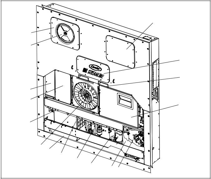
2.1.1 Refrigeration Unit -- Front Section
The unit is designed so that the majority of the components are accessible from the front, see Figure 2-1. The upper access panels allow entry into the evaporator section, and the center access panel allows access to the evaporator expansion valve, unloader
15
14
13
12
11
10
9
8
7
6
valve, suction modulation valve and evaporator coil heaters. The unit model number, serial number and parts identification number can be found on the serial plate to the left of the economizer.
2.1.2 Fresh Air Makeup Vent
The function of the upper or lower makeup air vent is to provide ventilation for commodities that require fresh air circulation.
1
2
3
4
16
5
1. |
Access Panel (Evap. Fan #1) |
|
Parts Identification Number (PID) Plate |
2. |
Access Panel (Heaters, Suction Modulating |
9. |
Power Cables and Plug |
|
Valve, Unloader Valve & Evaporator |
10. |
Condenser Fan |
|
Expansion Valve) |
11. |
Interrogator Connector (Front left) |
3. |
Fork Lift Pockets |
12. |
Blank Cover (Temperature Recorder Location) |
4. |
Control Box |
13. |
Blank Cover (Lower Fresh Air Makeup Vent |
5. |
Compressor |
|
Location) |
6. |
Receiver or Water Cooled Condenser |
14. |
Upper Fresh Air Makeup Vent |
7. |
Economizer |
15. |
Access Panel (Evap. Fan #2) |
8. |
Unit Serial Number, Model Number and |
16. |
Compressor Protection Panel (cutaway view) |
|
Figure 2-1 Refrigeration Unit -- Front Section |
||
|
2-1 |
|
T-309 |

2.1.3 Evaporator Section
The evaporator section (Figure 2-2) contains the return recorder sensor, return temperature sensor, evaporator expansion valve, unloader valve, suction modulation valve, dual-speed evaporator fans (EM1 and EM2), evaporator coil and heater, defrost heaters, defrost temperature sensor, heat termination thermostat and suction temperature sensor.
The evaporator fans circulate air through the container by pulling it in the top of the unit, directing it through the evaporator coil, where it is heated or cooled, and discharging it at the bottom.
The evaporator components are accessible by removing the upper rear panel (as shown in the illustration) or by removing the front access panels.
3 |
|
5 |
|
|
|
|
|
|
|
7 |
|
|
|
|
|
|
|
4 |
|
|
|
|
|
2 |
|
|
|
|
|
1 |
|
|
|
|
|
8 |
|
|
|
|
|
|
|
|
11 |
12 |
6 |
|
10 |
17 |
|
||
9 |
|
|
|
||
|
|
|
|
||
15 |
|
|
|
|
|
14 |
|
|
|
|
|
16 |
|
|
|
|
|
|
|
13 |
|
|
|
1. |
Evaporator Fan Motor #1 |
10. |
Evaporator Expansion Valve |
2. |
Return Recorder/Temperature Sensor |
11. |
Low Side Access Valve |
3. |
Humidity Sensor |
12. |
Suction Modulating Valve |
4. |
Evaporator Fan Motor #2 |
13. |
Suction Temperature Sensor |
5. |
Defrost Temperature Sensor |
14. |
To Compressor |
6. |
Heater Termination Thermostat |
15. |
From Coil |
7. |
Evaporator Coil |
16. |
To Coil |
8. |
Evaporator Coil Heaters |
17. |
Unloader Solenoid Valve |
9.Evaporator Expansion Valve Bulb
Figure 2-2 Evaporator Section
T-309 |
2-2 |

2.1.4 Compressor Section
The compressor section includes the compressor (with high pressure switch) and the oil separator.
This section also contains the oil return solenoid, compressor power plug, the discharge pressure
transducer, discharge temperature sensor and the suction pressure transducers.
The supply temperature sensor, supply recorder sensor and ambient sensor are located at the left side of the compressor.
|
|
|
|
|
2 |
|
|
|
|
1 |
|
|
|
|
|
|
4 |
|
|
|
23 |
|
|
|
|
22 |
9 |
|
|
|
|
|
|
|
|
|
|
|
10 |
|
|
|
|
21 |
|
|
|
20 |
|
|
11 |
|
Discharge |
19 |
|
|
Connection |
||
18 |
|
|
|
(Hidden) |
|
17 |
|
|
|
|
Economizer |
|
|
|
12 |
8 |
|
|
|
|
Connection |
||
|
|
|
13 |
||
|
|
|
|
Suction |
|
|
|
|
|
|
|
|
|
|
11 |
7 |
Connection |
|
|
|
Oil Return |
||
|
|
|
14 |
|
Connection |
|
|
16 |
6 |
|
|
|
|
|
5 |
||
|
|
|
11 |
||
|
|
|
|
||
|
|
|
|
|
|
|
|
|
15 |
|
|
|
3 |
|
|
|
|
1. |
Compressor Guard |
12. |
Economizer Service Valve |
2. |
Supply Temperature/Supply Recorder Sensor |
13. |
Suction Service Valve |
|
Assembly |
14. |
Discharge Temperature Sensor |
3. |
Ambient Sensor |
15. |
Oil Return Service Valve |
4. |
Supply Air Thermometer Port (location) |
16. |
Discharge Pressure Transducer |
5. |
Oil Drain |
17. |
Oil Return Solenoid Valve |
6. |
Compressor |
18. |
Oil Separator |
7. |
Compressor Sight Glass |
19. |
From Economizer |
8 |
Compressor Power Plug |
20. |
To Condenser |
9. |
Discharge Service Valve |
21. |
From Suction Modulating Valve |
10. |
High Pressure Switch |
22. |
Suction Strainer |
11. |
Access Valve |
23. |
Suction Pressure Transducer |
Figure 2-3 Compressor Section
2-3 |
T-309 |
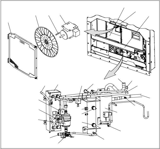
2.1.5 Air Cooled Condenser Section
The air cooled condenser section (Figure 2-4) consists of the condenser fan, condenser coil, receiver, sight glass/moisture indicator, liquid line service valve, filter-drier and fusible plug.
The condenser fan pulls air in the bottom of the coil and it is discharged horizontally out through the condenser fan grille.
This section also contains the economizer, economizer solenoid valve, economizer expansion valve and the liquid injection solenoid valve.
|
|
|
5 |
|
2 |
3 |
4 |
6 |
|
7 |
||||
|
||||
|
|
|
1
|
|
|
|
12 |
11 |
|
|
8 |
10 |
14 |
|
|
9 |
13 |
|||
|
|
|
|
|
|
|
27 |
|
|
|
15 |
|
|
|
|
|
|
|
26 |
|
22 |
|
16 |
|
|
17 |
|
||
|
|
|
21 |
|
|
|
|
|
|
|
|
|
25 |
|
20 |
|
|
|
|
|
|
|
|
|
|
|
|
18 |
|
|
24 |
|
|
19 |
|
|
|
23 |
|
|
|
|
|
|
|
|
|
1. |
Grille and Venturi Assembly |
|
15. |
From Compressor Discharge |
|
2. |
Condenser Fan |
|
16. |
Discharge Pressure Transducer |
|
3. |
Key |
|
17. |
Oil Separator |
|
4. |
Condenser Fan Motor |
|
18. |
To Oil Return Solenoid |
|
5. |
Condenser Coil |
|
19. |
Receiver |
|
6. |
Condenser Motor Mounting Bracket |
20. |
Sight Glass/Moisture Indicator |
||
7. |
Condenser Coil Cover |
|
21. |
Sight Glass |
|
8. |
Economizer |
|
22. |
Fusible Plug |
|
9. |
To Evaporator Expansion Valve |
|
23. |
Access Valve |
|
10. |
Liquid Injection Solenoid Valve |
|
24. |
Liquid Line Service Valve |
|
11. |
From Condenser |
|
25. |
Filter-Drier |
|
12. |
To Condenser |
|
26. |
Economizer Expansion Valve |
|
13. |
To Compressor Economizer Connection |
27. |
Economizer Solenoid Valve |
|
|
14.To Unloader Solenoid Valve
Figure 2-4 Condenser Section
T-309 |
2-4 |

2.1.6 Control Box Section |
|
|
|
|
|
2.1.7 Communications Interface Module |
|
|
||||||||||||||||||||||||||
The control box (Figure 2-5) includes the manual |
The communications interface module is a slave |
|||||||||||||||||||||||||||||||||
operation switches; circuit breaker (CB-1); compressor, |
module which allow communication with a master |
|||||||||||||||||||||||||||||||||
fan and heater contactors; control power transformer; |
central monitoring station. The module will respond to |
|||||||||||||||||||||||||||||||||
fuses; key pad; display module; current sensor module; |
communication and return information over the main |
|||||||||||||||||||||||||||||||||
controller module expansion module and the |
power line. Refer to the master system technical manual |
|||||||||||||||||||||||||||||||||
communications interface module. |
|
|
|
|
|
for further information. |
|
|
|
|
|
|
|
|
|
|
|
|
|
|
|
|
||||||||||||
1 |
2 |
|
|
|
|
|
|
3 |
|
|
|
|
4 |
5 |
|
6 |
7 |
8 |
||||||||||||||||
|
|
|
|
|
|
|
|
|
|
|
|
|
|
|
|
|
|
|
|
|
|
|
|
|
|
|
|
|
|
|
|
|
|
|
|
|
|
|
|
|
|
|
|
|
|
|
|
|
|
|
|
|
|
|
|
|
|
|
|
|
|
|
|
|
|
|
|
|
|
|
|
|
|
|
|
|
|
|
|
|
|
|
|
|
|
|
|
|
|
|
|
|
|
|
|
|
|
|
|
|
|
|
|
|
|
|
|
|
|
|
|
|
|
|
|
|
|
|
|
|
|
|
|
|
|
|
|
|
|
|
|
|
|
|
|
|
|
|
|
|
|
|
|
|
|
|
|
|
|
|
|
|
|
|
|
|
|
|
|
|
|
|
|
|
|
|
|
|
|
|
|
|
|
|
|
|
|
|
|
|
|
|
|
|
|
|
|
|
|
|
|
|
|
|
|
|
|
|
|
|
|
|
|
|
|
|
|
|
|
|
|
|
|
|
|
|
|
|
|
|
|
|
|
|
|
|
|
|
|
|
|
|
|
|
|
|
|
|
|
|
|
|
|
|
|
|
|
|
|
|
|
|
|
|
|
|
|
|
|
|
|
|
|
|
|
|
|
|
|
|
|
|
|
|
|
|
|
|
|
|
|
|
|
|
|
|
|
|
|
|
|
|
|
|
|
|
|
|
|
|
|
|
|
|
|
|
|
|
|
|
|
|
|
|
|
|
|
|
|
|
|
|
|
|
|
|
|
|
|
|
|
|
|
|
|
|
|
|
|
|
|
|
|
|
|
|
|
|
|
|
|
|
|
|
|
|
|
|
|
|
|
|
|
|
|
|
|
|
|
|
|
|
|
|
|
|
|
|
|
|
|
|
|
|
|
|
|
|
|
|
|
|
|
|
|
|
|
|
|
|
|
|
|
|
|
|
|
|
|
|
|
|
|
|
|
|
|
|
|
|
|
|
|
|
|
|
|
|
|
|
|
|
|
|
|
|
|
|
|
|
|
|
|
|
|
|
|
|
|
|
|
|
|
|
|
|
|
|
|
|
|
|
|
|
|
|
|
|
|
|
|
|
|
|
|
|
|
|
|
|
|
|
|
|
|
|
|
|
|
|
|
|
|
|
|
|
|
|
|
|
|
|
|
|
|
|
|
|
|
|
|
|
|
|
|
|
|
|
|
|
|
|
|
|
|
20 |
19 |
18 |
17 |
16 |
15 |
14 |
13 |
12 |
11 |
10 |
9 |
1. |
Compressor Phase A Contactor |
|
|
11. |
Manual Defrost Switch |
|
|
|
|
|||
2. |
Compressor Phase B Contactor |
|
|
12. |
Condenser Fan Switch |
|
|
|
|
|||
3. |
Heater Contactor |
|
|
|
|
13. |
Controller Battery Pack |
|
|
|
|
|
4. |
Display Module |
|
|
|
|
14. |
Interrogator Connector (Box Location) |
|
|
|||
5. |
Communications Interface Module |
|
|
15. |
Control Transformer |
|
|
|
|
|||
6. |
Controller/DataCORDER Module (Controller) |
|
16. |
Evaporator Fan Contactor - High |
|
|
|
|||||
7. |
Expansion Module |
|
|
|
|
17. |
Evaporator Fan Contactor - Low |
|
|
|
||
8. |
Key Pad |
|
|
|
|
|
18. |
Condenser Fan Contactor |
|
|
|
|
9. |
Start-Stop Switch |
|
|
|
|
19. |
Circuit Breaker -- 460V |
|
|
|
|
|
10. |
Remote Monitoring Receptacle |
|
|
20. |
Current Sensor Module |
|
|
|
|
|||
Figure 2-5 Control Box Section
2-5 |
T-309 |

2.2 REFRIGERATION SYSTEM DATA
|
|
Model |
RSH105 |
|
|
|
|
|
|
|
|
Weight (Dry) |
46.5 kg (103 lb) |
|
a. Compressor/Motor |
Approved Oil |
Mobil ST32 |
||
|
|
|||
Oil Charge |
2957 ml (100 ounces) |
|||
|
Assembly |
|||
|
|
|
The oil level range, with the compressor off, |
|
|
|
Oil Sight Glass |
should be between the bottom and one-eighth |
|
|
|
|
level of the sight glass. |
|
b. Evaporator Expansion |
Verify at -18 _C |
|
||
(0 _F) container box |
4.4 to 6.7 _C (8 to 12 _F) |
|||
|
Valve Superheat |
|||
|
temperature |
|
||
|
|
|
||
|
|
|
||
c. Economizer Expansion |
|
4.4 to 11.1 _C (8 to 20 _F) |
||
|
Valve Superheat |
|
||
|
|
|
||
d. Heater Termination Thermostat |
Opens |
54 (¦ 3) _C = 130 (¦ 5) _F |
||
|
|
|||
Closes |
38 (¦ 4) _C = 100 (¦ 7) _F |
|||
e. High Pressure Switch |
Cutout |
25 (¦ 1.0) kg/cm@ = 350 (¦ 10) psig |
||
|
|
|||
Cut-In |
18 (¦ 0.7) kg/cm@ = 250 (¦ 10) psig |
|||
|
|
|||
|
|
|
|
|
|
|
Unit Configuration |
Charge Requirements - R-134a |
|
|
|
|||
|
|
|
4-Row Coil |
|
|
|
Water-Cooled |
||
|
|
|
||
f. |
Refrigerant Charge |
5.33 kg |
||
Condenser |
||||
(11.75 lbs) |
||||
|
|
|
||
|
|
Receiver |
4.99kg |
|
|
|
(11.0 lbs) |
||
|
|
|
||
g. Fusible Plug |
Melting point |
99 _C = (210 _F) |
||
|
|
|||
Torque |
6.2 to 6.9 mkg (45 to 50 ft-lbs) |
|||
|
|
|||
|
|
|
||
h. Sight Glass/Moisture Indicator |
Torque |
8.9 to 9.7 mkg (65 to 70 ft-lbs) |
||
|
|
|
|
|
i. |
Rupture Disc |
Bursts at |
35 ¦ 5% kg/cm@ = (500 ¦ 5% psig) |
|
|
|
|||
Torque |
6.2 to 6.9 mkg (45 to 50 ft-lbs) |
|||
|
|
|||
|
|
|
|
|
j. |
Unit Weight |
Refer to unit model number plate. |
||
|
|
|
|
|
k. Water Pressure Switch |
Cut-In |
0.5 ¦ 0.2 kg/cm@ (7 ¦ 3 psig) |
||
|
|
|||
Cutout |
1.6 ¦ 0.4 kg/cm@ (22 ¦ 5 psig) |
|||
|
|
|||
|
|
|
|
|
T-309 |
2-6 |
2.3 |
ELECTRICAL DATA |
|
|
|
|
|
|
CB-1 Trips at |
29 amps |
||
|
|
|
|
||
a. Circuit Breaker |
CB-2 (50 amp) Trips at |
62.5 amps |
|||
|
|
CB-2 (70 amp) Trips at |
87.5 amps |
||
|
|
|
|
|
|
b. Compressor |
Full Load Amps (FLA) |
13 amps @ 460 vac |
|||
|
Motor |
||||
|
|
|
|
|
|
|
|
|
380 vac, Single Phase, |
|
460 vac, Single Phase, |
|
|
|
50 hz |
|
60 hz |
c. |
Condenser Fan |
Full Load Amps |
1.3 amps |
|
1.6 amps |
|
Motor |
Horsepower |
0.43 hp |
|
0.75 hp |
|
|
|
|
|
|
|
|
Rotations Per Minute |
1425 rpm |
|
1725 rpm |
|
|
|
|
|
|
|
|
Voltage and Frequency |
360 -- 460 vac ¦ 2.5 hz |
|
400 -- 500 vac ¦ 2.5 hz |
|
|
|
|
|
|
|
|
Bearing Lubrication |
Factory lubricated, additional grease not required. |
||
|
|
|
|
||
|
|
Rotation |
Counter-clockwise when viewed from shaft end. |
||
|
|
|
|
|
|
|
|
Number of Heaters |
|
4 |
|
|
|
|
|||
d. Evaporator Coil |
Rating |
750 watts +5/--10% each @ 230 vac |
|||
|
Heaters |
Resistance (cold) |
66.8 to 77.2 ohms @ 20 _C (68 _F) |
||
|
|
|
|
||
|
|
Type |
Sheath |
||
|
|
|
|
|
|
|
|
|
380 vac/50 hz |
|
460 vac/60 hz |
|
|
|
|
|
|
|
|
Full Load Amps |
1.6 |
|
2.0 |
|
|
High Speed |
|
||
|
|
|
|
|
|
|
|
Full Load Amps |
0.8 |
|
1.0 |
|
|
Low Speed |
|
||
|
|
|
|
|
|
|
|
Nominal Horsepower |
0.70 |
|
0.84 |
|
|
High Speed |
|
||
|
|
|
|
|
|
|
|
Nominal Horsepower |
0.09 |
|
0.11 |
e. |
Evaporator Fan |
Low Speed |
|
||
|
|
|
|||
|
Motor(s) |
Rotations Per Minute |
2850 rpm |
|
3450 rpm |
|
|
High Speed |
|
||
|
|
|
|
|
|
|
|
Rotations Per Minute |
1425 rpm |
|
1750 rpm |
|
|
Low Speed |
|
||
|
|
|
|
|
|
|
|
Voltage and Frequency |
360 -- 460 vac ± 1.25 hz |
|
400 -- 500 vac ± 1.5 hz |
|
|
|
|
|
|
|
|
Voltage & Frequency us- |
180 -- 230 vac ± 1.25hz |
|
200 -- 250 vac ± 1.5 hz |
|
|
ing power autotransformer |
|
||
|
|
|
|
|
|
|
|
Bearing Lubrication |
Factory lubricated, additional grease not required |
||
|
|
|
|
||
|
|
Rotation |
CW when viewed from shaft end |
||
|
|
|
|
||
|
|
Control Circuit |
10 amps (F3) |
||
|
|
|
|
||
f. |
Fuses |
Controller/DataCORDER |
5 amps (F1 & F2) |
||
|
|
Expansion Module |
10 amps (F4) |
||
2-7 |
T-309 |
PARAGRAPH 2.3 -- Continued
|
Orange wire |
Power |
|
|
|
|
|
|
Red wire |
Output |
|
|
|
|
|
|
Brown wire |
Ground |
|
|
|
|
|
|
Input voltage |
5 vdc |
|
|
|
|
|
g. Humidity Sensor |
Output voltage |
0 to 3.3 vdc |
|
Output voltage readings verses relative humidity (RH) percentage: |
|||
|
|||
|
|
|
|
|
30% |
0.99 V |
|
|
|
|
|
|
50% |
1.65 V |
|
|
|
|
|
|
70% |
2.31 V |
|
|
|
|
|
|
90% |
2.97 V |
|
|
|
|
|
2.4 SAFETY AND PROTECTIVE DEVICES
Unit components are protected from damage by safety and protective devices listed in the following table. These devices monitor the unit operating conditions and open a set of electrical contacts when an unsafe condition occurs.
Open safety switch contacts on either or both of devices
IP-CP or HPS will shut down the compressor.
Open safety switch contacts on device IP-CM will shut down the condenser fan motor.
The entire refrigeration unit will shut down if one of the following safety devices open: (a) Circuit Breaker(s);
(b) Fuse (F3/15A); or (c) Evaporator Fan Motor Internal Protector(s) - (IP-EM).
Table 2-1 Safety and Protective Devices
UNSAFE CONDITION |
DEVICE |
DEVICE SETTING |
|
|
|
|
|
|
Circuit Breaker (CB-1) - Manual Reset |
Trips at 29 amps (460 vac) |
|
|
|
|
|
Excessive current draw |
Circuit Breaker (CB-2, 50 amp) -Manual Reset |
Trips at 62.5 amps (230 vac) |
|
|
Circuit Breaker (CB-2, 70 amp) -Manual Reset |
Trips at 87.5 amps (230 vac) |
|
|
|
|
|
Excessive current draw in the |
Fuse (F3) |
10 amp rating |
|
control circuit |
|||
|
|
||
Excessive current draw by the |
Fuse (F1 & F2) |
5 amp rating |
|
controller |
|
|
|
Excessive current draw by the |
Fuse (F4) |
10 amp rating |
|
expansion module |
|
|
|
Excessive condenser fan mo- |
Internal Protector (IP-CM) - Automatic Reset |
N/A |
|
tor winding temperature |
|||
|
|
||
Excessive compressor motor |
Internal Protector (IP-CP) - Automatic Reset |
N/A |
|
winding temperature |
|||
|
|
||
Excessive evaporator fan mo- |
Internal Protector(s) (IP-EM) - Automatic Reset |
N/A |
|
tor(s) winding temperature |
|||
|
|
||
Abnormal pressures/tempera- |
Fusible Plug - Used on the Receiver |
93 _C = (200 _F) |
|
|
|
||
tures in the high refrigerant |
Rupture Disc - Used on the Water-Cooled Con- |
35 kg/cm@ = (500 psig) |
|
side |
|||
denser |
|
||
|
|
||
|
|
|
|
Abnormally high discharge |
High Pressure Switch (HPS) |
Opens at 25 kg/cm@ |
|
pressure |
(350 psig) |
||
|
|||
|
|
|
T-309 |
2-8 |
2.5 REFRIGERATION CIRCUIT 2.5.1 Standard Operation
Starting at the compressor, (see Figure 2-6, upper schematic) the suction gas is compressed to a higher pressure and temperature.
In the standard mode, both the economizer and unloader solenoid valves are closed. The gas flows through the discharge service valve into the oil separator. In the separator, oil is removed from the refrigerant and stored for return to the compressor when the oil return solenoid valve is opened by the controller. The oil return solenoid valve is a normally open valve which allows return of oil during the off cycle.
The refrigerant gas continues into the air-cooled condenser. When operating with the air-cooled condenser active, air flowing across the coil fins and tubes cools the gas to saturation temperature. By removing latent heat, the gas condenses to a high pressure/high temperature liquid and flows to the receiver which stores the additional charge necessary for low temperature operation.
When operating with the water cooled condenser active (see Figure 2-6, lower schematic), the refrigerant gas passes through the air cooled condenser and enters the water cooled condenser shell. The water flowing inside the tubing cools the gas to saturation temperature in the same manner as the air passing over the air cooled condenser. The refrigerant condenses on the outside of the tubes and exits as a high temperature liquid. The water cooled condenser also acts as a receiver, storing excess refrigerant.
The liquid refrigerant continues through the liquid line service valve, the filter-drier (which keeps refrigerant clean and dry) and the economizer (which is not active during standard operation) to the evaporator expansion valve. As the liquid refrigerant passes through the variable orifice of the expansion valve, some of it vaporizes into a gas (flash gas). Heat is absorbed from the return air by the balance of the liquid, causing it to vaporize in the evaporator coil. The vapor then flows through the suction modulation valve to the compressor.
The evaporator expansion valve is activated by the bulb strapped to the suction line near the evaporator outlet. The valve maintains a constant superheat at the coil outlet regardless of load conditions.
On systems fitted with a water pressure switch, the condenser fan will be off when there is sufficient pressure to open the switch. If water pressure drops below the switch cut out setting, the condenser fan will be automatically started. When operating a system fitted with a condenser fan switch, the condenser fan will be off when the switch is placed in the “O” position. The condenser fan will be on when the switch is placed in the “I” position.
2.5.2 Economized Operation
In the economized mode the frozen range and pull down capacity of the unit is increased by subcooling the liquid refrigerant entering the evaporator expansion valve. Overall efficiency is increased because the gas leaving the economizer enters the compressor at a higher pressure, therefore requiring less energy to compress it to the required condensing conditions.
During economized operation, flow of refrigerant through the main refrigerant system is identical to the standard mode. (The unloader solenoid valve is de-energized [closed] by the controller.)
Liquid refrigerant for use in the economizer circuit is taken from the main liquid line as it leaves the filter-drier (see Figure 2-7). The flow is activated when the controller energizes the economizer solenoid valve. The liquid refrigerant flows through the economizer expansion valve and the economizer internal passages absorbing heat from the liquid refrigerant flowing to the evaporator expansion valve. The resultant “medium” temperature/pressure gas enters the compressor at the economizer service valve.
2.5.3 Unloaded Operation
The system will operate in the unloaded mode during periods of low load, during periods of required discharge pressure or current limiting, and during start-up.
During unloaded operation, flow of refrigerant through the main refrigerant system is identical to the standard mode. (The economizer solenoid valve is de-energized [closed] by the controller.)
In the unloaded mode, a portion of the mid-stage compressed gas is bypassed to decrease compressor capacity. The flow is activated when the controller opens the unloader solenoid valve (see Figure 2-7. Opening of the valve creates a bypass from the economizer service valve through the unloader solenoid valve and into the suction line on the outlet side of the suction pressure modulation valve.
As load on the system decreases, the suction modulating valve decreases flow of refrigerant to the compressor. This action balances the compressor capacity with the load and prevents operation with low coil temperatures. In this mode of operation, the liquid injection solenoid valve will open as required to provide sufficient liquid refrigerant flow into the suction line for cooling of the compressor motor.
2-9 |
T-309 |

STANDARD OPERATION WITH RECEIVER
|
EVAPORATOR |
LOW SIDE ACCESS VALVE |
|
|
|
|
|
||
|
TXV BULB |
|
SMV |
|
|
TXV |
|
|
|
|
CONDENSER |
|
|
|
|
|
|
USV |
|
|
LIV |
|
|
|
|
|
|
|
STS |
FILTER |
ECONOMIZER TXV BULB |
|
|
|
|
|
|
|
|
DRIER |
|
|
|
DISCHARGE |
|
ECONOMIZER |
|
|
|
|
|
DPT |
SERVICE |
|
|
|
|
||
|
|
|
CONNECTION |
|
|
|
|
|
|
|
ESV |
|
CPDS |
HPS |
|
|
|
||
|
OIL SEPARATOR |
|
ECONOMIZER |
|
|
|
|
|
SERVICE |
ECONOMIZER |
RECEIVER |
|
|
CONNECTION |
|
ORV |
|
||
TXV |
|
|
|
|
|
|
|
|
|
|
FUSIBLE PLUG |
|
|
SUCTION SERVICE |
|
SIGHT GLASS |
|
|
CONNECTION |
|
MOISTURE INDICATOR |
|
OIL RETURN |
SPT |
|
|
|
SERVICE VALVE |
|
LIQUID LINE |
|
|
|
|
|
|
|
|
|
SERVICE |
|
|
|
|
CONNECTION |
|
|
COMPRESSOR |
|
|
|
|
|
|
|
DISCHARGE |
LIQUID |
SUCTION |
|
STANDARD OPERATION WITH WATER COOLED CONDENSER
|
EVAPORATOR |
|
LOW SIDE ACCESS VALVE |
|
|
|
|
|
|
|
|
|
|
TXV BULB |
SMV |
|
|
|
|
TXV |
|
|
|
|
CONDENSER |
|
|
|
|
|
|
|
USV |
|
|
|
|
LIV |
|
|
|
|
|
|
|
QUENCH |
CPSS |
|
|
|
|
TXV |
|
|
|
|
|
BULB |
|
FILTER |
ECONOMIZER TXV BULB |
|
|
|
|
|
|
|
|
|
|
DRIER |
|
|
|
DISCHARGE |
|
|
ECONOMIZER |
|
|
|
|
|
|
|
SERVICE |
|
|
|
|
|
DPT |
|
|
|
|
|
CONNECTION |
|
|
|
|
|
|
|
|
|
ESV |
RUPTURE DISC |
CPDS |
HPS |
|
|
|
|
|||
|
|
|
|
ECONOMIZER |
|
|
|
|
|
SERVICE |
|
|
ECONOMIZER |
|
|
CONNECTION |
|
|
|
ORV |
|
|
|
|
TXV |
|
|
|
|
|
|
|
|
|
|
|
SIGHTGLASS/ |
|
|
SUCTION SERVICE |
|
|
MOISTURE INDICATOR |
|
|
|
|
|
|
|
|
CONNECTION |
|
|
|
|
OIL RETURN |
SPT |
|
|
|
WATER COOLED |
SERVICE VALVE |
|
|
|
LIQUID LINE |
|
|
||
|
|
|
|
||
|
SERVICE |
CONDENSER |
|
|
|
|
CONNECTION |
|
COMPRESSOR |
|
|
|
|
|
|
|
|
Figure 2-6 Refrigeration Circuit Schematic -- Standard Operation
T-309 |
2-10 |

EVAPORATOR |
LOW SIDE ACCESS VALVE |
|
|
TXV BULB |
SMV |
TXV |
|
CONDENSER |
|
|
LIV |
|
ECONOMIZER TXV BULB |
|
|
ECONOMIZER |
|
|
ESV |
|
|
|
OIL SEPARATOR |
|
|
ECONOMIZER |
|
ECONOMIZER |
SERVICE |
|
CONNECTION |
||
TXV |
||
|
||
RECEIVER |
|
|
LIQUID LINE |
|
|
SERVICE CONNECTION |
|
|
LIQUID |
ECONOMIZER PRESSURE |
Figure 2-7 Refrigeration Circuit Schematic -- Economized Operation
|
TXV BULB |
SMV |
|
TXV |
|
|
|
USV |
|
LIV |
|
ECONOMIZER TXV BULB |
|
|
|
OIL SEPARATOR |
|
|
|
SUCTION SERVICE |
|
|
CONNECTION |
RECEIVER |
|
|
LIQUID |
ECONOMIZER PRESSURE |
SUCTION |
Figure 2-8 Refrigeration Circuit Schematic -- Unloaded Operation
2-11 |
T-309 |

SECTION 3
MICROPROCESSOR
3.1TEMPERATURE CONTROL MICROPROCESSOR SYSTEM
The temperature control Micro-Link 2i microprocessor system (see Figure 3- 1) consists of a key pad, display module, the control module & expansion module set (controller) and interconnecting wiring. The controller houses the temperature control software and the DataCORDER Software. The temperature control software functions to operate the unit components as required to provide the desired cargo temperature and humidity. The DataCORDER software functions to
record unit operating parameters and cargo temperature parameters for future retrieval. Coverage of the temperature control software begins with paragraph 3.2. Coverage of the DataCORDER software is provided in paragraph 3.6.
The key pad and display module serve to provide user access and readouts for both of the controller functions, temperature control and DataCORDER. The functions are accessed by key pad selections and viewed on the display module. The components are designed to permit ease of installation and removal.
C |
CONTROL MODULE |
DISPLAY MODULE |
O |
|
|
N |
|
|
T |
|
|
R |
|
|
O |
|
|
L |
EXPANSION MODULE |
|
L |
|
|
E |
|
|
R |
|
KEY PAD |
|
|
TEMPERATURE CONTROL SOFTWARE |
|
||||
CONFIGURATION |
OPERATIONAL |
ALARMS |
PRE--TRIP |
INTERROGATION |
|
SOFTWARE |
SOFTWARE |
(AL<70) |
|
CONNECTOR |
|
CONFIGURATION |
FUNCTION |
TO |
|
|
|
VARIABLE |
CODE (Cd) |
DISPLAY |
|
|
|
(CnF##) |
|
|
|
||
|
|
|
|
||
|
DataCORDER SOFTWARE |
|
DATAREADER |
||
|
|
|
|||
CONFIGURATION |
OPERATIONAL |
ALARMS |
DATA |
|
|
SOFTWARE |
SOFTWARE |
(AL>69) |
STORAGE |
|
|
|
|
|
MEMORY |
|
|
CONFIGURATION |
FUNCTION |
TO |
TO |
Computer Device |
|
VARIABLE |
CODE (dC) |
DISPLAY |
With DataLine |
||
DISPLAY |
|||||
(dCF## read only) |
|
Software |
|||
|
|
(Scrollback) |
|||
|
|
|
|
||
Figure 3- 1 Temperature Control System
3-1 |
T-309 |
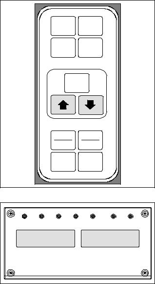
3.1.1 Key Pad
The key pad (Figure 3- 2) is mounted on the right-hand side of the control box. The key pad consists of eleven push button switches that act as the user’s interface with the controller. Descriptions of the switch functions are provided in Table 3-1.
CODE |
PRE |
SELECT |
TRIP |
ALARM |
DEFROST |
LIST |
INTERVAL |
|
|
ENTER |
|
RETURN |
_C |
SUPPLY |
_F |
BATTERY |
ALT. |
POWER |
MODE |
Figure 3- 2 Key Pad
COOL |
HEAT DEFROST IN RANGE ALARM |
SUPPLY RETURN |
|
|
SETPOINT/Code |
AIR TEMPERATURE/Data |
|
Figure 3- 3 Display Module 3.1.2 Display Module
The display module (Figure 3- 3) consists of two backlighted five digit LCD displays and seven indicator lights. The indicator lights include:
1.Cool - White LED: Energized when the refrigerant compressor is energized.
2.Heat - Orange LED: Energized to indicate heater operation in the heat or defrost mode.
3.Defrost - Orange LED: Energized when the unit is in the defrost mode.
4.In-Range - Green LED: Energized when the controlled temperature probe is within specified tolerance of set point.
|
Table 3-1 Key Pad Function |
|
|
|
|
KEY |
|
FUNCTION |
Code Select |
|
Accesses function codes. |
|
|
|
Pre-Trip |
|
Displays the pre-trip selection menu. Dis- |
|
continues pre-trip in progress. |
|
|
|
|
Alarm List |
|
Displays alarm list and clears the alarm |
|
|
queue. |
Defrost |
|
Displays selected defrost interval. |
Interval |
|
|
|
|
|
Enter |
|
Confirms a selection or saves a selection |
|
to the controller. |
|
|
|
|
Arrow Up |
|
Change or scroll a selection upward Pre- |
|
trip advance or test interruption. |
|
|
|
|
Arrow |
|
Change or scroll a selection downward. |
Down |
|
Pre-trip repeat backward. |
Return/ |
|
Displays non-controlling probe tempera- |
Supply |
|
ture (momentary display). |
|
|
Displays alternate English/Metric scale |
|
|
(momentary display). When set to _F, |
|
|
pressure is displayed in psig and vacuum |
|
|
in “/hg. “P” appears after the value to in- |
_C/_F |
|
dicate psig and “i” appears for inches of |
|
|
mercury. |
|
|
When set to _C. pressure readings are in |
|
|
bars. “b” appears after the value to indi- |
|
|
cate bars. |
|
|
|
Battery |
|
Initiate battery backup mode to allow set |
|
point and function code selection if AC |
|
Power |
|
|
|
power is not connected. |
|
|
|
|
|
|
|
|
|
This key is pressed to switch the functions |
|
|
from the temperature software to the Da- |
ALT Mode |
|
taCORDER Software. The remaining keys |
|
function the same as described above ex- |
|
|
|
cept the readings or changes are made to |
|
|
the DataCORDER programming.. |
|
|
NOTE |
The controlling probe in the perishable range will be the SUPPLY air probe and the controlling probe in the frozen range will be the RETURN air probe.
5.Supply - Yellow LED: Energized when the supply air probe is used for control. When this LED is illuminated, the temperature displayed in the AIR TEMPERATURE display is the reading at the supply air probe. This LED will flash if dehumidification or humidification is enabled.
6.Return - Yellow LED: Energized when the return air probe is used for control. When this LED is illuminated, the temperature displayed in the AIR TEMPERATURE display is the reading at the return air probe. This LED will flash if dehumidification or humidification is enabled.
7.Alarm - Red LED: Energized when there is an active or an inactive shutdown alarm in the alarm queue
T-309 |
3-2 |

1 |
|
2 |
3 |
3 |
4 |
5 |
3 |
6 |
7 |
3 |
8 |
3 |
|
|
|
|
|
|
|
|
|
|
|
||
1 |
9 |
|
3 |
3 |
3 |
|
3 |
|
3 |
|
|
|
|
|
|
|
|
|
|
|
|
|
|
1. |
Mounting Screw |
6. |
Control Circuit Power Connection |
2. |
Micro-Link 2i Control/DataCORDER Module |
|
(Location: In back of controller) |
3. |
Connectors |
7. |
Software Programming Port |
4. |
Test Points |
8. |
Battery Pack |
5. |
Fuses |
9. |
Expansion Module |
Figure 3- 4 Control and Expansion Modules
3.1.3 Controller
CAUTION
Do not remove wire harnesses from control-
ler modules unless you are grounded to the unit frame with a static safe wrist strap.
CAUTION
Unplug all controller module wire harness connectors before performing arc welding
on any part of the container.
NOTE
Do not attempt to service the controller modules. Breaking the seal will void the warranty.
The Micro-Link 2i controller is a dual module microprocessor as shown in Figure 3- 4. It is fitted with test points, harness connectors and a software card programming port.
3.2 CONTROLLER SOFTWARE
The controller software is a custom designed program that is subdivided into the Configuration Software and the Operational Software. The controller software performs the following functions:
a.Control supply or return air temperature to required limits, provide modulated refrigeration operation, economized operation, unloaded operation, electric heat control and defrost. Defrost is performed to clear build up of frost and ice and ensure proper air flow across the coil.
b.Provide default independent readouts of set point and supply or return air temperatures.
c.Provide ability to read and (if applicable) modify the Configuration Software Variables, Operating Software Function Codes and Alarm Code Indications.
d.Provide a Pre-Trip step-by-step checkout of refrigeration unit performance including: proper component operation, electronic and refrigeration control operation, heater operation, probe calibration, pressure limiting and current limiting settings.
e.Provide battery powered ability to access or change selected codes and set point without AC power connected
f.Provide the ability to reprogram the software through the use of a memory card. The memory card automatically downloads new software to the controller when inserted.
3.2.1Configuration Software (Configuration Variables)
The Configuration Software is a variable listing of the components available for use by the Operational Software. This software is factory installed in accordance with the equipment fitted and options listed on the original purchase order. Changes to the Configuration Software are required only when a new controller hase been installed or a physical change has been made to the unit such as the addition or removal of an option. A Configuration Variable list is provided in Table 3-4. Change to the factory installed Configuration Software is achieved via a configuration card or communications.
3-3 |
T-309 |
 Loading...